

Page 1
Operator’ s Manual
30-Foot, Folding, Soybean Machine
Model Serial No.
2SBD30 A1029+
Manufacturing, Inc.
www .g reatplainsmfg.com
Read the operator’s manual entirely. When you see this symbol, the subsequent in-
!
structions and warnings are serious -follow without exception. Your life and thelivesof
others depend on it!
2SBD30
© Copyright 1999 Printed 5/3/2005
12632
Cover illustration may show optional equipment not supplied with standard unit.
173-086M
Page 2

General Information
General Information
Important Notice
Great Plains Manufacturing, Inc. provides this publication “as is” without warranty of any kind, either
expressed or implied, while every precaution has been
taken in the preparation of this manual, Great Plains
Manufacturing,Inc. assumes no responsibility for errors
oromissions.Neither is any liability assumed for damages resulting from the use of the information contained
herein. Great Plains Manufacturing, Inc. reserves the
righttoreviseand improveitsproductsasitseesfit.This
This Operators Manual applies to the 30’ 2-Section
Folding Soybean Machine:
Owner’s Information
publicationdescribesthe state of this product atthetime
of its publication, and may not reflect the product at all
times in the future.
Printed in the United States of America.
For your convenience, record your Serial Number,Mod-
el Number and the Date Purchased in the spaces
provided below. Have this information before you when
calling a Great Plains Authorized Dealer.
Name: _____________________________________
Address ____________________________________
City________________State ____ Zip
Phone_______________________
Name of Dealership ___________________________
Dealer’s Name _______________________________
Address ____________________________________
City________________State ____ Zip
Phone_______________________
Serial Number ________________
Model Number________________
Date Purchased_______________
2SBD30 30-Foot, Folding, Soybean Machine 173-086M 5/3/05Great Plains Mfg., Inc.
Page 3

Table of Contents
Table of Contents
General Information. . . . . . . . . . . . . . . . . . . . . . . . . 0
Owner’s Information. . . . . . . . . . . . . . . . . . . . . . . 0
Table of Contents. . . . . . . . . . . . . . . . . . . . . . . . . . . 1
Using this Manual . . . . . . . . . . . . . . . . . . . . . . . . . . 2
Introduction . . . . . . . . . . . . . . . . . . . . . . . . . . . . . . . 2
General Operation & Repair . . . . . . . . . . . . . . . . 3
Transporting. . . . . . . . . . . . . . . . . . . . . . . . . . . . . 3
Tire Handling & Repair . . . . . . . . . . . . . . . . . . . . 3
Safety Decals. . . . . . . . . . . . . . . . . . . . . . . . . . . . 3
Section 1 Safety Rules. . . . . . . . . . . . . . . . . . . . . . . 3
Section 2 Assembly Instructions & Set-Up . . . . . . 7
Tire Inflation Chart. . . . . . . . . . . . . . . . . . . . . . . . 7
Torque Values Chart for UNC Threads . . . . . . . . 7
Assembly Instructions . . . . . . . . . . . . . . . . . . . . . 8
Tractor Hook-up. . . . . . . . . . . . . . . . . . . . . . . . . . 9
Tractor Hydraulic Hook-up. . . . . . . . . . . . . . . . . 10
Section 3 Hydraulics . . . . . . . . . . . . . . . . . . . . . . . 11
Bleeding The Lift Hydraulics . . . . . . . . . . . . . . . 11
Bleeding The Folding Hydraulics. . . . . . . . . . . . 11
Operating The Hydraulic System. . . . . . . . . . . . 12
Lifting. . . . . . . . . . . . . . . . . . . . . . . . . . . . . . 12
Unfolding. . . . . . . . . . . . . . . . . . . . . . . . . . . 12
Folding . . . . . . . . . . . . . . . . . . . . . . . . . . . . 13
Pull Bar Adjustment. . . . . . . . . . . . . . . . . . . . . . 14
Transporting. . . . . . . . . . . . . . . . . . . . . . . . . . . . 14
Section 4 Seeding Adjustments . . . . . . . . . . . . . . 15
Seed Rates . . . . . . . . . . . . . . . . . . . . . . . . . . . . 15
Seed Rate Chart (Pounds per acre) . . . . . . . . . 15
Section 5 Basic Operation . . . . . . . . . . . . . . . . . . 17
Drill Preparation And Field Operations . . . . . . . 17
Transporting. . . . . . . . . . . . . . . . . . . . . . . . . . . . 17
Preparing the Drill . . . . . . . . . . . . . . . . . . . . . . . 17
Leveling . . . . . . . . . . . . . . . . . . . . . . . . . . . . . . . 17
Opener Parallel Arms Adjustments . . . . . . . 17
Section 6 Drill & Gauge Wheel Adjustments . . . . 19
Transport Wheel Adjustments . . . . . . . . . . . . . . 19
Gauge Wheel Adjustments. . . . . . . . . . . . . . . . . 19
Down Force Row . . . . . . . . . . . . . . . . . . . . . . . . 19
Standard Spring Package . . . . . . . . . . . . . . 19
Row Unit Mounted Coulter. . . . . . . . . . . . . . . . . 20
Down Force Pressure Chart. . . . . . . . . . . . . . . . 20
Depth Adjustment. . . . . . . . . . . . . . . . . . . . . . . . 20
1 x 12 Closing Wheel Adjustments. . . . . . . . . . . 20
Closing Wheel Down Force Adjustment . . . 20
Closing Wheel Alignment. . . . . . . . . . . . . . . 21
Closing Wheel Offset. . . . . . . . . . . . . . . . . . 21
Closing Disk Adjustments. . . . . . . . . . . . . . . . . . 21
Seed Lok . . . . . . . . . . . . . . . . . . . . . . . . . . . . . . 22
Section 7 Maintenance & Lubrication. . . . . . . . . . 23
Maintenance. . . . . . . . . . . . . . . . . . . . . . . . . . . . 23
Storage. . . . . . . . . . . . . . . . . . . . . . . . . . . . . . . . 23
Upper Post Pivot. . . . . . . . . . . . . . . . . . . . . . . . . 23
Lubrication . . . . . . . . . . . . . . . . . . . . . . . . . . . . . 23
Lower Post Pivot. . . . . . . . . . . . . . . . . . . . . . . . . 23
Axle Bearings. . . . . . . . . . . . . . . . . . . . . . . . . . . 24
Box Pivot . . . . . . . . . . . . . . . . . . . . . . . . . . . . . . 24
Feeder Cup Drive Shaft Sprocket Bearing . . . . . 24
Parallel Arm . . . . . . . . . . . . . . . . . . . . . . . . . . . . 24
Chains . . . . . . . . . . . . . . . . . . . . . . . . . . . . . . . . 25
Flange Bearing. . . . . . . . . . . . . . . . . . . . . . . . . . 25
Section 8 Troubleshooting. . . . . . . . . . . . . . . . . . . 26
Section 9 Specifications . . . . . . . . . . . . . . . . . . . . 28
5/3/05 Great Plains Mfg., Inc.
2SBD30 30-Foot, Folding, Soybean Machine 173-086M
-1
Page 4
Using this Manual
Using this Manual
For your safety and to help in developinga better understanding of your equipment we highly recommend that
you read the operator sections of this manual. Reading
these sections not only provides valuable training but
also familiarizes you with helpful information and its lo-
Introduction
This manual has been prepared to instruct you in the
safeand efficient operationofyour30’ 2-Section Folding
Soybean Machine. Read and follow all instructions and
safety precautions carefully.
Read and follow all instructions and safety precautions
carefully.
The parts on your 30’ 2-Section Folding Soybean Machine have been specially designed and should only be
replaced with genuine Great Plains parts. Therefore,
should your 30’ 2-Section Folding Soybean Machine require replacement parts go to your Great Plains Dealer.
The right hand and left hand as used throughout this
manual is determined by facing in the direction the machine will travel when in use unless otherwise stated.
Serial Number
The serial number plate is located on the front of the left
hand transport axle post. It is suggested that the serial
number and purchase date also be recorded for your
convenience in the space provided.
Theserial number provides importantinformation about
your 30’ 2-Section Folding Bean Machine and may be
required to obtain the correct replacement part. Always
use the serial numberand model number when sending
correspondenceorwhenordering parts from your Great
Plains Dealer.
cation. The parts sections are for reference only and
don’trequire covertocoverreading.Afterreviewingyour
manual store it in a dry,easily accessible location for future reference.
safety precautions must be taken. When you see this
symbol, be alertand carefully read themessage that follows it. In addition to design and configuration of
equipment; hazard control and accident prevention are
dependentupon the awareness,concern,prudence and
proper training of personnel involved in the operation,
transport, maintenance and storage of equipment.
Watchforthe followingsafety notations through-out
your Operators Manual:
!
DANGER!
Indicates an imminently hazardous situation which, if
not avoided, will result in death or serious injury. This
signal word is limited to the most extreme situations.
!
WARNING!
Indicates a potentially hazardoussituation which, if not
avoided, could result in death or serious injury.
!
Indicates a potentially hazardoussituation which, if not
avoided, may result in minor or moderate injury.It may
also be used to alert against unsafe practices.
CAUTION!
!
The SAFETY ALERT SYMBOL indicates that there is a
potential hazard to personal safety involved and extra
2
2SBD30 30-Foot, Folding, Soybean Machine 173-086M 5/3/05
NOTE: Indicates a special point of information which
requires your attention.
Great Plains Mfg., Inc.
Page 5

Section 1 Safety Rules
Section 1 Safety Rules
Most accidents are the result of negligence and carelessness, usually caused by failure of the operator to
follow simple but necessary safety precautions. The followingsafetyprecautions are suggested to help prevent
such accidents. The safeoperation of any machinery is
a big concern to consumers and manufactures.Your 30’
2-SectionFoldingSoybeanMachinehasbeen designed
with many built-in safety features. However, no one
should operate this product beforecarefully reading this
Operators Manual.
!
General Operation & Repair
1. Never allow the 30’ 2-Section Folding Bean Machine to
be operated by anyone who is unfamiliar with the operation of all functions of the unit. All operators should read
and thoroughly understand the instructions given in this
manual prior to moving the unit.
2. Make sure safety rules are understood before operating
machinery or tractor.
3. Never permit any persons other than the operator to ride
on the tractor.
4. Never permit any persons to ride on or stand near the
drill while it is in operation.
5. Regulate your speed to the field conditions, maintaining
complete control at all times.
6. After repairing or adjusting, make sure all tools and
parts are removed from the implement before attempting
to operate it.
7. Do not grease or oil machine while it is in operation.
8. Loose fitting clothing should not be worn as it may catch
in moving parts.
9. Never dismount from a moving tractor.
10. Do not leave the tractor or the implement unattended
with the engine running.
11. Do not stand between the tractor and the implement during hitching.
12. Detach and store implements in an area where children
normally do not play. Stabilize implements by using suitable supports and block wheels.
13. If a hydraulic leak develops, correct it immediately. Escaping hydraulicoil can have extremely high pressure. A
stream of high pressure oil may easily penetrate the skin
as with modern needle-less vaccination equipment - but
with the exception that hydraulic fluid may cause blood
poisoning. It is imperative that the connections are tight
and that all lines and pipes are in good condition. If an
injury is caused by the escaping hydraulic fluid, see doctor at once!
14. Use a piece of cardboard or wood to detect leaks of hydraulic oil under pressure.
15. Be sure to relieve all hydraulic pressure before disconnection anylines or pipes between the implement and the tractor hydraulic system. Keep all guards and shields inplace.
Transporting
1. Use good judgement when transporting tractor and implements on the highway. Always maintain complete control of the machine.
2. Limit transport speed to 20 mph. Transport only with a
farm tractor of sufficient size and horse power.
3. Always make sure flashing safety lights, “Slow Moving
Vehicle” emblem, and reflectors are in place and visible
prior to transporting the machine on public roads.
4. Know your state and local laws concerning highway
safety and regulations. Comply with these laws when
transporting machinery.
5. Use warning flags or approved warning lights at night
and during other periods of poor visibility. Do your best
to prevent highway accidents.
6. Always make sure transport pins are in place to lock up
the drill in case a hydraulic hose ruptures during transport.
Tire Handling & Repair
1. Tire changing can be dangerous and should be preformed by trained personnel using the correct tools and
equipment.
2. Do not re-inflate a tire that has been run flat or seriously
under inflated. Have it checked by qualified personnel.
3. When removing and installing wheels, use wheel handling equipment adequate for the weight involved.
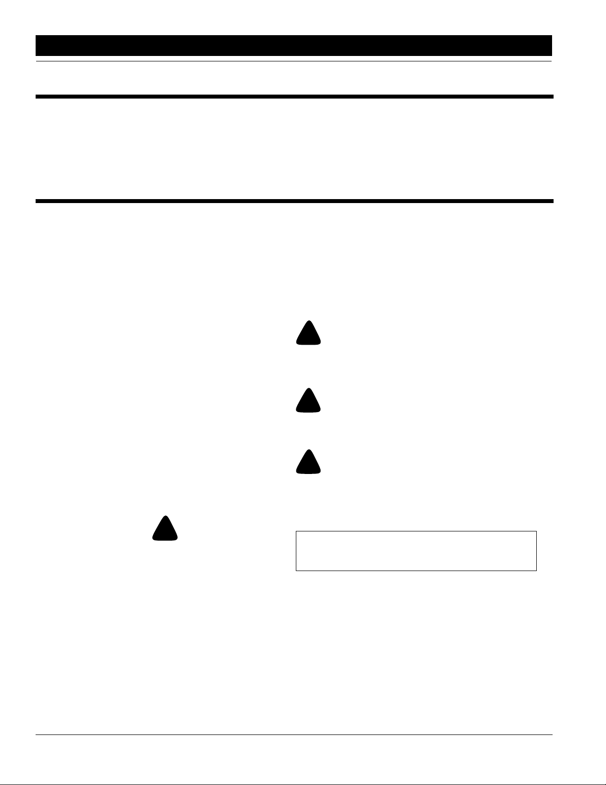
Safety Decals
1. Your 30’ 2-Section Folding Soybean Machine comes
equipped with all safety decals in place. They were designed to help you safely operate your 30’ 2-Section Folding Bean Machine. Read and follow their directions.
2. Keep safety decals clean and legible.
3. Replace all damaged or missing safety decals. To order
newsafety decals goto your Great Plains Dealerand refer
to the parts section for safety decal package part number.
4. Replace these decals whenever they become worn or unreadable. To instal new safety decals:
a. Clean the area the decal is to be placed
b. Peel backing from the decal. Press firmly on to sur-
face being careful not to cause air bubbles under the
decal.
5/3/05 Great Plains Mfg., Inc.
2SBD30 30-Foot, Folding, Soybean Machine 173-086M
-3
Page 6
Section 1 Safety Rules
12629
818-078C
General Caution
818-229C
Amber Reflectors
12476
818-230C
Red Reflector
12478
4
2SBD30 30-Foot, Folding, Soybean Machine 173-086M 5/3/05
Great Plains Mfg., Inc.
Page 7
Section 1 Safety Rules
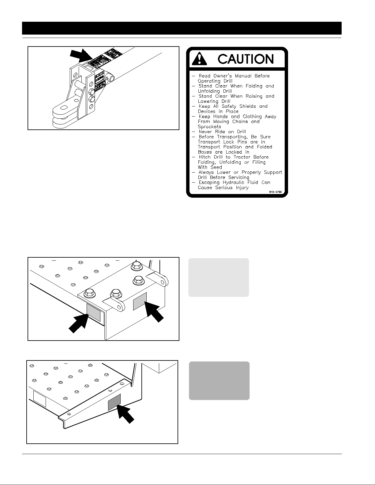
10222
818-003C
Slow Moving VehicleEmblem
12630
12631
818-020C
Caution Lowering Drill
818-188C
Transport Speed Warning
12475
5/3/05 Great Plains Mfg., Inc.
818-205C
Do Not Operate w/o Guard
in Place
2SBD30 30-Foot, Folding, Soybean Machine 173-086M
-5
Page 8
Section 1 Safety Rules
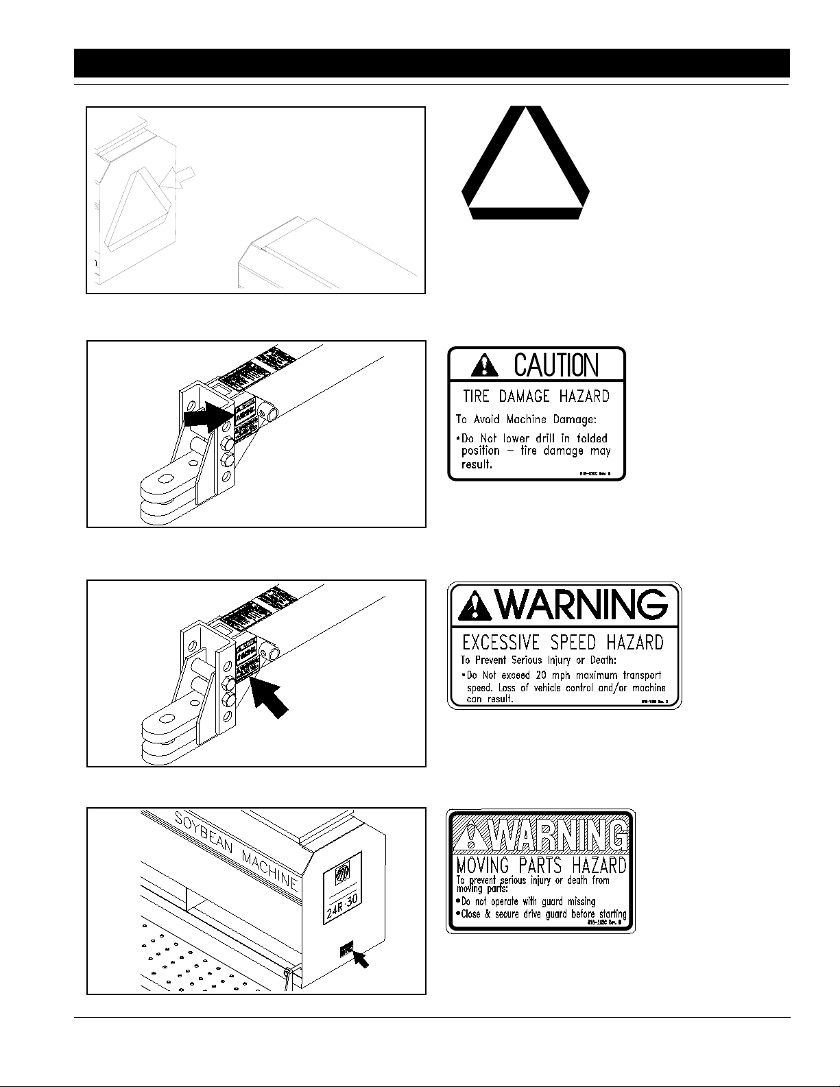
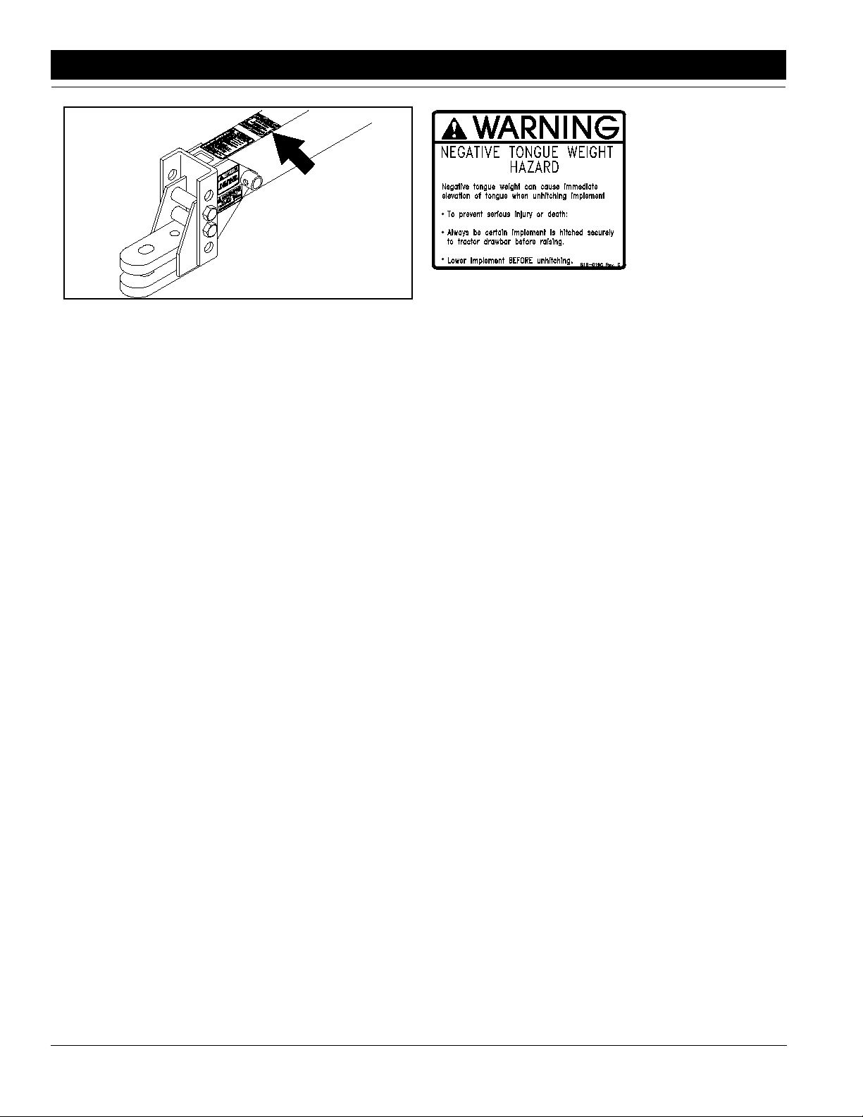
12628
818-019C
Warning Negative Tongue Weight
6
2SBD30 30-Foot, Folding, Soybean Machine 173-086M 5/3/05
Great Plains Mfg., Inc.
Page 9
Section 2 Assembly Instructions & Set-Up
Section 2 Assembly Instructions & Set-Up
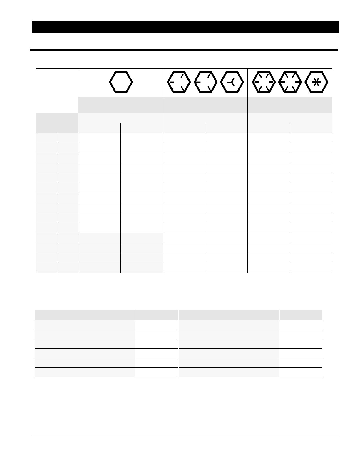
Torque Values Chart for UNC Threads
Bolt head
identification
marks are as per
grade.
NOTE: Manufacturing marks will vary.
Bolt Size
inches mm Min. Max. Min. Max. Min. Max. Min. Max. Min. Max. Min. Max.
1/4" 6.35
5/16" 7.94
3/8" 9.53
7/16" 11.11
1/2" 12.70
9/16" 14.29
5/8" 15.88
3/4" 19.05
7/8" 22.23
1" 25.40
1 1/8" 25.58
1 1/4" 31.75
1 3/8" 34.93
1 1/2" 38.10
Foot Pounds Newton-Meters Foot Pounds Newton-Meters Foot Pounds Newton-Meters
5 6 6.8 8.13 9 11 12.2 14.9 12 15 16.3 20.3
10 12 13.6 16.3 17 20.5 23.1 27.8 24 29 32.5 39.3
20 23 27.1 31.2 35 42 47.5 57.0 45 54 61.0 73.2
30 35 40.7 47.4 54 64 73.2 86.8 70 84 94.9 113.9
45 52 61.0 70.5 80 96 108.5 130.2 110 132 149.2 179.0
65 75 88.1 101.6 110 132 149.2 179.0 160 192 217.0 260.4
95 105 128.7 142.3 150 180 203.4 244.1 220 254 298.3 358.0
150 185 203.3 250.7 270 324 366.1 439.3 380 456 515.3 618.3
160 200 216.8 271.0 400 480 542.4 650.9 600 720 813.6 976.3
250 300 338.8 406.5 580 596 786.5 943.8 900 1080 1220.4 1464.5
Grade 2 Grade 5 Grade 8*
800 880 1084.8 1193.3 1280 1440 1735.7 1952.6
1120 1240 1518.7 1681.4 1820 2000 2467.9 2712.0
1460 1680 1979.8 2278.1 2380 2720 3227.3 3688.3
1940 2200 2630.6 2983.2 3160 3560 4285.0 4827.4
* Thick nuts must be used with Grade 8 bolts
NOTE: Torque requirements listed above do not apply to self-locking nuts. For self-locking nuts increase the torque requirements listed by 15%.
Tire Inflation Chart
Tire Size Inflation PSI
7.50 x 20" 4-Ply Drill Rib 28
9.0 x 22.5 10-Ply Highway Service 70 70
9.0 x 24" 8-Ply Rib Implement 40
9.5L x 15" 6-Ply Rib Implement 32
9.5L x 15" 8-Ply Rib Implement 44
9.5L x 15" 12-Ply Rib Implement 60
NOTE: All tires are warranted by the original manufacturer of the tire. Tire warranty information can be found in the
brochures included with your Operator’s and Parts Manuals or online at the manufacturer’s websites. For service assistance or information, contact your nearest Authorized Farm Tire Retailer.
Manufacturer Website
Titan www.titan-intl.com
Goodyear www.goodyearag.com
Firestone www.firestoneag.com
5/3/05 Great Plains Mfg., Inc.
Tire Size Inflation PSI
11L x 15" 6-Ply Rib Implement 28
11L x 15" 12-Ply Rib Implement 52
12.5L x 15" 8-Ply Rib Implement 36
12.5L x 15" 10-Ply Rib Implement 44
16.5L x 16.1" 10-Ply Rib Implement 36
41 x 15" x 18 - 22-Ply Rib Implement 44
2SBD30 30-Foot, Folding, Soybean Machine 173-086M
-7
Page 10
Section 2 Assembly Instructions & Set-Up
Assembly Instructions
1. Read “Section 1 Safety Rules” on page 3 before
assembling machine.
2. Setthe tongue approximately21"off the ground in a
horizontal position with stable blocking for support.
3. Raisethemain frame up,keepingthe side members
horizontal. Position the main frame over the tongue
and lower into position.
4. Secure tongue to main frame with 1"-6 x 2 1/2" long
bolts, lock washers and nuts.
5. Attach the tongue screw jack and remove blocking
so the unit is sitting on the ground.
6. Remove the safety wires from each hydraulic cylinder rod clevis between the tires and remove cylinders.See “Section 2BleedingLift Hydraulics” on
page 11.
7. Slide the hydraulic hoses from the mainframe
through the tongue and pull them out at the tractor
end. Attach tractor male couplers to the hydraulic
hoses.
8. Hook tractor up to the tongue and plug hydraulic
connectors into the tractor. With tractor running at
an idle speed, charge the machine hydraulic system. See “Section 2 Bleeding Lift Hydraulics” on
page 11. (Be sure your tractor has plenty of hydraulic fluid. This system requires approximately 3.3 gallons.)
9. Attach the gauge wheel turnbuckle to the gauge
wheel arm on each section and then mount the
wheel and tire.
10. Position the two drill boxes in line, end to end, with
the end chain drive sprockets outboard and approximately 3" between the machine boxes.
11. Using the tractor,back the machine’s main frame up
to the center of the two drill boxes. When getting
close, position the posts on each side of the main
framesothe faceofthe post mounting angles are towards the machine frames. Attach the post to the
machine frames using (16) 5/8"-11 x 1 3/4" long
bolts, (4) 5/8"-11 x 4" x 5 1/4" u-bolts, lock washers
and nuts. Tighten all the bolts and u-bolts.
12. Attach frame adjustment link from the machine
frame to the pivot post using the clevis pin with hair
pin cotters. Pin to pin centers should be adjusted to
approximately 38".
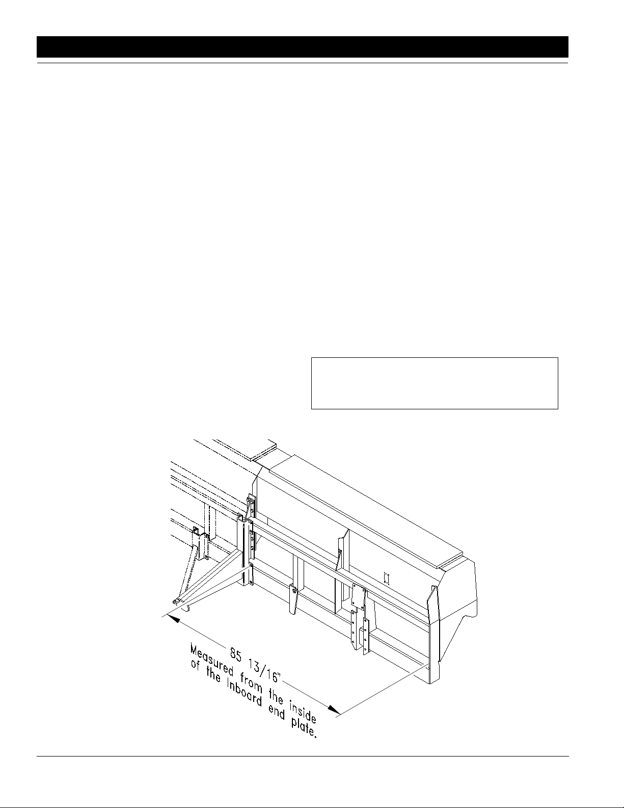
13. Locate the stabilizer frames inside mounting holes
85 13/16" from the inside of the inboard end of each
drill box frame,Figure 2-1. Using 5/8" u-bolts, 1/2" ubolts,5/8"-11 x 7" long bolts,lockwashersand nuts;
mount them to the box frame.
NOTE: One opener mounting u-bolt will be replaced
by 5/8"-11 x 7" long bolts.
10736
Stabilizer Frame
Figure 2-1
8
2SBD30 30-Foot, Folding, Soybean Machine 173-086M 5/3/05
Great Plains Mfg., Inc.
Page 11

Section 2 Assembly Instructions & Set-Up
14. Adjust clevis end of pull bars so that the distance
from the center of pull bar pin holes are approximately 134 1/4".
15. Mount pull bars to drill transport stabilizers and
tongue slide. With the tongue slide in the back position against its stop, adjust pull bar lengths so drills
are in line with one another and parallel to the back
edge of the main frame.
16. Raise the machine andplacethe transport lock pins
(2) in the transport position through the holes in the
main frame axle side tubes as shown in Figure 3-3.
17. Fold the machine, making sure that the tongue pull
bar slide moves smoothly up the tongue. When drill
boxesare almost foldedin, stop and adjust the postframe adjustment links on each box so that the tang
on each drill transport stabilizer frame lines up with
the nest on the front of the main frame. Fold machine completely closed. Refer to Figure 3-7 &
Figure 3-6.
18. With pull bar slide forward on the tongue and machine folded completely, position the pull bar lock
pin, across the top of the tongue slide as shown in
Figure 3-2. Adjust the transport lock bolt on top and
front of tongue up against lock pin with 1/16" clearance and lock the jam nut. This pin preventsthe machine from unfolding when in transport.
NOTE: Do not lower the Soybean Machine while it is
in the folding position.
11637
Clevis Hitch
Figure 2-3
Three sizes of hitches are available: The small hole clevis type hitch, Figure 2-3, (1 1/4" maximum pin diameter), the small hole strap hitch, and the large hole single
tang hitch, Figure 2-2, (up to 1 1/2" diameter pin). The
small hole clevis type hitch is sold as standard equipment. The mounting holes in the hitch have been offset
so the hitch can be turned over and bolted on in three
different positions giving you six different hitch heights
for both the single and clevis type
NOTE: Care should be taken when setting the hitch
so the tongue of the drill is parallel to the ground
when the drill is in the planting position.
Usetonguejacktolevel tongue, then find closest setting
of hitch to match your tractor drawbar height.
19. Checktoseethatall nuts andboltsaretight.See the
“Section 2 Torque Values Chart”, page 7, for
torque specifications.
Tractor Hook-up
The machine can be equipped with a single strap or clevis type hitch as shown in Figure 2-2 & Figure 2-3. Use
single strap when hooking up to a clevis type tractor
drawbar. Spacers between the drawbar and hitch may
be added to eliminate some of the movement of the
tongue caused from positive to negative tongue weight.
11638
Single Strap Hitch
Figure 2-2
Vertical Position
Figure 2-4
12624
5/3/05 Great Plains Mfg., Inc.
2SBD30 30-Foot, Folding, Soybean Machine 173-086M
-9
Page 12

Section 2 Assembly Instructions & Set-Up
The tongue jack makes it possible to raise or lower the
hitch for tractor unhooking and reconnecting. Always return jack to its horizontal storage position on top of the
tongue, Figure 2-5, and re-pinning before transporting
machine.
Storage Position
Figure 2-5
12625
!
This machine has both positive and negative tongue weight.
Never unhook from the tractor with the boxes unfolded and
raised off the ground.
CAUTION!
Tractor Hydraulic Hook-up
For easiest operation, your tractor should be equipped
withfourremote outlets (2 pair). One pair will be used for
lifting the machine. The second pair will be used for folding the machine.
!
Escaping fluidunder pressurecan have sufficient forceto penetrate the skin. Check all hydraulic lines and hoses before applying pressure. Fluid escaping from a very small hole can be
almost invisible. Use paper or cardboard, not body parts, to
check.
CAUTION!
10
2SBD30 30-Foot, Folding, Soybean Machine 173-086M 5/3/05
Great Plains Mfg., Inc.
Page 13

Section 3 Hydraulics
Section 3 Hydraulics
Bleeding The Lift Hydraulics
This folding machine is equipped with rephasing type
hydraulic lift cylinders that require a special procedure
for bleeding air from the hydraulic system. If your dealer
hasnotalreadypreparedthecylindersfortransportuse,
read the following information carefully. The rephasing
cylinders will not function properly if this bleeding procedure is not followed. Do not crack hose fittings in order
to bleed cylinders.
NOTE: Check the hydraulic fluid level in the tractor
reservoir and fill to the proper level before starting
this procedure. If the bleeding process is performed
with a low reservoirsupply,there is a chance of drawing air into the system. System capacity is approximately 3.3 gallons.
1. If required, raise your machine 1" in order to extend
yourlift cylinders a little. Loosen the jam nuts on top
of the transport vertical tubes and screw the adjustment screw in until it bottoms. Lower the machine a
small amount until the cylinders become loose.
2. Unpin the cylinders from the main frame and turn
the cylinders upside down to a position where the
rodend is higher than the base end. Supportthecylinders in a safe location. One transport tire may
haveto be removed in order to unpin the master cylinder.
3. Start the tractor and runthe engine at idle. With the
rod end of the cylinders higher than the base end,
hydraulically extend the cylinders and hold the tractorcontrol leverin position forsixtyseconds after the
cylinders haveextended to their maximum stroke.
4. Hydraulically retract the cylinders, then repeat the
extending procedure several more times until both
cylinders are free of air and operate together.
5. Repin the cylinders to the main frame, rod end
down. If air is trapped in either cylinder, the affected
cylinder will have a spongy, erratic movement and
the machine will not raise evenly. Refill the tractor
hydraulic fluid reservoir to its proper level.
NOTE: After machine is raised, a slight settling will
occur due to the action of the rephasing cylinders.
IMPORTANT: When using sealant on pipe threads, the
friction between the threads is reduced; therefore, be
certain not to over tighten causing damage to the cylinders, valves, or fittings.
Bleeding The Folding Hydraulics
NOTE: The Bean Machine liftsystem should be completely operational before attempting to set up the
folding hydraulic circuit.
1. Withthe machine unfolded & lowered to the ground.
Unpin the rod end of each fold cylinder and support
cylinders so it will not fall.
2. Make sure the tractor hydraulic fluid reservoir is
filled to the proper level.System capacity is approximately 1/2 gallon and requires 1 remote outlet.
3. Hook up the folding cylinder hydraulichoses to the
tractor remote outlets.
4. Loosenthe hose connection at thebaseendofeach
cylinder.
5. With the tractor at idle, slowly work the tractor remote lever to extend the cylinders.
6. When the cylinders are fully extended, tighten the
two base end connections.
7. Repeat the procedure with the hose connection at
the rod end ports.
8. Reconnect hydraulic cylinders.
NOTE: The JIC type hose connections do not require sealant or high torque fora good seal when reconnecting.
9. Refillthetractorhydraulic fluidreservoir to itsproper
level.
NOTE: The lift cylinders are rephasing type cylinders. This bleeding procedure will not work on
rephasing cylinders. See “Section 2 Bleeding Lift
Hydraulics” on page 11 for correct bleeding procedure.
5/3/05 Great Plains Mfg., Inc.
10. If the fold cylinders do not operate properly, clean
out small orifice hole in fittings circled on fold hydraulics illustration, Figure 3-1.
2SBD30 30-Foot, Folding, Soybean Machine 173-086M
-11
Page 14

Section 3 Hydraulics
Operating The Hydraulic System
Lifting
The lift cylinders may after a period of time get out of
time or phase. The effectsof this can be seen when one
cylinder is either overextended or over retracted comparedtothe other lift cylinders.Torephasethecylinders,
raise the machine completely up and hold the tractor hydraulic lever on for a few seconds to give the cylinders
time to rephase. This should be done each time the machine is raised out of the ground. Momentarily reversing
the hydrauliclever immediately after rephasing to allow
thecylinderstoretractabout1/2"willhelpinmaintaining
a level drill.
Unfolding
1. Removepin from pull-bar transportlock, Figure 3-2.
Pin must alwaysbe used when transporting the machine in the folded position.
2. Unfoldboxesusing hydrauliccylinders. Do this very
slowly and carefully. Serious damage could occur if
done fast and carelessly. Folding and unfolding is
best achieved on level ground. Install lock pin in bar
slide.
Fold Hydraulics
12
2SBD30 30-Foot, Folding, Soybean Machine 173-086M 5/3/05
Great Plains Mfg., Inc.
Page 15

Section 3 Hydraulics
Pull Bar Pin Transport Lock Location
Figure 3-2
10739
Pull Bar Pin In Field Location
Figure 3-5
10730
Transport Lock Pin Location
Figure 3-3
12608
3. Apply hydraulicpressureto the raising and lowering
system. Raising the machine may be required to
free up the transport lock pins in the vertical tubes
For removal, Figure 3-3.
4. Place pins into storage position, Figure 3-4
5/3/05 Great Plains Mfg., Inc.
Pins in Storage Location
Figure 3-4
10740
Folding
1. To fold the machine, reverse the order of the unfolding instructions. Be sure all transport devices are in
place before transporting, Figure 3-2 & Figure 3-3.
2SBD30 30-Foot, Folding, Soybean Machine 173-086M
-13
Page 16

Section 3 Hydraulics
2. When folding the machine, the machine transport
stabilizerframes should line up with the nests on the
front of the main frame, Figure 3-6.
Transport Stabilizer Frame
Figure 3-6
Iftheyscrapethe wing on the tongue, the boxes can
be raised or lowered by adjusting the wing adjustment clevis,Figure 3-7.
10673
10674
Wing Adjustment Clevis
Figure 3-7
Pull Bar Adjustment
With the machine completely unfolded, the drill boxes
should be in line with each other, and parallel to the
back of the main frame.
Should your drill boxes require alignment, simply disconnect the screw clevis end of the pull bar and screw it
in or out to move the box forward or backwards. Once
the boxes are aligned, be sure the pull bars are pinned
tothetongueslideand that the tongue slide is pinned for
field position.
Transporting
Before transporting the machine, you should always check the following items:
1. To preventpossibledamage in case of hydraulicfailure during transport, Always insert safety lock pins
when transporting, Figure 3-3.
2. Check to be sure the pull bar transport lock pin is in
position to insure boxes will not open during transport, Figure 3-2.
3. Checktoseeif you havethe requiredairpressure in
yourtires using the "Section 2 Tire Inflation Chart"
on page 7.
4. Whenin transport,useaccessorylightsanddevices
for adequate warning to other operators of other vehicles, and use safety hitch chain. Comply with all
14
2SBD30 30-Foot, Folding, Soybean Machine 173-086M 5/3/05
Great Plains Mfg., Inc.
Page 17

Section 4 Seeding Adjustments
Section 4 Seeding Adjustments
Seed Rates
NOTE: Seeding rates will vary greatly with variations
in sizes of the seeds. Although the seeding rates listedinthismanualarebasedonan averageseed size,
we recommend that you test and adjust your machine using the procedures listed below to help insure an accurate seeding rate.
1. Rotate each gauge wheel to see that feed cups and
drive are working properly and are free from foreign
matter.
2. To adjust your seeding rate, first you must decide
whichsprocketarrangement youneed(seeseeding
chart). In order to change sprockets, remove nut in
center of double speed change sprocket and turn it
over. Loosen the idler arm bolt, put chains on and
tighten both bolts. (The chains need to be reversed
to make this change.)
3. There are many factors which will affect seeding
rates: seed treatment, weight of seed, size of seed,
surface condition of seed, and tire configuration,
pressure and slippage. Minor adjustments will probablybe needed tocompensateforthe above factors.
4. The pounds-per-acre in the seed charts are based
onmachines having9.5L x 15" rib implement gauge
wheeltireswith proper air pressure."Section2Tire
Inflation Chart" on page 7.
5. The differences in seed size and treatment can
cause a wide variation in actual seeding rates. The
seed rate chart below is based on average size
seed. This may differ from the seed you are using.
Usetheseedratechartsas a guide. Set the poundsper-acredesired attheindicator numberforyourrow
spacing and complete the following procedure to
calibrate the machine for your specific seed.
a. Place several pounds of seed over three of the
feeder cups at the outboard end of one seed
box.
b. Pull the seed tubes out of these openers.
c. Raise the machine off the ground.
d. Place a container under the three seed tubes to
gather the seed as it is metered.
e. Rotatethe drive gauge wheel until one acre has
been tallied on the acremeter. This will be ap-
proximately 182 rotations on a 30’ machine. Be
sure to check the three feeder cups to make
sure each cup has plenty of seed coming into it.
f. Weigh the seed which has been metered. Di-
vide by three. This will give you the ounces/
poundsmeteredbyeach feeder cup.Multiply by
the number of openers on your machine to ar-
rive at the total pounds-per-acre you would
meter at that setting. If this figure is different
thandesired,set your feedcup adjustment lever
accordingly. Repeat procedures (a) through (f)
on both sections.
6. You may want to repeat the calibration procedure if
the results of your calibration vary greatly from the
suggested settings contained in this manual.
REMEMBER: Tire size and field conditions will also affect seeding rates. Be certain that your gauge wheel
tires are 9.5L x 15" and that they are inflated to the correct pressure. See "Section 2 Tire Inflation Chart" on
page 7. When planting check the amount of seed you
are using by noting acres planted, amount of seed added to machine and level of seed in box. If you suspect
that you are planting more or less seed than desired,
and you haveaccurately calibrated the machine to your
seed,youmayneed toadjustthe seeding rate slightly to
compensate for your field conditions.
Seed Rate Chart (Pounds per acre)
Setting number 5 10 15 20 25 30 35 40 45 50 55 60 65 70 75 80 85 90 95 100
Soybeans
Wheat 1 0 6 10 14 19 24 29 34 39 44 50 59 60 67 73 79 87 88 91 92
Cotton 1 2 4 6 10 12 16 18 22 26 28 34 38 40 42 50 58 64 68 70 72
Milo 2 1 4 6 9 12 14 18 22 23 27 32 33 36 39 41 44 52 53 54 55
Seed sizes vary.These Charts were calculated with average size cleaned seed. We strongly recommend that you test and adjust your
machine for accurate planting of your seed variety.
5/3/05 Great Plains Mfg., Inc.
1 0 0 8 10 17 25 30 34 40 49 54 60 68 73 78 82 93 94 95 96
Drive Type
2SBD30 30-Foot, Folding, Soybean Machine 173-086M
-15
Page 18

Section 4 Seeding Adjustments
10732
Drive Types
Figure 4-1
16
2SBD30 30-Foot, Folding, Soybean Machine 173-086M 5/3/05
Great Plains Mfg., Inc.
Page 19

Section 5 Basic Operation
Section 5 Basic Operation
Drill Preparation
And Field Operations
1. Your machine is equipped with an acremeter and it
should be mounted to the left gauge wheel axle. It
will accumulate the total acres planted. In order to
findouttheacrescovered, write downthebeginning
reading and subtract it from the ending reading for
the total acres planted.
2. Make sure that the feed cup adjustment handle on
each cup is set the same across the machine.
3. With the drill hookedup tothe tractor,load seed box
with seed. You should use cleaned seed to get the
best results.
4. Neverback up with row units in ground. If you do,
check all rows to be sure none are plugged.
5. Neverallow anyone to ride on the machine.
6. Maximum seeding speed should vary according to
soil conditions.
7. This Bean Machine is not designed to be turned
sharply in the field. Always lift the machine out of
the ground when turning at ends of field rows
and other short-radius turns. If the machineisnot
completelyraised,the lift hydraulicswillbecomeout
of sequence. See “Section 2 Bleeding Lift Hy-
draulics” on page 11.
8. Neverunhook the Bean Machine from tractor with
boxesunfolded and raised off the ground. Negative
tongue weight is present in this position.
If you notice excessive cracking on large seeds, adjust
all feeder cup door handles to a more open position.
10672
Threaded Stud
Figure 5-1
Make sure both studs have approximately the same
length of threads extending above the jam nut (approximately 3" for most planting conditions). Adjustments
mayberequiredandis coveredin “Section 6 Transport
Wheel Adjustments” on page 19. Put the transport
pins in storage position, Figure 3-4. Slowly lower the
machine until it is on the ground and the top slide cylinder is fully extended, Figure 5-2. Pull the machine
forward a few feet to make sure that the transport and
gauge wheel tires have firm contact with the soil.
Transporting
• This machine can be transported with a full box of
seed. It is best not to do this unless necessary because the increased weight does increase the chances for problems on the road. Do not exceed 20 miles
per hour.
• Be sure your gauge wheel tires have proper inflation
as listed in the "Section 2 Tire Inflation Chart" on
page 7.
• Comply with all Federal, State and Local Safety Laws
when traveling on public roads.
• Remember, the drill is wider than the tractor and ex-
treme care must be taken to allow for safe clearance.
Preparing the Drill
Unfold the machine on a levelseedbed typical to your
planting soil conditions.
At the top of both vertical axletubeson transport frameis
a threaded adjustment stud and jam nut, Figure 5-1.
5/3/05 Great Plains Mfg., Inc.
Top Slide Cylinder
Figure 5-2
10671
Leveling
Opener Parallel Arms Adjustments
The row unit parallel arms are the indicators of the level
of the machine, because they show the amount of down
float left in the row unit.
Lowerthe Bean Machine on alevelseedbed and pull for-
2SBD30 30-Foot, Folding, Soybean Machine 173-086M
-17
Page 20

Section 5 Basic Operation
ward a few feet then check the planters parallel arms.
The parallel arms should be levelwith the ground,
Figure 5-3.
If all the parallel arms along the Bean Machine are the
same,the machine is leveland youshould tighten down
thethreadedadjustment studs and jam nut as described
in“Section6 TransportWheel Adjustments” on page
19 for leveling. If the parallel arms vary, the Bean Ma-
chine can be leveled with transport and gauge wheel
adjustments described in "Section 6 Gauge Wheel Ad-
justments" on page 19.
!
If the planter vertical travel is decreased, considerable damage could occur to the planter units.
CAUTION!
12675
Level Parallel Arms
Figure 5-3
18
2SBD30 30-Foot, Folding, Soybean Machine 173-086M 5/3/05
Great Plains Mfg., Inc.
Page 21

Section 6 Drill & Gauge Wheel Adjustments
Section 6 Drill & Gauge Wheel Adjustments
Transport Wheel Adjustments
Whenlevelingyour Bean Machine, planter parallel arms
nearthe center of the machine that arehigherabovelevel than desired can be adjusted by raising the transport
frame. This is done by slowly raising the machine until
levelwith the hydrauliclift cylinders. Planter parallel
arms near the center that are lower than desired are adjusted by lowering the transport frame by retracting the
cylinders. Once the parallel arms are at the desired setting, screw the threaded adjustment studs on top of the
vertical tubes down as far as possible and secure them
with the jam nuts, Figure 5-1. This adjustment will stop
the lift cylinder travel at the same point each time the
boxesare lowered for planting and assures accurate
seed depth control.
NOTE: If it is noticedthat one box row’sparallel arms
are different from the other box at the center of your
machine is a sign that your lift hydraulic master and
slavecylinders are out of sequence with one another.
In order to get them back in sequence simply raise
your machine all the way up and hold your tractor hydraulic control valveleveron for a few seconds. Now
lower your machine and both cylinders will be in sequence with one another and your two boxes should
be at the same level again.
low easy gauge wheel adjustment. By lengthening the
turnbuckle the gauge wheel is lowered, also lowering
parallel arms.By shortening the turnbuckle the gauge
wheel is raised, also raising parallel arms.After adjusting, be sure the turnbuckle on both gauge wheel arms
have the same pin center dimensions.
Down Force Row
Standard Spring Package
The standard down force spring package, consists of 2
non-adjustable springs applying approximately
90 lbs. of down force.
Optional Medium and Heavy Duty Spring Package
The medium and heavy duty spring packages consist of
2or 4 adjustablesprings,respectively. The mediumduty
packagecanbe adjusted from approximately 100 to 200
lbs. down force. The heavy duty package can be adjusted from approximately 200 to 400 lbs. of down force.
Spring Adjustments
• All spring adjustments must be made with the ma-
chine in the fully raised position.
NOTE: The maximum down force stated before is
reached when the parallel arms are all the way up.
Gauge Wheel Adjustments
Theplanterrowsneartheoutsideof the machine are adjusted by raising or lowering the gauge wheels.
Raise the machine out of the ground and loosen the jam
nut located near the bottom clevis of the gauge wheel
turnbuckle,Figure 6-1. This turnbuckle is threaded to al-
10546
Gauge Wheel Turnbuckle
Figure 6-1
• The spring package is adjustable from 90 lbs. to 325
lbs. of down force when the parallel arms are horizontal. Consult the Down Force Pressure Chart on
page 20 to obtain the desired down force.
NOTE: The maximum down force stated before is
reached when the parallel arms are all the way up. To
adjust the spring tension, lift the plunger by pulling up
onthe roll pin handleandsliding the handle adjustment
assembly into the appropriate hole, see Figure 6-2.
• Two springs can be purchased at your Great Plains
Dealerto make the mediumdutypackageinto a heavy
duty package or two springs can be removed fromthe
heavydutypackage to make a medium duty package.
Add or subtract springs by removing the snap ring at
the end of the spring pivot rod. Slide the rod inward to
addorremoveaspringfromeachside.Thenattachor
remove the other spring end on the hex bar support.
Reinstall the spring rod and snap ring on each side.
5/3/05 Great Plains Mfg., Inc.
2SBD30 30-Foot, Folding, Soybean Machine 173-086M
-19
Page 22

Section 6 Drill & Gauge Wheel Adjustments
Down Force Pressure Chart
To Obtain This
* Down Force
90 lbs. 2 A
105 lbs. 2 B
125 lbs. 2 C
140 lbs. 2 D
160 lbs. 2 E
185 lbs. 4 A
215 lbs. 4 B
245 lbs. 4 C
285 lbs. 4 D
325 lbs. 4 E
* Force when arms are parallel.
Use This # of
Springs
In This
Hole
12208
Row Unit Mounted Coulter
Figure 6-3
Depth Adjustment
Theplantingdepth of the row unit is controlled by 2 walking gauge tires located next to the disks.
Adjust the planting depth as follows:
1. Raisethe machine to removeweightfromthe gauge
tires.
2. RaisetheT-handleand move it forward to decrease
the planting depth, see Figure 6-4. Moving the handle rearward increases the planting depth. Small increments of depth adjustment can be made by
walking the T-handle from side to side.
3. After one row is set to the desired depth, move the
T-handle on the other rows to the same location.
12137
Adjustment Bar
Figure 6-2
Row Unit Mounted Coulter
The optional coulter allows the planter to penetrate
tough ground conditions. It is recommended that either
the medium duty or heavy duty spring package be used
in conduction with this coulter.
Coulter Adjustments
1. To adjust the coulter vertically, loosen the 3/4" jam
nut and the 3/4" x 3" long hex bolt, see Figure 6-3.
2. Byturning the cam hex, rotatethecamcasting to set
the desired height. Forwavy coulter blades, it is recommended that the coulter blade should be run
even to 1" below the disks on the row unit.
3. Tighten the bolt and jam nut to torque values in
"Section 2 Torque Value Chart" on page
Reference3.
20
2SBD30 30-Foot, Folding, Soybean Machine 173-086M 5/3/05
12345
T-Handle Adjustment
Figure 6-4
1 x 12 Closing Wheel Adjustments
The 1 X 12 closing wheel option can be adjusted for
down force, alignment, and offset.
Closing Wheel Down Force Adjustment
Adjust the closing wheel down force to permit proper
closingof the seedtrench.It is recommendedtostart with
Great Plains Mfg., Inc.
Page 23

Section 6 Drill & Gauge Wheel Adjustments
the T-handle in the first of 4 notches, see Figure 6-5.
If the seed trench is not closing move the handle to the
next notch back and try again. Keep moving the handle
back until the seed trench is closing, by doing this eliminates unnecessary down force and compaction. In
some field conditions, the T-handle can be left in the forward slot to minimize down force.
Closing Wheel Adjuster
Figure 6-5
12346
Closing Wheel Alignment (Refer to Figure 6-6)
If one closing wheel is running in the seed trench or the
wheelsarenotcenteredoverthe seed trench, adjust the
closing wheels as follows:
1. Raise the machine slightly to remove weight from
the closing wheels.
2. Loosen the two 1/2" bolts.
3. Turn the press wheel adjuster left or right to center
the wheels over the seed trench.
4. Tighten the 1/2" bolts to the correct torque value listed in "Section 2 Torque Values Chart" on page
Reference3.
are not offset, the wheels should be located in the front
holes of the press wheel arm.
To offset the wheels, do as follows:
1. Raise machine slightly to remove weight on the
closing wheels.
2. Remove the 3/4” bolt holding the wheel,
see Figure 6-7.
3. Move the wheel to therearhole and attach with the 3/
4"bolt.Tighten the bolt to the correct torquevaluelisted in "Section 2 Torque Values Chart" on page
Reference3.
12347
Closing Wheel & Offset
Figure 6-7
Closing Disk Adjustments
The closing disk options consists of two disks and a
6 1/2 x 12 press wheel. The disk down pressure can be
adjusted to provide closing of the seed trench.
To adjust the down pressure, ratchet the spring cam to
the next cam height by turning the head of the support
bolt clockwise. Refer to Figure 6-8.
12418
Closing Wheel Alignment
Figure 6-6
Closing Wheel Offset
The 1x12 wheels can be offset to help prevent trash
from plugging the closing wheels. If the closing wheels
5/3/05 Great Plains Mfg., Inc.
12348
Closing disk & Tube Holes
Figure 6-8
2SBD30 30-Foot, Folding, Soybean Machine 173-086M
-21
Page 24

Section 6 Drill & Gauge Wheel Adjustments
Seed Lok
The seed lok option provides additional seed to soil contact. The seed lok is spring loaded and does not require
adjusting. In some wet and sticky conditions the wheel
may accumulate soil and may require removal of the
seed lok until conditions improve.
The seed lok is attached to the shank with a 1/2" clevis
pin,see Figure 6-9. To remove the seedlok,remove the
clevis pin and pull down on the seed lok mount. Reattach in the reverse order.
12362
Seed Lok Assembly
Figure 6-9
22
2SBD30 30-Foot, Folding, Soybean Machine 173-086M 5/3/05
Great Plains Mfg., Inc.
Page 25

Section 7 Maintenance & Lubrication
Section 7 Maintenance & Lubrication
Maintenance
Proper servicing and adjustment is the key to the long
life of any farm implement. With careful and systematic
inspection, you can avoid costly maintenance, time and
repair.
1. After using your implement forseveralhours, check
all bolts to be sure they are tight.
2. Lubricate the marker-body hinges every 15 hours of
operation.
3. Adjust idlers to remove excess slack from chains.
Clean and use chain lube on all roller chains as
needed.
4. Oil the seed-cup-drive sprocket in its square bore.
Move seed-cup adjustment leveraway from the
sprocketas faras possible togettheoilback into the
square.
5. Always maintain the proper air pressure in the rib
implement tires.
Lubrication
6. Replace any worn, damaged or illegible safety decalsbyobtainingnewdecals from your Great Plains
Dealer.
Storage
1. Clean the implement as necessary. Besure that the
seed boxes are completely cleaned before storing.
2. Lubricate and adjust all roller chains.
3. Lubricate all pivots as indicated in the followingillustrations.
4. Be sure to oil the seed-cup-drive sprocket before
storing the implement. Squirt oil on to the square
seed-cup shaft and move seed-cup-adjustment leverback and forth to gettheoilbackintothesquare.
5. Disconnect seed hoses from parallel-linkage openers. Permanent elongation and premature cracking
of hoses may occur if stored connected
6. Store the implement inside if possibleforlonger machine life.
Lubrication
Legend
12703
Multipurpose
spray lube
Multipurpose
grease lube
Multipurpose
oil lube
Upper Post Pivot
Type of Lubrication: Grease
Lower Post Pivot
Type of Lubrication:
50
20
20
Intervals at which
lubrication is required
5/3/05 Great Plains Mfg., Inc.
12704
2SBD30 30-Foot, Folding, Soybean Machine 173-086M
-23
Page 26

Section 7 Maintenance & Lubrication
20
Box Pivot
12705
16639
Type of Lubrication: Grease
5
Parallel Arm
Type of Lubrication: Grease
Seasonally
Axle Bearings
13520
Type of Lubrication: Grease
20
Feeder Cup Drive Shaft Sprocket Bearing
12126
24
2SBD30 30-Foot, Folding, Soybean Machine 173-086M 5/3/05
Type of Lubrication: Grease
Great Plains Mfg., Inc.
Page 27

Section 7 Maintenance & Lubrication
As
Required
Chain
13522
13522
Type of Lubrication: Spray
As
Required
Chain
Type of Lubrication: Spray
As
Required
Chain
13522
13519
5/3/05 Great Plains Mfg., Inc.
Type of Lubrication: Spray
20
Flange Bearing
Type of Lubrication: Grease
2SBD30 30-Foot, Folding, Soybean Machine 173-086M
-25
Page 28

Section 8 Troubleshooting
Section 8 Troubleshooting
Problem Solution
Uneven seed spacing or uneven stand a. Check for trash in seed cup.
b. Check to see if seed tubes are plugged.
c. Reduce ground speed.
d. Check planter disks to see they turn freely.
e. Use faster drive type speed and close feed cup flutes to a more
narrow position.
Planter disks not turning freely a. Check for trash or mud buildup on disk.
b. Check row frame for possible damage.
Actual seeding rate is different than
desired.
Excessive seed cracking
Acremeter doesn’t measure accurately a. Check tire pressure. Proper inflation is listed in “Section 2 Tire In-
Uneven seeding depth
Press Wheel not compacting the soil
as desired
Grain box not emptying evenly a. Certain models do not have the same number of seed cups be-
Feeder cup sprockets locked up or
twisted
a. Check tire pressure. Proper inflation is listed on page 6 in “Tire In-
flation Chart”.
b. Check tire size. Proper size is 9.5L x 15".
c. Liquid seed treatment will affect seeding rateif the chemicals build
upin feedcup.Unless cleanedregularly, this buildup cancause in-
creased torque and breakage of the feed shaft.
d. Check drive type. See "Section 4 Seed Rate Chart" page 15.
e. See instructions on calculating seed rate.
Change drive type to a slower speed and open flutes in feed cup to a wider position.
flation Chart” on page 7.
b. Check tire size. Proper size is 9.5L x 15".
c. Check planting operation for excessive overlap or gaps between
passes.
d. Loose soil conditions and slippage will cause variations in acres
registered.
e. To check accuracy of acremeter. See "Section 4 Seed Rates"
page 15.
Check to see that all planter units are adjusted the same.
Check the spring tension bolt on the back of the press wheel arm. The spring
pressure can be adjusted heavier or lighter.
tweeneach divider ofbulkhead.The sectionwiththelarger number
of cups will empty sooner.
b. If your machine has multiple boxes, check adjustment levers on
each box to see that they are set on the same indicator number.
a. Check for foreign matter lodged in one or more feeder drive shaft
feeder cups.
b. Liquidinsecticidefromseedhasdriedwithinthefeedcup.Remove
thebuild upbydisassembling eachfeedcup andscrapethe foreign
substance from the turning surfaces. NOTE: Liquid inoculant
should be applied with caution and care should be taken to clean
the feeder system after planting treated seeds.
26
2SBD30 30-Foot, Folding, Soybean Machine 173-086M 5/3/05
Great Plains Mfg., Inc.
Page 29

Section 8 Troubleshooting
Press Wheels and planters plugging a. Drilling in damp or wet conditions may increase this problem.
b. DONOTback up machine in field, or stop and allow machine to roll
backwards with openers in the ground.
Gauge Wheel leans to left or right a. Realign brackets where gauge wheel is attached to main frame by
adjusting the mounting bolts.
b. Checkto see if gauge wheel axle bearing are securely attached to
gauge wheel arm.
Improper folding of drills a. Adjust post frame adjusting links Figure 3-7 in
"Section 3" on page 14.
b. Check hydraulic system for air and oil leaks.
c. Clean out small orifice fittings in wing cylinders.
d. Make sure that the wing boxesunfold and are aligned, see “Sec-
tion 3 Pull Bar Adjustments”, on page 14.
Hydraulic adaptors cracking a. JIC fittings do not require high torque.
b. Always use liquid pipe sealant when adding or replacing pipe
thread hydraulic fittings. Plastic sealant can crack fittings and plug
hydraulic lines. JIC and O-ring fittings do not require sealant. Oring fittings require a thin coat of oil on the O-ring. IMPORTANT:
When using sealant on pipe threads the friction between the
threadsis reduced; therefore,be certainnottoovertightencausing
damage to the cylinders, valves, or fittings.
Raising and lowering machine is rough a. Lubricate lower rollers of verticaltransporttubes andunevenlocat-
ed between the transport tires.
b. Check hydraulic fittings for leaks.
c. Rephasing cylinders not properly bled. See “Section 3 Hydrau-
lics” on page 11. When raising machine at end of field the lifting
cylinders should be fully extended to insure that they are always
rephased.
5/3/05 Great Plains Mfg., Inc.
2SBD30 30-Foot, Folding, Soybean Machine 173-086M
-27
Page 30

Section 9 Specifications
Section 9 Specifications
Row Spacing
Numbers of Rows
Machine Weight
Box Length
Unfolded Machine Width
Tire Size
Box Capacity
Transpor t Width
Weights are based on machines equipped with planter units without coulter attachments.
15"
24
10,800 Pounds
15’
30’ - 6"
9.5L x 15" 6-Ply
2 Bushels/Foot
15’ - 6"
16’ - 10" with coulters
28
2SBD30 30-Foot, Folding, Soybean Machine 173-086M 5/3/05
Great Plains Mfg., Inc.
12604
Page 31

Section 9 Specifications
Great Plains Manufacturing, Incorporated warrants to the original purchaser that this seeding equipment will be free from defects in material
and workmanship for a period of one year from the date of original purchasewhen used as intended and undernormal service and conditions
for personal use; 90 days for commercial or rental purposes. This Warranty is limited to the replacement of any defective part by Great Plains
Manufacturing, Incorporated and the installation by the dealer of any
such replacement part. Great Plains reserves the right to inspect any
equipment or part which are claimed to have been defective in material
or workmanship.
This Warranty does not apply to any part or product which in Great
Plains’ judgement shall have been misused or damaged by accident or
lack of normal maintenance or care, or which has been repaired or altered in a way which adversely affects its performance or reliability, or
which has been used for a purpose for which the product is not designed. ThisWarranty shall not apply if the product is towed at a speed
in excess of 20 miles per hour.
Claims under this Warranty must bemade to the dealer whichoriginally
sold the product and all warranty adjustments must by made through
such dealer. Great Plains reserves the right to make changes in materials or design of the product at any time without notice.
This Warranty shall not be interpreted to render Great Plains liable for
damages of any kind, direct, consequential, or contingent, to property.
Furthermore,GreatPlainsshallnot be liable for damages resulting from
any cause beyond its reasonable control. This Warranty does not extend to loss of crops, losses caused by harvest delays or any expense
or loss for labor, supplies, rental machinery or for any other reason.
No other warranty of any kind whatsoever, express or implied, is
made with respect to this sale; and all implied warranties of merchantability and fitness for a particular purpose which exceed
the obligations set forth in this written warranty are hereby disclaimed and excluded from this sale.
This Warranty is not valid unless registered with Great Plains Manufacturing, Incorporated within 10 days from the date of original purchase.
Warranty
5/3/05 Great Plains Mfg., Inc.
2SBD30 30-Foot, Folding, Soybean Machine 173-086M
-29
Page 32

Great Plains Manufacturing, Inc.
Corporate Office: PO. Box 5060
Salina, Kansas 67402-5060 USA
 Loading...