

Page 1
Table of Contents Index
26-Foot Two-Section Folding HD Drill
Operator Manual
2S-2600HD
Manufacturing, Inc.
www.greatplainsmfg.com
Read the operator manual entirely. When you see this symbol, the
subsequent instructions and warnings are serious - follow without
exception. Your life and the lives of others depend on it!
17254
Illustrations may show optional equipment not supplied with standard unit or may
depict similar models where a topic is identical.
ORIGINAL INSTRUCTIONS
© Copyright 2014 Printed 2014-02-03 195-069M
Table of Contents Index
EN
Page 2

Table of Contents Index
Table of Contents Index
Page 3

Great Plains Manufacturing, Inc. Cover Index iii
Table of Contents
Important Safety Information ...................................... 1
Safety Decals ................................................................. 6
Introduction ................................................................11
Document Family .........................................................11
Description of Unit ........................................................11
Intended Usage ........................................................11
Models Covered .......................................................11
Using This Manual........................................................12
Definitions................................................................. 12
Owner Assistance ........................................................13
Preparation and Setup ...............................................14
Pre-Setup Checklist......................................................14
Hitching ........................................................................14
Electrical Connections..................................................16
Hydraulic Hose Hookup................................................17
Check Drill Level ..........................................................18
Setting the Bypass Valve .............................................19
Adjusting the Counter Balance Valve...........................20
Marker Setup................................................................21
Point Row Cab Module.................................................21
Shaft Monitor Cab Module............................................22
Scraper Installation.......................................................22
Operating Instructions...............................................23
General Description......................................................23
Pre-Start Checklist .......................................................24
Raising and Lowering Openers ....................................24
Opener Lock Up .......................................................24
Lock Up Openers..................................................24
Lowering Openers ................................................ 25
Raising Drill (Transport Lift)..........................................25
Transport Lift ............................................................25
Folding..........................................................................26
Transport ......................................................................28
Weights for Tractor Requirements............................28
Marker Transportation ..............................................28
Transport Checklist...................................................29
Unfolding ...................................................................... 30
Lowering Drill (Transport Lift) .......................................31
Transport Lower .......................................................31
Opener Operation.........................................................32
Active Hydraulic Systems.........................................33
Priority Flow Hydraulic Systems...............................34
Non-Active Hydraulic System...................................34
Loading Main Seed Box ............................................... 36
Main Seed Box Loading ........................................... 36
Small Seeds Box Loading ........................................ 36
Initial Seeding Depth ................................................ 37
Fertilizer Box Operation ............................................... 37
Seeding and applying fertilizer ................................. 37
Divided Capacities ............................................... 38
Divider Removal................................................... 38
Seeding with Both Compartments............................ 40
Marker Operation ......................................................... 41
Single Marker Operations ........................................ 41
Dual Marker Operations ........................................... 41
Lift Selector Valve Operation ....................................... 42
Point Row Operation.................................................... 42
Shaft Monitor Operation............................................... 43
Electronic Acremeter.................................................... 43
Parking......................................................................... 44
Parking with Drill Unfolded ....................................... 44
Parking with Drill Folded .......................................... 44
Storage ........................................................................ 45
Adjustments ............................................................... 46
Seed and Fertilizer Rate ...................................... 46
Planting Depth...................................................... 46
Setting Main Box Seed Rate........................................ 47
Setting Drive Type.................................................... 48
Changing Drive Type ........................................... 48
Main Box Seed Rate Handle....................................49
Position Seed Cup Doors.........................................49
Main Box Seed Rate Calibration .............................. 50
Reading a Seed Rate Chart ..................................... 52
Setting Fertilizer Rate .................................................. 53
Adjusting for Density ................................................ 53
Setting Fertilizer Drive Range .................................. 54
Setting High Range .............................................. 54
Setting Low Range............................................... 54
Setting Fertilizer Final Drive ..................................... 55
Fertilizer Rate Calibration......................................... 56
Small Seeds Rate ........................................................ 58
Small Seeds Rate Calibration .................................. 58
Frame Level ................................................................. 60
Frame Weight .............................................................. 61
Opener Frame Down-Force ......................................... 62
Setting Hydraulic Down-Pressure ............................ 63
Opener-Subframe Adjustment ..................................... 64
Row Unit Adjustments.................................................. 65
Opener Height..........................................................66
© Copyright 2007, 2009, 2010, 2012, 2013, 2014 All rights Reserved
Great Plains Manufacturing, Inc. provides this publication “as is” without warranty of any kind, either expressed or implied. While every precaution has been
taken in the preparation of this manual, Great Plains Manufacturing, Inc. assumes no responsibility for errors or omissions. Neither is any liability assumed for
damages resulting from the use of the information contained herein. Great Plains Manufacturing, Inc. reserves the right to revise and improve its products as
it sees fit. This publication describes the state of this product at the time of its publication, and may not reflect the product in the future.
2014-02-03 Cover Index 195-069M
Trademarks of Great Plains Manufacturing, Inc. include: Singulator Plus, Swath Command, Terra-Tine.
Registered Trademarks of Great Plains Manufacturing, Inc. include:
Air-Pro, Clear-Shot, Discovator, Great Plains, Land Pride, MeterCone, Nutri-Pro, Seed-Lok, Solid Stand,
Terra-Guard, Turbo-Chisel, Turbo-Chopper, Turbo Max, Turbo-Till, Ultra-Till, Ver ti-Till, Whirlfilter, Yield-Pro.
Brand and Product Names that appear and are owned by others are trademarks of their respective owners.
Printed in the United States of America
Page 4

iv 2S-2600HD Table of Contents Index Great Plains Manufacturing, Inc.
Row Unit Down Pressure (Spring) ........................... 66
Disk Blade Adjustments ........................................... 67
Adjusting Disc Contact ......................................... 67
Disk Scraper Adjustments........................................ 68
Seed Firmer Adjustments ........................................ 68
Keeton Seed Firmer Adjustment .......................... 68
Seed-Lok™ Seed Firmer Lock-Up ....................... 69
Opener Depth (Press Wheel Height) ....................... 69
Marker Adjustments ..................................................... 70
Marker Extension ..................................................... 70
Marker Chain Adjustment ........................................ 71
Marker Lifting Slack.............................................. 71
Marker Folding Slack ........................................... 71
Marker Disk Adjustment........................................... 72
Mark Width ........................................................... 72
Direction of Cut .................................................... 73
Marker Speed .......................................................... 73
Single Marker/Needle Valve Speed ..................... 74
Dual-Marker/Sequence Valve Speed................... 74
Troubleshooting......................................................... 75
Maintenance and Lubrication ................................... 78
Bleeding Hydraulics ..................................................... 79
Bleeding Opener Lift Hydraulics .............................. 80
Bleeding Fold Hydraulics ......................................... 81
Bleeding Transport Lift Hydraulics ........................... 82
Bleeding Marker Hydraulics ..................................... 83
In-Line Filters ............................................................... 83
Leveling the Drill .......................................................... 84
Opener Frames Level .............................................. 84
Link Tube ................................................................. 85
Tool Bar Height ........................................................ 85
Wing Box Alignment................................................. 86
Chain Maintenance.......................................................87
Chain Slack...............................................................87
Marker Maintenance.....................................................87
Marker Transport Carrier ..........................................87
Marker Shear Bolt.....................................................88
Marker Disk...............................................................88
Main Box Seed Meter Clean-Out..................................89
Fertilizer Box Clean-Out ...............................................89
Seed Flap Replacement (s/n DD1497+).......................90
Seed Flap Replacement (s/n DD1496-) .......................90
Lubrication ....................................................................91
Options ........................................................................99
Appendix A................................................................104
Specifications and Capacities.....................................104
Tire Inflation Chart ......................................................104
Torque Values Chart ..................................................105
Hydraulic Diagrams ....................................................106
Transport Lift...........................................................106
Fold.........................................................................106
Dual Markers ..........................................................107
Single Marker..........................................................107
Two Outlet Conversion ...........................................108
Opener Lift: Standard Closed-Center .....................109
Opener Lift: Optional Open-Center.........................110
Point-Row ...............................................................111
Appendix B - Previous Style Acremeter.................112
Acremeter Installation.................................................112
Acremeter Operation ..................................................112
Warranty .....................................................................114
Index ..........................................................................117
195-069M Table of Contents Index 2014-02-03
Page 5
Great Plains Manufacturing, Inc. Table of Contents Index 1
Important Safety Information
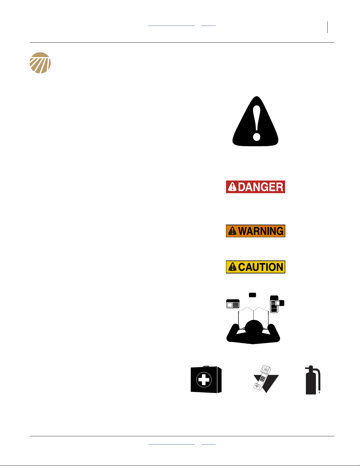
Look for Safety Symbol
The SAFETY ALERT SYMBOL indicates there is a
potential hazard to personal safety involved and extra
safety precaution must be taken. When you see this
symbol, be alert and carefully read the message that follows it. In addition to design and configuration of equipment, hazard control and accident prevention are
dependent upon the awareness, concern, prudence and
proper training of personnel involved in the operation,
transport, maintenance and storage of equipment.
Be Aware of Signal Words
Signal words designate a degree or level of hazard seriousness.
DANGER indicates an imminently hazardous situation
which, if not avoided, will result in death or serious injury.
This signal word is limited to the most extreme situations,
typically for machine components that, for functional purposes, cannot be guarded.
WARNING indicates a potentially hazardous situation
which, if not avoided, could result in death or serious
injury, and includes hazards that are exposed when
guards are removed. It may also be used to alert against
unsafe practices.
CAUTION indicates a potentially hazardous situation
which, if not avoided, may result in minor or moderate
injury. It may also be used to alert against unsafe practices.
Be Familiar with Safety Decals
▲ Read and understand “Safety Decals” on page 6, thor-
oughly.
▲ Read all instructions noted on the decals.
▲ Keep decals clean. Replace damaged, faded and illegible
decals.
Prepare for Emergencies
▲ Be prepared if a fire starts.
▲ Keep a first aid kit and fire extinguisher handy.
▲ Keep emergency numbers for doctor, ambulance, hospital
and fire department near phone.
2014-02-03 Table of Contents Index 195-069M
000
112
911
999
Page 6
2 2S-2600HD Table of Contents Index Great Plains Manufacturing, Inc.
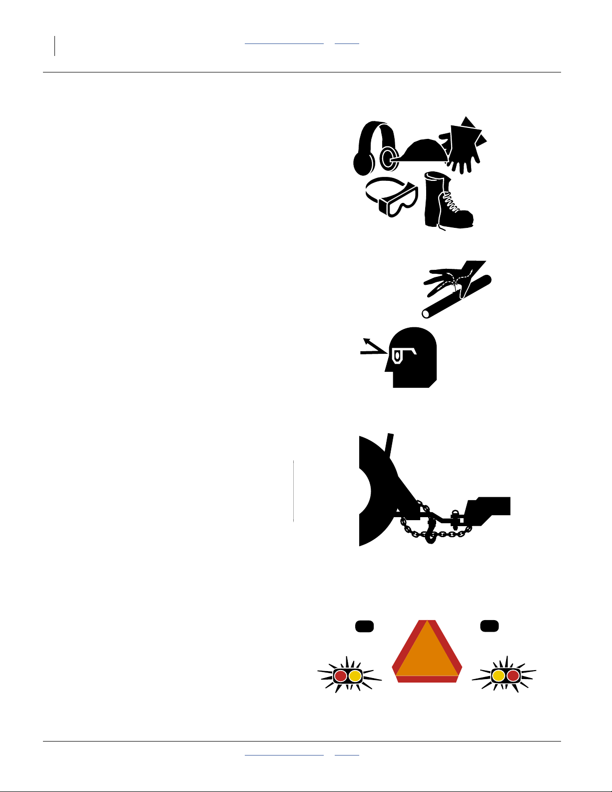
Wear Protective Equipment
▲ Wear protective clothing and equipment.
▲ Wear clothing and equipment appropriate for the job. Avoid
loose-fitting clothing.
▲ Because prolonged exposure to loud noise can cause hear-
ing impairment or hearing loss, wear suitable hearing protection such as earmuffs or earplugs.
▲ Because operating equipment safely requires your full
attention, avoid wearing entertainment headphones while
operating machinery.
Avoid High Pressure Fluids
Escaping fluid under pressure can penetrate the skin,
causing serious injury.
▲ Avoid the hazard by relieving pressure before disconnecting
hydraulic lines.
▲ Use a piece of paper or cardboard, NOT BODY PARTS, to
check for suspected leaks.
▲ Wear protective gloves and safety glasses or goggles when
working with hydraulic systems.
▲ If an accident occurs, seek immediate medical attention
from a physician familiar with this type of injury.
Use A Safety Chain
▲ Use a safety chain to help control drawn machinery should
it separate from tractor drawbar.
▲ Use a chain with a strength rating equal to or greater than
the gross weight of towed machinery.
▲ Attach chain to tractor drawbar support or other specified
anchor location. Allow only enough slack in chain to permit
turning.
▲ Replace chain if any links or end fittings are broken,
stretched or damaged.
▲ Do not use safety chain for towing.
Use Safety Lights and Devices
Slow-moving tractors and towed implements can create
a hazard when driven on public roads. They are difficult
to see, especially at night.
▲ Use flashing warning lights and turn signals whenever driv-
ing on public roads.
▲ Use lights and devices provided with the drill.
195-069M Table of Contents Index 2014-02-03
Page 7
Great Plains Manufacturing, Inc. Table of Contents Index Important Safety Information 3
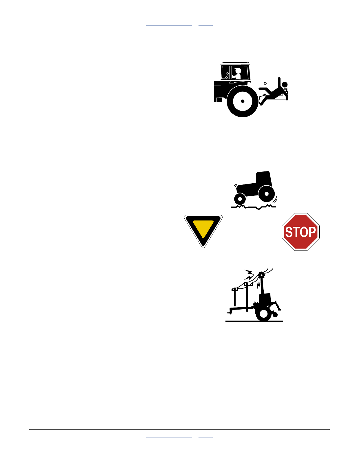
Keep Riders Off Machinery
Riders obstruct the operator’s view. Riders could be
struck by foreign objects or thrown from the machine.
▲ Never allow children to operate equipment.
▲ Keep all bystanders away from machine when fold-
ing/unfolding, raising/lowering markers, raising/lowering
openers, and transporting.
Transport Machinery Safely
Maximum transport speed for drill is 20 mph (32 kph).
Some rough terrains require a slower speed. Sudden
braking can cause a towed load to swerve and upset.
▲ Do not exceed 20 mph (32 kph). Never travel at a speed
which does not allow adequate control of steering and stopping. Reduce speed if towed load is not equipped with
brakes.
▲ Comply with national, regional and local laws.
▲ Follow your tractor manual recommendations for maximum
hitch loads. Insufficient weight on tractor steering wheels
will result in loss of control.
▲ Carry reflectors or flags to mark drill in case of breakdown
on the road.
▲ Keep clear of overhead power lines and other obstructions
when transporting. Refer to transport dimensions under
“Specifications and Capacities” on page 104.
Check for Overhead Lines
Drill markers contacting overhead electrical lines can
introduce lethal voltage levels on drill and tractor frames.
A person touching almost any metal part can complete
the circuit to ground, resulting in serious injury or death.
At higher voltages, electrocution can occur without direct
contact.
▲ Avoid overhead lines during seed loading/unloading and
marker operations.
2014-02-03 Table of Contents Index 195-069M
Page 8
4 2S-2600HD Table of Contents Index Great Plains Manufacturing, Inc.
Handle Chemicals Properly
Agricultural chemicals can be dangerous. Improper use
can seriously injure persons, animals, plants, soil and
property.
▲ Do not use liquid treatments with drill.
▲ Read and follow chemical manufacturer’s instructions.
▲ Wear protective clothing.
▲ Handle all chemicals with care.
▲ Avoid inhaling smoke from any type of chemical fire.
▲ Never drain, rinse or wash dispensers within 100 feet (30m)
of a freshwater source, nor at a car wash.
▲ Store or dispose of unused chemicals as specified by chemi-
cal manufacturer.
▲ Dispose of empty chemical containers properly. Laws gen-
erally require power rinsing or rinsing three times, followed
by perforation of the container to prevent re-use.
Shutdown and Storage
▲ Clean out and safely store or dispose of residual chemicals.
▲ Secure drill using blocks and transport locks.
Lock up openers.
▲ Store in an area where children normally do not play.
Practice Safe Maintenance
▲ Understand procedure before doing work. Use proper tools
and equipment. Refer to this manual for additional information.
▲ Work in a clean, dry area.
▲ Put tractor in park, turn off engine, and remove key before
performing maintenance.
▲ Make sure all moving parts have stopped and all system
pressure is relieved.
▲ Disconnect battery ground cable (-) before servicing or
adjusting electrical systems or before welding on drill.
▲ Inspect all parts. Make sure parts are in good condition and
installed properly.
▲ Remove buildup of grease, oil or debris.
OFF
OFF
▲ Remove all tools and unused parts from drill before opera-
tion.
195-069M Table of Contents Index 2014-02-03
Page 9

Great Plains Manufacturing, Inc. Table of Contents Index Important Safety Information 5
Tire Safety
Tire changing can be dangerous and should be performed by trained personnel using correct tools and
equipment.
▲ When inflating tires, use a clip-on chuck and extension hose
long enough for you to stand to one side–not in front of or
over tire assembly. Use a safety cage if available.
▲ When removing and installing wheels, use wheel-handling
equipment adequate for weight involved.
Safety At All Times
Thoroughly read and understand the instructions in this
manual before operation. Read all instructions noted on
the safety decals.
▲ Be familiar with all drill functions.
▲ Operate machinery from the driver’s seat only.
▲ Do not leave drill unattended with tractor engine running.
▲ Do not dismount a moving tractor. Dismounting a moving
tractor could cause serious injury or death.
▲ Do not stand between the tractor and drill during hitching.
▲ Keep hands, feet and clothing away from power-driven
parts.
▲ Wear snug-fitting clothing to avoid entanglement with mov-
ing parts.
▲ Watch out for wires, trees, etc., when folding and raising
drill. Make sure all persons are clear of working area.
▲ Do not turn tractor too tightly, causing drill to ride up on
wheels. This could cause personal injury or equipment
damage.
2014-02-03 Table of Contents Index 195-069M
Page 10
6 2S-2600HD Table of Contents Index Great Plains Manufacturing, Inc.
Safety Decals
Safety Reflectors and Decals
Your drill comes equipped with all lights, safety reflectors
and decals in place. They were designed to help you
safely operate your drill.
▲ Read and follow decal directions.
▲ Keep lights in operating condition.
▲ Keep all safety decals clean and legible.
▲ Replace all damaged or missing decals. Order new decals
from your Great Plains dealer. Refer to this section for
proper decal placement.
▲ When ordering new parts or components, also request cor-
responding safety decals.
To install new decals:
1. Clean the area on which the decal is to be placed.
2. Peel backing from decal. Press firmly on surface,
being careful not to cause air bubbles under decal.
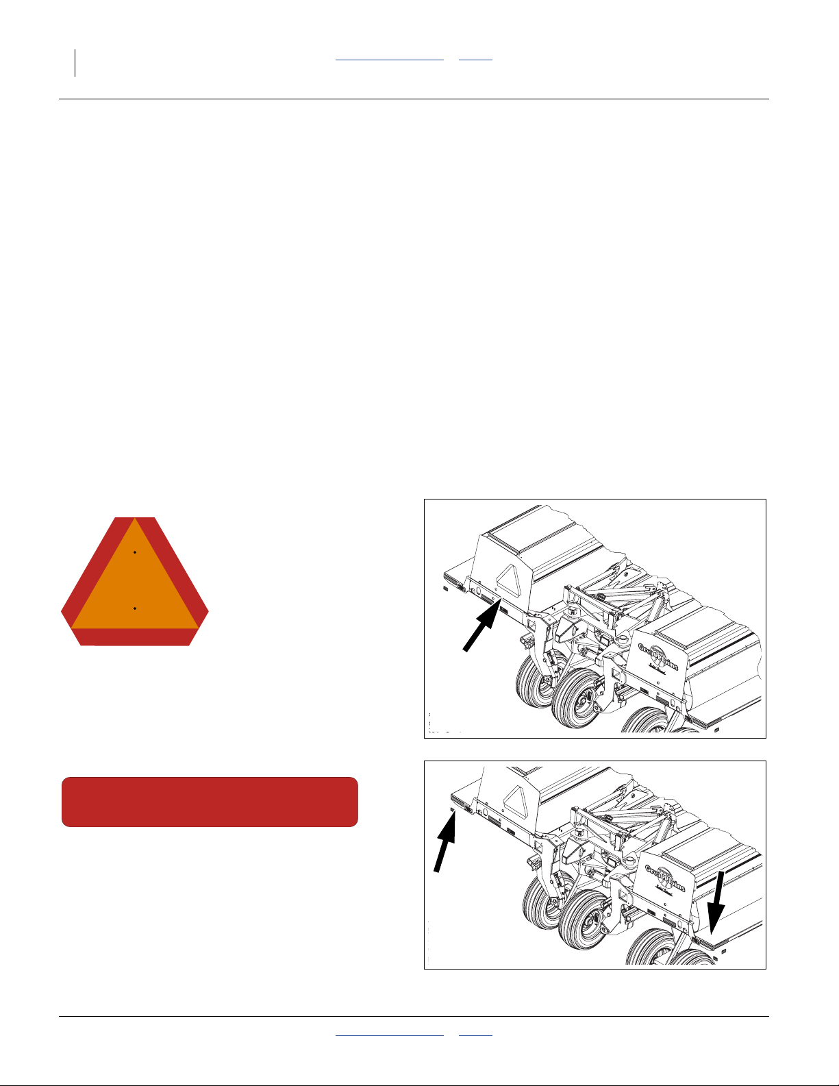
818-055C
Slow Moving Vehicle Reflector
Right end panel of left main seed box;
1 total
838-266C
Red Reflectors
On wing walkboard inside end faces
(outside rear corners in transport);
2 total
26445
26445
195-069M Table of Contents Index 2014-02-03
Page 11
Great Plains Manufacturing, Inc. Table of Contents Index Important Safety Information 7
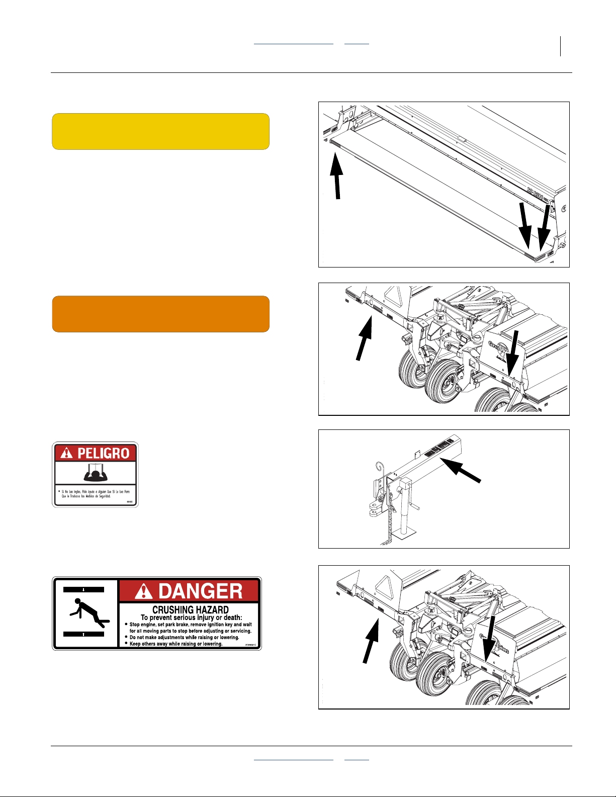
838-265C
Amber Reflectors
On wing walkboard rear faces, outside corners,
on outside end face of wing walkboards,
6 total
26445
838-267C
Daytime Reflectors
On inside wing frames below seed boxes
(inboard of red reflectors);
2 total
818-557C
Danger: Cannot Read English
On tongue at hitch;
1 total
818-864C
26445
26445
Danger: Pinch/Crush Hazard
Inside wing frames below seed boxes
(inboard of daytime reflectors);
2 total
2014-02-03 Table of Contents Index 195-069M
26445
Page 12
8 2S-2600HD Table of Contents Index Great Plains Manufacturing, Inc.
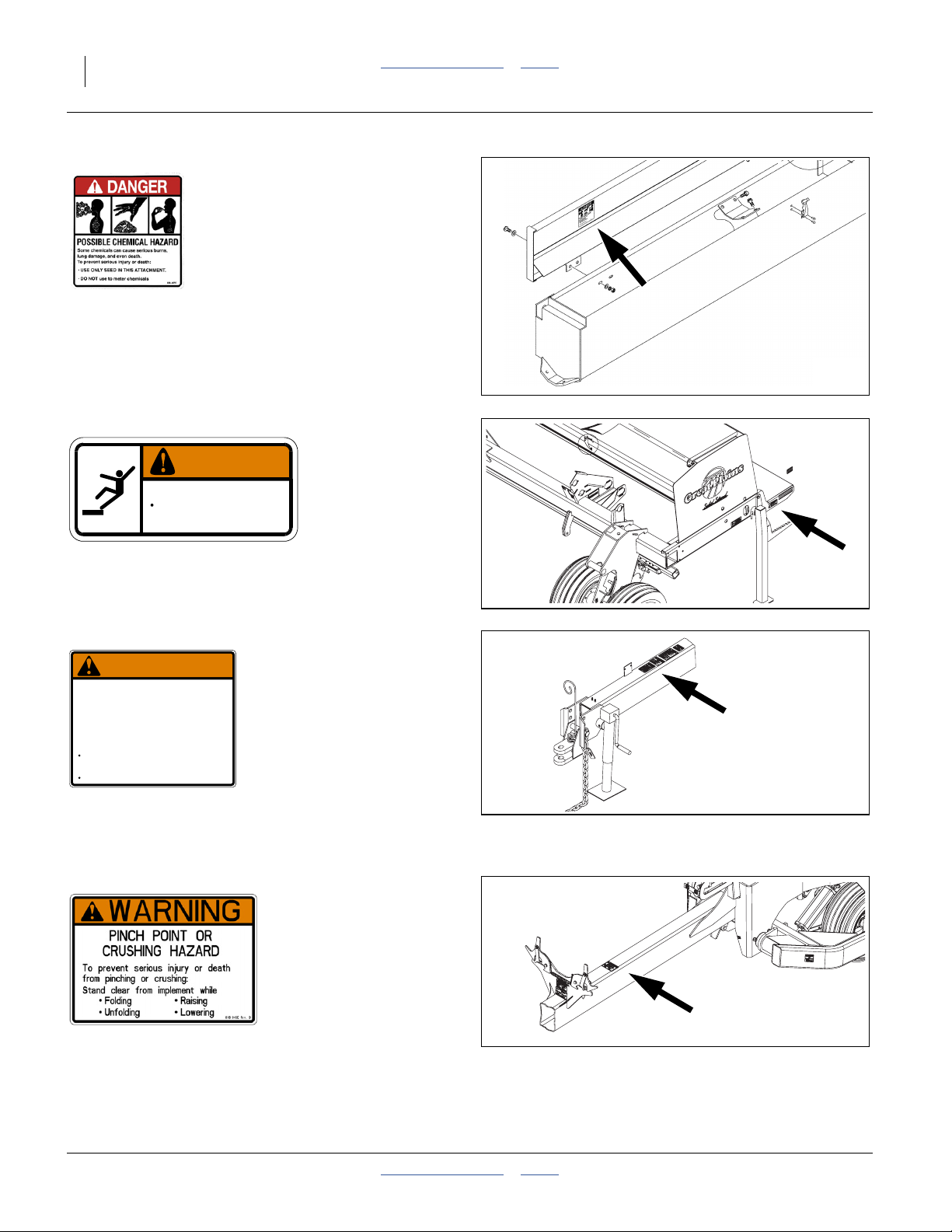
838-467C
Danger: Possible Chemical Hazard
Inside lid of optional Small Seeds box left hand side,
one each box;
2 total
21730
838-102C
WARNING
To avoid serious injury or death:
Watch your step when climbing ladder or
walking on walkboard.
838-102C
Warning: Falling Hazard
On outside walkboard end above step;
2 total
818-019C
WARNING
NEGATIVE TONGUE WEIGHT
Negative tongue weight can cause immediate
elevation of tongue when unhitching implement
Warning: Negative Tongue Weight
On tongue at hitch;
1 total
818-045C
HAZARD
To prevent serious injury or death:
Always be certain implement is hitched securely
to tractor drawbar before raising.
Lower implement BEFORE unhitching.
818-019C Rev. D
26445
26445
26445
Warning: Pinch/Crush Hazard
On tongue near transport locks,
(inboard of daytime reflectors);
1 total
195-069M Table of Contents Index 2014-02-03
Page 13
Great Plains Manufacturing, Inc. Table of Contents Index Important Safety Information 9
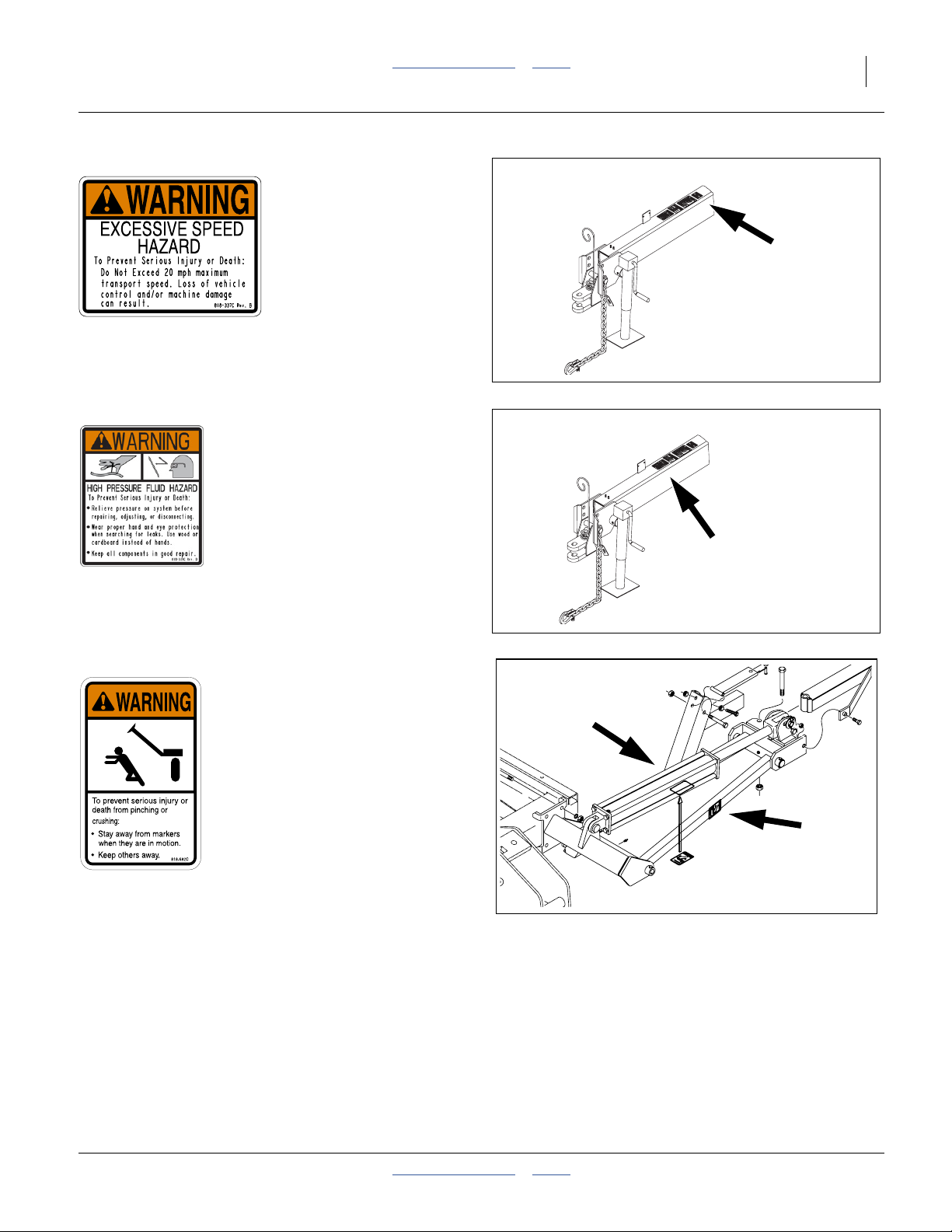
818-337C
Warning: Excessive Speed Hazard
On tongue near hitch;
1 total
26445
818-339C
Warning: High Pressure Fluid
On tongue near hitch;
1 total
818-682C
Warning: Marker Pinch Crush
On front and outside faces of first marker section,
two each marker installed;
2 or 4 total
26445
26497
2014-02-03 Table of Contents Index 195-069M
Page 14
10 2S-2600HD Table of Contents Index Great Plains Manufacturing, Inc.
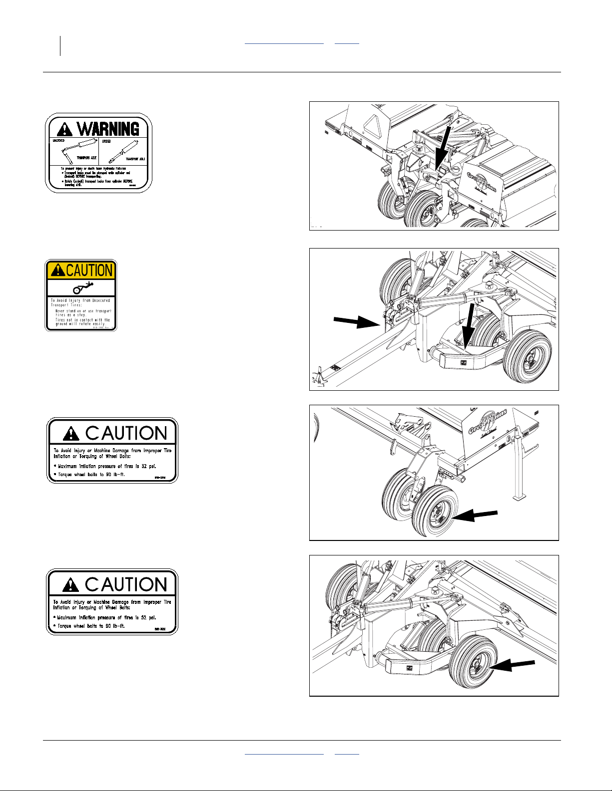
818-861C
Warning: Transport Locks
On rear of mainframe;
1 total
26445
818-398C
Caution: Tires Not A Step
On each axle leg (transport wheels);
2 total
818-751C
Caution: 32 PSI Tire Pressure
On rim of each gauge wheel;
4 total
26445
26445
818-752C
Caution: 52 PSI Tire Pressure
On rim of each transport wheel;
4 total
195-069M Table of Contents Index 2014-02-03
26445
Page 15
Great Plains Manufacturing, Inc. Table of Contents Index 11
Introduction
Great Plains welcomes you to its growing family of new
product owners. Your 26-Foot Two-Section Folding HD
Drill has been designed with care and built by skilled
workers using quality materials. Proper setup, maintenance, and safe operating practices will help you get
years of satisfactory use from the machine.
Document Family
195-069M Owner’s Manual (this document)
195-069P 2S-2600HD Parts Manual
195-069B Seed Rate Manual
Description of Unit
The 2S-2600HD is a towed seeding implement. This two
section drill has a working width of 26 feet (8m). The drill
has straight arm, double disk heavy duty openers. The
opener disks make a seed bed, and seed tubes mounted
between the disks place seed in the furrow. Press
wheels following the opener disks close the furrow and
gauge opener seeding depth. A T-handle on the opener
body is for seeding depth adjustments. Seeding rates are
adjustable with the seed rate adjustment handle and
sprocket changes.
The 2S-2600HD features active hydraulic down pressure
on the opener frames. When used on a tractor with
closed-center hydraulics, constant down pressure
ensures even opener penetration in uneven ground.
Hydraulic down pressure is adjustable at a single point.
Intended Usage
Use this implement to seed production-agriculture crops
in conventional or minimum tillage applications.
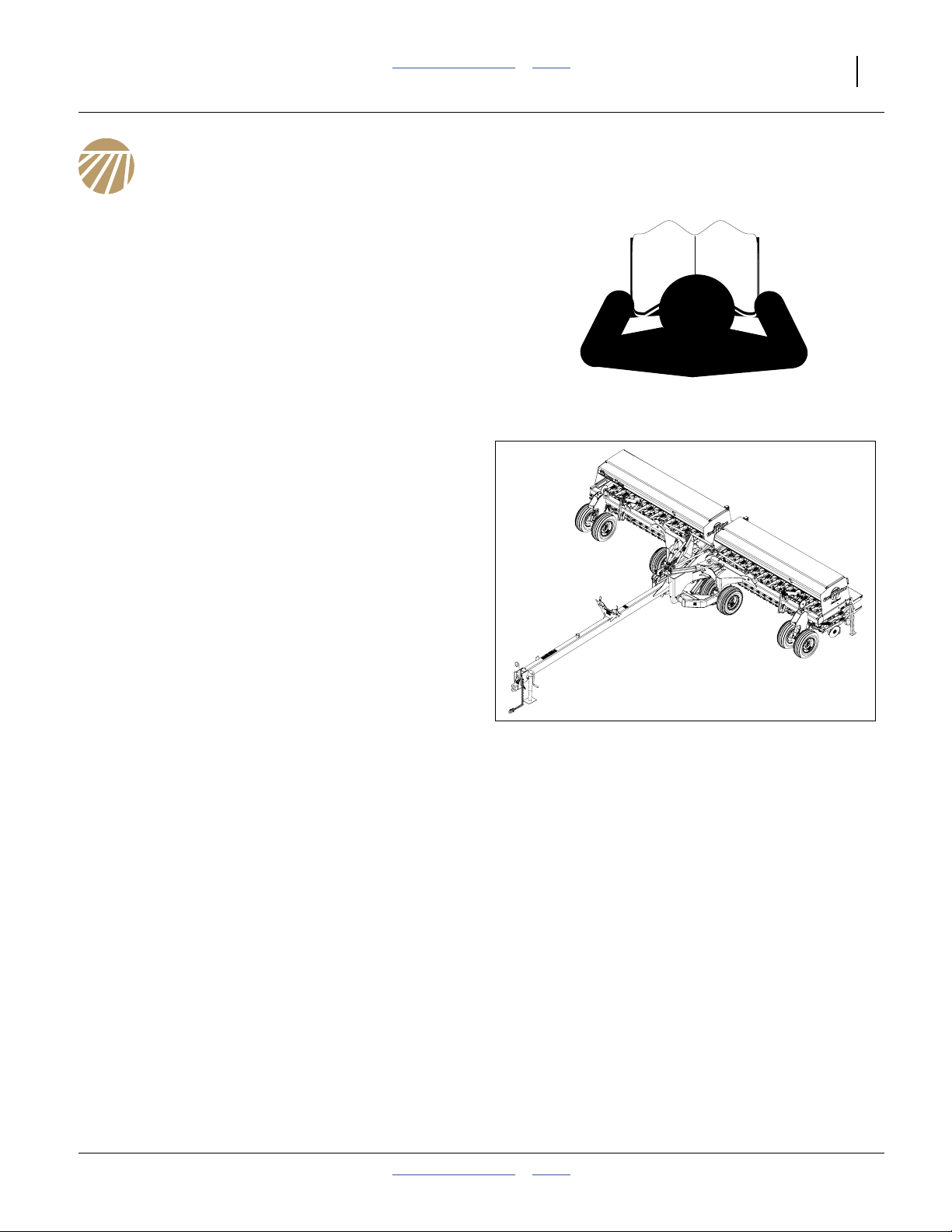
Figure 1
2S-2600HD Drill
17254
Models Covered
HD Models have 00HD Series Heavy Duty openers and
a main seed box used entirely for seed. HDF Models add
fertilizer meters and divide the main box for this purpose.
Standard HD models may add optional Small Seeds
capability.
2S-2600HD-3210 32-row, 10in (24.5cm)
2S-2600HD-4275 42-row, 7.5in (19cm)
2S-2600HD-5206 52-row, 6in (15cm)
2S2600HDF-3210 32-row, 10in (24.5cm)
2S2600HDF-4275 42-row, 7.5in (19cm)
2S2600HDF-5206 52-row, 6in (15cm)
2014-02-03 Table of Contents Index 195-069M
Page 16
12 2S-2600HD Table of Contents Index Great Plains Manufacturing, Inc.
Using This Manual
This manual familiarizes you with safety, assembly, operation, adjustments, troubleshooting, and maintenance.
Read this manual and follow the recommendations to
help ensure safe and efficient operation.
The information in this manual is current at printing.
Some parts may change to assure top performance.
R
Definitions
The following terms are used throughout this manual.
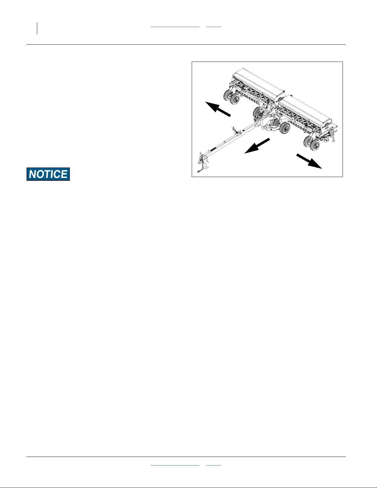
Right-hand and left-hand as used in this manual are
determined by facing the direction the machine will travel
while in use unless otherwise stated.
L
Paragraphs in this format present a crucial point of information
related to the current topic.
Figure 2
Left/Right Notation
17254
Read and follow the directions to:
- remain safe,
- avoid serious damage to equipment and
- ensure desired field results.
Note: Paragraphs in this format provide useful informa-
tion related to the current topic.
195-069M Table of Contents Index 2014-02-03
Page 17
Great Plains Manufacturing, Inc. Table of Contents Index Introduction 13
Owner Assistance
If you need customer service or repair parts, contact a
Great Plains dealer. They have trained personnel, repair
parts and equipment specially designed for Great Plains
products.
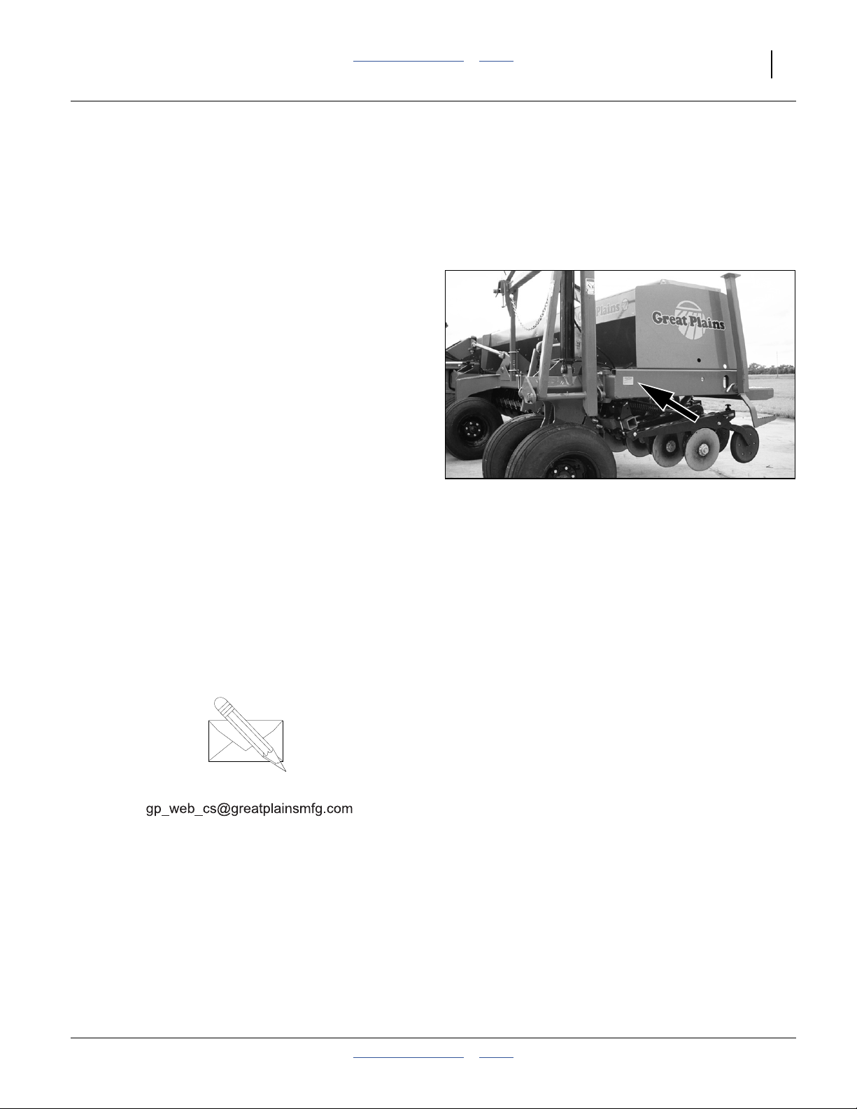
Refer to Figure 3
Your machine’s parts were specially designed and
should only be replaced with Great Plains parts. Always
use the serial and model number when ordering parts
from your Great Plains dealer. The serial-number plate is
located on the left side of the drill frame below the front
of the seed box.
Record your drill model and serial number here for quick
reference:
Model Number:__________________________
Serial Number: __________________________
Your Great Plains dealer wants you to be satisfied with
your new machine. If you do not understand any part of
this manual or are not satisfied with the service received,
please take the following actions.
1. Discuss the matter with your dealership service
manager. Make sure they are aware of any problems
so they can assist you.
2. If you are still unsatisfied, seek out the owner or general manager of the dealership.
For further assistance write to:
Figure 3
Serial Number Plate
17315
Product Support
Great Plains Mfg. Inc., Service Department
Salina, KS 67402-5060
PO Box 5060
785-823-3276
2014-02-03 Table of Contents Index 195-069M
Page 18

14 2S-2600HD Table of Contents Index Great Plains Manufacturing, Inc.
Preparation and Setup
This section helps you prepare your tractor and drill for
use. Before using the drill in the field, you must hitch the
drill to a suitable tractor and also setup the drill.
Pre-Setup Checklist
1. Read and understand “Important Safety Information” on page 1.
2. Check that all working parts are moving freely, bolts
are tight, and cotter pins are spread.
3. Check that all grease fittings are in place and lubricated. See “Lubrication” on page 91.
4. Check that all safety decals and reflectors are correctly located and legible. Replace if damaged. See
“Safety Decals” on page 6.
5. Inflate tires to pressure recommended and tighten
wheel bolts as specified. “Appendix A” on page 104.
Hitching
Crushing Hazard:
You may be severely injured or killed by being crushed
between the tractor and drill. Do not stand or place any part of
your body between machines being hitched. Stop tractor
engine and set park brake before installing hitch pins.
Transport Hazard:
This drill can have positive and negative tongue weight, which
can work the hitch pin loose during transport. To avoid serious
injury or death due to a road accident, always use a clevis
hitch or clevis drawbar with a locking-style hitch pin.
Choose a drill-hitch option (page 99) that is compatible
with your tractor drawbar.
The 2S-2600HD has three hitch options:
• a clevis hitch,
• a small-hole, single-strap hitch or;
• a large-hole, single-strap hitch.
Use the clevis hitch with tractors that have single-tang
drawbars. Use the single-strap hitch for tractors with clevis drawbars. Always use a locking-style hitch pin sized
to match the holes in the hitch and drawbar.
195-069M Table of Contents Index 2014-02-03
Page 19
Great Plains Manufacturing, Inc. Table of Contents Index Preparation and Setup 15
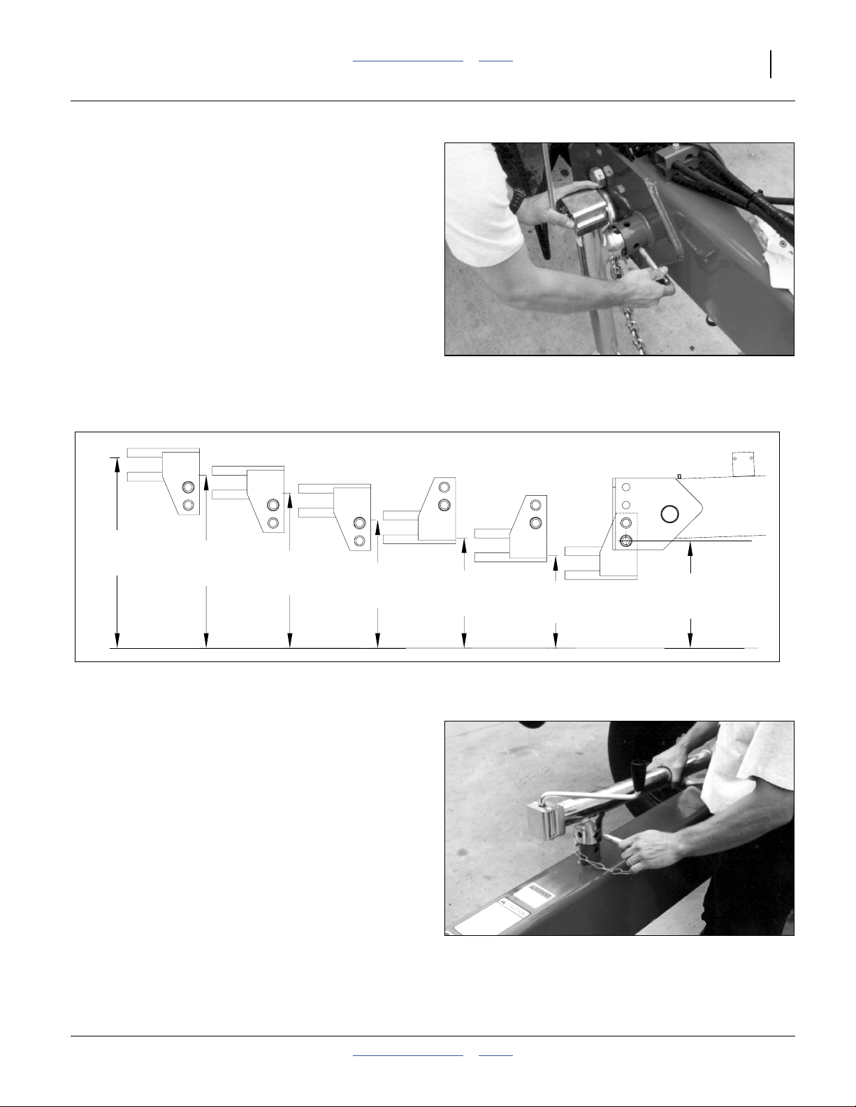
Refer to Figure 4 and Figure 5
To adjust the drill hitch to match your tractor-drawbar
height, mount tongue jack on side of tongue. Use jack to
raise drill tongue so lowest hitch hole is 18 inches
(45.7cm) above ground level with drill lowered to FIELD
position.
Refer to Figure 5
Bolt drill hitch onto drill tongue to match your tractor-drawbar height. You can turn the hitch over for a total
of six different hitch heights. Always have two (2) bolts in
two holes of both tongue and hitch.
Note: When hitching drill to a different tractor, check for a
difference in drawbar heights. If heights are different, readjust hitch height accordingly.
Securely attach safety chain to an anchor on a tractor
Figure 4
Jack in Lifting Location
15564
capable of pulling the drill.
32.0in
81.3cm
29.0in
73.7cm
26.0in
66.0cm
21.5in
54.6cm
Figure 5
Heights for Various Hitch Positions - Correct Tongue Height
Refer to Figure 6
Use crank to raise jack foot. Remove pin and jack. Store
jack on top of tongue.
18.5in
47.0cm
15.5in
39.4cm
18.0in
45.7cm
15623
Figure 6
15563
Jack in Storage Location
2014-02-03 Table of Contents Index 195-069M
Page 20
16 2S-2600HD Table of Contents Index Great Plains Manufacturing, Inc.
Electrical Connections
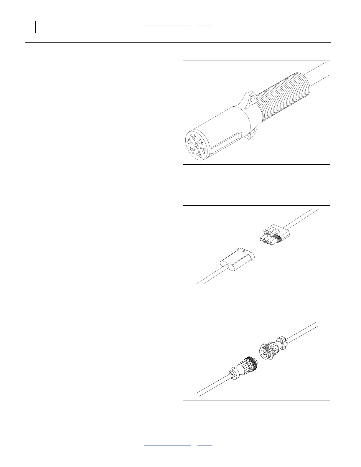
Refer to Figure 7
Plug drill electrical lead into tractor seven-pin connector.
If your tractor is not equipped with a seven-pin connector,
contact your dealer for installation.
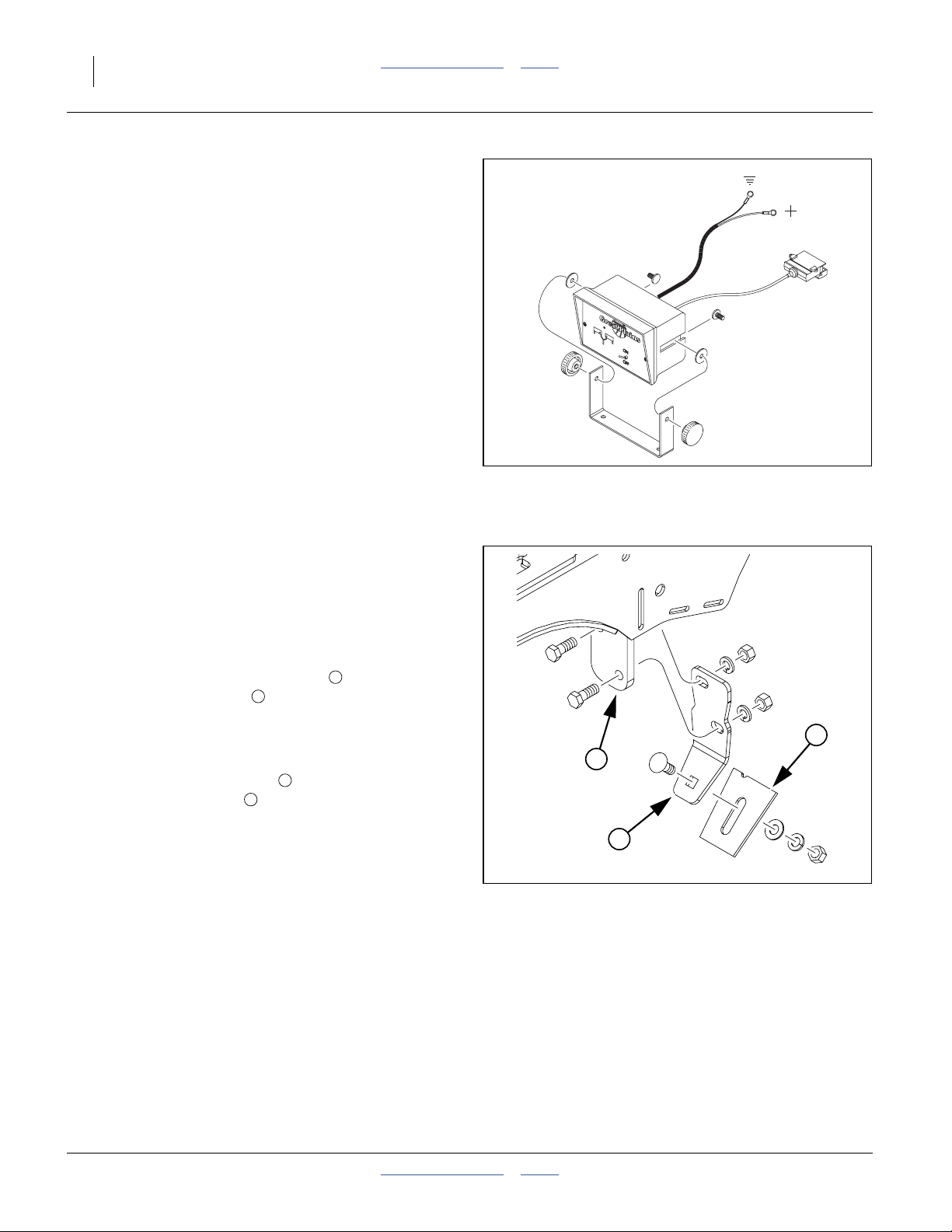
Refer to Figure 8
If the drill is equipped with the optional shaft monitor,
mate the connector for the cab display.
See “Shaft Monitor” on page 100 for ordering information.
Refer to Figure 9
If the drill is equipped with the point row option, mate the
connector for the cab control.
See “Point Row Clutch” on page 100 for ordering information.
Figure 7
Lighting Connector
Figure 8
Shaft Monitor Connector
26467
34221
Figure 9
26469
Point-Row Connector
195-069M Table of Contents Index 2014-02-03
Page 21
Great Plains Manufacturing, Inc. Table of Contents Index Preparation and Setup 17
Hydraulic Hose Hookup
High Pressure Fluid Hazard:
Only trained personnel should work on system hydraulics!
Escaping fluid under pressure can have sufficient pressure to
penetrate the skin, causing serious injury. Avoid the hazard by
relieving pressure before disconnecting hydraulic lines. Use a
piece of paper or cardboard, NOT BODY PARTS, to check for
leaks. Wear protective gloves and safety glasses or goggles
when working with hydraulic systems. If an accident occurs,
seek immediate medical attention from a physician familiar
with this type of injury.
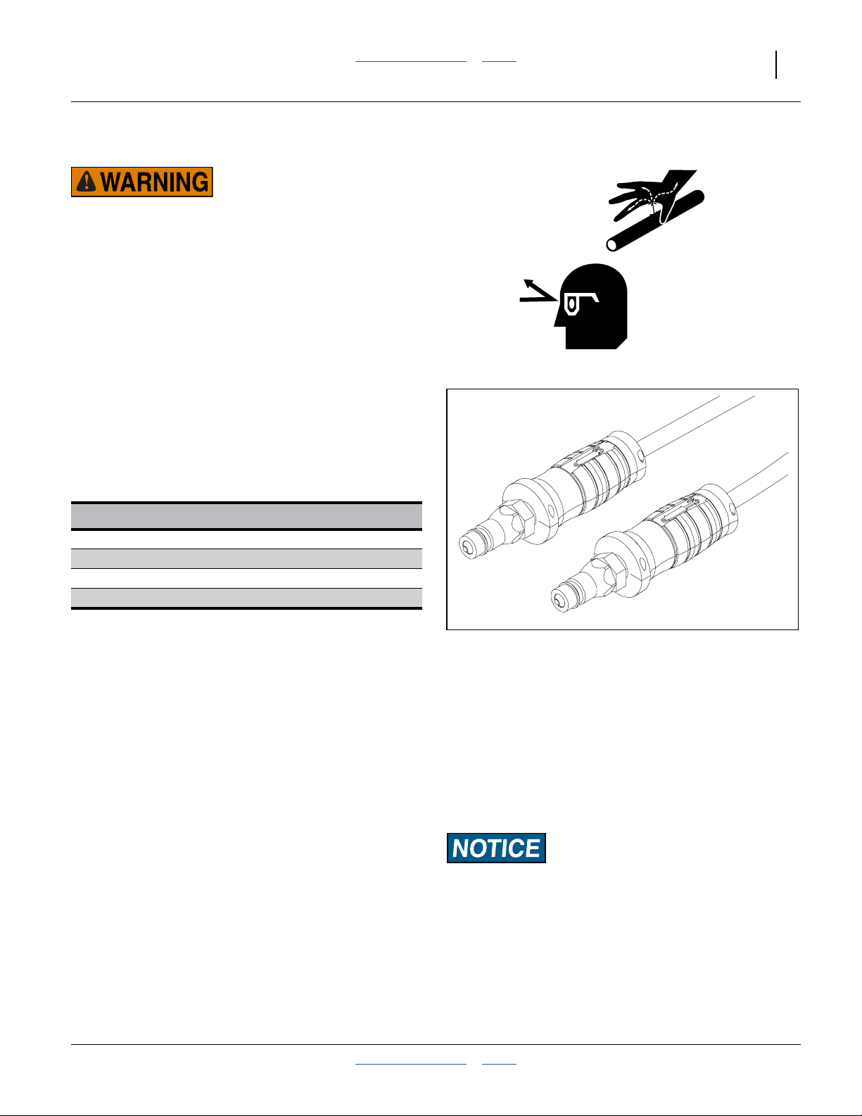
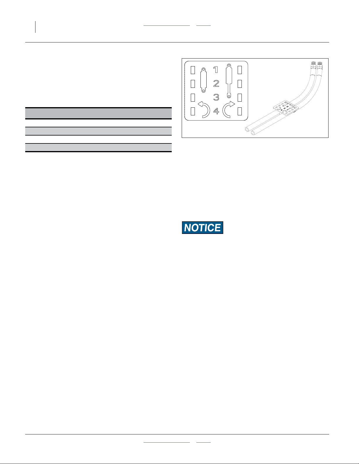
Refer to Figure 10
Great Plains hydraulic hoses are color coded handle
grips to help you hookup hoses to your tractor outlets.
Hoses that go to the same remote valve are marked with
the same color.
Current Style Color Coded Hose Handles.
Color Hydraulic Function
Red Opener Lift Cylinders
Blue Transport Lift Cylinders
Gray Fold Cylinders
Green Marker Cylinders
To distinguish hoses on the same hydraulic circuit, refer
to the symbol molded into the handle grip. Hoses with an
extended-cylinder symbol feed cylinder base ends.
Hoses with a retracted-cylinder symbol feed cylinder rod
ends.
1. Connect opener-lift hoses to circuit designated for
hydraulic-motor control.
2. Connect transport-lift hoses to tractor remote valve.
3. Connect fold hoses to tractor remote valve.
4. Connect marker hoses to tractor remote valve.
Note: If your tractor has only two remote valves, you must
install a double-selector valve to combine the transport-lift and opener-lift circuits. See “Two Outlet
Hydraulic Kit” on page 99.
Figure 10
Color Coded Hose Grips
To run drill on tractors with open-center hydraulics or on
tractors with fixed-displacement hydraulic pumps, you must
install a Great Plains kit, part number 194-143A. If you are
not familiar with your tractor hydraulics, consult your tractor dealer.
31733
2014-02-03 Table of Contents Index 195-069M
Page 22
18 2S-2600HD Table of Contents Index Great Plains Manufacturing, Inc.
Older Style Hoses with Color Ties
Refer to Figure 11
Great Plains hydraulic hoses are color coded to help you
hookup hoses to your tractor outlets. Hoses that go to
the same remote valve are marked with the same color
tie.
Color Hydraulic Function
Red Opener Lift Cylinders
Blue Transport Lift Cylinders
White Fold Cylinders
Orange Marker Cylinders
To distinguish hoses on the same hydraulic circuit, refer
to plastic hose label. The hose under an extended-cylinder symbol feeds a cylinder base end. The hose under a
retracted-cylinder symbol feeds a cylinder rod end.
1. Connect opener-lift hoses to circuit designated for
hydraulic-motor control.
2. Connect transport-lift hoses to tractor remote valve.
3. Connect fold hoses to tractor remote valve.
4. Connect marker hoses to tractor remote valve.
Note: If your tractor has only two remote valves, you must
install a double-selector valve to combine the transport-lift and opener-lift circuits. See “Two Outlet
Hydraulic Kit” on page 99.
Check Drill Level
These items are set and verified at the factory, but need
to be checked prior to first use.
•“Opener Frames Level” on page 84
•“Link Tube” on page 85
•“Wing Box Alignment” on page 86
•“Tool Bar Height” on page 85
Figure 11
Older Style Hoses with Label
To run drill on tractors with open-center hydraulics or on
tractors with fixed-displacement hydraulic pumps, you must
install a Great Plains kit, part number 194-143A. If you are
not familiar with your tractor hydraulics, consult your tractor dealer.
817-348c
17641
195-069M Table of Contents Index 2014-02-03
Page 23

Great Plains Manufacturing, Inc. Table of Contents Index Preparation and Setup 19
Setting the Bypass Valve
1
Refer to Figure 12
A bypass valve is plumbed into the opener down pressure circuit. Tractors with load-sensing, closed-center
hydraulics require this bypass valve to protect the tractor
hydraulic system. If you are unsure what type of hydraulic system is on your tractor, contact your tractor manufacturer.
“CENTER” are the two inside opener lift cylinders.
“WING” are the two outside opener lift cylinders.
If the Point Row option is installed, these controls are
re-plumbed as entire “LEFT” and “RIGHT” wings.
1
2
3
Turn the locking disc counter-clockwise to enable
adjustment. Turn the adjustment knob counter-clock-
wise to increase flow.
Turn the adjustment knob clockwise to decrease flow.
Turning it fully clockwise stops all bypass flow.
2
3
3
Tractors with Open Center Hydraulics
Release locking disc. Close bypass valve for no oil flow
by turning knob on valve clockwise completely. Tighten
locking disc. Always operate the drill with the bypass
valve locked closed.
Tractors with Pressure Compensating Closed Center Hydraulics (PC Closed)
Release locking disc. Close bypass valve for no oil flow
by turning knob clockwise completely. Tighten locking
disc. Always operate the drill with the bypass valve
locked closed.
Tractors with Load Sensing Closed Center Hydraulics (LS Closed) or Pressure Flow Compensating (PFC) Systems
1. Release locking disc. Initially close bypass valve for
no oil flow by turning knob on valve clockwise completely.
2. With tractor at half throttle, adjust flow-control valve
on tractor so openers raise and lower at a reasonable speed. Keep tractor at one-half throttle for
remaining steps.
Note: The faster openers raise and lower, the greater po-
tential for oil heating, premature wear or tractor
damage.
3. Engage tractor hydraulics and lower openers. Lock
hydraulic lever on tractor for continuous operation.
See “Raising and Lowering Openers” on page 24.
Figure 12
Bypass Valve
Equipment Damage Risk:
Failure to use the bypass valve on load-sensing tractors may
cause major tractor damage.
19045
2014-02-03 Table of Contents Index 195-069M
Page 24

20 2S-2600HD Table of Contents Index Great Plains Manufacturing, Inc.
Refer to Figure 12 on page 19 and Figure 13 at right
4. Release locking discs on down-pressure valves.
Adjust knobs on pressure-control valves for
opener down pressure so gauges are at 1500 psi.
5. While watching gauges on drill, slowly turn knob on
bypass valve counterclockwise. Adjust bypass valve
just until needles on gauges begin to move down
from 1500 psi. Lock bypass valve at this setting.
(See also note below.)
6. Re-adjust pressure-control valves on drill to desired
opener down pressure as explained under See
“Opener Frame Down-Force” on page 62.
Note: The higher the bypass pressure, the greater the po-
tential for oil heating and premature tractor damage. At the same time, for proper opener operation
the bypass valve must be set at least 100 psi above
the opener down-pressure setting when the tractor
is at one-half throttle. Therefore, you should set the
bypass valve as low as possible while staying at
least 100 psi above the opener down pressure setting.
While 1500 psi is a good starting point for setting the
bypass valve, if you consistently operate the drill with low
opener down pressure you can set the bypass valve
below 2100 psi. If you consistently operate the drill with
very high opener down pressure, you may need a
bypass-valve setting above 2100 psi. See also
“Opener-Subframe Adjustment” on page 64.
6
5
4
4
5
6
Figure 13
Down Pressure for Bypass
26471
Adjusting the Counter Balance Valve
On the stem of the valve there is a rubber cap that protects the threads of an adjustment stem. This stem is
locked in place with a hex nut. To adjust the valve, loosen
the nut and turn the stem using an Allen wrench.
Screwing the stem in (clockwise) pushes on a spring
which supplements the pilot line’s force on an internal
piston. More spring force will let the valve open with a
low pilot pressure. Less spring force will require higher
pilot pressure to open the valve.
Note: With the screw turned in fully, the spring will
develop enough force on the piston to unlock the
valve, even with no pilot pressure, causing the
openers to settle.
Raise and lower the drill several times then hold hydraulic down pressure on the openers to purge air from the
system and to warm the oil. Repeat.
Raise the openers. Observe the openers closely to detect
settling. If the openers remain up, no valve adjustment is
needed.
If the openers settle, the stem is screwed in too far. Gently
back the stem out until it stops, then screw it in one turn.
Generally this is a good starting point. Check for settling.
Backing the stem out will lock the valve, screwing it in too
far can cause it to unlock.
A small increase in lowering speed can be achieved by
screwing the stem in.
195-069M Table of Contents Index 2014-02-03
Page 25

Great Plains Manufacturing, Inc. Table of Contents Index Preparation and Setup 21
Marker Setup
Refer to Figure 14
Markers are field-installed, but usually do not have their
extension length precisely set. The drill must be lev-
eled per “Leveling the Drill” on page 84, and marker(s)
must be in correct working order per “Marker Mainte-
nance” on page 87.
Row unit centerline stations on 2S-2600HD drills are
symmetrical about machine center, so left and right
extensions are normally identical, for both opposing and
concentric passes.
Set the initial length of the marker(s) as follows:
1. With drill unfolded, lower drill and openers to field
position (“Raising and Lowering Openers” on page
24).
2. Extend a marker on one side. Pull forward several
feet to leave a mark.
3. Sighting parallel to the main tool bar, measure
from the centerline of the left outside row unit to the
mark.
4. Adjust the marker extension so that the mark is
one half the span plus one row unit spacing .
See “Marker Adjustments” on page 70 for setting
marker extension.
5. Pull forward several feet, and re-measure to verify
any adjustment. Validate the mark by making a pass
to one or both sides.
6. Fold marker. Extend other side and adjust.
E
E
E
H S R
R
H
E
Figure 14
Marker Extension
Model
2S-2600HD-3210 10 in
2S-2600HD-4275 7.5 in
2S-2600HD-5206 6 in
Note: If field conditions require inverting the marker disk
(page 72), the mark moves, and the extension
needs to be re-measured and reset. Marking also
changes slightly if the opener frame trunnion position is changed (page 64).
Spacing Extension
R E
(419.1cm)
(410.8cm)
S
165.0in
161.75in
160.25in
407.0cm
Point Row Cab Module
If your drill has the Point Row option, the cab module
may already have been installed by your dealer. If not,
consult the installation instructions for the option, and
mount the module in a convenient location.
Figure 15
Point Row Cab Module
2014-02-03 Table of Contents Index 195-069M
22692
Page 26
22 2S-2600HD Table of Contents Index Great Plains Manufacturing, Inc.
Shaft Monitor Cab Module
If your drill has the Shaft Monitor option, the cab module
may already have been installed by your dealer. If not,
consult the installation instructions for the option, and
mount the module in a convenient location.
If the cab is particularly noisy, or the operator customarily
wears a noise-cancelling headset, the alarms may not be
audible. Mount the module where the status indicators
are visible during planting operations.
Scraper Installation
Optional disk scrapers are not factory installed. To install
them in the field:
1. Remove one or both disk blades to gain safe access
to the mount. Note the position of bushings and
spacers for correct re-assembly (page 67).
Refer to Figure 17
2. Position the inside scraper mount to the rear of
the seed firmer mount on the opener weldment.
Secure it with two HHCS
2
3
⁄
-16x1in hex head bolts,
8
lock washers and nuts. Insert the bolts from the front.
3. Position the scraper blade below and behind the
inside scraper mount , with the notch on top to
3
1
machine right.
Secure it loosely with one RHSNB
head square neck bolt, flat washer, lock washer and
nut.
4. Re-mount the removed disk blade.
5. Adjust the scraper blade per “Disk Scraper Adjust-
ments” on page 68.
1
3
⁄
-16x1 round
8
Figure 16
Shaft Monitor Cab Module
2
1
Figure 17
Scraper Installation
27049
3
26460
195-069M Table of Contents Index 2014-02-03
Page 27

Great Plains Manufacturing, Inc. Table of Contents Index 23
Operating Instructions
This section covers general operating procedures. It
assumes that setup items have been completed for both
drill and tractor.
Experience, machine familiarity and the following information will lead to efficient operation and good working
habits. Always operate farm machinery with safety in
mind.
General Description
On the standard 2S-2600HD, field operations are controlled by tractor cab hydraulic levers. When openers are
lowered, mechanical clutches engage, and the gauge
wheels drive the seed meter shafts. Markers, if installed,
are on a separate circuit.
If the Point Row Option is installed, openers are controlled by section (wing), and are raised and lowered by
solenoid valves operated by the point row controller.
Both Transport Lift and Opener Lift circuits must be in the
raised configuration for folding and unfolding.
Seed meters operate at a rate proportional to ground
speed, as set by Drive Type and Seed Rate Handles,
based on the Seed Rate charts, and calibration.
Seeding depth and furrow coverage are controlled by drill
down pressure and row unit setup.
2014-02-03 Table of Contents Index 195-069M
Page 28
24 2S-2600HD Table of Contents Index Great Plains Manufacturing, Inc.
Pre-Start Checklist
❑ Lubricate the drill as indicated under Lubrication,
“Maintenance and Lubrication” on page 78.
❑ Check the tires for proper inflation according to “Tire
Inflation Chart” on page 104.
❑ Check for worn or damaged parts and repair or
replace before going to the field.
❑ Check all nuts, bolts and screws. Tighten bolts as
specified on “Torque Values Chart” on page 105
Raising and Lowering Openers
Opener sub-frames are on a dedicated hydraulic circuit.
Openers raise and lower independently of the drill frame
(which is raised and lowered by the Transport Lift circuit).
When lowered, the opener circuit can use live hydraulic
power to regulate down pressure. To operate with live
power, connect the opener lift circuit to the #1 remote
hydraulic circuit or the circuit designed for HYDRAULIC
MOTOR control. On many CLOSED CENTER or PRESSURE/FLOW COMPENSATED tractors the #1 circuit is
designed to supply live hydraulic power to remotes.
On the standard 2S-2600HD drill, the openers raise and
lower as a group, from a tractor cab lever. If the Point
Row Option is installed, each section can raise and lower
independently, using switches on the point row control
module in the tractor cab.
If the Two Outlet conversion kit is installed, a selector
valve near the hitch must be operated to switch between
Opener Lift and Transport Lift. During field operations,
this valve is in the Opener Lift position.
Opener Lock Up
The openers must be raised and locked up for folding,
transporting or for working under the drill.
Negative Tongue Weight: Raising openers on unfolded,
unhitched drill will cause drill tongue to rise suddenly, which
could cause serious injury or death. Be certain that drill is
hitched securely to your tractor drawbar and the safety chain
is securely attached to tractor before raising openers and
unfolding drill.
1
2
Figure 18
Gauge Wheel Opener Lock-Up
15549
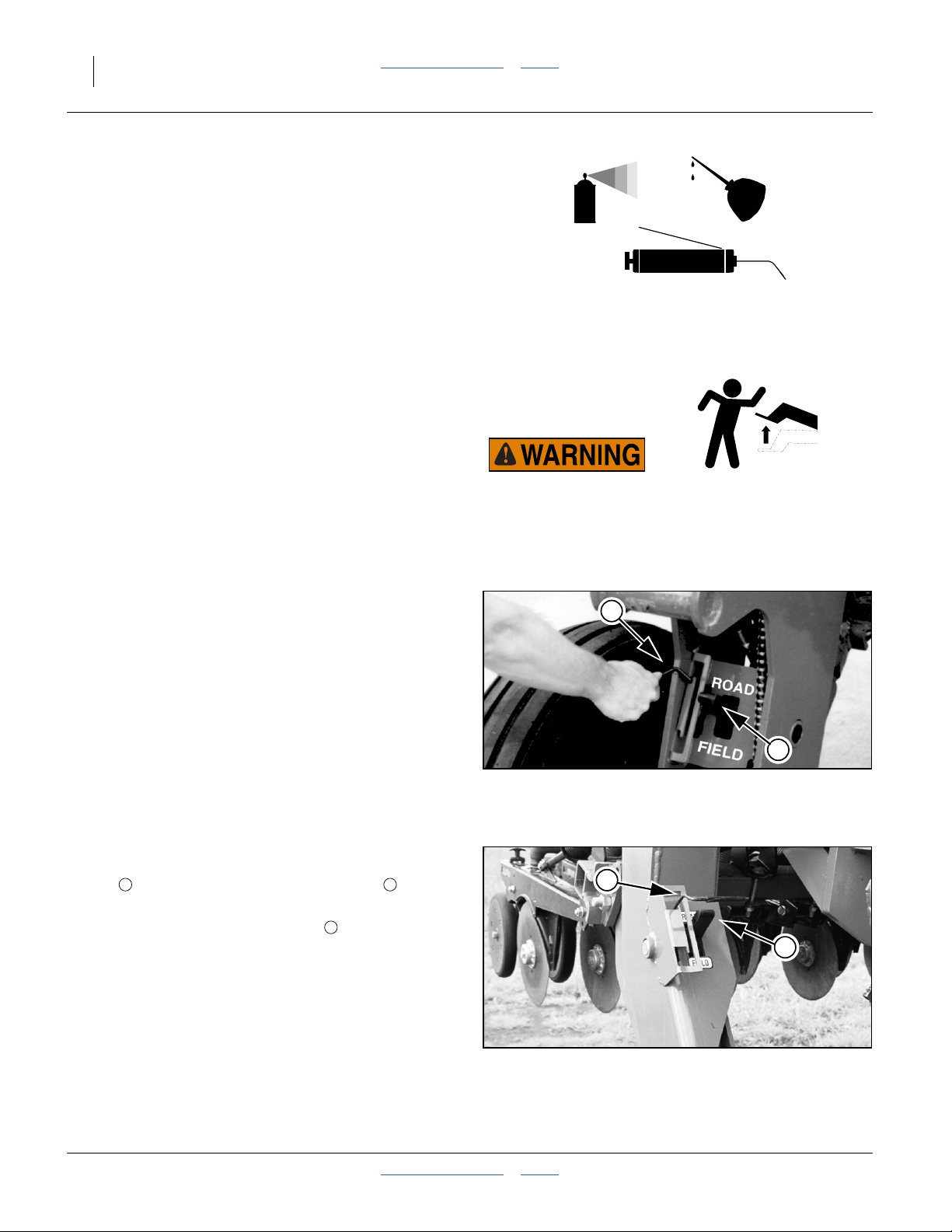
Refer to Figure 18 and Figure 19
Each of the four opener lift assemblies has wire rod lock
handle , and a cylinder lock status indicator on the
lock hook.
Note: Opener transport lock handles move with open-
Lock Up Openers
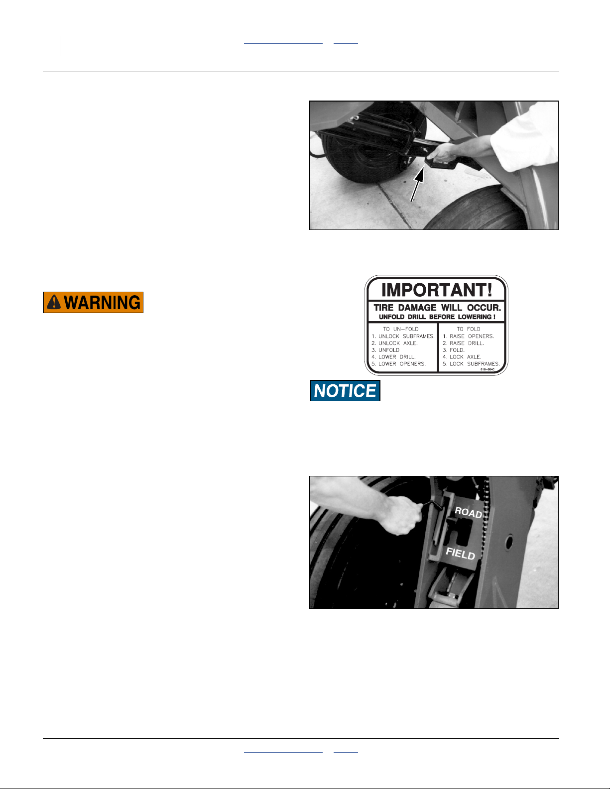
1. Position opener transport handles in ROAD position.
2. Raise openers completely.
195-069M Table of Contents Index 2014-02-03
1 2
1
ers up or down, but locks only engage if openers
are raised completely or disengage if openers are
lowered completely. There are 4 assemblies, one
on each wing section near machine center (Figure
19), and one on each gauge wheel (Figure 18).
1
Figure 19
Center Frame Opener Lock-Up
2
17353
Page 29
Great Plains Manufacturing, Inc. Table of Contents Index Operating Instructions 25
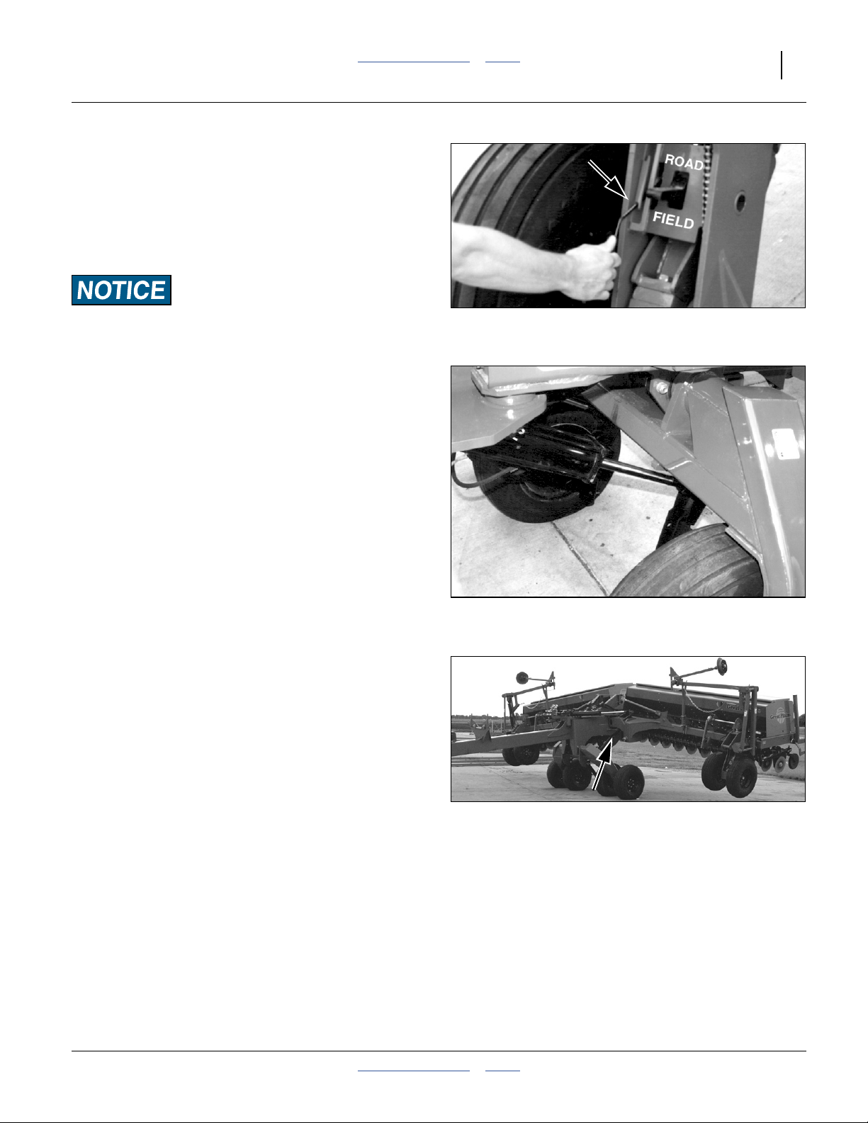
Lowering Openers
Refer to Figure 18
1. Position opener transport lock handles in FIELD
position.
2. Raise openers completely, to release locks.
3. Lower openers.
Machine Damage Risk:
Never lower openers with drill folded.
Raising Drill (Transport Lift)
Transport Lift is on a dedicated hydraulic circuit. The
center main frame raises and lowers independently of
the opener sub-frames (which are raised and lowered by
the Opener Lift circuit).
Transport Lift is normally used prior to folding and during
rate calibrations. Opener Lift, and not Transport Lift, is
used for headland turns in field operations.
Swing-up channels are used to lock the lift cylinders in
the raised (extended) configuration, preventing settling
during transport, parking, calibrations, servicing and
storage.
Refer to Figure 22
Note: Wings flex down before gauge wheels are lifted off
the ground during transport lift.
Transport Lift
1. Raise the openers. See “Raising and Lowering
Openers” on page 24.
2. If the Two Outlet conversion kit is installed, a selector
valve near the hitch must be operated to switch
between Transport Lift and Opener Lift. See “Lift
Selector Valve Operation” on page 42.
3. Supply oil to the base (extend) ends of the Transport
Lift cylinders.
Figure 20
Opener Unlock
Figure 21
Transport Lift Cylinder
Figure 22
Transport Lift
15548
15551
17349
2014-02-03 Table of Contents Index 195-069M
Page 30
26 2S-2600HD Table of Contents Index Great Plains Manufacturing, Inc.
Refer to Figure 23
4. Swing the locks up and onto the transport lift cylinders. They are temporarily held in place with polymer
bumpers. They are firmly held in place when the cylinder is relaxed in step 5.
Note: Bumpers hold the transport lift cylinder lock chan-
nels in place temporarily. The channels will remain
in position when cylinders settle against channels.
5. Slowly reverse the Transport Lift circuit lever until
both lock channels are resting firmly on the rod ends
of the transport lift cylinders. Set circuit lever to off.
Figure 23
15552
Transport Lift Cylinder Lock
Folding
Crushing Hazard:
Bystanders could be crushed between the folding drill boxes
and the drill tongue. To avoid serious injury or death, keep all
bystanders well away during folding operation.
1. Park tractor and drill on level ground with tractor
transmission in Park. Be aware of clearance needed
to fold drill.
2. Fold up markers if installed. See “Marker Opera-
tion” on page 41. Return selector valve handle to
Fold position.
Refer to Figure 24
3. Raise openers. Opener subframe must be raised for
folding. Position all six opener lock handles in ROAD
position and completely raise openers. See “Raising
and Lowering Openers” on page 24.
Note: The opener transport lock handles are spring load-
ed and can be moved to ROAD position with openers up or down, but locks only engage when
openers are completely raised. There are two locks
on each drill section.
4. Raise drill, engage lift lock channels and allow drill to
settle on lock channels. See “Raising Drill (Trans-
port Lift)” on page 25.
Note: During transport lift, wings flex down before lifting
off ground.
Machine Damage Risk:
Both Opener and Transport Lift circuits must be raised and
locked up before folding, or implement damage will result.
Figure 24 - Fold
15549
Opener Lock Up
195-069M Table of Contents Index 2014-02-03
Page 31

Great Plains Manufacturing, Inc. Table of Contents Index Operating Instructions 27
Refer to Figure 25, which depicts
1
the right latch awaiting a wing, and
2
the left latch having captured a wing.
5. Slowly supply oil to rod (retract) end of fold circuit.
1
2
Completely fold wing frames until both wing gauge
wheel pins are captured by the folding latches.
Make sure polymer bumpers in lock channels clasp the cylinder rods securely. The bumpers must hold the channels in position until cylinders settle against the channels. Inspect
bumpers regularly. Replace as needed.
6. Set Fold circuit to neutral for extra safety.
The drill is now ready for the pre-transport checklist. See
“Transport” on page 28.
Figure 25
Latch Awaiting Wings
17316
2014-02-03 Table of Contents Index 195-069M
Page 32

28 2S-2600HD Table of Contents Index Great Plains Manufacturing, Inc.
Transport
Loss of Control Hazard:
Towing the drill at high speeds or with a vehicle that is not
heavy enough could lead to loss of vehicle control. Loss of
vehicle control could lead to serious road accidents, injury
and death. To reduce the hazard:
Do not exceed 20 mph.
Do not tow a drill that, when fully loaded, weighs more than
1.5 times the weight of the towing vehicle.
In the following table, multiply the total drill weight by
2
⁄
0.67 (
) to determine minimum tractor weight.
3
Weights for Tractor Requirements
Drill Weight (Pounds / Kilograms)
Drill Model
Standard “HD” Drill 10423 lbs / 4728 kg 10404 lbs / 4719 kg 10386 lbs / 4711 kg
For “HDF” Model, add... +910 lbs / +413 kg +889 lbs / +403 kg +869 lbs / +394 kg
With Dual Markers, add... +887 lbs / +402 kg +887 lbs / +402 kg +887 lbs / +402 kg
For Full Main Box Seed Load, add... +5389 lbs / +2444 kg +5389 lbs / +2444 kg +5389 lbs / +2444 kg
Small Seeds Option +619 lbs / +281 kg +603 lbs / +273 kg +586 lbs / +266 kg
Maximum Configuration:
(HDF, Dual Markers, Seed Loaded,
Small Seeds)
2S-2600HD-5206 2S-2600HD-4275 2S-2600HD-3210
18228 lbs / 8268 kg 18172 lbs / 8243 kg 18117 lbs / 8218 kg
Marker Transportation
Refer to Figure 26
Always transport markers folded flat. Make sure second
marker section rests securely on transport carrier.
Figure 26
18857
Marker in Transport Cradle
195-069M Table of Contents Index 2014-02-03
Page 33

Great Plains Manufacturing, Inc. Table of Contents Index Operating Instructions 29
Transport Checklist
Before transporting the drill, check the following items:
❑ Transport only with a tractor of proper size. See
“Specifications and Capacities” on page 104.
❑ Safety Chain in Place (page 14) - Attach safety
chain to an anchor on tractor.
❑ Drill Securely Hitched (page 14) - Always use a
locking-style pin sized to match holes in hitch and
drawbar (minimum of 1in (2.4cm) diameter).
❑ Openers Raised and Locked (page 24) - Lock
openers up into ROAD position.
❑ Tires (page 104) - Check that all tires are properly
inflated
❑ Bystanders - Check that no one is in the way before
moving. Do not allow anyone to ride on the drill.
❑ Warning Lights - Always use tractor and drill warn-
ing lights in transport.
❑ Clearance (page 104) - Know the maximum dimen-
sions of the drill in transport position and follow a
route that provides adequate clearance from all
obstructions.
❑ Stopping Distance - Allow sufficient stopping dis-
tance and reduce speed prior to any turns or maneuvers. If the drill is transported full, allow extra
stopping distance.
❑ Road Rules -Comply with all national, regional and
local laws when transporting on public roads.
❑ Parking Stands Raised (page 44) - Rotate stands
up and pin.
❑ Walkboard Ladders Raised - (if equipped)
❑ Drill Raised and Locked (page 25) - Make sure drill
is folded properly. Secure cylinder lock channels on
transport-cylinder rods and front box lift cylinders.
Allow transport lift cylinders to settle against lock
channels.
2014-02-03 Table of Contents Index 195-069M
Page 34

30 2S-2600HD Table of Contents Index Great Plains Manufacturing, Inc.
Unfolding
Drill must be left raised (transport and opener lift) prior to
unfolding.
1. Verify that the site has clearance needed to unfold
drill.
2. If equipped with markers, set Marker/Fold valve at
hitch to Fold.
3. Verify that the Transport Lift circuit is still raised, and
transport cylinder lock channels are installed.
Refer to Figure 24
4. Verify that the opener sub-frames are still raised and
locked up (handles in ROAD position).
Refer to Figure 28
5. At fold latch, prop both latch pawls on the wing
pins, raising the latches off the pins.
6. Slowly supply oil to base end of fold circuit. Unfold
wing frames by completely extending fold cylinders.
If field operations are planned:
7. Lower drill mainframe. See “Unfolding” on page 30.
8. Lower opener subframe. See “Lowering Openers”
on page 25.
2
1
Figure 27 - Unfold
Opener Unlock
15549
2
Figure 28
Latch Ready for Unfold
1
17319
195-069M Table of Contents Index 2014-02-03
Page 35

Great Plains Manufacturing, Inc. Table of Contents Index Operating Instructions 31
Lowering Drill (Transport Lift)
Lowering from Transport Lift may be done only when the
drill is unfolded.
Transport Lift is on a dedicated hydraulic circuit. The
main frame raises and lowers independently of the
opener sub-frames (which are raised and lowered by the
Opener Lift circuit).
Transport Lower
1. Unfold drill. See “Unfolding” on page 30.
2. If the Two Outlet conversion kit is installed, confirm
that the selector valve, located near the hitch, is set
for Transport Lift operations. See “Lift Selector
Valve Operation” on page 42.
3. Slowly extended the Transport Lift circuit lever until
both Transport Lift circuit cylinders are fully
extended. Set circuit lever to off or neutral (not float).
Refer to Figure 29
4. Rotate cylinder lock channels down and forward off
transport lift cylinders.
5. Slowly reverse the lift circuit lever and begin lowering
the drill. Keep the circuit engaged until both cylinders
are completely retracted. Set circuit to off or neutral.
Figure 29
Transport Lift Cylinder Lock
18960
2014-02-03 Table of Contents Index 195-069M
Page 36

32 2S-2600HD Table of Contents Index Great Plains Manufacturing, Inc.
Opener Operation
Crushing Hazard:
You will be seriously injured or killed if you are caught
between raising openers and drill frame. Always stop tractor
engine, set park bake, and remove key before adjusting or servicing openers. Keep all bystanders well away during drill
operation.
The openers are raised and lowered on their own
hydraulic circuit. When used with an active hydraulic system, constant hydraulic down pressure is placed on
openers for even soil penetration across the drill. To
operate openers with live hydraulic power, always connect the opener-lift hoses to the circuit designated for
hydraulic-motor control.
To achieve proper opener flotation, the opener hydraulic
circuit must be powered by an active hydraulic system.
An active hydraulic system requires a tractor with
closed-center hydraulics or pressure-flow compensated
hydraulics powered by a variable displacement hydraulic
pump.
To run drill on tractors with open-center hydraulics or on
tractors with fixed-displacement hydraulic pumps, you
must install a Great Plains kit, part number 194-143A.
Contact your Great Plains dealer for ordering information.
If you are not familiar with your tractor’s hydraulics, consult your tractor dealer.
For more information on opener adjustments, see “Trou-
bleshooting” on page 75.
High Pressure Fluid Hazard:
Escaping fluid under pressure can penetrate the skin causing
serious injury. Avoid the hazard by relieving pressure before
disconnecting hydraulic lines. Use a piece of paper or cardboard, NOT BODY PARTS, to check for suspected leaks. Wear
protective gloves and safety glasses or goggles when working
with hydraulic systems. If an accident occurs, seek immediate
medical attention from a physician familiar with this type of
injury.
195-069M Table of Contents Index 2014-02-03
Page 37

Great Plains Manufacturing, Inc. Table of Contents Index Operating Instructions 33
Active Hydraulic Systems
1. Lock hydraulic lever forward during field operation for
constant hydraulic flow to openers.
John Deere tractors with Sound-Gard ® Body:
Use lever lock clip, John Deere part number R52667,
to lock lever forward. See your tractor dealer for clip
purchase and installation.
John Deere 7000 Series tractors: Rotate valve
detent selector to motor position to lock lever in forward position.
John Deere 8000 Series tractors: Set timer to continuous. Push lever forward until detent clicks.
Case-IH Magnum tractors: Lock lever forward in
detent position. You may need to turn up detent pressure to its maximum setting. Do not tie hydraulic
lever past detent position with a strap. See your tractor dealer for hydraulic-system details.
Other tractors: Lock lever forward in detent position.
You may need to turn up detent pressure to maximum or use a mechanical detent holder to hold lever
forward. See your tractor dealer for proper means of
providing constant flow to openers.
Refer to Figure 30
2. With tractor hydraulic lever locked forward and openers in field position, release lock disk and set
down pressure with adjustment knob . Watch pres-
1
2
sure gauge and dial in desired pressure on openers.
There is one pressure-control valve for inboard
openers (“CENTER”) and one for outboard openers
(“WING”). If the Point Row option is installed, the
controls are Left (“LEFT”) and Right (“RIGHT”).
Note: Rotate knob clockwise to increase pressure and
counterclockwise to decrease pressure.
Equipment Damage Risk:
Tractors with load-sensing hydraulics must use the bypass
valve to operate the 2S-2600HD. Failure to use the bypass
valve can cause major tractor damage. Before adjusting
opener down pressure, set bypass valve per “Setting the
Bypass Valve” on page 19.
Equipment Damage Risk:
During operation always raise openers before turning. Never
back up or turn sharply with openers in the ground. Doing so
will plug openers and may damage equipment.
1
2
3. Once pressure is set, set knobs with lock disks .
1
4. In some applications, pressure on inboard end of
wings (CENTER) is set slightly higher than the outboard ends (WINGS) to account for additional compaction from drill transport tires and tractor tires. The
recommended pressure range for drilling is between
1200 psi and 1800 psi, and initially 1400 psi.
Figure 30 - Active
Pressure Control Valves
26477
5. For more information on adjusting hydraulic down
pressure, see “Row Unit Down Pressure (Spring)”
on page 66.
Inconsistent Population Risk:
Do not operate at pressures so high that the gauge wheels
loose traction, or are off the ground, resulting in skips and
poor seed metering.
2014-02-03 Table of Contents Index 195-069M
Page 38

34 2S-2600HD Table of Contents Index Great Plains Manufacturing, Inc.
Priority Flow Hydraulic Systems
On some tractors with load-sensing hydraulics, the circuit
#1 is capable of taking nearly 100 percent of available
hydraulic flow. Operating the openers or markers on circuit #1 will starve the other circuit, making one function
inoperable.
To operate markers and constant opener down pressure
at the same time, connect the openers to circuit #2 and
the markers to circuit #3.
Non-Active Hydraulic System
To run drill with open-center hydraulics or fixed-displacement hydraulic pumps requires a Great Plains kit, part
number 194-143A. After installing the kit, refer to the following instructions for opener operation.
1. Lower opener frames by pushing forward on tractor
hydraulic lever. Lock lever temporarily in this position
while adjusting opener down pressure.
Refer to Figure 31
2. With tractor hydraulic lever locked forward, release
lock disk and set down pressure with adjustment
knob . Watch pressure gauge and dial in desired
pressure on openers. There is one pressure-control
valve for inboard openers (“CENTER”) and one for
outboard openers (“WING”). If the Point Row option
is installed, the controls are Left (“LEFT”) and Right
(“RIGHT”).
Note: Rotate knob clockwise to increase pressure and
counterclockwise to decrease pressure.
3. Once pressure is set, set knobs with lock disks .
4. After opener down pressure is set, return tractor
hydraulic lever to neutral. This locks-in the selected
pressure, and opener frames remain fixed in this
position.
Equipment Damage Risk:
Open-center tractors and tractors with fixed-displacement
pumps are not designed to provide a continuous supply of
pressurized oil to remote valves. Locking hydraulic lever forward on these tractors can cause overheating of hydraulic oil
and tractor damage. After setting opener down pressure,
always return hydraulic lever to neutral.
1
2
1
1
2
Figure 31 - Non-Active
Pressure Control Valves
26477
195-069M Table of Contents Index 2014-02-03
Page 39

Great Plains Manufacturing, Inc. Table of Contents Index Operating Instructions 35
Note: On some tractors with very positive remote hydrau-
lic checks, a slight increase in the reading on the
pressure gauges may occur after tractor remote lever is returned to neutral. This is caused by back
pressure on opener cylinders and should be ignored. The net operating pressure on opener cylinders is maintained at the pressure you selected
while tractor remote lever was held forward-not at
the apparently increased pressure. Reactivating
tractor lever forward will confirm this.
During operation:
• Each time openers are lowered, hold tractor remote
hydraulic lever forward for a few seconds to recharge
circuit, then return it to its neutral position. The tractor
and drill should be on level ground when returning
tractor lever to neutral.
• When approaching rough terrain where you need
active hydraulics to maintain even opener penetration,
push tractor hydraulic lever forward momentarily. As
soon as you return to level ground, return lever to neutral. Do not activate tractor hydraulic lever for more
than 20 seconds at a time, once every 2 minutes.
Always wait until tractor and drill are on level ground
before returning lever to neutral. You can bump tractor
hydraulic lever forward any time on level ground to
assure the preset pressure is correctly locked in and to
reset the system.
• Always raise openers before turning. Never back up or
turn sharply with openers in the ground. Doing so will
plug openers and may damage equipment.
2014-02-03 Table of Contents Index 195-069M
Page 40

36 2S-2600HD Table of Contents Index Great Plains Manufacturing, Inc.
Loading Main Seed Box
Seed may be loaded in the field or prior to transport.
Fully loaded with dense seed, the drill can weigh an
additional 5389 lbs (2444 kg). Include this weight when
checking tractor capability.
The drill must be hitched for seed loading. The mainframe may be raised or lowered. Lowered places the
walkboards closer to the ground, reducing effort when
manually loading bagged seed. If equipped with ladders,
swing them down.
Main Seed Box Loading
1. Check that all meter doors are positioned for the
seed size, and not set for clean-out. See “Position
Seed Cup Doors” on page 49. If loading prior to
transport, set them to position 1 (smallest seed).
2. Install or remove optional seed plugs as desired for
the row spacing planned. See “Seed Tube Plug
(Small Seeds)” on page 102.
3. If loading prior to transport, and calibration has not
yet been done, set Seed Rate Handles to 0. At 0,
and with the doors at 1, no seed can leak during
transport.
4. On HDF (fertilizer-capable) drill models:
• Check that any offset box dividers are set to the
desired compartment ratio. See “Offset Box
Divider” on page 101.
• Check that the divider flap is set as desired (sepa-
rate compartments, or all-seed). See “Fertilizer
Box Operation” on page 37.
• If seeding only from the forward (seed) compart-
ment, flip the top spill flap back to prevent seed
from entering the fertilizer compartment. See “Fer-
tilizer Box Operation” on page 37.
5. Take all necessary materials safety precautions if the
seed is treated.
6. Load seed evenly into seed boxes.
7. To reduce wear, remove main shaft drive chains for
small seed boxes.
Small Seeds Box Loading
1. If loading prior to transport, and calibration has not
yet been done, set Seed Rate Handles to 0. At 0, no
seed can leak during transport.
2. Take all necessary materials safety precautions if the
seed is treated.
3. Load seed evenly into seed boxes.
4. To reduce wear, remove main shaft drive chains for
main seed boxes.
195-069M Table of Contents Index 2014-02-03
Page 41

Great Plains Manufacturing, Inc. Table of Contents Index Operating Instructions 37
Initial Seeding Depth
Refer to Figure 32
5. Set opener seeding depth by adjusting press-wheel
height . To adjust, first raise openers slightly, then
lift and slide T handles on top of openers Adjust all
press wheels to the same height. T handles adjust at
1
handle step.
• For more shallow seeding, slide T handles forward
1
2
⁄
in (6.4mm) seeding depth change per minimum
4
F
toward implement.
F
2
B
• For deeper seeding, slide T handles backward
away from implement.
6. While seeding, remember:
• Raise openers before turning. Never back up or
turn sharply with openers in the ground. Doing so
will plug openers and may damage equipment.
• Check periodically for plugged openers and
hoses.
For information on opener adjustments, “Row Unit
Adjustments” on page 65. For information on troubleshooting opener problems, see “Troubleshooting” on
page 75.
Fertilizer Box Operation
The 2S-2600HDF models are equipped with a fertilizer
compartment capable of planting seed only, or seeding
and applying fertilizer in the same field pass.
Use only dry, granular fertilizer in the fertilizer box.
Seeding and applying fertilizer
1. Clean any seed or debris from fertilizer compartment. See “Fertilizer Box Clean-Out” on page 89.
B
1
26441
0%
Fert.
60%
Seed
Figure 32
Initial Opener Depth
40%
Fert.
Standard Divider
Configurations
100%
Seed
Refer to Figure 33
2. Adjust dividers between seed and fertilizer compartments to desired capacity.
68%
Seed
32%
Fert.
55%
Seed
45%
Fert.
The standard fertilizer dividers partition the drill
boxes into:
60 percent seed : 40 percent fertilizer, or;
100% seed (see page 40).
The optional offset dividers partition the drill boxes
into:
Offset Divider
Configurations
Figure 33
Seed Box Divider
27003
68% seed : 32% fertilizer,
55% seed : 45% fertilizer, or;
100% seed (see page 40).
2014-02-03 Table of Contents Index 195-069M
Page 42

38 2S-2600HD Table of Contents Index Great Plains Manufacturing, Inc.
Divided Capacities
Capacity Ratio Total Capacity
Divider Seed Fertilizer Seed Fertilizer
None 100% 0% 86.4 bu
3045 ltr.
Standard 60% 40% 51.8 bu
1827 ltr.
Offset
to rear
Offset
to front
Divider Removal
Refer to Figure 34 (which depicts a smaller 9ft box for clarity
- the 13ft box has four partitions)
a. Remove
3
at each end of drill box (2 locations).
b. Remove
lid-hinge brackets (3 locations).
c. Loosen but do not remove
clamp the lid assembly angle irons to the plastic
dividers .
68% 32% 57.8 bu
2070 ltr.
55% 45% 47.5 bu
1675 ltr.
5
⁄
in bolts and flange nuts from tabs
16
5
⁄
in bolts (4) and nuts (5) from
16
9
1 2
4 5
6
1
⁄
in bolts and nuts that
4
8
7
0
34.6 bu
1218 ltr.
27.6 bu
974 ltr.
38.9 bu
1370 ltr.
1
8
7
9
2
3
2
3
1
6
5
4
d. Lift lid assembly out of drill box. Lift dividers out
of drill box. Reinstall standard or offset dividers.
e. Reinstall lid assembly by reversing step d through
step a.
Refer to Figure 35
6. Check that the seed/fertilizer flap is closed so seed
and fertilizer cannot pass between compartments.
Flap flips forward to block passage. The flap top
edge is secured to the dividers. Rotate the bent clips
to engage the edge of the flap, and tighten the
knobs.
8 9
Figure 34
Box Divider Removal
Figure 35
Seed/Fertilizer Flap Closed
27050
16383
195-069M Table of Contents Index 2014-02-03
Page 43

Great Plains Manufacturing, Inc. Table of Contents Index Operating Instructions 39
Refer to Figure 36
7. Check that fertilizer clean-out door is latched
securely as shown. Close all door latches before
1
loading fertilizer compartment.
1
Refer to Figure 37
8. Open main seed box lid.
9. Raise spill flap over fertilizer compartment and swing
it forward until it rests against open drill-box lid. The
spill flap serves as a spill guard to keep fertilizer out
of the seed compartment.
10. Fill fertilizer compartment.
11. Calibrate fertilizer-application rate as explained
under “Fertilizer Rate Calibration” on page 56.
Figure 36
Cleanout Door Latch
Figure 37
Spill Flap Open to Fertilizer
16377
14875
2014-02-03 Table of Contents Index 195-069M
Page 44

40 2S-2600HD Table of Contents Index Great Plains Manufacturing, Inc.
Seeding with Both Compartments
1. Clean out boxes. See “Main Box Seed Meter
Clean-Out” on page 89 and “Fertilizer Box
Clean-Out” on page 89.
1
Refer to Figure 38
2. Open divider door between seed and fertilizer compartments. To open door, loosen knobs . Loosen
knobs until bent clips can be turned away from door
1
.
3. When all bent clips have been turned, lift vinyl dew
shield (not shown) and flip the flap backward over
fertilizer-tray openings .
Refer to Figure 39
4. With seed/fertilizer flap covering fertilizer openings, lower vinyl dew shield to hold flap over fertil-
izer openings and away from divider.
5. To avoid unnecessary wear, remove both fertilizer
Range drive chains. “Setting Fertilizer Drive
Range” on page 54.
3
2
4
1
2
1
1
Figure 38
Open Seed/Fertilizer Flap
4
2
3
16383
2
Figure 39
Flap Secured
195-069M Table of Contents Index 2014-02-03
16380
Page 45

Great Plains Manufacturing, Inc. Table of Contents Index Operating Instructions 41
Marker Operation
Optional markers are equipped with a double-selector
valve, on the tongue near the hitch, to combine the
box-fold circuit with the marker circuit. On a 2-outlet tractor, there is a second selector valve, for the lift circuits,
mounted above the marker/fold selector.
Refer to Figure 40
After drill is unfolded for field operation, move double-selector valve handle from forward fold position to
marker circuit (back ). Before operating markers, make
sure they are properly bled as described in “Bleeding
Hydraulics” on page 79.
2
1
2
1
Single Marker Operations
To operate a single marker, activate tractor remote
hydraulic lever to move marker in desired direction.
Single markers are equipped with a needle valve to control marker folding speed. Excessive folding speed can
damage markers, so adjust needle valve to a safe operating speed as described under “Marker Speed” on
page 73.
Figure 40
Fold / Marker Selector
15550
Dual Marker Operations
Dual markers are equipped with an automatic sequence
valve to control lift sequence. Starting with both markers
up, the sequence is:
• Activate hydraulic lever; right marker lowers while left
marker stays up.
• Reverse hydraulic lever; right marker raises while left
marker stays up.
• Activate hydraulic lever; left marker lowers while right
marker stays up.
• Reverse hydraulic lever; left marker raises while right
marker stays up.
Pattern repeats.
Folding speed of dual markers is adjusted with adjustment screws on sequence-valve body. Excessive folding
speed can damage markers, so adjust markers to a safe
folding speed as described under “Marker Adjust-
ments” on page 70.
2014-02-03 Table of Contents Index 195-069M
Page 46

42 2S-2600HD Table of Contents Index Great Plains Manufacturing, Inc.
Lift Selector Valve Operation
Tractors with only two remote circuits need an optional
selector valve, which shares a single tractor circuit
between transport lift and opener lift. Two Outlet Tractor
Hydraulic Kit Great Plains Part number 194-122A. This
combines the transport lift hydraulic circuit and opener lift
hydraulic circuit.
If no markers are installed, the lift selector valve is
mounted on the standard tongue valve plate near the
hitch. If markers are also installed, the lift selector valve
mounts above the marker valve on an extension plate.
Refer to Figure 41, which depicts the optional lift selector
valve on a drill without markers.
To operate, move handle from forward transport lift posi-
1 2
tion to rear opener lift position .
Note: Do not rely on this valve to lock up either transport
lift circuit or opener subframe circuit. Use the lift
locks.
1
Figure 41
Optional Lift Selector
2
15550
Point Row Operation
Refer to Figure 41
The optional point-row controller allows you to raise and
lower openers on one drill section independently of the
other. A POINT ROW CONTROL module in the tractor
cab operates solenoid valves on the drill, which raise and
lower opener sub-frames independently (or together).
The mechanical clutches on each section suspend seeding when raised.
To raise and lower openers on all sections together, set
POWER switch ON-left, so MASTER LIFT CONTROL
indicator is illuminated. Raise or lower with the ALL
UP / ALL DOWN switch under the indicator.
To raise and lower opener sections independently, set
POWER switch ON-right so SECTION CONTROL
indicator is illuminated. Raise and lower openers on
each section by operating the UP / DOWN switches
illuminated under the SECTION CONTROL.
Note: At the pressure control valves, the “CENTER” and
“WING” decals are replaced by “LEFT” and
“RIGHT” decals, respectively. The controller’s
CENTER control circuit is not used on 2S-2600HD.
Note: Turn Point Row POWER switch to OFF-center
when tractor is off.
1
2
3
1
4
5
1
2
3
4
1
5
Figure 42
Point Row Controller
17060
195-069M Table of Contents Index 2014-02-03
Page 47

Great Plains Manufacturing, Inc. Table of Contents Index Operating Instructions 43
Shaft Monitor Operation
The optional shaft monitor generates an alarm if either of
the two main seed box meter shafts on the drill stop turn-
ing for more than 20 seconds.
Refer to Figure 43
To operate shaft monitor, turn system on by activating
on-off switch on monitor head. If seed-cup shafts are
turning, both indicator lights are illuminated and no
alarm sounds.
If any seed-cup shaft stops for 20 seconds, an alarm
sounds and the indicator for that section flashes on the
monitor, designating the failed shaft.
Note: The 20-second delay is to prevent nuisance alarms
when turning at the end of the field.
Note: If a failure does occur and an alarm sounds, re-
member you have traveled for 20 seconds without
planting with that drill section. If due to wheel lift or
low tire pressure, you may have been planting at
progressively lower populations before that.
1
a
2
2
1
Figure 43
Shaft Monitor Head
27049
Electronic Acremeter
Refer to Figure 44
A battery-operated electronic acre counter is supplied
with the drill. The display module for the system is
normally on the front face of the main toolbar near the
left gauge wheel and close to the sensor. (For 2S-2600
models the meter is mounted on the right hand box
frame.)
If your drill was originally equipped with this acremeter, it
will have been supplied already programmed.
The acremeter calculates and displays the field acres
and total acres accumulated.
The meter counts rotations of the main ground drive
shaft before the clutch. It tallies all movements with the
drill unfolded, whether planting or not.
The counter operates in one of two modes, in sleep
mode or in entry mode. (See separate manual
194-074M specifically for operations of this meter).
For previous style acremeter used with this drill see
“Appendix B - Previous Style Acremeter” on page
112.
Figure 44
Electronic Acremeter
34776
a. The older Vansco shaft monitor was 30 seconds.
2014-02-03 Table of Contents Index 195-069M
Page 48

44 2S-2600HD Table of Contents Index Great Plains Manufacturing, Inc.
Parking
Following these steps when parking for less than 36
hours. For longer periods, see Storage, the next topic.
Parking with Drill Unfolded
This drill has a negative tongue weight when unfolded and
openers are raised. Lower parking stand, lower openers and
remove hydraulic down pressure before unhitching the drill in
the unfolded position. Unhitching in the unfolded position with
the openers raised could result in sudden elevation of the
tongue, causing injury or death.
1. Remove jack from storage location on top of tongue
and pin it on post on left side of tongue as shown on
page 15. Extend jack until weight of tongue is on
jack. Leave tractor hitched for the moment.
Refer to Figure 45 and Figure 46
2. Lower parking stands located on outer ends of drill
by unpinning keeper pin and rotating stands down.
Place a block under foot of stand if it does not contact the ground.
3. Lower openers and reduce hydraulic down pressure
to zero.
4. Unplug drill hydraulic hoses and electrical lines from
tractor.
Figure 45
Wing Stand Pinned Up
18837
Use caution when removing the hitch pin. Slight tongue elevation may occur, even with openers and parking stands lowered.
5. Remove hitch pin first, then safety chain from tractor
drawbar.
Note: After unhitching the unfolded drill, the tongue may
rise above tractor-drawbar height. Lower tongue by
connecting the opener-lift circuit and pressurizing
openers.
Parking with Drill Folded
1. Raise, lock and fold drill into transport position.
2. Park drill on a level, solid area.
3. Remove tongue jack from its storage location on top
of tongue and pin it on post on left side of tongue as
shown on page 15. Extend jack until weight of
tongue is on jack. If ground is soft, place a board or
plate under jack to widen ground-contact area.
4. Unplug hydraulic hoses and electrical lines from tractor.
5. Remove hitch pin first, then safety chain from tractor
drawbar.
195-069M Table of Contents Index 2014-02-03
Wing Stand Pinned Down
Figure 46
18837
Page 49

Great Plains Manufacturing, Inc. Table of Contents Index Operating Instructions 45
Storage
Store the drill where children do not play. If possible,
store it inside for longer life.
1. Perform the drill Parking checklist.
2. Lubricate the drill at all points listed under “Lubrica-
tion” on page 91.
3. Check all bolts, pins, fittings and hoses. Tighten,
repair or replace parts as needed.
4. Check all moving parts for wear or damage. Make
notes of any parts needing repair before the next
season.
5. Raise and lock up openers.
Raise and lock up Transport lift.
Fold drill.
Do not lower openers with drill folded.
6. Plug or cap seed delivery and fertilizer tubes to prevent pest entry.
7. Use touch-up paint to cover scratches, chips and
worn areas to prevent rust.
2014-02-03 Table of Contents Index 195-069M
Page 50

46 2S-2600HD Table of Contents Index Great Plains Manufacturing, Inc.
Adjustments
To get full performance from your drill, you need an
understanding of all component operations, and many
provide adjustments for optimal field results.
The 2S-2600HD has double-disk openers with
depth-controlling press wheels mounted on floating
opener frames. Opener bodies are staggered for easy
soil flow. All openers pivot on a common axis to maintain
consistent depth as the opener frames follow contours. A
spring provides the down pressure necessary for opener
double disks to open a seed furrow. The spring allows
openers to float down into depressions and up over
obstructions. Individual openers can be adjusted to
account for tire tracks.
Even if your planting conditions rarely change, some of
these adjustment items need periodic attention due to
normal wear.
Seed and Fertilizer Rate
Materials are applied by fluted feed meters driven by the
gauge wheels. Independent mechanisms control seed
and fertilizer application. Optional Small Seeds rate is
controlled entirely by Rate Handles.
Adjustment Page The Adjustment Affects
Main Box Seed rate is controlled by adjustments for:
• Drive Type sprocket (one sprocket each gauge wheel)
• Seed Rate Handle (one handle each seed box)
• Feed Cup Door (one each seed tube)
Fertilizer rate is controlled by:
• Range sprockets (one set each fertilizer box)
• Final Driver/Driven sprockets (one set each box)
Planting Depth
Setting nominal planting depth, and achieving it consistently, is affected by multiple adjustable drill functions,
from greatest to least effect they are:
• Opener Depth (Press Wheel Height)
• Opener Frame Down-Force,
• Row Unit Down Pressure (Spring),
• Opener Height,
• Opener-Subframe Adjustment,
• Frame Weight (at higher pressures), and;
• Disk Blade Adjustments (as blades wear).
Setting Main Box Seed Rate 47
Setting Drive Type 48 Coarse control of seeding rate
Main Box Seed Rate Handle 49 Fine control of seeding rate
Position Seed Cup Doors 49 Consistent seed delivery for certain seed sizes
Setting Fertilizer Rate 53
Setting Fertilizer Drive Range 54 Coarse control of application rate
Setting Fertilizer Final Drive 55 Fine control of application rate
Frame Level 60 Section-to-section planting consistency
Small Seeds Rate 58 Small seeds population
Opener Frame Down-Force 62 Consistent seeding depth
Opener-Subframe Adjustment 64 Level row unit running in desired pressure range
Frame Weight 61 Achieving higher down-force settings
Row Unit Adjustments 65
Opener Height 66 Seeding depth in tire tracks
Row Unit Down Pressure (Spring) 66 Level row units and consistent seeding depth in tire tracks
Disk Blade Adjustments 67 Consistent seeding depth
Seed Firmer Adjustments 68 Consistent seed placement and coverage
Opener Depth (Press Wheel Height) 69 Seeding depth
Marker Adjustments 70 Correctly offset and visible pass marks
195-069M Table of Contents Index 2014-02-03
Page 51

Great Plains Manufacturing, Inc. Table of Contents Index Adjustments 47
Setting Main Box Seed Rate
Accurately obtaining the desired seed population
requires four steps:
1. Setting Drive Type sprockets (from chart)
2. Setting initial Seed Rate Handle (from chart)
3. Positioning Seed Cup Door (by seed type)
4. Calibration: checking actual seeding rate
Seed rate charts are found in a separate Seed Rate
Manual (which is normally stored in a weatherproof
holder on the drill, for field reference). The charts list
proper sprocket pairings and seed-rate-handle settings
for various seeds and seeding rates.
The seed-rate charts are based on cleaned, untreated
seed of average size and test weight. The charts are
based on 9.5Lx15 6-ply Rib Implement gauge wheel tires
and 11Lx15 12-ply Rib Implement transport tires, inflated
to factory specification. Many factors will affect seeding
rates including foreign material, seed treatment, seed
size, seed weight, field conditions, tire pressure and test
weight. Minor adjustments are commonly required. Set
and check the seeding rate using the procedures below,
then readjust the rate as necessary.
°
2014-02-03 Table of Contents Index 195-069M
Page 52

48 2S-2600HD Table of Contents Index Great Plains Manufacturing, Inc.
Setting Drive Type
Refer to Figure 47
Drive Type is determined by the size (tooth count) of a
sprocket on the seed jackshaft of each drill section. If
1
changed, the sprocket must be set identically on each
drill section (2 locations).
For correct Drive Type, refer to the charts in the Seed
Rate manual. The charts list Drive Types as 1, 2, 3 or 4.
Each Drive Type corresponds to a specific sized
sprocket, per the table at right, and Figure 48 below.
Changing Drive Type
1. Loosen top idler and slide idler well forward, par-
2
ticularly if changing to Drive Type 1.
2. Lift drive chain off sprocket currently in use.
3. Remove lynch pin and rearrange sprockets on
jackshaft . Sprocket corresponding to the required
3
4 5
1
Drive Type is second innermost. Make sure all 4
sprockets are accounted for when remounting them
on the shaft.
4. Remount drive chain on the second innermost (Drive
Type) sprocket.
5. Re-engage top idler and secure. Allow
1
⁄
in (1.3cm)
2
slack in longest (top) span of chain.
6. Set the same Drive Type on both drill sections.
5
3
2
4
Figure 47
Drive Type 2 Configured
Drive
Type
Sprocket Relative Speed
1 72 Tooth Slowest
2 34 Tooth 2.12 times faster than Type 1
3 23 Tooth 3.13 times faster than Type 1
4 14 Tooth 5.14 times faster than Type 1
1
26481
Figure 48
15606
Drive Type Chain Routing
195-069M Table of Contents Index 2014-02-03
Page 53

Great Plains Manufacturing, Inc. Table of Contents Index Adjustments 49
Main Box Seed Rate Handle
There are main box seed rate handles for each section of
the drill (2 handles total). Generally, all need to be set
identically, and you need to calibrate only one section.
The seed rate handle controls the percent engagement
of the seed sprocket in each seed cup. The initial setting
of the handle is given by the Seed Rate Chart.
Note: You can temporarily stop seed flow to a drill section
by setting a handle to zero.
To set a handle:
2
1. Loosen wing nut under handle.
2. Move indicator from current setting to about 10
past the new desired value from calibration or the
Seed Rate Chart, then move it back to the new
desired value.
3. Tighten wing nut.
1
2
Position Seed Cup Doors
Refer to Figure 50,
which depicts the seed cup door handle in position .
At each main seed box seed tube, adjust the seed cup
door handle for the seed size.
The handle has three normal operating position detents:
(top detent) is for the smallest seeds.
1
Use it for wheat and similar small seeds.
(middle detent) is for larger seeds.
2
Use it for soybeans and similar larger seeds.
(bottom detent) is for oversize or fragile seeds.
3
If you experience excessive cracking with
setting , use setting .
Note: Handle position is used for cleanout, not plant-
4
2 3
5
ing. If set to this position with seed loaded, it may be
difficult to reset it to a normal operating position.
3
1
Figure 49
Seed Rate Handle
4
1
2
3
Figure 50
Seed Cup Door Handle
17618
5
26211
2014-02-03 Table of Contents Index 195-069M
Page 54

50 2S-2600HD Table of Contents Index Great Plains Manufacturing, Inc.
Main Box Seed Rate Calibration
Differences will exist between the tested seed and field
conditions used to generate the Seed Rate Charts, and
your seed and conditions. To accurately achieve your target population, Great Plains recommends calibrating.
Perform the calibration with the drill raised for transport,
but with the opener frames lowered (if the openers are
raised, the clutches disengage). Leave the tractor
hitched for movement control. Block the tires not being
used in the calibration.
Crushing Hazard:
You may be severely injured or killed by being crushed from a
falling implement or openers. Always have transport locks in
place and frame sufficiently blocked up when working on the
drill.
1. Rotate the gauge wheels and check that the drives
and seed cups are engaged, working properly and
free from foreign material. If not already done, set
the Drive Type, Seed Rate Handle and Seed Cup
Doors across the drill. If fertilizer is loaded, remove
the fertilizer drive chain (unless you are simultaneously calibrating fertilizer rate).
2. Note the current reading of the acremeter, unless
you do not plan to rely on it for the calibration.
3. Check that your gauge-wheel tires are 9.5Lx15 6-ply
Rib Implement and properly inflated. See “Tire Infla-
tion Chart” on page 104.
4. Record the weight of one to three empty containers
collectively large enough to hold seed metered for
6% of one acre.
5. Place several pounds of seed over three seed cups
on the outside end of the left drill box. Pull lower end
seed hoses off of these drops at the opener end.
6. Turn gauge wheel several times to fill seed cups.
Turn until seed drops to ground from each hose.
7. Place empty container(s) under the three hoses to
gather metered seed.
8. Turn gauge wheel until one acre is tallied on acremeter (203 wheel rotations). While turning, check that
cups have ample seed coming into them.
For example:
on a drill with a row spacing of:
7.5in
and row count of:
42
you desire to plant barley at:
49 pounds per acre
which, from the chart, is an initial Seed Rate Handle
scale setting of:
40
For example:
three empty 1.8 pound containers weigh:
5.4 lbs
Gauge wheel rotations for one acre:
203
9. Weigh metered seed. Subtract initial weight of container(s)
NetWeight GrossWeight ContainerWeights–=
For example: the containers weighed a total of 8.0
pounds after test:
2.6 lbs net
2.6 8.0 5.4–=
195-069M Table of Contents Index 2014-02-03
Page 55

Great Plains Manufacturing, Inc. Table of Contents Index Adjustments 51
10. Divide the net seed weight by three. Multiply by number of openers on your drill to determine the total of
pounds-per-acre seeded.
11. The Seed Rate Handle scale is a percentage of
meter opening, and is quite linear near scale center.
Calculate a new scale setting based on the test.
Set the Seed Rate Handle to the new scale setting.
12. You may want to repeat calibration procedure at the
new setting if your results varied greatly from the
Seed Rate Chart, or if you must operate near the
ends of the Seed Rate handle scale (0-20 or
90-100).
13. Set the right drill section to match the now-calibrated
left section.
14. With calibration complete, Reinstall fertilizer chain (if
removed), reconnect seed hoses, and lower gauge
wheel to ground.
When drilling, check seeding rate by noting acres drilled,
amount of seed added to drill and seed level in drill box.
If you are seeding more or less than desired, adjust rate
slightly to compensate for field conditions.
NetWeight
MeasuredRate
-----------------------3
OpenerCount×=
For example:
on the 42-row 7.5in drill:
36.4 lbs/ac
2.6
------
36.4
NewScale
42×=
3
TargetRate
------------------------------- MeasuredRate
OldScale×=
For example:
the target rate was 49 lbs/ac, and the initial scale 40:
the new scale setting is:
54
49
-------- -
53.8
36.4
40×=
2014-02-03 Table of Contents Index 195-069M
Page 56

52 2S-2600HD Table of Contents Index Great Plains Manufacturing, Inc.
Reading a Seed Rate Chart
1. Find your seed. Charts are in alphabetical order by
seed name. Charts covering more than one seed
may be out of order.
For Rape, see Alfalfa.
For Sudan, see Flax.
This example presumes you desire to plant Barley at
48 pounds per acre with a 7.5in drill.
There are multiple charts for some seeds, and the
rates may overlap. Use the chart where your desired
rate is closest to 50 on the Seed Rate Handle scale.
In our example, that would be Barley chart 2 of 3.
If your seed is not listed, find one with similar size,
shape and density. Density of the test seed used to
develop the chart appears under the right end of the
handle scale values.
2. Note the Drive Type in the upper left corner of the
chart for your seed. This number (1-4) is used to
determine the seed jackshaft sprocket. See page 48.
In the example, this is Drive Type 2 (34T sprocket).
3. Find your row spacing in the far left column.
4. Locate your desired seed rate in the table row for
your row spacing.
In the example, 49 is the closest to 48.
5. Note the Seed Rate Handle setting required, at the
top of the column at that seed rate. This is the initial
value set on the Seed Rate Handle. See page 49.
In the example, start with a handle setting of 40, and
calibrate. When a target rate falls halfway between
handle settings, you can adjust the handle slightly to
compensate, but calibration is apt to result in further
adjustment anyway.
195-069M Table of Contents Index 2014-02-03
Page 57

Great Plains Manufacturing, Inc. Table of Contents Index Adjustments 53
Setting Fertilizer Rate
The 2S-2600HDF fertilizer meters are driven from the
clutch shaft through a series of sprockets. This system is
independent of the seed meter drive, and is unaffected
by Drive Type. Fertilizer rate is adjusted by changing 1 to
3 sprockets on each drill section (2 sets total).
Fertilizer application rates vary with fertilizer type, density and particle size. Relative humidity and field conditions can also affect application rates. The chart in the
Seed Rate Manual is based on fertilizer with average
particle size and a density of 65 pounds per cubic foot.
Initially set rate according to charts, then calibrate the
drill to your material as described on this page.
Perform initial setup and calibration for the left drill box.
Once final are determined, set the right box to match.
Accurately obtaining the desired application rate requires
four steps:
1. Adjusting target rate for large differences between
material and chart density.
2. Setting Range sprocket (from chart)
3. Setting initial Driver / Driven sprockets (from chart)
4. Calibration: checking actual application rate
°
Adjusting for Density
The fertilizer meter rate chart is based on fertilizer with a
density of 65 pounds per cubic foot (1.04 kg/liter). If your
fertilizer density is within a few percent of that, you can
skip this step and rely on calibration to determine final
Driver/Driven setup.
For larger variances, particularly with very low densities,
pre-compensating can simplify calibration, by choosing a
different target chart value for the application rate.
1. Find your actual material density. Normally, this
reported on the container in which it was supplied. If
not, weigh a known volume and calculate it.
2. Find your material Density in the table at right, and
the Conversion Factor below it.
3. Adjust your target application rate prior to consulting
the Fertilizer Rate Chart.
4. Consult the Fertilizer Rate Chart for the Adjusted
rate.
5. Calibrate using the sprocket setup for the adjusted
rate.
Density: lbs/cu-ft
(kg/liter)
Conversion Factor 1.45 1.30 1.20 1.10
Density: lbs/cu-ft
(kg/liter)
Conversion Factor 1.00 0.93 0.87 0.81
AdjustedRate TargetRate ConversionFactor×=
Example: Your fertilizer has a density of 45 pounds per
cubic foot, and you want to apply 100 pounds per acre
with your 7.5in drill.
145 100 1.45×=
Example: the adjusted 145 rate corresponds to a High
Range, and 17T/19T Driver/Driven final drive.
45.0
(0.72)
65.0
(1.04)
50.0
(0.80)
70.0
(1.12)
55.0
(0.88)
75.0
(1.20)
60.0
(0.96)
80.0
(1.28)
2014-02-03 Table of Contents Index 195-069M
Page 58

54 2S-2600HD Table of Contents Index Great Plains Manufacturing, Inc.
Setting Fertilizer Drive Range
Refer to the Fertilizer Rate Chart in the Seed Rate Manual to find the correct Range sprocket size for your drill’s
row spacing and target (or adjusted) application rate.
Setting High Range
Refer to Figure 51 (gray arrow shows chain direction)
High Range uses the smaller 16T sprocket .
2
4
5
1
2
1. Loosen the idler sprocket and remove chain from
driving and range sprockets.
5 1
3
2. Open chain at removable link. Remove and save the
16-pitch section of the chain.
3. Loosen the set screws on the driving sprocket ,
4 5
and slide it on the shaft until it is in alignment with the
small 16T High Range sprocket .
1
Refer to Figure 52
4. Re-assemble and re-mount the chain. Make sure the
open ends of all chain clips face away from the direction of chain travel (shown by the gray arrow).
5. Re-engage the idler sprocket , allowing
3
1
⁄
in
4
(6.4mm) slack in the top chain span. Tighten set
screws on driving sprocket .
4 5
6. If this is the final Range setting, after calibration,
repeat step 1 through step 5 for the right drill section.
Setting Low Range
Refer to Figure 51
Low Range uses the larger 44T sprocket . If it is
1
already engaged by the chain, no change is necessary.
1. Loosen the idler sprocket and remove chain from
driving and range sprockets.
5 1
3
2. Reinsert the saved 16-pitch section of the chain.
This section has clips on each end.
3
Figure 51
Fertilizer Drive Low Range
21778
3. Loosen the set screws on the driving sprocket ,
4 5
and slide it on the shaft until it is in alignment with the
large 44T Low Range sprocket .
1
4. Re-assemble and re-mount the chain. Make sure the
open ends of chain clips face away from the direction
of chain travel (shown by the gray arrow).
5. Re-engage the idler sprocket , allowing
3
(6.4mm) slack in the top chain span. Tighten set
screws on driving sprocket .
4 5
1
⁄
in
4
Figure 52
26482
Chain Clip Orientation
6. If this is the final Range setting, after calibration,
repeat step 1 through step 5 for the right drill section.
195-069M Table of Contents Index 2014-02-03
Page 59

Great Plains Manufacturing, Inc. Table of Contents Index Adjustments 55
Setting Fertilizer Final Drive
Refer to the Fertilizer Rate Chart on in the Seed Rate
Manual to find the correct Final Drive sprocket sizes for
your drill’s row spacing and target (or adjusted) application rate.
Refer to Figure 53
To change the Final Drive setting:
DRIVER
1
DRIVEN
1. Loosen idlers and slide idler sprockets out of
1
engagement with chain.
2. Remove linch pins from both sprocket shafts, and
2
remove sprockets.
3. Place correct Driver and Driven sprockets on their
respective shafts.
4. Store sprockets not used on ends of shafts.
Re-install pins.
5. Reinstall chain and engage idlers, allowing
1
⁄
in
4
(6.4mm) slack in the top chain span.
6. If this is the final setting, after calibration, repeat step
1 through step 5 for the right drill section.
2
Figure 53
Fertilizer Final Drive
2
16378
2014-02-03 Table of Contents Index 195-069M
Page 60

56 2S-2600HD Table of Contents Index Great Plains Manufacturing, Inc.
Fertilizer Rate Calibration
Differences will exist between the tested fertilizer and
field conditions used to generate the Rate Chart, and
your fertilizer and conditions. To accurately achieve your
target application, Great Plains recommends calibrating.
Perform the calibration with the drill raised for transport,
but with the opener frames lowered (if the openers are
raised, the clutches will disengage). Leave the tractor
hitched for movement control. Block the tires not being
used in the calibration.
1. Rotate the gauge wheels and check that the drives
and seed cups are engaged, working properly and
free from foreign material. If not already done, set
the Range and Final Drive for the left section. If seed
is loaded, remove a seed drive chain or set the Seed
Rate Handle to 0 (unless you are simultaneously calibrating seed and fertilizer rates).
2. Note the initial reading on the acremeter, unless you
do not plan to rely on it for the calibration.
3. Check that your gauge-wheel tires are 9.5Lx15 6-ply
Rib Implement and properly inflated. See “Tire Infla-
tion Chart” on page 104.
4. Record the weight of one to three empty containers
collectively large enough to hold fertilizer metered for
6% of one acre.
5. Place several pounds of fertilizer over three fertilizer
openings the outside end of the left drill box. Pull
lower end fertilizer hoses off of these drops at the
opener end.
6. Turn gauge wheel several times to fill flute cups. Turn
until fertilizer drops to ground from each hose.
7. Place empty container(s) under the three hoses to
gather metered fertilizer.
8. Turn gauge wheel until one acre is tallied on acremeter (203 wheel rotations). While turning, check that
cups have ample fertilizer coming into them.
9. Weigh metered fertilizer. Subtract initial weight of
container(s).
Crushing Hazard:
You may be severely injured or killed by being crushed from a
falling implement or openers. Always have transport locks in
place and frame sufficiently blocked up when working on the
drill.
For example:
you desire to apply 65 lb/cu-ft material at a rate of:
78 pounds per acre
on a 7.5in row spacing drill with a row count of:
42
Per the table, the drive system setup is:
Low Range
21T Driver
16T Driven
Gauge wheel revolutions per acre:
203
For example:
three empty 1.8 pound containers weigh: 5.4 lbs
Possible Chemical Hazard: Follow material supplier recommendations for safety precautions in handling fertilizer.
NetWeight GrossWeight ContainerWeights–=
For example:
the three containers weighed a total of 11.3 pounds after
test: 5.9 lbs net
5.9 11.3 5.4–=
195-069M Table of Contents Index 2014-02-03
Page 61

Great Plains Manufacturing, Inc. Table of Contents Index Adjustments 57
10. Divide the net fertilizer weight by three. Multiply by
number of openers on your drill to determine the
total of pounds-per-acre applied.
11. Subtract to calculate the difference between the
measured rate and the original target rate.
12. If a Density Adjustment was made (see page 53),
apply it to the variance.
13. Consult the chart for the chart rate used for your first
calibration run with this material. If the just-measured
result was low, add the [adjusted] variance to the
previously used chart rate. If the measured result
was high, subtract the [adjusted] variance from the
previous chart rate.
14. Reset the fertilizer Range and Final Drive based on
the settings at the new chart rate.
NetWeight
MeasuredRate
-----------------------3
RowCount×=
For example:
a 42-row (7.5in) drill: 82.6 lbs/ac
5.9
------
82.6
Variance TargetRate MeasuredRate–=
42×=
3
For example:
the target rate was 78 lbs/ac:
new variance=5
4.6 82.6 78–=
AdjustedVariance Variance CorrectionFactor×=
In the example, we are using 65# material, so no correction factor is applied.
For example:
Our measured rate was high, so we
subtract the variance (5)
from the chart rate (78)
to obtain a new chart rate (73).
This corresponds to a new drive setup of:
Low Range
21T Driving
18T Driven
15. You may want to repeat calibration procedure if your
results varied greatly from the desired target rate.
16. With calibration complete, Reinstall seed chain (if
removed) or reset Seed Rate Handle, reconnect
hoses, and lower gauge wheel to ground.
17. Set the right drill section to match the now-calibrated
left section.
When drilling, check fertilizer rate by noting acres drilled,
amount of material added to drill and material level in drill
box. If you are applying more or less than desired, adjust
rate slightly to compensate for field conditions.
When drilling, check metering rate by noting acres
drilled, amount of fertilizer added to drill and level of
material in drill box. If you are applying more or less fertilizer than desired, adjust metering rate slightly to compensate for field conditions.
2014-02-03 Table of Contents Index 195-069M
Page 62

58 2S-2600HD Table of Contents Index Great Plains Manufacturing, Inc.
Small Seeds Rate
Seeding rate from the optional Small Seeds Attachment
is controlled entirely by seed rate handles on each small
seeds box. No sprocket changes are required, and small
seeds rate is unaffected by settings for main seed box.
Refer to Figure 54
To set Small Seeds rate, loosen the wing nut at each
handle, and adjust the lever position. Tighten nut.
Set the initial rate based on the chart in the Seed Rate
Manual.
2
Small Seeds Rate Calibration
Differences will exist between the tested seed and field
conditions used to generate the Small Seeds Rate
Charts, and your seed and conditions. To accurately
achieve your target population, Great Plains recommends calibrating.
Perform the calibration with the drill raised for transport,
but with the opener frames lowered (if the openers are
raised, the clutches will disengage). Leave the tractor
hitched for movement control. Block the tires not being
used in the calibration.
1
2
1
Figure 54
Small Seeds Rate Handle
Crushing Hazard:
You may be severely injured or killed by being crushed from a
falling implement or openers. Always have transport locks in
place and frame sufficiently blocked up when working on the
drill.
18511
1. Rotate the gauge wheels and check that the drives
and seed cups are engaged, working properly and
free from foreign material. If not already done, set
the Small Seeds Rate Handle. If fertilizer is loaded,
remove the fertilizer drive chain (unless you are
simultaneously calibrating fertilizer rate).
2. Note the initial reading on the acremeter, unless you
do not plan to rely on it for the calibration.
3. Check that your gauge-wheel tires are 9.5Lx15 6-ply
Rib Implement and properly inflated. See “Tire Infla-
tion Chart” on page 104.
4. Record the weight of one to three empty containers
collectively large enough to hold seed metered for
6% of one acre.
5. Place several pounds of seed over three seed cups
on the outside end of the left drill box. Pull lower end
seed hoses off of these drops at the opener end.
6. Turn gauge wheel several times to fill seed cups.
Turn until seed drops to ground from each hose.
7. Place empty container(s) under the three hoses to
gather metered seed.
8. Turn gauge wheel until one acre is tallied on acremeter (203 wheel rotations). While turning, check that
cups have ample seed coming into them.
For example:
using a row spacing of:
7.5in
row count:
42
you desire to plant alfalfa at:
10 pounds per acre;
this corresponds to an initial Seed Rate Handle of:
50
For example:
three 0.5 pound (8 oz) containers weigh:
1.5 lbs
Gauge wheel revolutions per acre:
203
195-069M Table of Contents Index 2014-02-03
Page 63

Great Plains Manufacturing, Inc. Table of Contents Index Adjustments 59
9. Weigh metered seed. Subtract initial weight of container(s).
10. Divide the net seed weight by three. Multiply by number of openers on your drill to determine the total of
pounds-per-acre seeded.
11. The Seed Rate Handle scale is a percentage of
meter opening, and is quite linear near scale center.
Calculate a new scale setting based on the test.
NetWeight GrossWeight ContainerWeights–=
For example:
the three containers weighed a total 2.3 lbs after test:
0.8 lbs net
0.8 2.3 1.5–=
NetWeight
MeasuredRate
-----------------------3
RowCount×=
For example:
a 7.5in drill has 42 rows:
11.2 lbs/ac
0.8
------
11.2
NewScale
42×=
3
TargetRate
------------------------------- MeasuredRate
OldScale×=
For example:
new scale:
45
10
-------- -
44.6
11.2
50×=
Note: You may want to repeat calibration procedure if
your results varied greatly from the Seed Rate
Chart, or if you must operate near the ends of the
Seed Rate handle scale (0-20 or 90-100).
12. Set the right drill section to match the now-calibrated
left section.
13. With calibration complete, Reinstall fertilizer chain (if
removed), reconnect seed hoses, and lower gauge
wheel to ground.
When drilling, check seeding rate by noting acres drilled,
amount of seed added to drill and seed level in drill box.
If you are seeding more or less than desired, adjust rate
slightly to compensate for field conditions.
2014-02-03 Table of Contents Index 195-069M
Page 64

60 2S-2600HD Table of Contents Index Great Plains Manufacturing, Inc.
Frame Level
Refer to Figure 55
The 00HD Series openers are designed to produce optimal results when the opener frames are level with the
ground. Operating with drill frame level is also recommended, and this is set by hitch height (page 15).
If planting depth is not as desired on just one or two drill
sections, first check the setup items for “Leveling the
Drill” on page 84. Then check and adjust the following
items:
• opener sub-frame adjustment: all gauge wheel trunnions in same frame pivot holes - see “Opener-Sub-
frame Adjustment” on page 64,
• opener pivot height: all openers pivoting in same hole
at their mounts (possibly excepting rows in tire tracks)
- see page 66,
• opener press wheel height: all row units set the same see page 69, and;
• opener spring down-force: all row units set the same
(possibly excepting rows in tire tracks) - see page 66.
Figure 55
Frame & Openers Level
29131
Refer to Figure 56
This photograph illustrates openers too high in front.
Increase hydraulic pressure and/or lengthen opener
springs.
Check sub-frame pivot in use at higher pressures.
Refer to Figure 57
This photograph illustrates openers too low in front, also
known as “bulldozing”. Decrease hydraulic pressure
and/or shorten opener springs.
Check sub-frame pivot if pressures have recently been
reduced.
Figure 56
Openers Too High in Front
Figure 57
Openers Too Low in Front
29132
29133
195-069M Table of Contents Index 2014-02-03
Page 65

Great Plains Manufacturing, Inc. Table of Contents Index Adjustments 61
Frame Weight
The standard 2S-2600HD includes 1587 pounds (720kg)
of weight bars inside the main tool bar. This, plus the
extra weight of 00HD row units, permits adjustment of
the full range row unit down forces. If markers are
installed, additional force is available.
Although suitcase weight brackets are available for earlier model 2S-2600 (non-HD) drills, these weight kits are
not recommended for 2S-2600HD drills.
Figure 58
Standard Frame Weights
26014
2014-02-03 Table of Contents Index 195-069M
Page 66

62 2S-2600HD Table of Contents Index Great Plains Manufacturing, Inc.
Opener Frame Down-Force
Crushing Hazard: You will be seriously injured or killed if you
are caught between raising openers and drill frame. Always
stop tractor engine, set park bake, and remove key before
adjusting or servicing openers. Keep all bystanders well away
during drill operation.
High Pressure Fluid Hazard: Escaping fluid under pressure
can penetrate the skin causing serious injury. Avoid the hazard
by relieving pressure before disconnecting hydraulic lines. Use
a piece of paper or cardboard, NOT BODY PARTS, to check
for suspected leaks. Wear protective gloves and safety glasses
or goggles when working with hydraulic systems. If an accident occurs, seek immediate medical attention from a physician familiar with this type of injury.
Hydraulic opener down pressure controls drill-wide
opener penetration and press-wheel soil firming. Use
only enough down pressure to cut a furrow and maintain
proper soil-firming over seed. Excessive opener down
force may cause bulldozing of the openers in light soil
conditions, and leads to premature wear on opener components.
The table at right shows the approximate force at openers for a given pressure at the pressure control valve.
Note: To account for additional compaction from drill and
tractor tires, and Point Row option is not installed,
set pressure on inboard (“CENTER”) openers
slightly higher than outboard (“WING”) openers.
To run the drill with constant opener down pressure
requires an Active Hydraulic System. An Active Hydraulic
System requires a tractor with closed-center hydraulics
or pressure/flow compensated hydraulics powered by a
variable displacement hydraulic pump. (If you are not
familiar with your tractor’s hydraulics, consult your tractor
dealer.)
Equipment Damage Risk: Tractors with load-sensing hydraulics must use the bypass valve to operate the 2S-2600HD. Failure to use the bypass valve can cause major tractor damage.
Before adjusting opener down pressure, set bypass valve per
“Setting the Bypass Valve” on page 19.
Note: To run the drill on tractors with open-center hydrau-
lics or on tractors with fixed displacement hydraulic
pumps you must install a Great Plains kit, part number 194-143A. Contact your Great Plains dealer for
ordering information. See “Non-Active Hydraulic
System” on page 34.
Gauge
Setting
200 PSI
300 PSI
400 PSI
500 PSI
600 PSI
700 PSI
800 PSI
900 PSI
1000 PSI
1100 PSI
1200 PSI
1300 PSI
1400 PSI
1500 PSI
1600 PSI
1700 PSI 202
1800 PSI
1900 PSI
2000 PSI
2100 PSI
2200 PSI
2300 PSI
a. An empty standard drill (no markers, no fertilizer
capability and no small seeds capability) may
have insufficient available weight to reach these
force levels.
b. These down forces may be beyond the capability
of a drill with markers.
Pounds of Force at Opener Disks
Row Spacing
6in 7.5in 10in
130 135 144
136 144 155
143 152 167
148 160 179
154 167 189
157 172 196
161 178 205
166 184 213
171 190 223
172 194 228
180 203 240
184 208 248
189 215 258
193 220 264
198 227 274
a
209a 240 291
213a 247 300
217a 253a 309
b
222
b
227
b
232
232 281
260a 318
266a 327a
273
b
336a
195-069M Table of Contents Index 2014-02-03
Page 67

Great Plains Manufacturing, Inc. Table of Contents Index Adjustments 63
Setting Hydraulic Down-Pressure
1. Lower openers to the ground. Lock hydraulic lever
forward for constant hydraulic flow.
You must lock hydraulic lever forward. See “Opener Operation” on page 32.
Refer to Figure 59
2. Release lock disk . Turn knob on pressure-control valve while watching pressure gauge, turn knob
until gauge shows desired pressure. Turn clockwise
to increase pressure. Turn counterclockwise to
decrease pressure.
There is one pressure-control valve for inboard wing
cylinders (“CENTER SECTION”) and one for outboard wing cylinders (“WING SECTIONS”). If the
Point Row option is installed, the controls are for
entire Left or Right wings, and the decals read
“LEFT” and “RIGHT”.
Refer to the chart on page 62 for approximate force
at the openers for a given pressure setting. As a general starting point, set hydraulic down pressure to
1400 psi. Bypass valve (page 19) must be set to at
least 100 psi above down-pressure setting. For most
field conditions, adjust down pressure between 1200
and 1800 psi.
1 2
1
2
Figure 59
Down-Pressure Valves
26477
Inconsistent Population Risk:
Do not operate at pressures so high that the gauge wheels
loose traction, or are off the ground, resulting in skips and
poor seed metering.
3. Once pressure is set, lock knob with lock disk. If
using a non-active hydraulic system to run drill,
unlock the hydraulic remote lever and return it to
neutral.
Equipment Damage Risk:
Open-center tractors and tractors with fixed-displacement
pumps are not designed to provide a continuous supply of
pressurized oil to remote valves. Locking hydraulic lever forward on these tractors can cause overheating of hydraulic oil
and tractor damage. After setting opener down pressure,
always return hydraulic lever to neutral.
2014-02-03 Table of Contents Index 195-069M
Page 68

64 2S-2600HD Table of Contents Index Great Plains Manufacturing, Inc.
Opener-Subframe Adjustment
Refer to Figure 60
Each drill section has an opener frame which pivots
about the centerline of the drill gauge wheels. These
floating opener frames have the ability to rock the openers 15 degrees up and 15 degrees down as a group. By
pivoting at the gauge wheels, openers maintain a consistent depth as opener frames rock up and back.
Down pressure for each opener frame is provided by two
cylinders working on a constant lever arm. When combined with live hydraulics, the cylinders provide constant
down pressure across the width of each opener frame –
regardless of how the frame is positioned. Two cylinders
per opener frame along with special trunnions also
provide some ability for one end of an opener frame to
rock independent of the other while maintaining constant
opener down pressure across the frame.
At higher down-pressures (above 2100 psi), the row units
can tend to tip forward. An adjustment to the mainframe/subframe pivot corrects this.The opener frame has
one adjustment point for two different operating posi-
2
tions.
Refer to Figure 61 (shown in factory default configuration)
You can adjust opener frames between two operating
positions–one for normal down pressure and one for
higher down pressure. The adjustment is near the
opener frame pivots. There are three holes and two
bolts. The bottom bolt serves as the pivot. The top bolt
3
is for adjustment.
• For normal drilling conditions, keep top bolt in second
(middle) hole at all six frame pivots. Use this setting
4
when drilling with opener down pressure below 2100
psi.
• When drilling with opener down pressure above 2100
psi, place top bolt in top hole on all six pivot points
5
across drill.
To change the bolts (to high pressure):
1. Have a jack at hand.
2. Loosen the nuts on all the top bolts .
4
3. Lower the opener sub-frames.
4. Put the tractor hydraulic circuit for the openers in
float.
5. Place jack under an opener tool bar at an arm.
6. Lift the tool bar until the bolt is free.
7. Remove the bolt.
1
2
1
2
Figure 60
18857
Opener-Frame Pivot
5
4
3
Figure 61
Opener-Frame Adjustment
8. Repeat step 5 through step 7 the other arm of the
subframe.
9. Raise the jack until the top holes are aligned.
10. Insert the bolt in the top hole and spin on a nut.
5
11. Repeat step 5 through step 10 for each sub-frame.
12. Tighten all nuts.
Changing from high to low is similar, except lower the
jack at step 6 and reverse the bolt movement.
15558
195-069M Table of Contents Index 2014-02-03
Page 69

Great Plains Manufacturing, Inc. Table of Contents Index Adjustments 65
Row Unit Adjustments
Refer to Figure 62
(which depicts a row unit fully populated with all optional
accessories supported for use with the 2S-2600HD drill)
From front to back, a Great Plains 00HD Series row unit
can include the following capabilities (some optional):
1. Opener height adjustment: standard
If a few rows need to run deeper, such as in tire
tracks, the arm’s pivot point may be lowered. See
“Opener Height” on page 66.
2. Single Down Pressure Spring: standard
Each row unit is mounted on the drill as a pivoting
arm which allows the row unit to independently move
up and down. The adjustable spring provides the
force to get the row unit and attachments into the
soil. See “Row Unit Down Pressure (Spring)” on
page 66.
3. Disc Blades: standard, 2 per row unit
Double disc blades open a furrow, creating the seed
bed. Spacers adjust the blades for a clean furrow.
See “Disk Blade Adjustments” on page 67.
4. Seed delivery tube: standard
No adjustments are necessary.
5. Disk Scraper: optional
In sticky soils, a scraper helps keep the opener disks
operating freely. See “Disk Scraper Adjustments”
on page 68.
6. Fertilizer delivery tube: optional
The tube may be reversed to drop fertilizer with the
main seed, or just ahead of the press wheels.
7. Small Seeds delivery tube: optional
The tube may be reversed to drop small seed near
the main seed tube, or just ahead of the press
wheels.
If fertilizer is also installed, the Small Seeds tube is
mounted outside the opener frame.
8. Seed firmer: seed flap (not shown) standard:
Keeton seed firmer (shown)
Improves seed-soil contact, and provides a stable
1
Certain Machine Damage:
Do not back up with row units in the ground. To do so will
cause severe damage and row unit plugging.
arm for a low-rate liquid fertilizer delivery tube. See
“Keeton Seed Firmer Adjustment” on page 68.
Seed-Lok™ firming wheel (not shown)
Improves seed-soil contact. See “Seed-Lok™ Seed
Firmer Lock-Up” on page 69.
9. Press wheels: standard (choice of types)
These close the seed trench. The wheels also support the free end of the row unit, and provide the primary control over seeding depth. See “Opener
Depth (Press Wheel Height)” on page 69.
2
4
7
5
3
Figure 62
00HD Series Row Unit
6
9
8
26427
2014-02-03 Table of Contents Index 195-069M
Page 70

66 2S-2600HD Table of Contents Index Great Plains Manufacturing, Inc.
Opener Height
The depth to which the opener disk blades penetrate the
soil is controlled in front by the tool bar and pivot (opener
height), and in the back by the press wheel height.
If the actual ground level is lower for some rows, such as
those in tire tracks, you can lower that row unit by lowering the pivot point.
Refer to Figure 63
1. Raise the drill just enough to relieve tension in the
down-pressure spring.
2. Remove the bolt from the upper hole .
1
3
1
2
3. Re-position the arm at the lower hole , and secure
2
with bolt.
Note: No spring tension or position adjustment is re-
quired if opener height is changed. The pivot holes
are designed for neutral effect on spring tension.
(The bolt at the top end of the spring uses a hole
3
that depends on spring length, and not opener
height.)
Row Unit Down Pressure (Spring)
For planting in tire tracks, and for no-till conditions, you
can increase spring pressure on individual openers, or
all openers. Adjust the spring in conjunction with the subframe down-force, and opener height, to keep the top of
the row unit parallel to the ground.
Refer to Figure 64 and Figure 65
To increase spring pressure:
1. Loosen jam nut at lower end of opener spring.
2. Tighten flange against spring tension.
Note: Each
1
⁄
4
force at opener disk (approximately 12 kg per cm).
3. After adjusting, lock flange nut in place with jam nut.
1
inch adjustment adds about 17 pounds of
Figure 63
Pivot Point Bolt Holes
1
Figure 64
Row Unit Spring Tension
26427
17158
The length of the spring is factory-set to:
9
12
⁄
16
The reference points for this length are the
center of the upper/front clevis pin and
the top edge of the lower/rear spring stop cup .
The 12
2
in (31.9cm).
3
9
⁄
in factory preset length is recommended for
16
4
3
4
conventional till and min-till conditions.
Shorten it for no-till conditions.
The minimum recommended length is:
1
12
⁄
in (31.1cm).
4
195-069M Table of Contents Index 2014-02-03
2
Figure 65
00HD Spring Length
26452
Page 71

Great Plains Manufacturing, Inc. Table of Contents Index Adjustments 67
Disk Blade Adjustments
Opener disc angle and stagger is not adjustable, but
disc-to-disc spacing is, and may need attention as discs
experience normal wear. Spacers will need to be reset
when blades are replaced.
Refer to Figure 66
The ideal spacing causes the blades to be in contact for
about one inch. If you insert two pieces of paper between
the blades, the gap between them should be 0 to 1.75in
(0-4.4cm).
If the contact region is significantly larger or smaller (or
there is no contact at all), it needs to be adjusted by moving one or more spacer washers. If the contact region
varies with blade rotation, one or both blades is likely
bent and in need of replacement.
Adjusting Disc Contact
Figure 66
Checking Disk Contact
26395
4
Sharp Object Hazard:
Row unit disk blades may be sharp. Use caution when making
adjustments in this area.
Refer to Figure 67
1. Raise the drill and lock it up by moving the Transport/Field handle to TRANS.
2. Remove the bolt retaining the opener disc on one
side. Carefully remove the blade , noting how
many spacers are outside the flange dust cover
and inside the disk. Do not lose the hub components
and spacers.
3. To reduce the spacing between the discs (the normal
case), move one spacer washer from the inside to
the outside of the flange dust cover.
4. Re-assemble and check disc contact.
1
2
3 4
2
3
1
3
3
Figure 67
Adjusting Disk Spacers
26385
2014-02-03 Table of Contents Index 195-069M
Page 72

68 2S-2600HD Table of Contents Index Great Plains Manufacturing, Inc.
Disk Scraper Adjustments
Disk scrapers are optional. See page 102 ordering information and page 22 for installation. To keep opener disks
turning freely, dirt scrapers are mounted between disks
to clean as disks rotate.
Refer to Figure 68
As field conditions vary, scrapers may need to be
adjusted. In damp conditions, lower scrapers. If openers
are not turning freely, raise scrapers. To adjust, loosen
bolt and move scraper as needed.
Sharp Object Hazard:
Row unit disk blades may be sharp. Use caution when making
adjustments in this area.
Seed Firmer Adjustments
00HD Series row units include a seed flap, and accept
one of two optional seed firmers.
The seed flap requires no adjustment, but may need to
be replaced if worn, and may need to be shortened if an
optional seed firmer is added after initial delivery.
Sharp Object Hazard:
Row unit disk blades may be sharp. Use caution when making
adjustments in this area. To adjust the Keeton Seed Firmer,
lower the drill until the disks of the row units are resting on the
ground.
Keeton Seed Firmer Adjustment
The optional Keeton Seed Firmer is an engineered polymer shape that slides down the seed trench. It traps
seeds as they exit the seed tube and firms them into the
bottom of the “V”.
Refer to Figure 69
The Firmer is provided with a preset tension which is recommended for using the first year. The tension screw
can be tightened in subsequent years according to your
needs. Firmers should provide just enough tension to
push seeds to the bottom of the trench.
1
Figure 68
Opener Disk Scraper
1
Figure 69
Keeton Seed Firmer
26463
26443
195-069M Table of Contents Index 2014-02-03
Page 73

Great Plains Manufacturing, Inc. Table of Contents Index Adjustments 69
Seed-Lok™ Seed Firmer Lock-Up
Optional Seed-Lok firming wheels provide additional
seed-to-soil contact. The wheels are spring loaded and
2
do not require adjusting. In some wet and sticky conditions the wheels may accumulate soil. To avoid problems
associated with this, you can lock-up the firmers.
Refer to Figure 70
To lock up Seed-Lock wheels:
1. Pull up on Seed-Lok arm .
2. Raise lever .
2
1
Opener Depth (Press Wheel Height)
Refer to Figure 71
Set opener seeding depth by adjusting press-wheel
height .
2
To adjust, first raise openers slightly, then lift and slide T
handles on top of openers Adjust all press wheels to
2
the same height.
• Each increment of the handle adjusts the seeding
depth by approximately
approximately 0 to 3
• For more shallow seeding, slide T handles forward
toward implement.
• For deeper seeding, slide T handles backward
away from implement.
If press wheels are lifting off ground, increase hydraulic
down pressure.
If press wheels are digging into ground, reduce hydraulic
down pressure.
1
1
⁄
in (6.3mm). The range is
4
1
⁄
in (0-8.9cm) seeding depth.
2
F
B
Figure 70
Seed-Lok™ Lock-Up
2
1
24453
F
B
1
Figure 71
26441
Adjusting 00HD Opener Depth
2014-02-03 Table of Contents Index 195-069M
Page 74

70 2S-2600HD Table of Contents Index Great Plains Manufacturing, Inc.
Marker Adjustments
Crushing Hazard:
You may be injured if hit by a folding or unfolding marker.
Markers may fall quickly and unexpectedly if the hydraulics
fail. Never allow anyone near the drill when folding or unfolding the markers.
There are four operating adjustments for markers:
• Marker Width
Once set for a specific row spacing, this only needs
periodic checking to ensure the clamp is secure.
• Disk Angle
Even if your row spacing rarely changes, you may
need to adjust disk angle for soil conditions and planting speed.
• Chain Length
You may want to adjust the chain length to ensure the
markers track uneven ground, and do not drag excessively when markers are folded.
• Marker Speed
Once initially set by your dealer, this rarely needs
modification.
There are also three maintenance items for markers:
•“Bleeding Marker Hydraulics” on page 83
•“Marker Shear Bolt” on page 88
•“Marker Disk” on page 88
Marker Extension
Marker extension depends on drill size, row unit spacing
and row units in use.
See “Marker Setup” on page 21 for initial values for
marker extension.
Refer to Figure 72
To adjust marker extension, loosen two jam nuts and
then their bolts and slide arm tube in or out.
Re-tighten bolts, then the jam nuts.
1 2
2
1
Figure 72
Marker Extension Adjustment
26497
195-069M Table of Contents Index 2014-02-03
Page 75

Great Plains Manufacturing, Inc. Table of Contents Index Adjustments 71
Marker Chain Adjustment
There are two basic adjustments needed on the marker
chain, especially in new installation. These adjustments
are interrelated and should be done in the following
order:
Refer to Figure 73
Marker Lifting Slack
1. Start with the marker in the unfolded position.
2. Loosen jam nuts . Back the full threaded adjustment bolt toward nuts until the head extends as lit-
2
1
tle as possible.
3. Slowly fold the marker, observing the motion of the
disk.
If the marker disk slides across the ground more
than about a foot (30cm) before the chain and linkage lifts it up, the chain is too long. Shorten the chain
by moving the clevis one or two links inboard from
3
the end of the chain. Check the adjustment by
repeating the folding process.
If the chain is too short when the marker is unfolded,
it will prevent the end of the marker from dropping
down to follow a depression in the field. Correct this
condition by moving the utility clevis one or two
3
links toward the end of the chain to make it longer.
Marker Folding Slack
1. After the adjustments in step one have been completed, fold the marker.
1
2
Figure 73
3
15669
Marker Chain
2. The full threaded adjustment bolt is provided to
2
take the slack out of the chain while the marker is in
the folded position. Fold the marker and extend this
bolt until the slack is out of the chain.
3. Lock the bolt in this position by tightening the jam
1
nuts on either side of upright channel.
2014-02-03 Table of Contents Index 195-069M
Page 76

72 2S-2600HD Table of Contents Index Great Plains Manufacturing, Inc.
Marker Disk Adjustment
T
T
Sharp Object Hazard:
Marker disks may be sharp. Use caution when making adjustments in this area.
Mark Width
Refer to Figure 74
T
is the direction of travel.
W
1
N
2
To change angle of cut, and the width of the mark, loosen
1
⁄
-inch bolts holding the disk assembly.
2
For a wider mark , increase the angle of the marker
with respect to the tube . For a narrower mark ,
reduce the angle.
2
W
1 N
Figure 74
Marker Disk Angle
11757
Tighten bolts .
2
195-069M Table of Contents Index 2014-02-03
Page 77

Great Plains Manufacturing, Inc. Table of Contents Index Adjustments 73
Direction of Cut
To have the marker throw dirt out, invert the disk on the
spindle, and invert the disk assembly.
T
Marker Speed
The procedure for adjusting marker speed is different for
single marker with needle valve and dual markers with
sequence valve.
Figure 75
Marker Disk Inverted
11248
2014-02-03 Table of Contents Index 195-069M
Page 78

74 2S-2600HD Table of Contents Index Great Plains Manufacturing, Inc.
Single Marker/Needle Valve Speed
Refer to Figure 76
A needle valve controls the folding speed. The needle
valve is near the rod end of the marker cylinder.
With tractor idling at a normal operating speed, adjust
marker folding to a safe speed. Turn adjustment knob
clockwise to reduce folding speed or counterclockwise to
increase folding speed. Excessive folding speed could
damage markers and void the warranty.
Dual-Marker/Sequence Valve Speed
There is one adjustment screw for unfolding speed
and one for folding speed . You can identify adjustment
screws by markings stamped in valve body.
Turn adjustment screws clockwise ( : slower) to
decrease [un]folding speed and counterclockwise
F
( : faster) to increase [un]folding speed.
With tractor idling at a normal operating speed, adjust
marker folding to a safe speed. Excessive [un]folding
speed could damage markers and void the warranty.
After adjusting the folding speed, tighten jam nuts on hex
adjustment screws to hold settings.
2
S
1
S
Figure 76
Needle Valve Adjustment
2
Figure 77
Sequence Valve Adjustment
1
15625
F
S
14048
195-069M Table of Contents Index 2014-02-03
Page 79

Great Plains Manufacturing, Inc. Table of Contents Index 75
Troubleshooting
Problem Solution
Uneven seed spacing or
uneven stand
Opener disks not turning
freely
Actual seeding rate
is different than desired
Excessive seed cracking Use slower drive type and open seed-cup doors to a wider position.
Acremeter doesn’t measure accurately
Uneven seeding depth See “Opener Depth (Press Wheel Height)” on page 69.
Check for plugging in seed cup.
Check if seed tubes are plugged.
Reduce ground speed.
Check that opener disks turn freely.
Use a faster drive type and close seed-cup doors to narrower position.
Check if openers have enough down pressure to penetrate soil. Increase hydraulic
down pressure on openers if necessary. See “Setting Hydraulic Down-Pressure”on
page 63.
Check for trash or mud build-up on Seed-Lok wheels. Lock up if necessary. See
“Seed-Lok™ Seed Firmer Lock-Up” on page 69.
Check if hydraulic down pressure on openers is too high, causing gauge wheels to
loose contact with ground. Decrease hydraulic down pressure if necessary. See “Set-
ting Hydraulic Down-Pressure” on page 63.
Check for trash or mud build-up on disk scrapers. Readjust scrapers if necessary. See
“Disk Scraper Adjustments” on page 68.
Check if scrapers are adjusted too tight, restricting disk movement. Readjust scrapers
if necessary. See “Disk Scraper Adjustments” on page 68.
Check disk bearings.
Check opener frame for possible damage.
If opener disks turn freely by hand but not in field, reduce hydraulic down pressure.
See “Setting Hydraulic Down-Pressure” on page 63.
Check press-wheel adjustment for seeding depth. See “Setting Hydraulic
Down-Pressure” on page 63.
Check tire pressure. See “Tire Inflation Chart” on page 104.
Check wing gauge wheels. Proper size is 9.5Lx15 6-ply Rib Implement.
Check for build-up of seed treatment. Regularly clean off build-up.
Check seed-rate setting. See “Main Box Seed Rate Calibration” on page 50 or
“Small Seeds Rate Calibration” on page 58.
Consider your seed weight. Seed-rate charts are based on average seed weights.
Check tire pressure. See “Tire Inflation Chart” on page 104.
Check gauge-wheel tires. Proper size is 9.5Lx15 6-ply Rib Implement.
Check planting operation for excessive overlap or gaps between passes.
Consider soil conditions. Loose soil and slippage will cause variations in acres registered.
Check that your acremeter is for your drill. Refer to the 2S-2600 parts manual.
Check that drill tongue matches tractor-drawbar height. See “Hitching” on page 14.
2014-02-03 Table of Contents Index 195-069M
Page 80

76 2S-2600HD Table of Contents Index Great Plains Manufacturing, Inc.
Problem Solution
Chain-debris/retainer clip Be sure retainer clip is facing opposite way of chain travel.
Press wheel not compacting the soil as desired
Grain box not emptying
evenly
Press wheel or openers
plugging
Seed-cup sprockets
locked up or seed-drive
shaft twisted
Openers drill too deep
(Bulldozing)
Front of openers dropping
too low in hard or minimum-till conditions
Openers raise when tractor hydraulic lever is held
forward and lower when
lever is held back
Opener frames do not
float over uneven terrain
Pressure gauges read
zero when openers are
lowered and tractor
hydraulic lever is held forward
Pressure gauges show
pressure when the openers are raised
Transport lock channels
will not stay in position for
transport
Reset press-wheel depth. See “Opener Depth (Press Wheel Height)” on page 69.
Increase hydraulic down pressure. See “Setting Hydraulic Down-Pressure” on
page 63.
Certain models do not have the same number of seed cups between each bulkhead
divider. The section with more seed cups will empty sooner.
Check that you have the same drive type set on both drill boxes.
Consider soil conditions. Drilling in damp or wet conditions can increase this problem.
Reduce hydraulic down pressure. See “Setting Hydraulic Down-Pressure” on
page 63.
Do not back up or allow drill to roll backward with openers in ground.
Check Seed-Lok wheels for mud accumulation. Lock up wheels if necessary. See
“Seed-Lok™ Seed Firmer Lock-Up” on page 69.
Check for foreign material lodged in seed-cup sprockets.
Check for build-up of dried liquid insecticide in seed cups. Remove the build up by disassembling each seed cup and scraping the foreign substance from the turning surfaces.
If operating at high down-pressures, see “Opener-Subframe Adjustment” on
page 64.
Reduce hydraulic down pressure on openers. See “Setting Hydraulic Down-Pres-
sure” on page 63.
Check press-wheel adjustment. See “Opener Depth (Press Wheel Height)” on
page 69.
Set opener-frame bolt in top hole. See “Opener-Subframe Adjustment” on page 64.
Reduce hydraulic down pressure on openers. See “Setting Hydraulic Down-Pres-
sure” on page 63.
Reverse hydraulic hoses at tractor quick couplers.
Check that hydraulic lever is locked forward and openers are connected to circuit
designed for hydraulic-motor control. See “Opener Operation” on page 32.
Check if hoses are routed incorrectly between pressure-control valves and opener-lift
cylinders. See “Bleeding Hydraulics” on page 79 and “Hydraulic Diagrams” on
page 106.
Check if hoses are routed incorrectly between pressure-control valve and opener-lift
cylinders. See “Bleeding Hydraulics” on page 79 and “Hydraulic Diagrams” on
page 106.
Check u-shaped clip in lock channel. Clip must clasp cylinder rod securely. If necessary, tighten or loosen clip by turning the bolt on clip.
Before transporting, check that hydraulic cylinders have settled against lock channels.
The weight of cylinders help hold lock channels in place.
195-069M Table of Contents Index 2014-02-03
Page 81

Great Plains Manufacturing, Inc. Table of Contents Index Troubleshooting 77
Problem Solution
Optional hydraulic marker
functioning improperly
Optional marker disk does
not mark
Check all hose fittings and connections for air and oil leaks.
Check tractor hydraulic oil level.
Check all bolts and fasteners.
If needle valve is plugged, open valve, cycle markers and reset the needle valve.
If blade does not drop down into field depressions, make sure marker cylinder is fully
extended.
Check chain length and adjustment. See “Marker Maintenance” on page 87.
Reverse blade to pull dirt in or throw dirt out depending on soil conditions.
2014-02-03 Table of Contents Index 195-069M
Page 82

78 2S-2600HD Table of Contents Index Great Plains Manufacturing, Inc.
Maintenance and Lubrication
Proper servicing and maintenance is the key to long
implement life. With careful and systematic inspection,
you can avoid costly maintenance, downtime and repair.
Always turn off and remove the tractor key before making
any adjustments or performing any maintenance.
OFF
Crushing Hazard:
You may be severely injured or killed by being crushed under a
falling implement. Always have frame sufficiently blocked up
when working on, and particularly under implement.
High Pressure Fluid Hazard:
Escaping fluid under pressure can have sufficient pressure to
penetrate the skin. Check all hydraulic lines and fittings before
applying pressure. Fluid escaping from a very small hole can
be almost invisible. Use paper or cardboard, not body parts,
and wear heavy gloves to check for suspected leaks. If an accident occurs, seek immediate medical attention from a physician familiar with this type of injury.
After using drill for several hours, check all bolts to be
sure they are tight.
1. Securely block drill before working on it.
2. Lubricate areas listed under “Lubrication” on page
91.
3. Clean any fittings that do not take grease.
4. Inflate tires as specified on “Tire Inflation Chart”on
page 104.
5. Inspect hydraulic hoses for cuts, cracks and aging.
Check fittings for evidence of leaks.
6. Keep disk scrapers properly adjusted.
7. Replace any worn, damaged or illegible safety
decals. Order new decals from your Great Plains
dealer. See “Safety Decals” on page 6.
195-069M Table of Contents Index 2014-02-03
Page 83

Great Plains Manufacturing, Inc. Table of Contents Index Maintenance and Lubrication 79
Bleeding Hydraulics
To function properly, the hydraulics must be free of air. If
hydraulics have not been bled, they will operate with
jerky, uneven motions and could cause wings to drop
rapidly during folding or unfolding. If hydraulics were not
bled during initial implement setup or if you replace a
part in hydraulic system during the life of the drill, complete the following procedures.
High Pressure Fluid Hazard:
Escaping fluid under pressure can penetrate the skin causing
serious injury. Avoid the hazard by relieving pressure before
disconnecting hydraulic lines. Use a piece of paper or cardboard, NOT BODY PARTS, to check for suspected leaks. Wear
protective gloves and safety glasses or goggles when working
with hydraulic systems. If an accident occurs, seek immediate
medical attention from a physician familiar with this type of
injury.
Negative Tongue Weight Hazard:
Raising openers on unfolded, unhitched drill will cause drill
tongue to rise suddenly, which could cause serious injury or
death. Be certain that drill is hitched securely to your tractor
drawbar and the safety chain is securely attached to tractor
before raising openers or unfolding drill.
Bleed only at:
JIC (Joint Industry Conference, 37° flare) or
NPT (National Pipe Thread, tapered thread) fittings.
Never bleed at:
ORB (O-Ring Boss) or
QD (Quick Disconnect) fittings.
Check hydraulic fluid level in tractor reservoir and fill to
proper level. Add fluid to system as needed.
Note: System capacity for entire drill is about
1
4
⁄
U.S. gallons
2
(17 liters).
2014-02-03 Table of Contents Index 195-069M
Page 84

80 2S-2600HD Table of Contents Index Great Plains Manufacturing, Inc.
Bleeding Opener Lift Hydraulics
Refer to Figure 80
1. Review warnings, bleeding notes and system information on page 79.
2. Make sure opener frames are locked up in ROAD
position. Refer to Opener Lock Up, page 24.
3. Turn knob on both pressure-control valves com-
1
pletely counterclockwise, then turn valves clockwise
far enough to build up 1000 psi (about three turns).
4. Turn knob on bypass valve completely clockwise
2
for no oil flow.
5. Loosen two hose-end JIC fittings on the
3
opener-lift circuit where these center two hoses tee
at the middle of the mainframe.
6. Slowly supply oil to top side of pressure-control
valves until oil begins to appear at a loosened hose
fitting. As oil begins to appear at a fitting, tighten that
fitting.
7. Slowly supply oil to bottom side of pressure-control
valves until oil begins to appear at remaining loosened hose fitting. As oil begins to appear at the fitting, tighten fitting. Continue to supply oil to bottom
side of pressure-control valves until all openers are
raised completely.
8. Move opener transport locks to FIELD position and
cycle openers up and down ten times. Each time you
lower openers, hold tractor remote lever until opener
circuit builds up to pressure set at control valves.
9. After cycling openers, return opener transport locks
to ROAD position, and lock openers up.
Figure 78
22981
Bleeding Opener Lift Hydraulics
195-069M Table of Contents Index 2014-02-03
Page 85

Great Plains Manufacturing, Inc. Table of Contents Index Maintenance and Lubrication 81
Bleeding Fold Hydraulics
Refer to Figure 78
1. Review warnings, bleeding notes and system information on page 79.
2. With drill unfolded and fold cylinders completely
extended, disconnect rod end pins and swing the cylinders so they will not contact anything when
extended.
3. Loosen rod end hose JIC fitting at elbow on left
1
fold cylinder.
4. Slowly supply oil to rod end of fold cylinders (line
noted as “Pressure 1st”) until oil appears at loosened
hose fitting. Tighten fitting and completely retract fold
cylinders.
5. With cylinders completely retracted, loosen base end
hose JIC fitting at elbow on left fold cylinder.
2
6. Slowly supply oil to base end of fold cylinders (line
noted as “Pressure 2nd”) until oil appears at loosened hose fitting. Tighten base end hose fitting and
cycle fold cylinders in and out several times.
7. Re-pin cylinder rod clevis.
Figure 79
17299
Bleeding Fold Hydraulics
2014-02-03 Table of Contents Index 195-069M
Page 86

82 2S-2600HD Table of Contents Index Great Plains Manufacturing, Inc.
Bleeding Transport Lift Hydraulics
Refer to Figure 80
1. Review warnings, bleeding notes and system information on page 79.
2. With drill lowered into field position, loosen
base-end-hose fitting at elbow on right-hand trans-
port-lift cylinder .
1
3. Slowly supply oil to base end of transport-lift cylinders until oil appears at the loosened hose fitting. As
oil appears at fitting, tighten that fitting.
4. Completely extend transport-lift cylinders and immediately lock cylinders up by flipping up cylinder lock
channels on both transport-lift cylinders. See “Rais-
ing Drill (Transport Lift)” on page 25.
Crushing Hazard:
The hydraulics could fail, causing the openers to fall and
crush you. To prevent serious injury or death, always secure
cylinder lock channels over extended transport-lift cylinders
before working under openers.
5. When cylinder lock channels are in place, loosen
rod-end-hose fitting at elbow on left transport-lift cyl-
2
inder .
6. Slowly supply oil to rod end of transport-lift cylinders
until oil appears at loosened hose fitting. As oil
begins to appear at fitting, tighten that fitting.
7. Extend transport-lift cylinders and remove cylinder
lock channels. Completely cycle transport-lift hydraulics several times.
Figure 80
17298
Bleeding Opener Lift Hydraulics
195-069M Table of Contents Index 2014-02-03
Page 87

Great Plains Manufacturing, Inc. Table of Contents Index Maintenance and Lubrication 83
Bleeding Marker Hydraulics
Crushing Hazard:
You may be injured if hit by a folding or unfolding marker.
Markers may fall quickly and unexpectedly if the hydraulics
fail. Never allow anyone near the drill when folding or unfolding markers.
1. Review warnings, bleeding notes and system information on page 79.
Refer to Figure 81
2. With markers unfolded in field position, crack hydraulic-hose JIC fittings at base and rod ends of each
marker cylinder.
3. With tractor at idle speed, activate tractor hydraulic
valve forward until oil appears at a fitting. When oil
begins to seep out around a fitting, tighten that fitting. Reverse the tractor hydraulic valve until oil
appears at opposite hose fitting. Tighten that fitting.
4. If you have dual markers, activate tractor hydraulic
valve forward again until oil seeps out around a fitting
on the other marker cylinder. Tighten that fitting.
Reverse tractor hydraulic valve until oil seeps out
around remaining hose fitting and tighten it.
5. Fold and unfold markers slowly to work out all air.
Note: Use caution when folding and unfolding markers
for the first time, checking for pinching and kinking
of hoses.
1
Figure 81
18942
Bleeding Marker Hydraulics
In-Line Filters
If the raising or lowering times of the openers slow
noticeably, check the in-line filters and clean if needed.
Refer to Figure 82
Two filters are located on one each of the down-pressure
adjustment valves. If the Point Row option is installed,
another filter is located on the third adjustment valve.
Figure 82
In-Line Filter Locations
2014-02-03 Table of Contents Index 195-069M
22968
Page 88

84 2S-2600HD Table of Contents Index Great Plains Manufacturing, Inc.
Refer to Figure 83
To disassemble unscrew end cap of filter. Remove top
retaining washer and screen.
Clean filter screen with solvent and compressed air, or
replace if needed.
When reassembling put screen into filter. Place retaining
washer on top of filter and screw on end cap.
Leveling the Drill
To perform leveling, the drill must be hitched to a tractor,
with at least the hydraulics connected.
Negative Tongue Weight:
Raising openers on unfolded, unhitched drill will cause drill
tongue to rise suddenly, which could cause serious injury or
death. Be certain that drill is hitched securely to your tractor
drawbar and the safety chain is securely attached to tractor
before raising openers and unfolding drill.
Opener Frames Level
Refer to Figure 84
Check that opener frames are level across drill. When
openers are fully raised, top of opener mounts should
clear bottom of drill frame tube by at least
To adjust opener frames so all openers have same clearance, loosen jam nut on opener-lift cylinders and turn
adjustment nut . When openers are at correct height,
2
3
retighten jam nut. Repeat at each opener-lift cylinder if
necessary.
1
1
⁄
in (1.3cm).
2
Figure 83
25187
In-Line Filter
2
3
1
Figure 84
17308
Eyebolt Adjustment
195-069M Table of Contents Index 2014-02-03
Page 89

Great Plains Manufacturing, Inc. Table of Contents Index Maintenance and Lubrication 85
Link Tube
Refer to Figure 85
The link tube controls folding height of outer end of drill
box. If a drill box does not catch in folding latch when
folding, adjust link length to lower or raise end of box.
1. Unfold and lower drill.
2. Pull upper pin from link clevis .
3. Unlock jam nut .
4. Thread clevis in or out to lengthen or shorten link.
5. Replace pin and tighten nut.
1 3
2
Tool Bar Height
Refer to Figure 86
Tool bar height above ground level is factory set
and normally does not require adjustment. If you tear
down the drill for repair, or if the tool bar is visibly not
level, spacer washers on vertical pivot pins allow for a
small amount of tool bar-height adjustment.
To check tool bar height, park drill on a level surface, and
check for correct tire inflation. Measure from ground to
horizontal pivot pin . If dimension on either side of drill
varies more than
To adjust tool bar height, reposition spacer washers .
First lower openers and set enough opener down pressure to help balance frame. Raise tool bar by removing
spacer washers from top of the vertical pivot and placing
them on bottom side of pivot. Lower tool bar by removing
spacer washers from bottom of vertical pivot and placing
them on top of pivot.
1 2
3
1
1
⁄
inch (6.4mm), adjust tool bar height.
4
3
Figure 85
Link Tube Adjustment
1
2
1
3
17307
3
3
2
Figure 86
Tool Bar Height
2014-02-03 Table of Contents Index 195-069M
17306
Page 90

86 2S-2600HD Table of Contents Index Great Plains Manufacturing, Inc.
Wing Box Alignment
1. Place a block ahead of the wing gauge wheels.
Refer to Figure 87
2. Pull forward against blocks to rock wing frames back.
Pull forward until stop bolts are firmly against tool
bars.
Refer to Figure 88
3. Check for proper alignment by running a string line
across back of drill toward outer ends of wings.
1
1
1
4. For proper alignment, outside ends of boxes
A
should be about 1in (2.5cm) ahead of inside ends .
5. To adjust box alignment, shorten or lengthen stop
1
bolts to change the contact point with the tool
bars. Loosen jam nut and thread stop bolt in or out.
Adjust stop bolts in or out until outside ends of boxes
are 1in (2.5cm) ahead of inside ends.
6. Tighten jam nut.
B
Figure 87
17357
Stop Bolts (Wings Folded)
Figure 88
17300
Wing Box Alignment Measurement
195-069M Table of Contents Index 2014-02-03
Page 91

Great Plains Manufacturing, Inc. Table of Contents Index Maintenance and Lubrication 87
Chain Maintenance
Inspect and lubricate chains regularly. The slack of new
chains tends to increase during the first few hours of
operation due to seating.
1
Chain Slack
Check slack within the first 8 hours of operation and
tighten idlers as necessary.
Refer to Figure 89, which, for clarity, greatly exaggerates
slack, and omits the idlers.
1. Measure the span for allowable slack:
Locate the longest span of each chain (usually the
span which does not run through the idlers). The
ideal slack is between 2% and 4% of the span.
For example:
A slack of 1cm is appropriate for a 30cm span.
2. Measure the current slack :
Acting at a right angle to the chain span at the center
of the span, deflect the chain in both directions with a
force of about 9 lbs (4 kg). The slack is the distance
of the movement.
3. Adjust the idlers for ideal slack.
Whenever mounting a chain, make sure the clip at the
removable link is oriented to minimize snags.
Refer to Figure 90
Install clip with open end facing away from direction of
chain travel (shown by gray arrows in chain routing diagrams).
1
2
2
Figure 89
Measuring Chain Slack
Figure 90
Chain Clip Orientation
27264
26482
Marker Maintenance
Marker Transport Carrier
When marker is folded, the second section should be
centered in transport carrier saddle and be parallel with
top of drill box.
Refer to Figure 91
To adjust height of saddle, loosen
hold carrier tube to mounting bracket. Slide carrier tube
up or down as needed.
2014-02-03 Table of Contents Index 195-069M
1
⁄
x2in U-bolts that
2
1
1
Figure 91
Marker Transport Carrier
15632
Page 92

88 2S-2600HD Table of Contents Index Great Plains Manufacturing, Inc.
Marker Shear Bolt
The marker arm is attached to marker body with a shear
2
bolt , which is intended to fail if the marker strikes an
obstruction, allowing the marker to swing back around a
second bolt .
3
If the shear bolt breaks, replace it with an equivalent
3
⁄
-16x2in Grade 2 bolt (Great Plains part 802-266C). If
18
that size is not available in your local market, substitute
an M10x1.5 Class 5.8 metric bolt and nut.
Note: Replacing the bolt with a lower grade, or smaller
size, can result in nuisance shears.
Equipment Damage Risk:
Replacing the bolt with a higher grade can result in marker
damage.
Marker Shear Bolt
3
Figure 92
2
15669
Marker Disk
Refer to Figure 93
If grease-seal cap for marker-disk-hub bearings is
1
damaged or missing, disassemble and clean hub.
Repack with grease and install a new seal or grease cap.
1
Figure 93
Marker Bearing and Cap
18795
195-069M Table of Contents Index 2014-02-03
Page 93

Great Plains Manufacturing, Inc. Table of Contents Index Maintenance and Lubrication 89
Main Box Seed Meter Clean-Out
Refer to Figure 94, which depicts the seed cup door handle
in a normal operating position.
1. Set the Seed Rate Handle to zero (0) for the section
of the drill to be cleaned out. This moves the seed
cup sprockets out of the seed path.
2. Position a tarp or bucket under each row or set of
rows to be cleaned out.
3. At the seed cup for that row, pull the door handle
1
out of the operating detent range, and swing it down
to position .
2
4. Open the main seed box and use a small brush to
sweep seed toward seed cups set to clean-out. If
seed does not flow freely, inspect seed cup, hose
and seed tubes for obstructions.
5. Wash out the seed box with high pressure water.
It is not necessary to operate the seed meter drive shaft
for clean-out. With the Seed Rate set to zero, nothing
moves inside the seed cups; however, an inspection of
the flutes for excess wear and damage does require
shaft rotation.
Set the Seed Rate Handles to 100. With openers raised,
the seed meter jackshaft can be slowly turned by one
person with a
7
⁄
in (22mm) open-end wrench, while
8
another inspects the flutes from the open seed boxes.
1
1
2
Figure 94
Seed Cup Cleanout
26211
Fertilizer Box Clean-Out
After applying fertilizer, clean drill boxes as soon as possible. Fertilizers often contain chemicals corrosive to
metal.
Refer to Figure 95
With a small scoop or can, remove as much fertilizer as
possible from drill boxes.
Clean-out releases material across the entire length of a
section box. Have collection equipment prepared.
Release all clean-out latches on a drill section, and open
clean-out door. Leave door open until after washout.
Refer to Figure 96
Wash inside of drill boxes with water under high pressure. To aid clean out, lift vinyl dew shield and spray into
fertilizer trays (with clean-out door open).
Let drill boxes dry before closing clean-out doors.
Figure 95
A Fertilizer Cleanout Latch
Figure 96
Dew Shield at Openings
16376
16382
2014-02-03 Table of Contents Index 195-069M
Page 94

90 2S-2600HD Table of Contents Index Great Plains Manufacturing, Inc.
Seed Flap Replacement (s/n DD1497+)
Refer to Figure 97
To replace an 816-302C seed flap use a needle nose
pliers or similar tool to grasp “T” top of flap. Pull upward
to pull flap up out of metal bracket .
Push new seed flap down through metal bracket
until flap snaps into place with “T” top resting on top of
bracket.
4 5
4
5
5
4
Seed Flap Replacement (s/n DD1496-)
Refer to Figure 98
To replace a seed flap use a needle nose or similar
tool and squeeze the tabs together. Pull plastic seed
1 3
flap down out of metal bracket .
If replacing with 817-349C:
Push new seed flap up through metal bracket until
2
tabs on seed flap snap in place.
1
2
1 3
Figure 97
816-302C Seed Tube Flap
31047
2
2
3
1
Figure 98
817-349C Seed Tube Flap
19398
195-069M Table of Contents Index 2014-02-03
Page 95

Great Plains Manufacturing, Inc. Table of Contents Index Maintenance and Lubrication 91
Lubrication
Intervals
Multi-purpose
spray lubricant
Multi-purpose
grease lubricant
Multi-purpose
oil lubricant
Inspection
34208
(operating hours)
50
at which service
is required
Drive Shaft Clutches
10
2 zerks each of 2 clutches; 4 total
Type of Lubrication: Grease
Quantity: Until grease emerges
Also smear grease on clutch engagement.
18856
Marker Hinge Pivots
10
1 zerk at mount pivot,
1 zerk and 1st to 2nd section pivot,
1 zerk at 2nd section to arm pivot;
3 or 6 total
Type of Lubrication: Grease
Quantity: Until grease emerges at pivot ends
15546
15547
2014-02-03 Table of Contents Index 195-069M
Page 96

92 2S-2600HD Table of Contents Index Great Plains Manufacturing, Inc.
Opener Frame Pivots
10
1 zerk each wing section; 2 total
Type of Lubrication: Grease
Quantity: Until grease emerges at pivot ends.
17356
Gauge Wheel Opener Frame Pivots
10
1 zerk each gauge wheel pivot; 2 total
Type of Lubrication: Grease
Quantity: Until grease emerges at pivot ends.
Wing Horizontal (Flex) Pivots
50
3 zerks each pivot; 6 total
Type of Lubrication: Grease
Quantity: Until grease emerges at pivot ends.
Zerks accessible from rear of folded drill, or front of
unfolded drill.
17305
17354
195-069M Table of Contents Index 2014-02-03
Page 97

Great Plains Manufacturing, Inc. Table of Contents Index Maintenance and Lubrication 93
Fertilizer Shaft Bearings
15
1 zerk each bearing, 2 per shaft; 4 total
Type of Lubrication: Grease
Quantity: Until resistance is felt
16381
Small Seeds Shaft Bearings
15
1 zerk each bearing, 1 per shaft; 2 total
Type of Lubrication: Grease
Quantity: Until grease emerges
Adjustment Link Pivots
10
2 zerks each pivot; 4 total
Type of Lubrication: Grease
Quantity: Until grease emerges at pivot ends.
18082
17304
2014-02-03 Table of Contents Index 195-069M
Page 98

94 2S-2600HD Table of Contents Index Great Plains Manufacturing, Inc.
Felt Barrier Seals
30
1 seal at each shaft end, 2 per shaft; 6 total
Type of Lubrication: Oil
Quantity: Soak seal
16381
Seed Cup Drive Shaft Sprocket
50
2 sliding sprockets; one each side
Type of Lubrication: Oil
Quantity: Coat thoroughly
Move the Seed Rate adjustment handle back and forth to
get oil into the square bore. Perform this with seed box
empty, or handle may be difficult to set to 100.
Wing Vertical (Fold) Pivots
50
2 zerks each pivot; 4 total
Type of Lubrication: Grease
Quantity: Until grease emerges at pivot ends.
12126
17354
195-069M Table of Contents Index 2014-02-03
Page 99

Great Plains Manufacturing, Inc. Table of Contents Index Maintenance and Lubrication 95
Transport Axle
50
1 zerk each end of axle, 2 total;
Type of Lubrication: Grease
Quantity: Until grease emerges
17355
Fertilizer Jackshaft to Meter Shaft Chain
As Required
1 chain per section; 2 total
Type of Lubrication: Chain Lube
Quantity: Coat thoroughly
Slack:
1
⁄
in (13mm) in top span
2
Fertilizer Range to Jackshaft Chain
As Required
1 chain per section; 2 total
Type of Lubrication: Chain Lube
Quantity: Coat thoroughly
Slack:
1
⁄
in (6mm) in top span
4
16381
16379
2014-02-03 Table of Contents Index 195-069M
Page 100

96 2S-2600HD Table of Contents Index Great Plains Manufacturing, Inc.
Clutch Shaft to Fertilizer Range Chain
As Required
1 chain per section; 3 total
Type of Lubrication: Chain Lube
Quantity: Coat thoroughly
Slack:
1
⁄
in (7mm) in top span
4
16379
Clutch to Seed (Drive Type) Jackshaft Chain
As Required
1 chain per section; 2 total
Type of Lubrication: Chain Lube
Quantity: Coat thoroughly
Slack:
1
⁄
in (7mm) in top span
4
Gauge Wheel Chain
As Required
1 chain per gauge wheel assembly; 2 total
Type of Lubrication: Chain Lube
Quantity: Coat thoroughly
Slack:
1
⁄
in (13mm) in top span
2
18856
18865
195-069M Table of Contents Index 2014-02-03
 Loading...