

Page 1

Operator’s Manual
SN DD1079+
2S-2600 and 2S-2600F
Two-Section Folding Drill
Manufacturing, Inc.
www.greatplainsmfg.com
Read the operator manual entirely. When you see this symbol, the subsequent instruc-
!
tions and warnings are serious - follow without exception. Your life and the lives of others depend on it!
© Copyright 2010 Printed
2013-09-26
17262
Illustrations may show optional equipment not supplied with standard unit.
195-200M-A
Page 2

Table of Contents
Table of Contents
Great Plains Mfg., Inc.
Important Safety Information . . . . . . . . . . . . . . 1
Introduction . . . . . . . . . . . . . . . . . . . . . . . . . . . . 8
Description of Unit . . . . . . . . . . . . . . . . . . . . . 8
Using This Manual. . . . . . . . . . . . . . . . . . . . . 8
Owner Assistance . . . . . . . . . . . . . . . . . . . . . 8
Section 1 Preparation and Setup . . . . . . . . . . . 9
Prestart Checklist . . . . . . . . . . . . . . . . . . . . . 9
Tractor Hookup . . . . . . . . . . . . . . . . . . . . . . . 9
Hydraulic Hose Hookup. . . . . . . . . . . . . . . . 10
Bleeding the Hydraulics. . . . . . . . . . . . . . . . 11
Section 2 Operating Instructions . . . . . . . . . . 14
Prestart Checklist . . . . . . . . . . . . . . . . . . . . 14
Folding. . . . . . . . . . . . . . . . . . . . . . . . . . . . . 14
Unfolding . . . . . . . . . . . . . . . . . . . . . . . . . . . 15
Folding & Unfolding Quick Reference . . . . . 15
Setting the Bypass Valve . . . . . . . . . . . . . . . 16
Adjusting the Counter Balance Valve . . . . . . 17
Opener Operation . . . . . . . . . . . . . . . . . . . . 18
Opener Lock Up. . . . . . . . . . . . . . . . . . . . . . 20
Point Row Operation . . . . . . . . . . . . . . . . . . 20
Fertilizer Box Operation. . . . . . . . . . . . . . . . 20
Shaft Monitor Operation. . . . . . . . . . . . . . . . 21
Marker Operation. . . . . . . . . . . . . . . . . . . . . 21
Transporting. . . . . . . . . . . . . . . . . . . . . . . . . 22
Parking. . . . . . . . . . . . . . . . . . . . . . . . . . . . . 22
Section 3 Adjustments . . . . . . . . . . . . . . . . . . 23
Seed Rate Calibration . . . . . . . . . . . . . . . . . 23
Seed Rate Charts (pounds per acre). . . . . . 25
Fertilizer Rate Calibration . . . . . . . . . . . . . . 29
Fertilizer Meter Rate Charts . . . . . . . . . . . . 30
Small Seeds Attachment . . . . . . . . . . . . . . . 31
Small Seeds Rate Chart (Imperial) . . . . . . . 31
Small Seeds Rate Chart (Metric). . . . . . . . . 32
Seeding Depth. . . . . . . . . . . . . . . . . . . . . . . 33
00 Series Opener Down Pressure. . . . . . . . 33
00 Series Opener Depth . . . . . . . . . . . . . . . 35
00 Series Opener Frame Adjustment . . . . . 36
00 Series Disk Scraper Adjustment . . . . . . . 36
00 Series Seed-Lok Lock Up . . . . . . . . . . . . 36
Marker Adjustments . . . . . . . . . . . . . . . . . . . 39
Seed and Fertilizer Capacity . . . . . . . . . . . . 41
Frame Adjustments . . . . . . . . . . . . . . . . . . . 42
Section 4 Troubleshooting . . . . . . . . . . . . . . . . 44
Section 5 Maintenance and Lubrication . . . . . 46
Maintenance. . . . . . . . . . . . . . . . . . . . . . . . . 46
Lubrication . . . . . . . . . . . . . . . . . . . . . . . . . . 48
Storage. . . . . . . . . . . . . . . . . . . . . . . . . . . . . 54
Section 6 Options . . . . . . . . . . . . . . . . . . . . . . . 55
Flat Folding Marker. . . . . . . . . . . . . . . . . . . . 55
00 Series Seed-Lok Firming Wheel . . . . . . . 55
Seed Cup Plugs . . . . . . . . . . . . . . . . . . . . . . 56
Shaft Monitor . . . . . . . . . . . . . . . . . . . . . . . . 56
Weight Kit . . . . . . . . . . . . . . . . . . . . . . . . . . . 56
Two Outlet Hydraulic Kit . . . . . . . . . . . . . . . . 57
Dual Gauge Wheels . . . . . . . . . . . . . . . . . . . 57
Point Row Clutch . . . . . . . . . . . . . . . . . . . . . 57
Fertilizer Box. . . . . . . . . . . . . . . . . . . . . . . . . 58
Offset Box Divider. . . . . . . . . . . . . . . . . . . . . 58
Section 7 Specifications and Capacities . . . . 59
Appendix . . . . . . . . . . . . . . . . . . . . . . . . . . . . . . 60
Tire Inflation Chart . . . . . . . . . . . . . . . . . . . . 60
Torque Values Chart . . . . . . . . . . . . . . . . . . 60
Hydraulic Schematics. . . . . . . . . . . . . . . . . . 61
Warranty. . . . . . . . . . . . . . . . . . . . . . . . . . . . 65
© Copyright 2000, 2006, 2010. All rights Reserved
Great Plains Manufacturing, Inc. provides this publication “as is” without warranty of any kind, either expressed or implied. While every precaution has been taken in the preparation
of this manual, Great Plains Manufacturing, Inc. assumes no responsibility for errors or omissions. Neither is any liability assumed for damages resulting from the use of the information contained herein. Great Plains Manufacturing, Inc. reserves the right to revise and improve its products as it sees fit. This publication describes the state of this product at the
time of its publication, and may not reflect the product in the future.
The following are trademarks of Great Plains Mfg., Inc.: Application Systems, Ausherman, Land Pride, Great Plains, Seed-Lok
All other brands and product names are trademarks or registered trademarks of their respective holders.
2S-2600 and 2S-2600F Two-Section Folding Drill 195-200M-A 9/26/13
Great Plains Manufacturing, Incorporated Trademarks
Printed in the United States of America.
Page 3

Great Plains Mfg., Inc.
Important Safety Information
Important Safety Information
Look for Safety Symbol
The SAFETY ALERT SYMBOL indicates there is a potential hazard to
personal safety involved and extra
safety precaution must be taken.
When you see this symbol, be alert
and carefully read the message that
follows it. In addition to design and
configuration of equipment, hazard
control and accident prevention are
dependent upon the awareness, concern, prudence and proper training of
personnel involved in the operation,
transport, maintenance and storage
of equipment.
Be Aware of Signal Words
Signal words designate a degree or
level of hazard seriousness. The signal words are:
Indicates an imminently hazardous
situation which, if not avoided, will
result in death or serious injury. This
signal word is limited to the most
extreme situations, typically for
machine components that, for functional purposes, cannot be guarded.
Indicates a potentially hazardous situation which, if not avoided, could
result in death or serious injury, and
includes hazards that are exposed
when guards are removed. It may
also be used to alert against unsafe
practices.
Indicates a potentially hazardous situation which, if not avoided, may
result in minor or moderate injury. It
may also be used to alert against
unsafe practices.
Keep Riders
Off Machinery
Riders obstruct the operator’s view.
Riders could be struck by foreign
objects or thrown from machine.
▲ Never allow riders on implement.
▲ Never allow children to operate
equipment.
For Your Protection
▲ Thoroughly read and understand
Safety Decals, page 4. Read all
instructions noted on decals.
OFF
Shutdown and Storage
▲ Put tractor in park, turn off engine,
and remove key.
▲ To avoid negative-tongue-weight
hazard, lower parking stands,
lower openers and remove
hydraulic down pressure before
unhitching from unfolded drill.
▲ Detach and store implement in an
area where children normally do
not play. Secure implement with
blocks and supports.
Handle
Chemicals Properly
Agricultural chemicals can be dangerous. Improper use can seriously
injure persons, animals, plants, soil
and property.
▲ Wear protective clothing.
▲ Handle all chemicals with care.
▲ Follow instructions on container
label.
▲ Avoid inhaling smoke from any
type of chemical fire.
▲ Store or dispose of unused chem-
icals as specified by chemical
manufacturer.
9/26/13
2S-2600 and 2S-2600F Two-Section Folding Drill 195-200M-A
1
Page 4

Important Safety Information
Great Plains Mfg., Inc.
Use Safety
Lights and Devices
Slow-moving tractors, self-propelled
equipment and towed implements
can create a hazard when driven on
public roads. They are difficult to see,
especially at night.
▲ Use flashing warning lights and
turn signals whenever driving on
public roads.
▲ Use lights and devices provided
with implement.
Transport
Machinery Safely
Maximum transport speed for implement is 20 mph. Some rough terrains
require a slower speed. Sudden
braking can cause a towed load to
swerve and upset.
▲ Do not exceed 20 mph. Never
travel at a speed which does not
allow adequate control of steering
and stopping. Reduce speed if
towed load is not equipped with
brakes.
▲ Comply with state and local laws.
▲ Do not tow an implement that,
when fully loaded, weighs more
than 1.5 times the weight of towing vehicle.
▲ Fold drill only when tractor and
drill are stopped and the tractor
park brake is set.
Use A Safety Chain
▲ Use a safety chain to help con-
trol drawn machinery should it
separate from tractor drawbar.
▲ Use a chain with a strength rat-
ing equal to or greater than the
gross weight of towed machinery.
▲ Attach chain to tractor drawbar
support or other specified
anchor location. Allow only
enough slack in chain to permit
turning.
▲ Replace chain if any links or end
fittings are broken, stretched or
damaged.
▲ Do not use safety
chain for towing.
Practice Safe Maintenance
▲ Understand procedure before
doing work. Use proper tools and
equipment. Refer to this manual
for additional information.
▲ Work in a clean, dry area.
▲ Lower implement to ground, put
tractor in park, turn off engine and
remove key before performing
maintenance.
▲ Allow implement to cool completely.
▲ Inspect all parts. Make sure parts
are in good condition and installed
properly.
▲ Remove buildup of grease, oil or
debris.
▲ Remove all tools and unused
parts from implement before operation.
2S-2600 and 2S-2600F Two-Section Folding Drill 195-200M-A 9/26/13
2
Page 5
Great Plains Mfg., Inc.
Important Safety Information
Prepare for Emergencies
▲ Be prepared if a fire starts.
▲ Keep a first aid kit and fire extin-
guisher handy.
▲ Keep emergency numbers for
doctor, ambulance, hospital and
fire department near phone.
911
Wear
Protective Equipment
▲ Wear protective clothing and
equipment.
▲ Wear clothing and equipment
appropriate for the job. Avoid
loose-fitting clothing.
▲ Because prolonged exposure to
loud noise can cause hearing
impairment or hearing loss, wear
suitable hearing protection such
as earmuffs or earplugs.
▲ Because operating equipment
safely requires your full attention,
avoid wearing radio headphones
while operating machinery.
Avoid High
Pressure Fluids Hazard
Escaping fluid under pressure can
penetrate skin, causing serious
injury.
▲ Avoid the hazard by relieving
pressure before disconnecting
hydraulic lines.
▲ Use a piece of paper or card-
board, NOT BODY PARTS, to
check for suspected leaks.
▲ Wear protective gloves and safety
glasses or goggles when working
with hydraulic systems.
▲ If an accident occurs, see a doc-
tor immediately. Any fluid injected
into the skin must be surgically
removed within a few hours or
gangrene may result.
Safety at All Times
Thoroughly read and understand this
manual before operating implement.
Refer to Safety Decals, page 4. Read
all instructions noted on decals.
▲ Be familiar with all implement
functions.
▲ Operate implement from driver’s
seat only.
▲ Do not leave tractor or implement
unattended with engine running.
▲ Do not dismount a moving tractor.
Dismounting a moving tractor could
cause serious injury or death.
▲ Do not use drill tires as a step.
Tires rotate easily when not in
contact with ground.
▲ Do not stand between tractor and
implement during hitching.
▲ Keep hands, feet and clothing
away from power-driven parts.
▲ Wear snug-fitting clothing to avoid
entanglement with moving parts.
▲ Make sure all persons are well
away before raising openers or
folding drill.
▲ Watch out for wires, trees, etc.,
when raising and folding drill.
▲ Do not turn tractor too tight, caus-
ing implement to ride up on
wheels.
Tire Safety
Tire changing can be dangerous and
should be performed by trained personnel using correct tools and equipment.
▲ When inflating tires, use a clip-on
chuck and extension hose long
enough to allow you to stand to
one side–not in front of or over tire
assembly. Use a safety cage if
available.
▲ When removing and installing
wheels, use wheel-handling
equipment adequate for weight
involved.
9/26/13
2S-2600 and 2S-2600F Two-Section Folding Drill 195-200M-A
3
Page 6
Important Safety Information
Safety Decals
Your implement comes equipped with all safety decals in place.
They were designed to help you safely operate your implement.
1. Read and follow decal directions.
2. Keep all safety decals clean and legible.
3. Replace all damaged or missing decals. Order new decals
from your Great Plains dealer. Refer to this section for
proper decal placement.
17350
Great Plains Mfg., Inc.
4. When ordering new parts or components, also request corresponding safety decals.
5. To install new decals:
a. Clean the area on which the decal is to be placed.
b. Peel backing from decal. Press firmly on surface,
being careful not to cause air bubbles under decal.
818-003C
Slow Moving Vehicle Sign
Left-hand box, inside panel
15528
15566
838-266C
Red Reflectors
Inside ends of walk-
boards; two decals total
838-265C
Amber Reflectors
Outside ends of walk-
boards; left and right side
on rear of walkboards; six
decals total
838-267C
Daytime Reflectors
Inside ends of walk-
boards; two decals total
15528
2S-2600 and 2S-2600F Two-Section Folding Drill 195-200M-A 9/26/13
4
Page 7

Great Plains Mfg., Inc.
Important Safety Information
17310
818-019C
Warning Neg Tongue Wt
Drill tongue
17309
17310
818-045C
Warning Pinch Pt/Crus
Behind folding latch
818-078C
Caution FP-HC-MF-24&3
Drill tongue
9/26/13
17310
818-337C
Warning 20 MPH Trans
Drill tongue
2S-2600 and 2S-2600F Two-Section Folding Drill 195-200M-A
5
Page 8

Important Safety Information
17310
Great Plains Mfg., Inc.
818-339C
Warning High Pressure
Drill tongue
17313
17318
818-398C
Caution Tires Not a S
Both transport axles;two
decals total
818-751C
Caution Tire 32 PSI
Gauge-wheel rims; four decals total
818-752C
17314
2S-2600 and 2S-2600F Two-Section Folding Drill 195-200M-A 9/26/13
6
Caution Tire 52 PSI
Transport-wheel rims; four decals total
Page 9

Great Plains Mfg., Inc.
Important Safety Information
17351
818-861C
Transport Lock War
Mainframe, rear of drill
17352
818-864C
Danger Crushing Haz
Outside support panels; two decals total
818-682C
Warning Pinch/Crush M
First stage marker arm
9/26/13
17296
2S-2600 and 2S-2600F Two-Section Folding Drill 195-200M-A
7
Page 10
Introduction
Introduction
Great Plains Mfg., Inc.
Great Plains welcomes you to its growing family of new
product owners. This implement has been designed with
care and built by skilled workers using quality materials.
Proper setup, maintenance and safe operating practices
will help you get years of satisfactory use from your machine.
Description of Unit
The 2S-2600 is a towed seeding implement. This two-section drill has a working width of 26 feet and folds to a transport width of 15 feet. The drill has straight-arm, doubledisk openers. The opener disks make a seed bed, and
seed tubes mounted between the disks place seed in the
furrow. Press wheels following the opener disks close the
furrow and gauge opener seeding depth. A T-handle on
the opener body is for seeding-depth adjustments. Seeding rates are adjustable with the seed-rate-adjustment
handle and sprocket box.
The 2S-2600 features active hydraulic down pressure on
the opener frames. When used on a tractor with closedcenter hydraulics, constant down pressure ensures even
opener penetration in uneven ground. Hydraulic down
pressure is adjustable at a single point.
The 2S-2600F allows you to drill seed and apply fertilizer
in the same field pass. Dividers partition the drill boxes into
seed and fertilizer compartments. The openers apply dry
fertilizer to the seed trench before the furrow is closed. You
also can use both compartments for seed.
Intended Usage
Use this implement to seed production-agriculture crops
in conventional-tillage applications.
Using This Manual
This manual will familiarize you with safety, assembly, operation, adjustments, troubleshooting and maintenance.
Read this manual and follow the recommendations to help
ensure safe and efficient operation.
The information in this manual is current at printing. Some
parts may change to assure top performance.
Definitions
The following terms are used throughout this manual.
Right-hand and left-hand as used in this manual are determined by facing the direction the machine will travel while
in use unless otherwise stated.
IMPORTANT: A crucial point of information related to
the preceding topic. For safe and correct operation,
read and follow the directions provided before continuing.
Owner Assistance
If you need customer service or repair parts, contact a
Great Plains dealer. They have trained personnel, repair
parts and equipment specially designed for Great Plains
products.
Your machine’s parts were specially designed and should
only be replaced with Great Plains parts. Always use the
serial and model number when ordering parts from your
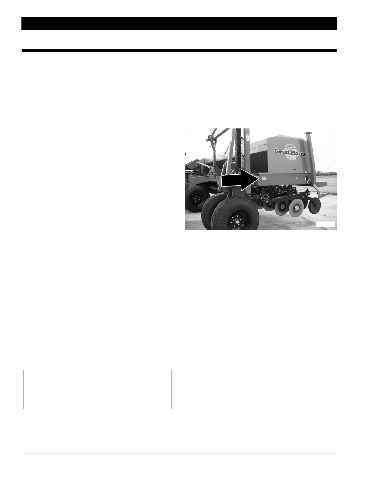
Great Plains dealer. The serial-number plate is located on
the front, left-hand side of the drill as shown in Figure A.
17315
Figure A
Serial Number
Record your drill model and serial number here for quick
reference:
Model Number: _________________________________
Serial Number: _________________________________
Your Great Plains dealer wants you to be satisfied with
your new machine. If you do not understand any part of
this manual or are not satisfied with the service received,
please take the following actions.
1. Discuss the matter with your dealership service man-
ager. Make sure they are aware of any problems so
they can assist you.
2. If you are still not satisfied, seek out the owner or gen-
eral manager of the dealership.
3. For further assistance write to:
Product Support
Great Plains Mfg. Inc., Service Department
PO Box 5060
Salina, KS 67402-5060
NOTE: Useful information related to the preceding topic.
2S-2600 and 2S-2600F Two-Section Folding Drill 195-200M-A 9/26/13
8
Page 11

Great Plains Mfg., Inc.
Section 1 Preparation and Setup
Section 1 Preparation and Setup
This section will help you prepare your tractor and drill for
use. You must adjust drill-tongue height to match your
tractor-drawbar height, hook up the drill hydraulics to the
tractor, and check that the hydraulics have been bled.
Prestart Checklist
1. Read and understand “Important Safety Information” beginning on page 1.
2. Check that all working parts are moving freely, bolts
are tight and cotter pins are spread.
3. Check that all grease fittings are in place and lubricated. Refer to Lubrication,“Maintenance and Lubrica-
tion,” page 48.
4. Check that all safety labels and reflectors arecorrectly
located and legible. Replace if damaged. Refer to
Safety Labels,“Important Safety Information,” page
4.
5. Inflate tires to recommended pressure as listed on
Tire Inflation Chart,“Appendix,” page 60. Tighten
wheel bolts as specified on Torque Values Chart,“Ap-
pendix,” page 60.
Tractor Hookup
1. Choose a drill-hitch option that is compatible with your
tractor drawbar.
The 2S-2600 has three hitch options:
• a clevis hitch,
• a small-hole, single-strap hitch or
• a large-hole, single-strap hitch.
Use the clevis hitch with tractors that have single-tang
drawbars.Use the single-strap hitch for tractors with
clevis drawbars. Always use a locking-style hitch pin
sized to match the holes in the hitch and drawbar.
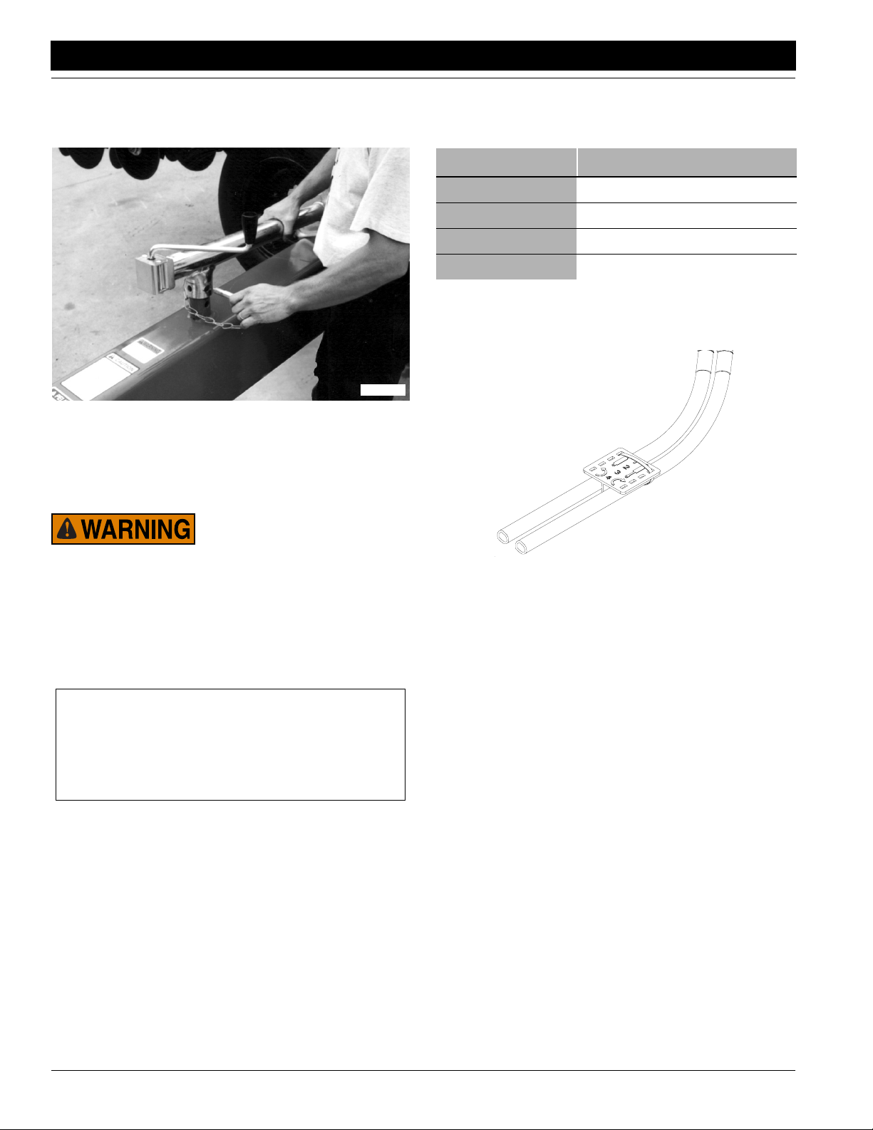
2. To adjust the drill hitch to match your tractor-drawbar
height, mount tongue jack on side of tongue as shown
in Figure 1-1. Use jack to raise drill tongue so lowest
hitch hole is 18 inches off ground.
You may be severely injured or killed by being crushed between
the tractor and drill. Do not stand or place any part of your
body between drill and moving tractor. Stop tractor engine and
set park brake before installing hitch pin.
This drill can have positive and negative tongue weight, which
can work the hitch pin loose during transport. To avoid serious
injury or death due to a road accident, always use a clevis hitch
or clevis drawbar with a locking-style hitch pin.
15564
Figure 1-1
Jack in Lifting Location
3. Bolt drill hitch onto drill tongue to match your tractordrawbar height. Refer to Figure 1-2. You can turn the
hitch over for a total of six different hitch heights.
NOTE: When hitching drill to a different tractor, check for a
difference in drawbar heights. If heights are different, readjust hitch height accordingly.
15623
9/26/13
Figure 1-2
Hitch Heights in Inches
2S-2600 and 2S-2600F Two-Section Folding Drill 195-200M-A
9
Page 12
Section 1 Preparation and Setup
Great Plains Mfg., Inc.
4. Securely attach safety chain to an anchor on tractor
capable of pulling drill.
5. Store jack on top of tongue as shown in Figure 1-3.
15563
Figure 1-3
Jack Storage Location
6. Plug drill electrical lead in tractor seven-pin connector.
If your tractor is not equipped with a seven-pin connector, contact your dealer for installation.
Hydraulic Hose Hookup
Great Plains hydraulic hoses are color coded to help you
hook up hoses to your tractor outlets. Hoses are color coded as follows.
Color Tie Hydraulic Function
Red Opener Lift
Blue Transport Lift
White Fold
Orange Marker
To distinguish hoses on the same hydraulic circuit, refer to
plastic hose holders. See Figure 1-4. Hoses under extended-cylinder symbol feed cylinder base ends. Hoses under
retracted-cylinder symbol feed cylinder rod ends.
Escaping fluid under pressure can penetrate the skin causing
serious injury. Avoid the hazard by relieving pressure before
disconnecting hydraulic lines. Use a piece of paper or cardboard, NOT BODY PARTS, to check for suspected leaks. Wear
protective gloves and safety glasses or goggles when working
with hydraulic systems. If an accident occurs, see a doctor immediately. Any fluid injected into the skin must be surgically removed within a few hours or gangrene may result.
IMPORTANT: To run drill on tractors with open-center
hydraulics or on tractors with fixed-displacement hydraulic pumps, you must install a Great Plains kit, part
number 194-143A. If you are not familiar with your
tractor hydraulics, consult your tractor dealer.
17641
Figure 1-4
Hydraulic Hose Label
1. Connect opener-lift hoses to circuit designated for hydraulic-motor control.
2. Connect transport-lift hoses to tractor remote valve.
3. Connect fold hoses to tractor remote valve.
NOTE: If your tractor has only two remote valves, you must
install a double-selector valve to combine the transport-lift
and opener-lift circuits. Refer to Two Outlet Hydraulic Kit,
“Options,” page 57.
2S-2600 and 2S-2600F Two-Section Folding Drill 195-200M-A 9/26/13
10
Page 13

Great Plains Mfg., Inc.
Section 1 Preparation and Setup
Bleeding the Hydraulics
To function properly, the hydraulics must be free of air. If
hydraulics have not been bled, they will operate with
jerky, uneven motions and could cause wings to drop
rapidly during folding or unfolding. If hydraulics were not
bled during initial implement setup or if you replace a
part in hydraulic system during the life of the drill, complete the following procedures.
Raising openers on unfolded, unhitched drill will cause drill
tongue to rise suddenly, which could cause serious injury or
death. Be certain that drill is hitched securely to your tractor
drawbar and the safety chain is securely attached to tractor
before raising openers and unfolding drill.
Escaping fluid under pressure can penetrate the skin causing
serious injury. Avoid the hazard by relieving pressure before
disconnecting hydraulic lines. Use a piece of paper or cardboard, NOT BODY PARTS, to check forsuspected leaks. Wear
protective gloves and safety glasses or goggles when working
with hydraulic systems. If an accident occurs, see a doctor
immediately. Any fluid injected into the skin must be surgically removed within a few hours or gangrene may result.
as needed. System capacity for entire drill is about 4
1/2 gallons.
2. Make sure opener frames are locked up in road posi-
tion. Refer to Opener Lock Up,“Operation Instruc-
tions,” page 20.
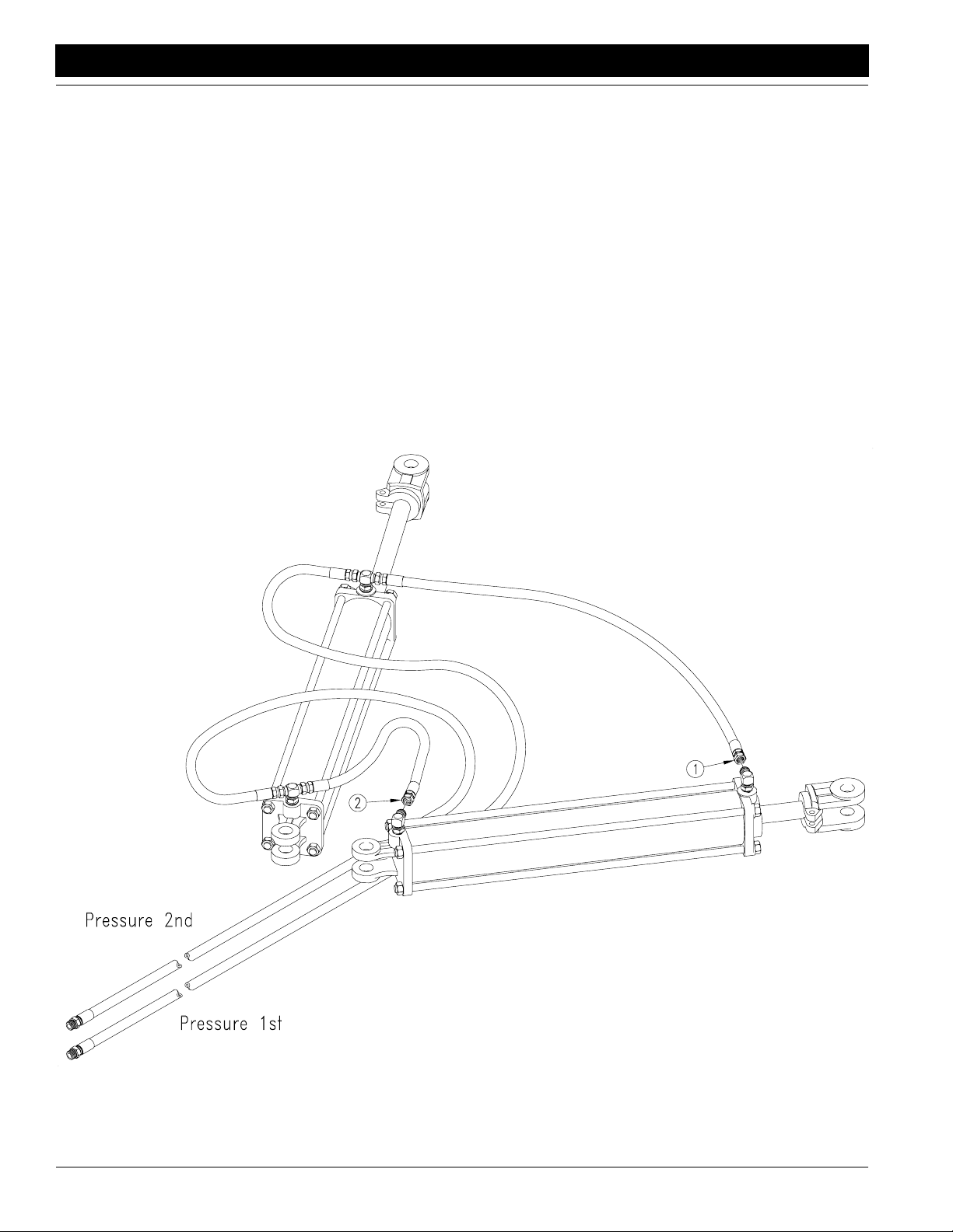
3. Turn knob on both pressure-control valves (1) com-
pletely counterclockwise, then turn valves clockwise
far enough to build up 1000 psi (about three turns).
4. Turn knob on bypass valve (2) completely clockwise
for no oil flow.
5. Loosen hose-end fittings (3) at the locations shown in
Figure 1-5.
NOTE: Do not loosen an O-ring fitting for bleeding. Bleeding air from an O-ring fitting will damage the seal.
6. Slowly supply oil to top side of pressure-control valves
until oil begins to appear at a loosened hose fitting. As
oil begins to appear at a fitting, tighten that fitting.
7. Slowly supply oil to bottom side of pressure-control
valves until oil begins to appear at remainingloosened
hose fitting. As oil begins to appear at the fitting, tighten fitting. Continue to supply oil to bottom side of pressure-control valves until all openers are raised
completely.
8. Move opener transport locks to field position and cycle
openers up and down ten times. Each time you lower
Bleeding Opener Lift Hydraulics
Refer to Figure 1-5.
1. Check hydraulic fluid level in
tractor reservoir and fill toprop-
er level. Add fluid to system
openers, hold tractor remote lever until opener circuit
builds up to pressure set at control valves.
9. After cycling openers, return opener transport locks to
road position.
Figure 1-5
Bleeding Opener Lift Hydraulics
9/26/13
22981
2S-2600 and 2S-2600F Two-Section Folding Drill 195-200M-A
11
Page 14
Section 1 Preparation and Setup
Great Plains Mfg., Inc.
Bleeding Fold Hydraulics
1. Check hydraulic fluid level in tractor reservoir and fill to
proper level. Add fluid to system as needed.
2. With drill unfolded and fold cylinders completely extended, disconnect rod-end pins and swing cylinders
so they will not contact anything when extended.
3. Loosen rod-end-hose fitting at elbow on left fold cylinder (1). See Figure 1-6.
NOTE: Do not loosen an O-ring fitting. Bleeding air from
an O-ring fitting will damage the seal.
4. Slowly supply oil to rod end of fold cylinders until oil
appears at loosened hose fitting. Tighten fitting and
completely retract fold cylinders.
5. With cylinders completely retracted, loosen base-endhose fitting at elbow on left fold cylinder (2). See Figure 1-6.
6. Slowly supply oil to base end of fold cylinders until oil
appears at loosened hose fitting. Tighten fitting and
cycle fold cylinders in and out several times.
7. Repin cylinder-rod clevis.
Figure 1-6
Bleeding Fold Hydraulics
2S-2600 and 2S-2600F Two-Section Folding Drill 195-200M-A 9/26/13
12
17299
Page 15

Great Plains Mfg., Inc.
Section 1 Preparation and Setup
Bleeding Transport Lift Hydraulics
1. Check hydraulic fluid level in tractor reservoir and fill to
proper level. Add fluid to system as needed.
2. With drill lowered into field position, loosen base-endhose fitting at elbow on right-hand transport-lift cylinder (1). See Figure 1-7.
3. Slowly supply oil to base end of transport-lift cylinders
until oil appears at the loosened hose fitting. As oil appears at fitting, tighten that fitting.
4. Completely extend transport-lift cylinders and immediately lock cylinders up by flipping up cylinder lock
channels on both transport-lift cylinders. Refer to Figure 2-4, page 14.
The hydraulics could fail, causing the openers to fall and crush
you. To prevent serious injury or death, always secure cylinder
lock channels over extended transport-lift cylinders before
working under openers.
5. When cylinder lock channels are in place, loosen rodend-hose fitting at elbow on left transport-lift cylinder
(2). See Figure 1-7.
6. Slowly supply oil to rod end of transport-lift cylinders
until oil appears at loosened hose fitting. As oil begins
to appear at fitting, tighten that fitting.
7. Extend transport-lift cylinders and remove cylinder
lock channels. Completely cycle transport-lift hydraulics several times.
Bleeding Marker Hydraulics
You may be injured if hit by a folding or unfolding marker.
Markers may fall quickly and unexpectedly if the hydraulics fail.
Never allow anyone near the drill when folding or unfolding
markers.
1. Make sure tractor hydraulic reservoir is full.
2. With markers unfolded in field position, crack hydraulic-hose fittings at base and rod ends of each marker
cylinder.
3. With tractor at idle speed, activate tractor hydraulic
valve forward until oil appears at one fitting. When oil
begins to seep out around a fitting, tighten that fitting.
Reverse the tractor hydraulic valve until oil appears at
opposite hose fitting and tighten that fitting.
4. If you have dual markers, activate your tractor hydraulic valve forward again until oil seeps out around one
fitting on the other marker cylinder and tighten that fitting. Reverse tractor hydraulic valve until oil seeps out
around remaining hose fitting and tighten it.
5. Fold and unfold markers slowly to work out all air. Use
caution when folding and unfolding markers for the
first time, checking for pinching and kinking of hoses.
17298
9/26/13
Figure 1-7
Bleeding Transport Lift Hydraulics
2S-2600 and 2S-2600F Two-Section Folding Drill 195-200M-A
13
Page 16

Section 2 Operating Instructions
Section 2 Operating Instructions
Great Plains Mfg., Inc.
This section covers general operating procedures. Experience, machine familiarity and the following information will
lead to efficient operation and good working habits. Always operate farm machinery with safety in mind.
Prestart Checklist
1. Lubricate drill as indicated under Lubrication,“Maintenance and Lubrication,” page 48.
2. Check all tires for proper inflation as indicated on Tire
Inflation Chart,“Appendix,” page 60.
3. Perform all beginning-of-season and daily service
items under Maintenance,“Maintenance and Lubri-
cation,” page 46.
4. Check the drill for worn or damaged parts. Repair or
replace them before going to the field.
5. Check all nuts, bolts and screws. Refer to Torque Val-
ues Chart,“Appendix,” page 60.
Folding
Crushing hazard – Bystanders could be crushed between the
folding drill boxes and the drill tongue. To avoid serious injury
or death, keep all bystanders well away during drill operation.
5. At front of drill, lock opener frames into road position
as shown in Figure 2-2.
15549
Figure 2-2
Opener Lock Up at Gauge Wheels
6. At rear of drill, lock opener frames into road position as
shown in Figure 2-3.
1. Park tractor and drill on level ground with tractor transmission in park. Be aware of clearance needed to fold
drill.
2. Hydraulically raise openers completely.
3. Raise drill with transport-lift cylinders until gauge
wheels are off ground and cylinders are extended
completely.
NOTE: While lifting for transport, the drill will flex in the
center before lifting gauge wheels off ground.
4. Slowly supply oil to rod end of fold circuit. Fold drill until both box frames are secured in folding latch.
17316
Figure 2-1
Folding Latch
17353
Figure 2-3
Opener Lock Up at Rear of Drill
7. At rear of drill, rotate cylinder lock channels over rods
on both transport-lift cylinders as shown in Figure 2-4.
15552
Figure 2-4
Cylinder Lock Channels Inserted for Transport
2S-2600 and 2S-2600F Two-Section Folding Drill 195-200M-A 9/26/13
14
Page 17

Great Plains Mfg., Inc.
Section 2 Operating Instructions
IMPORTANT: Make sure u-shaped spring clips in
lock channels clasp the cylinder rods securely. The
clips must hold the channels in position until cylinders
settle against the channels. Inspect clips regularly.
Adjust or replace clips as needed.
8. Allow transport-lift cylinders to settle against lock
channels.
9. Before transporting, check that hydraulic cylindersare
holding lock channels securely.
Unfolding
1. At front of drill, prop up latch pawl (1) as shown in Figure 2-5 so folding latch will release boxes.
1
17319
Figure 2-5
Latch Pawl Positioned for Folding
2. At front and rear of drill, position opener transport
locks in field position as shown in Figure 2-6.
15551
Figure 2-7
Cylinder Lock Channels Removed for Field Use
IMPORTANT: Do not lower openers until drill is unfolded or you will damage drill tires.
4. Slowly supply oil to base end of fold circuit. Unfold drill
by extending fold cylinders completely.
5. Completely retract transport-lift cylinders.
6. Completely lower openers to allow opener transport
locks to disengage.
Folding & Unfolding Quick Reference
To Fold Drill
1. Raise openers.
2. Extend transport cylinders.
3. Fold drill.
4. Lock opener frames and transport cylinders.
To Unfold Drill
1. Position latch pawl for release.
2. Unlock opener frames.
3. Unlock transport-lift cylinders.
4. Unfold drill.
15548
Figure 2-6
Opener Frames Unlocked
3. Supply oil to transport-lift cylinders until cylinders are
extended completely and drill is raised completely.
Rotate cylinder lock channels off cylinder rods as
shown in Figure 2-7.
9/26/13
IMPORTANT: Do not lower openers until drill is unfolded or you will damage drill tires.
5. Retract transport cylinders.
6. Lower openers.
2S-2600 and 2S-2600F Two-Section Folding Drill 195-200M-A
15
Page 18

Section 2 Operating Instructions
Great Plains Mfg., Inc.
Setting the Bypass Valve
A bypass valve is plumbed into the opener down pressure
circuit. See Figure 2-8. Tractors with load-sensing, closedcenter hydraulics require this bypass valve to protect the
tractor hydraulic system.
19045
Figure 2-8
Bypass Valve
If you are unsure what type of hydraulic system is on your
tractor, contact your tractor manufacturer.
Tractors with Open Center Hydraulics
Close bypass valve for no oil flow by turning knob on valve
clockwise completely. Always operate the drill with the bypass valve closed.
Tractors with Pressure Compensating Closed Center Hydraulics (PC Closed)
Close bypass valve for no oil flow by turning knob on valve
clockwise completely. Always operate the drill with the bypass valve closed.
Tractors with Load Sensing Closed Center Hydraulics (LS Closed) Pressure Flow Compensating (PFC) Systems
IMPORTANT: Failure to use the bypass valve on loadsensing tractors may cause major tractor damage.
1. Close bypass valve for no oil flow by turning knob on
valve clockwise completely.
2. With tractor at half throttle, adjust flow-control valve on
tractor so openers raise and lower at a reasonable
speed. Keep tractor at one-half throttle for remaining
steps.
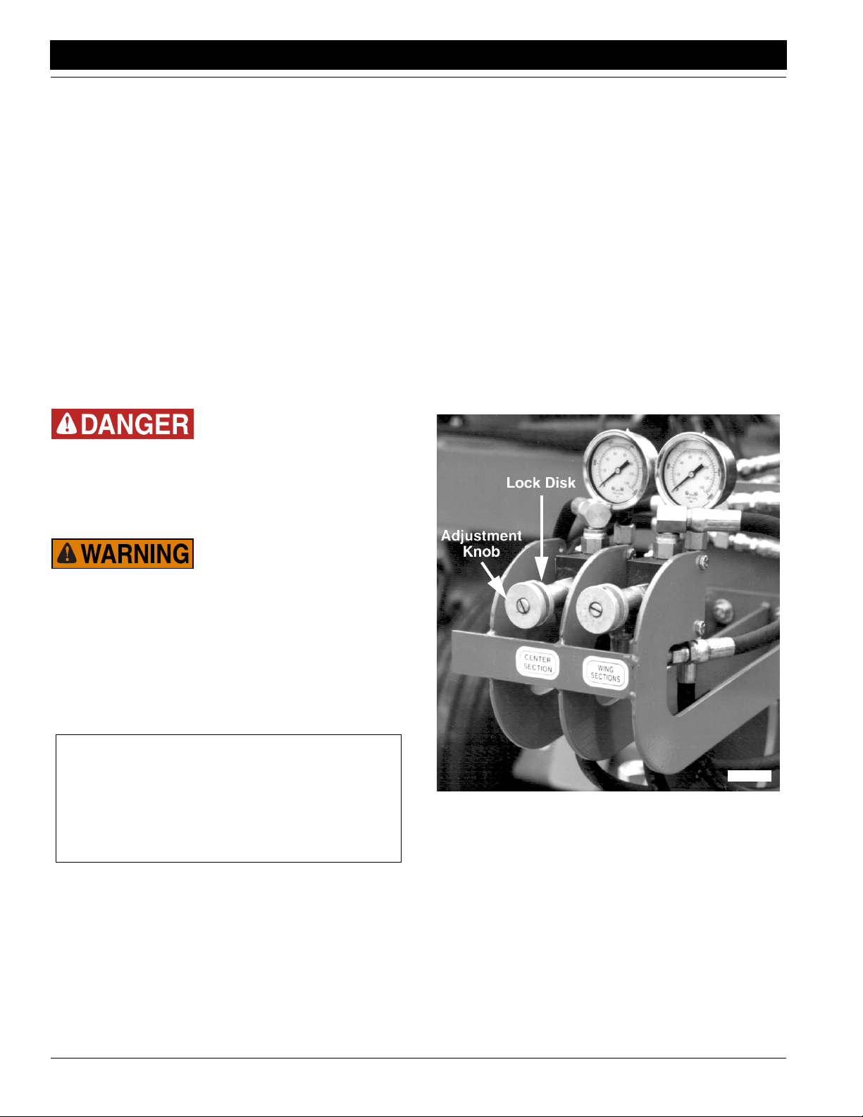
4. Adjust pressure-control valves on drill for opener
down pressure so gauges are at 1800 psi. See Figure
2-11.
15557
Figure 2-9
Pressure Control Valves
5. While watching gauges on drill, slowly turn knob on
bypass valve counterclockwise. Adjust bypass valve
just until needles on gauges begin to move down from
1800 psi. Lock bypass valve at this setting. (See also
note below.)
6. Adjust pressure-control valves on drill to desired
opener down pressure as explained under Opener
Down Pressure, beginning on page 33.
NOTE: The higher the bypass pressure, the greater the
potential for oil heating and premature tractor damage. At
the same time, for proper opener operation the bypass
valve must be set at least 300 psi above the opener downpressure setting when the tractor is at one-half throttle.
Therefore, you should set the bypass valve as low as possible while staying at least 300 psi above the opener down
pressure setting.
While 1800 psi is a good starting point for setting the bypass valve, if you consistently operate the drill with low
opener down pressure you can set the bypass valve below
1800 psi. If you consistently operate the drill with very high
opener down pressure, you may need a bypass-valve setting above 1800 psi.
NOTE: The faster openers raise and lower, the greater potential for oil heating, premature wear or tractor damage.
Keep tractor at one-half throttle for remaining steps.
3. Engage tractor hydraulics and lower openers. Lock
hydraulic lever on tractor for continuous operation.
2S-2600 and 2S-2600F Two-Section Folding Drill 195-200M-A 9/26/13
16
Page 19

Great Plains Mfg., Inc.
Section 2 Operating Instructions
Adjusting the Counter Balance Valve
On the stem of the valve there is a rubber cap that protects
the threads of an adjustment stem. This stem is locked in
place with a hex nut. To adjust the valve, loosen the nut
and turn the stem using an Allen wrench.
Screwing the stem in (clockwise) pushes on a spring
which supplements the pilot line’s force on an internal piston. More spring force will let the valve open with a low pilot pressure. Less spring force will require higher pilot
pressure to open the valve.
Note: With the screw turned in fully, the spring will develop
enough force on the piston to unlock the valve, even with
no pilot pressure, causing the openers to settle.
Raise and lower the drill several times then hold hydraulic
down pressure on the openers to purge air from the system and to warm the oil. Repeat.
Raise the openers. Observe the openers closely to detect
settling. If the openers remain up, no valve adjustment is
needed.
If the openers settle, the stem is screwed in too far. Gently
back the stem out until it stops, then screw it in one turn.
Generally this is a good starting point. Check for settling.
Backing the stem out will lock the valve, screwing it in too
far can cause it to unlock.
A small increase in lowering speed can be achieved by
screwing the stem in.
9/26/13
2S-2600 and 2S-2600F Two-Section Folding Drill 195-200M-A
17
Page 20
Section 2 Operating Instructions
Great Plains Mfg., Inc.
Opener Operation
The openers are raised and lowered on their own hydraulic circuit. When used with an active hydraulic system, constant hydraulic down pressure is placed on openers for
even soil penetration across the drill. To operate openers
with live hydraulic power, always connect the opener-lift
hoses to the circuit designated for hydraulic-motor control.
To achieve proper opener flotation, the opener hydraulic
circuit must be powered by an active hydraulic system. An
active hydraulic system requires a tractor with closed-center hydraulics or pressure-flow compensated hydraulics
powered by a variable displacement hydraulic pump.
To run drill on tractors with open-center hydraulics or on
tractors with fixed-displacement hydraulic pumps, you
must install a Great Plains kit, part number 194-143A.
Contact your Great Plains dealer for ordering information.
If you are not familiar with your tractor's hydraulics, consult
your tractor dealer.
Crushing hazard – You will be seriously injured or killed if you
are caught between raising openers and drill frame. Always
stop tractor engine, set park bake, and remove key before adjusting or servicing openers. Keep all bystanders well away
during drill operation.
John Deere 8000 Series tractors: Set timer to continuous. Push lever forward until detent clicks.
Case-IH Magnum tractors: Lock lever forward in
detent position. You may need to turn up detent pressure to its maximum setting. Do not tie hydraulic lever
past detent position with a strap. See your tractor
dealer for hydraulic-system details.
Other tractors: Lock lever forward in detent position.
You may need to turn up detent pressure to maximum
or use a mechanical detent holder to hold lever forward. See your tractor dealer for proper means of providing constant flow to openers.
2. Set opener down pressure. There is one pressurecontrol valve for openers on center of drill and one for
openers on outside ends of drill. See Figure 2-12. Initially set down pressure at 800 psi, then adjust as field
conditions warrant. For more information on adjusting
hydraulic down pressure, refer to Opener Down Pres-
sure,“Adjustments,” page 33.
Escaping fluid under pressure can penetrate the skin causing
serious injury. Avoid the hazard by relieving pressure before
disconnecting hydraulic lines. Use a piece of paper or cardboard, NOT BODY PARTS, to check for suspected leaks. Wear
protective gloves and safety glasses or goggles when working
with hydraulic systems. If an accident occurs, see a doctor immediately. Any fluid injected into the skin must be surgically removed within a few hours or gangrene may result.
Opener Operation for Active Hydraulic Systems
IMPORTANT: Tractors with load-sensing hydraulics
must use the bypass valve to operate the 2S-2600. Failure to use the bypass valve can cause major tractor
damage. Before adjusting opener down pressure, set
bypass valve as explained under Setting the Bypass
Valve, page 16.
1. Lock hydraulic lever forward during field operation for
constant hydraulic flow to openers.
John Deere tractors with Sound-Gard ® Body: Use
lever lock clip, John Deere part number R52667, to
lock lever forward. See your tractor dealer for clip purchase and installation.
John Deere 7000 Series tractors: Rotate valve
detent selector to motor position to lock lever in forward position.
15557
Figure 2-10
Pressure Control Valves
2S-2600 and 2S-2600F Two-Section Folding Drill 195-200M-A 9/26/13
18
Page 21

Great Plains Mfg., Inc.
Section 2 Operating Instructions
3. Set opener seeding depth by adjusting press-wheel
height. To adjust, first raise openers slightly, then lift
and slide T-handles on top of openers as shown in Figure 2-11. Adjust all press wheels to the same height.
• For shallower seeding, slide T-handles toward drill.
• For deeper seeding, slide T-handles away from drill.
While seeding, remember:
• Raise openers before turning. Never back up or turn
sharply with openers in ground. Doing so will plug openers and may damage equipment.
• For information on opener adjustments, see Opener
Down Pressure and Opener Depth,“Adjustments,”
starting on page 33. For more information on troubleshooting opener problems, see “Troubleshooting,”
page 44.
15659
Figure 2-11
Press Wheel Adjustment
Priority Flow Hydraulic Systems
On some tractors with load-sensing hydraulics, the #1 circuit is capable of taking nearly 100 percent of available hydraulic flow. Operating the openers or markers on circuit
#1 will starve the other circuit, making one function inoperable.
To operate markers and constant opener down pressure
at the same time, connect the openers to circuit #2 and the
markers to circuit #3.
Opener Operation for Non-Active Hydraulic Systems
IMPORTANT: Tractors with load-sensing hydraulics
must use the bypass valve to operate the 2S-2600. Failure to use the bypass valve can cause major tractor
damage. Before adjusting opener down pressure, set
bypass valve as explained under Setting the Bypass
Valve, page 16.
To run drill with open-center hydraulics or fixed-displacement hydraulic pumps requires a Great Plains kit, part
number 194-143A. After installing the kit, refer to the following instructions for opener operation.
1. Lower opener frames by pushing forward on tractor
hydraulic lever. Lock lever temporarily in this position
while adjusting opener down pressure.
2. With tractor hydraulic lever locked forward, set opener
down pressure. There is one pressure-control valve
for openers on center of drill and one for openers on
outside ends of drill. See Figure 2-8. Initially set down
pressure at 800 psi, then adjust as field conditions
warrant. For more information on adjusting opener
hydraulic down, refer to Opener Down Pressure,
“Adjustments,” page 33.
3. After opener down pressure is set, return tractor hydraulic lever to neutral. This locks in the selected pressure, and opener frames will remain fixed in this
position.
IMPORTANT: Open-center tractors and tractors with
fixed-displacement pumps are not designed to provide a continuous supply of pressurized oil to remote
valves. Locking hydraulic lever forward on these tractors can cause overheating of hydraulic oil and tractor damage. After setting opener down pressure,
always return hydraulic lever to neutral.
4. Set opener seeding depth by adjusting press-wheel
height. To adjust, first raise openers slightly, then lift
and slide T-handles on top of openers as shown in Figure 2-11. Adjust all press wheels to the same height.
• For shallower seeding, slide T-handles toward drill.
• For deeper seeding, slide T-handles away from drill.
While seeding, remember:
• When approaching rough terrain where you need active
hydraulics to maintain even opener penetration, push
tractor hydraulic lever forward momentarily. As soon as
you return to level ground, return lever to neutral. Do not
activate tractor hydraulic lever for more than 20 seconds
at a time, once every 2 minutes. Always wait until tractor
and drill are on level ground before returning lever to
neutral. You can bump tractor hydraulic lever forward
any time on level ground to assure the preset pressure
is correctly locked in and to reset the system.
• Raise openers before turning. Never back up or turn
sharply with openers in ground. Doing so will plug openers and may damage equipment.
• Each time you lower openers, hold tractor remote hy-
draulic lever forward for a few seconds to recharge circuit, then return lever to neutral. Return lever to neutral
only when tractor and drill are on level ground.
• For information on opener adjustments, see Opener
Down Pressure and Opener Depth,“Adjustments,”
starting on page 33. For more information on troubleshooting opener problems, see “Troubleshooting,”
page 44.
9/26/13
2S-2600 and 2S-2600F Two-Section Folding Drill 195-200M-A
19
Page 22

Section 2 Operating Instructions
Great Plains Mfg., Inc.
Opener Lock Up
Openers must be locked up for transport and drill maintenance. To lock up openers, position opener-transport-lock
handles on both drill sections in road position, then raise
openers completely. See .
To unlock openers, position opener-transport-lock handles in field position, then raise openers completely.
NOTE: Opener-transport-lock handles can be moved with
openers up or down, but transport locks will only engage
after openers are raised completely and disengage after
openers are lowered completely.
15549
Fertilizer Box Operation
The 2S-2600F is equipped with a fertilizer compartment
so you can plant seed and apply fertilizer in the same field
pass. Use only dry, granular fertilizer in the fertilizer box.
1. Clean any seed or debris from fertilizer compartment.
2. Adjust seed and fertilizer compartments to desired capacity. The 2S-2600F is equipped with standard dividers that partition drill boxes into 60 percent seed and
40 percent fertilizer. If your drill is outfitted with optional offset dividers, you can change the seed-to-fertilizer
ratio. Refer to Seed and Fertilizer Capacity,“Adjust-
ments,” on page 41.
3. Calibrate fertilizer-application rate as explained under
Fertilizer Rate Calibration,“Adjustments,” page 29.
4. Check that divider door is closed so seed and fertilizer
cannot pass between compartments. See Figure 2-
16.
5. Check that fertilizer cleanout door is latched securely
(1) as shown in Figure 2-14. Close all door latches before loading fertilizer compartment.
Figure 2-12
Opener Lock Up
Point Row Operation
The point-row option allows you to raise and lower openers on one drill section independent of the others. To raise
and lower openers on both sections together, flip power
switch (1) so master-lift-control light (2) is on. Raise or lower all openers by moving the switch under the light.
To raise and lower openers on one section independent of
the other, flip power switch so section-control-light (3) is lit.
Raise and lower openers on a section by moving the
switches under the light.
1
16377
Figure 2-14
Cleanout Door Latched
6. Open lid over fertilizer compartment and swivel back
until it rests against open drill-box lid. See Figure 2-15.
The fertilizer lid serves as a spill guard to keep fertilizer out of the seed compartment.
16375
17060
Figure 2-13
Point-Row Control Monitor
7. Fill fertilizer compartment.
Figure 2-15
Spill Lid
NOTE: Turn point row power switch off when tractor is off.
2S-2600 and 2S-2600F Two-Section Folding Drill 195-200M-A 9/26/13
20
Page 23

Great Plains Mfg., Inc.
Section 2 Operating Instructions
Seeding with Both Compartments
1. Clean out boxes as explained under 2S-2600F Clean
Out,“Maintenance and Lubrication,” on page 46.
2. Open divider door between seed and fertilizer compartments. To open door, loosen black knobs (1)
shown in Figure 2-16. Loosen knobs until bent clips
can be turned off door. When all bent clips have been
turned, swivel door back against fertilizer-tray opening.
1
1
1
16383
Figure 2-16
Divider Door
3. Use vinyl washout cover to hold divider door open as
shown in Figure 2-17.
16380
Figure 2-17
Divider Door Secured
4. To avoid unnecessary wear, remove fertilizer drive
chains.
Shaft Monitor Operation
To operate shaft monitor, turn system on by activating onoff switch on monitor head. If seed-cup shaft is turning,
both of the lights will be on and the alarm will not sound.
If either seed-cup shaft stops for 30 seconds, an alarm will
sound and a light on the monitor will flash designating the
failed shaft.
The 30-second delay is to prevent nuisance alarms when
turning at the end of the field. If a failure does occur and an
alarm sounds, remember you have traveled for 30 seconds without planting.
Marker Operation
Optional markers are equipped with a double-selector
valve to combine the transport-fold circuit with the marker
circuit.
After drill is unfolded for field operation, shift double-selector valve to marker circuit as shown in Figure 2-18. Before
operating markers, make sure they are properly bled as
described in Bleeding the Hydraulics, “Drill Preparation
and Setup,” page 11.
15550
Figure 2-18
Shifting the Double Selector Valve
To operate a single marker, activate tractor remote hydraulic lever to move marker in desired direction.
Single markersare equipped with a needle valve to control
marker folding speed. Excessive folding speed can damage markers, so adjust needle valve to a safe operating
speed as described under Marker Adjustments, “Adjust-
ments,” page 21.
Dual markers are equipped with a sequence valve to control lift sequence. Starting with both markers up, the sequence is:
1. Activate hydraulic lever; right marker lowers while left
marker stays up.
2. Reverse hydraulic lever; right marker raises while left
marker stays up.
3. Activate hydraulic lever; left marker lowers while right
marker stays up.
4. Reverse hydraulic lever; left marker raises while right
marker stays up.
5. Pattern repeats.
Folding speed of dual markers is adjusted with adjustment
screws on sequence-valve body. Excessive folding speed
can damage markers, so adjust markers to a safe folding
speed as described under Marker Adjustments, “Adjust-
ments,” page 21.
9/26/13
2S-2600 and 2S-2600F Two-Section Folding Drill 195-200M-A
21
Page 24
Section 2 Operating Instructions
Great Plains Mfg., Inc.
Transporting
Towing the drill at high speeds or with a vehicle that is not
heavy enough could lead to loss of vehicle control. Loss of vehicle control could lead to serious road accidents, injury and
death. To reduce the hazard:
• Do not exceed 20 mph.
• Do not tow a drill that,when fully loaded,weighs more than
1.5 times the weight of the towing vehicle.
Before transporting the drill check the following items.
1. Transport only with a tractor of proper size. See
“Specifications,” page 59.
2. Hitch drill securely to tractor. Always use a lockingstyle pin sized to match holes in hitch and drawbar
(minimum of 1-inch diameter).
3. Attach safety chain to an anchor on tractor capable of
pulling drill.
4. Plug drill safety lights into tractor seven-pin connector.
5. Make sure drill is folded properly. Refer to Folding,
page 14.
6. Lock openers up into road position. Refer to Opener
Lock Up, page 20.
7. Secure cylinder lock channels on transport-cylinder
rods and allow cylinders to settle against the channels. Refer to Folding, page 14.
Marker Transportation
Always transport markers folded flat. Make sure second
marker section rests securely on transport carrier.
Parking
For information on long-term storage, refer to Storage,
“Maintenance and Lubrication,” page 46.
Parking with Drill Unfolded
This drill has a negative tongue weight when unfolded and
openers are raised. Lower parking stand, lower openers and remove hydraulic down pressure before unhitching the drill in the
unfolded position. Unhitching in the unfolded position with the
openers raised could result in sudden elevation of the tongue,
causing injury or death.
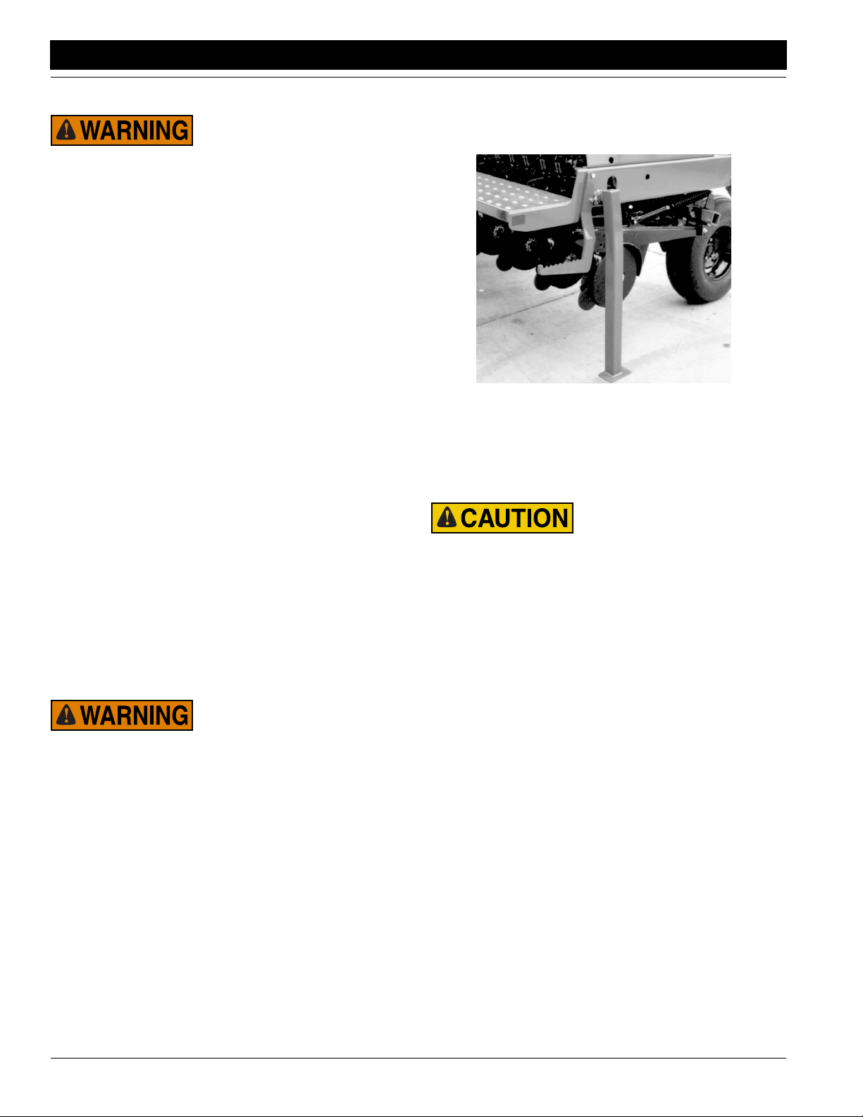
1. Remove jack from its storage location on top of tongue
and pin it on post on left side of tongue as shown in
Figure 1-1, page 9. Extend jack until weight of tongue
is on jack.
2. Lower parking stands located on outer ends of drill by
unpinning keeper pin and rotating stands down. See
Figure 2-19. Place a block under foot of stand if it does
not contact ground.
15565
Figure 2-19
Parking Stand
3. Lower openers and reduce hydraulic down pressure
to zero.
4. Unplug drill hydraulic hoses and electrical lines from
tractor.
Use caution when removing the hitch pin. Slight tongue elevation may occur.
5. Remove hitch pin and safety chain from tractor drawbar.
NOTE: After unhitching the unfolded drill, the tongue may
rise above tractor-drawbar height. Lower tongue by connecting the opener-lift circuit and pressurizing openers.
Parking with Drill Folded
1. Raise, lock and fold drill into transport position.
2. Park drill on a level, solid area.
3. Remove jack from its storage location on top of tongue
and pin it on post on left side of tongue as shown in
Figure 1-1, page 9. Extend jack until weight of tongue
is on jack. If ground is soft, place a board or plate under jack to widen ground-contact area.
4. Unplug hydraulic hoses and electrical lines from tractor.
5. Remove hitch pin and safety chain from tractor drawbar.
2S-2600 and 2S-2600F Two-Section Folding Drill 195-200M-A 9/26/13
22
Page 25

Great Plains Mfg., Inc.
Section 3 Adjustments
Section 3 Adjustments
This section covers basic field and maintenance adjustments. Before going to the field, set the seeding rate and
adjust seeding depth. Check drive chains and disk scrapers periodically during the season.
Seed Rate Calibration
Calibrating the seeding rate requires four steps:
• changing drive sprockets,
• setting seed-rate handle,
• positioning seed-cup doors, and
• checking seeding rate.
Refer to the seed-rate charts. These charts list proper
sprocket sizes and seed-rate-handle settings for various
seeds and seeding rates.
The seed-rate charts are based on cleaned, untreated
seed of average size and test weight. The charts are
based on 9.5L-15, 6-ply, rib implement tires. Many factors
will affect seeding rates including foreign material, seed
treatment, seed size, seed weight, field conditions, tire
pressure and test weight. You likely will need to make minor adjustments. Set and check the seeding rate using the
procedures below, then readjust the rate as necessary.
For correct drive type, refer to seed-rate charts beginning
on page 25. The charts lists drive types as 1, 2, 3 or 4. Refer to the following table for correct-sized sprocket for each
drive type.
To change drive types, loosen idlers and remove drive
chain shown in Figure 3-1. Remove lynch pin and rearrange sprockets on shaft.
15559
Figure 3-1
Drive Type Sprockets
Reroute drive chain as shown in Figure 3-2. Set same
drive type on both drill sections. Be sure chain is installed
with the chain connector link retainer towards the centerline and the clip opening (split end) faces the opposite way
of the chain travel.
Drive
Type
Type 1 72-tooth Slowest
Type 2 34 tooth Two Times Faster Than Type 1
Type 3 23-tooth Three Times Faster Than Type 1
Type 4 14-tooth Five Times Faster Than Type 1
Sprocket Speed
Figure 3-2
Drive Type Sprockets and Chain Routings
9/26/13
2S-2600 and 2S-2600F Two-Section Folding Drill 195-200M-A
23
Page 26

Section 3 Adjustments
Great Plains Mfg., Inc.
Setting Seed-Rate Handle
There is a seed-rate-adjustment handle for each drill section. See Figure 3-3. Position handles to the setting indicated on the seed-rate charts. To adjust handle, loosen
wing nut under handle and slide handle until indicator lines
up with correct setting.
15561
Figure 3-3
Seed Rate Adjustment Handle
Positioning Seed-Cup Doors
For wheat and other small seeds, move seed-cup-door
handles to highest position. For soybeans and other large
seeds, lower handles to second position. If excessive seed
cracking occurs, lower handles to third position. For seedcup clean out, move handles to fourth, wide open. Make
sure all handles are in the same position before drilling.
Checking Seeding Rate
You may be severely injured or killed by being crushed from a
falling implement or openers. Always have transport locks in
place and frame sufficiently blocked up when working on the
drill.
1. Jack up drive gauge wheel(s) and rotate them to see
that seed cups and drives are working properly and
free from foreign material.
2. Check that your gauge-wheel tires are 9.5L - 15, 6-ply
rib implement and properly inflated. Refer to Tire Infla-
tion Chart, “Appendix,” page 60.
3. Record weight of an empty container large enough to
hold seed metered for one acre.
4. Place several pounds of seed over three seed cups on
an outside end of drill box. Pull seed tubes off of
these three openers.
5. Turn drive wheel several times to fill seed cups. Turn
wheel until seed drops to ground from each seed cup.
6. Place empty container under three tubes to gather
metered seed.
7. Turn drive wheel until one acre is tallied on acremeter
(203 wheel rotations). While turning, check that cups
have plenty of seed coming into them.
8. Weigh metered seed. Subtract initial weight of container. Divide by three. Multiply by number of openers
on your drill to determine total pounds-per-acre seeded. If this figure is different than desired, reset sprockets accordingly.
NOTE: You may want to repeat calibration procedure if
your results vary greatly from seed-rate chart.
9. When drilling, check seeding rate by noting acres
drilled, amount of seed added to drill and seed level in
drill box. If you are seeding more or less than desired,
adjust rate slightly to compensate for field conditions.
15555
Figure 3-4
Seed Cup Door Adjustment
2S-2600 and 2S-2600F Two-Section Folding Drill 195-200M-A 9/26/13
24
Page 27

Great Plains Mfg., Inc.
Section 3 Adjustments
Seed Rate Charts (pounds per acre)
Setting number
Alfalfa
Drive Type 1
(Based on
60#/bu)
Barley
Drive Type 1
(Based on
51#/bu)
Barley
Drive Type 2
(Based on
51#/bu)
Barley
Drive Type 4
(Based on
51#/bu)
Buck Wheat
Drive Type 3
(Based on
48#/bu)
Canola or
Rape
Drive Type 1
(Based on
51#/bu)
Flax or
Sudan
Drive Type 1
(Based on
55#/bu)
6" 2 6 8 12 15 19 23 27 32 37 41 45 50 54 59 63 69 74 79 82 84
7.5" 2 4 7 10 12 15 18 22 25 29 33 36 40 43 47 51 55 59 63 65 67
Spacing
10" 1 3 5 7 9 12 14 16 19 22 25 27 30 33 35 38 41 44 48 49 50
6" 2 5 8 11 14 18 22 26 30 35 39 43 48 53 57 62 66 69 73 73 74
7.5" 24691215182124283135384246495255585959
Spacing
10" 1 3 5 6 9 11 13 16 18 21 23 26 29 32 34 37 39 42 44 44 44
6" 4 9 16 22 30 37 45 54 62 71 76 87 96 104 114 123 133 142 152 154 156
7.5" 3 7 13 17 24 30 36 43 49 57 64 70 77 83 91 98 106 114 121 123 125
Spacing
10" 2 5 10 13 18 22 27 32 37 43 48 52 58 63 68 74 80 85 91 92 94
6" 9 21 39 53 73 90 110 131 151 174 194 213 234 255 278 300 325 348 371 377 382
7.5" 7 17 31 42 58 72 88 105 121 139 155 170 188 204 222 240 260 279 297 301 306
Spacing
10" 5 13 23 32 44 54 66 79 91 104 117 128 141 153 167 180 195 209 222 226 230
6" 0 11 21 29 42 52 65 78 92 107 123 136 150 165 180 195 209 224 240 242 245
7.5" 0 9 17 24 34 42 52 62 74 85 99 109 120 132 144 156 167 179 192 194 196
Spacing
10" 0 7 13 18 25 31 39 47 55 64 74 81 90 99 108 117 126 134 144 145 147
6" 0 4 8 11 14 18 21 25 29 32 36 39 43 47 51 54 59 63 68 69 71
7.5" 03691114172023262932343740434750545557
Spacing
10" 0 2 5 6 9 11 13 15 17 19 22 24 26 28 30 33 35 38 41 42 43
6" 0 4 8 12 16 20 24 28 33 37 42 46 50 54 59 65 70 76 82 83 85
7.5" 03791316192326303437404447525661666768
Spacing
10” 0 2 5 7 10 12 15 17 20 22 25 27 30 33 35 39 42 45 49 50 51
0 5 10 15 20 25 30 35 40 45 50 55 60 65 70 75 80 85 90 95 100
Millet
Drive Type 1
(Based on
60#/bu)
Milo
Drive Type 1
(Based on
60#/bu)
Oats
Drive Type 3
(Based on
37#/bu)
Peas
Drive Type 3
(Based on
61#/bu)
Pinto Bean
Drive Type 1
(Based on
61#/bu)
6" 1 5 8 12 16 20 23 27 32 36 40 44 49 52 57 62 66 71 76 77 78
7.5" 14791316192225293235394246495357616263
Spacing
10" 1 3 5 7 9 12 14 16 19 21 24 26 29 32 34 37 40 43 46 46 47
6" 0 5 9 13 18 23 28 34 39 45 52 57 63 69 75 81 87 92 98 100 102
7.5” 0 4 7 10 14 18 22 27 31 36 41 45 50 55 60 65 69 73 78 80 82
Spacing
10" 0 3 5 8 11 14 17 20 23 27 31 34 38 41 45 49 52 55 59 60 61
6" 0 5 12 17 24 32 39 47 55 63 72 80 88 96 105 113 121 130 139 140 140
7.5" 0 4 10 14 19 25 31 37 44 51 58 64 70 77 84 90 97 104 111 112 112
Spacing
10" 0 3 7 10 14 19 23 28 33 38 43 48 53 58 63 68 73 78 83 84 84
6" 0 0 19 34 52 69 84 102 119 137 154 169 186 202 218 235 251 266 281 283 284
7.5” 0 0 15 27 42 55 67 82 95 110 123 136 149 161 175 188 201 213 225 226 227
Spacing
10" 0 0 11 20 31 41 50 61 71 82 93 102 112 121 131 141 151 160 169 170 171
6" 0 0 9 13 17 24 30 35 41 47 53 58 64 69 74 81 85 91 97 96 96
7.5" 0 0 7 10 14 19 24 28 33 38 42 47 51 55 60 65 68 73 77 77 77
Spacing
10" 0 0 5 8 10 14 18 21 25 28 32 35 38 41 45 49 51 54 58 58 58
9/26/13
2S-2600 and 2S-2600F Two-Section Folding Drill 195-200M-A
25
Page 28

Section 3 Adjustments
Seed Rate Charts (pounds per acre)
Great Plains Mfg., Inc.
Setting number
Rice
Short Grain
Drive Type 3
(Based on
43#/bu)
Rice
Short Grain
Drive Type 4
(Based on
43#/bu)
Rice
Long Grain
Drive Type 3
(Based on
47#/bu)
Rice
Long Grain
Drive Type 4
(Based on
47#/bu)
Rye
Drive Type 1
(Based on
57#/bu)
Soybeans
Drive Type 1
(Based on
58#/bu)
Soybeans
Drive Type 2
(Based on
58#/bu)
6" 3 11 18 28 38 46 56 64 73 84 96 107 117 128 139 148 167 165 174 174 174
7.5" 2 9 14 23 31 37 44 51 59 67 77 85 94 102 111 118 125 132 139 139 139
Spacing
10" 2 7 11 17 23 27 33 38 44 50 57 64 70 77 83 89 94 99 105 105 105
6" 5 18 29 46 63 74 91 104 120 137 156 174 191 209 226 241 255 269 284 284 284
7.5" 4 14 24 37 50 60 72 83 96 109 125 139 153 167 181 193 204 215 227 227 227
Spacing
10" 3 11 18 28 38 45 54 62 72 82 94 105 115 125 136 145 153 162 170 170 170
6" 0 0 13 22 32 42 53 61 71 81 90 98 107 116 125 135 144 153 161 167 173
7.5" 0 0 11 17 25 34 42 49 57 65 72 79 85 92 100 108 116 123 129 134 138
Spacing
10" 0 0 8 13 19 25 32 37 42 49 54 59 64 69 75 81 87 92 97 100 104
6" 0 0 22 35 52 68 86 100 115 132 146 160 174 188 204 220 235 250 263 273 282
7.5" 0 0 17 28 41 55 69 80 92 105 117 128 139 151 163 176 188 200 210 218 226
Spacing
10” 0 0 13 21 31 41 52 60 69 79 88 96 104 113 123 132 141 150 158 164 169
6" 0 3 8 13 19 24 28 35 41 47 53 58 63 68 74 81 87 94 101 102 102
7.5" 0 2 6 10 15 19 22 28 33 38 42 46 50 55 59 64 69 75 81 81 82
Spacing
10" 0 2 5 8 11 14 17 21 24 28 32 35 38 41 44 48 52 56 61 61 61
6" 0 3 8 13 19 23 29 34 39 45 49 55 61 66 71 77 82 87 93 93 93
7.5" 0 2 6 11 15 19 23 27 31 36 40 44 49 53 57 62 65 70 74 74 75
Spacing
10" 0 2 5 8 12 14 17 20 24 27 30 33 37 40 43 46 49 52 56 56 56
6" 0 6 16 27 40 48 59 69 80 92 102 114 125 136 147 158 167 179 190 191 192
7.5” 0 5 13 22 32 38 47 55 64 73 81 91 100 109 118 127 134 143 152 153 153
Spacing
10" 0 4 10 16 24 29 35 42 48 55 61 68 75 82 88 95 101 107 115 115 115
0 5 10 15 20 25 30 35 40 45 50 55 60 65 70 75 80 85 90 95 100
Soybeans
Drive Type 3
(Based on
58#/bu)
Soybeans
Drive Type 4
(Based on
58#/bu)
Sun
flowers
Drive Type 1
(Based on
28#/bu)
Wheat
Drive Type 2
(Based on
64#/bu)
Wheat
Drive Type 3
(Based on
64#/bu)
WheatGrass
Drive Type 1
(Based on
23#/bu)
6" 0 12 23 40 60 71 89 101 116 131 148 164 181 196 214 228 248 265 284 284 284
7.5" 0 9 18 32 48 57 71 81 93 105 119 131 145 157 171 182 199 212 227 227 227
Spacing
10" 0 7 14 24 36 42 53 61 70 79 89 98 108 118 128 137 149 159 170 170 170
6" 0 19 37 66 97 115 145 165 190 214 241 267 295 320 348 371 405 433 463 463 464
7.5" 0 15 29 53 78 92 116 132 152 171 193 214 236 256 279 297 324 346 370 371 371
Spacing
10" 0 11 22 40 58 69 87 99 114 128 145 160 177 192 209 223 243 260 278 278 278
6" 0 0 2 4 6 8 11 13 15 18 20 23 25 27 30 32 34 36 38 39 41
7.5" 00235791012141618202224262729313233
Spacing
10" 0 0 1 3 4 5 6 8 9 11 12 14 15 16 18 19 20 22 23 24 24
6" 0 13 22 30 40 50 57 70 80 91 105 115 127 140 152 164 177 190 203 205 206
7.5" 0 10 18 24 32 40 46 56 64 73 84 92 102 112 122 131 142 152 162 164 165
Spacing
10" 0 8 13 18 24 30 34 42 48 55 63 69 76 84 91 99 106 114 122 123 124
6" 0 16 31 45 60 74 88 104 120 137 153 168 186 202 220 240 256 274 290 297 299
7.5" 0 13 25 36 48 59 70 83 96 109 123 134 149 162 176 192 205 219 232 237 239
Spacing
10" 0 10 18 27 36 45 53 62 72 82 92 101 111 121 132 144 154 164 174 178 179
6" 0 1 2 3 4 5 6 7 8 10 11 12 13 14 15 17 18 19 19 21 21
7.5" 0122345678910111112131415151717
Spacing
10" 0 1 1 2 3 3 4 4 5 6 7 7 8 9 9 10 11 12 11 13 13
2S-2600 and 2S-2600F Two-Section Folding Drill 195-200M-A 9/26/13
26
Page 29

Great Plains Mfg., Inc.
Section 3 Adjustments
Seed Rate Charts (kilograms per hectare)
Setting number
Alfalfa
Drive Type 1
(Based on
.77 kg/L)
Barley
Drive Type 1
(Based on
.66 kg/L)
Barley
Drive Type 2
(Based on
.66 kg/L)
Barley
Drive Type 4
(Based on
.66 kg/L)
Buckwheat
Drive Type 3
(Based on
.62 kg/L)
Canola or
Rape
Drive Type 1
(Based on
.66 kg/L)
Flax or
Sudan
Drive Type 1
(Based on
.71 kg/L)
Millet
Drive Type 1
(Based on
.77 kg/L)
Milo
Drive Type 1
(Based on
.77 kg/L)
Oats
Drive Type 3
(Based on
.48 kg/L)
Peas
Drive Type 3
(Based on
.79 kg/L)
Pinto Beans
Drive Type 1
(Based on
.79 kg/L)
Rice -
Short Grain
Drive Type 3
(Based on
.55 kg/L)
Rice -
Short Grain
Drive Type 4
(Based on
.55 kg/L)
15.24cm
19.05cm
25.40cm
Spacing
15.24cm
19.05cm
25.40cm
Spacing
15.24cm
19.05cm
25.40cm
Spacing
15.24cm
19.05cm
25.40cm
Spacing
15.24cm
19.05cm
25.40cm
Spacing
15.24cm
19.05cm
25.40cm
Spacing
15.24cm
19.05cm
25.40cm
Spacing
15.24cm
19.05cm
25.40cm
Spacing
15.24cm
19.05cm
25.40cm
Spacing
15.24cm
19.05cm
25.40cm
Spacing
15.24cm
19.05cm
25.40cm
Spacing
15.24cm
19.05cm
25.40cm
Spacing
15.24cm
19.05cm
25.40cm
Spacing
15.24cm
19.05cm
25.40cm
Spacing
0 5 10 15 20 25 30 35 40 45 50 55 60 65 70 75 80 85 90 95 100
0 7 10 13 17 21 26 30 35 40 46 51 56 62 67 72 77 82 87 91 95
0 5 8 10 14 17 20 24 28 32 37 41 45 49 54 58 62 66 69 73 76
0 4 6 8 10 13 15 18 21 24 27 31 34 37 40 43 46 49 52 55 57
0 7 9 12 16 20 24 29 34 39 45 50 55 60 65 70 74 77 80 82 83
0 5 7 10 12 16 19 23 27 31 36 40 44 48 52 56 59 62 64 66 67
0 4 5 7 9 12 14 17 20 24 27 30 33 36 39 42 44 46 48 49 50
0 14 19 25 32 40 50 60 70 81 92 103 114 124 134 143 151 158 164 169 172
0 11152026324048566573829199107114121127131135137
0 8 11 15 19 24 30 36 42 49 55 62 68 74 80 86 91 95 99 101 103
0 32 45 61 80 100 122 145 169 194 219 245 270 295 319 343 365 385 404 420 434
0 26 36 49 64 80 97 116 135 155 175 196 216 236 256 274 292 308 323 336 347
0 19 27 37 48 60 73 87 101 116 132 147 162 177 192 206 219 231 242 252 261
0 21 26 34 44 56 71 86 103 121 140 158 177 195 212 228 243 256 267 276 282
0 17 21 27 35 45 56 69 83 97 112 127 141 156 170 183 195 205 214 221 225
0 13 16 20 26 34 42 52 62 73 84 95 106 117 127 137 146 154 160 165 169
0 6 9 12 16 19 23 27 32 36 40 45 49 53 58 62 66 70 74 77 81
0 5 7 10 13 16 19 22 25 29 32 36 39 43 46 50 53 56 59 62 65
0 4 5 7 9 12 14 16 19 22 24 27 29 32 35 37 40 42 44 46 48
0 7 10 13 17 22 27 31 37 42 47 53 58 64 69 74 79 84 89 93 97
0 5 8 11 14 17 21 25 29 34 38 42 47 51 55 59 63 67 71 74 77
0 4 6 8 10 13 16 19 22 25 28 32 35 38 41 45 48 50 53 56 58
0 6 9 13 17 21 26 30 35 40 46 51 56 61 66 70 75 79 83 86 89
0 5 8 10 13 17 21 24 28 32 36 41 45 49 53 56 60 63 66 69 71
0 4 6 8 10 13 15 18 21 24 27 30 33 36 39 42 45 47 50 52 53
0 7 10 14 19 25 31 37 44 51 58 65 72 79 85 92 97 103 108 112 115
0 5 8 12 16 20 25 30 35 41 46 52 57 63 68 73 78 82 86 89 92
0 4 6 9 12 15 19 22 26 31 35 39 43 47 51 55 58 62 65 67 69
0 10 14 20 26 34 42 52 61 71 82 92 102 112 121 130 138 145 151 156 159
0 8 11 16 21 27 34 41 49 57 65 73 82 89 97 104 110 116 121 124 127
0 6 9 12 16 20 25 31 37 43 49 55 61 67 73 78 83 87 91 93 95
0 9 23 39 56 74 93 113 133 154 175 195 215 234 251 268 283 296 307 316 322
0 8 19 31 44 59 74 90 107 123 140 156 172 187 201 214 226 237 246 253 258
0 6 14 23 33 44 56 68 80 92 105 117 129 140 151 161 170 178 184 190 193
0 6 10 14 20 26 32 39 46 53 60 67 74 80 87 92 97 102 105 108 109
0 5 8 12 16 21 26 31 37 42 48 54 59 64 69 74 78 81 84 86 87
0 4 6 9 12 15 19 23 27 32 36 40 44 48 52 55 58 61 63 65 66
0 16 22 31 40 50 61 73 85 98 110 122 135 146 157 167 176 184 190 195 198
0 13 18 24 32 40 49 58 68 78 88 98 108 117 126 134 141 147 152 156 158
0 9 13 18 24 30 37 44 51 59 66 73 81 88 94 100 106 110 114 117 119
0 26 37 50 65 82 100 119 139 159 179 200 219 238 256 272 287 300 310 318 323
0 20 29 40 52 65 80 95 111 127 144 160 176 191 205 218 230 240 248 254 258
0 15 22 30 39 49 60 71 83 95 108 120 132 143 154 163 172 180 186 191 194
9/26/13
2S-2600 and 2S-2600F Two-Section Folding Drill 195-200M-A
27
Page 30

Section 3 Adjustments
Seed Rate Charts (kilograms per hectare)
Great Plains Mfg., Inc.
Setting number
Rice
Long Grain
Drive Type 3
(Based on
.61 kg/L)
Rice
Long Grain
Drive Type 4
(Based on
.61 kg/L)
Rye
Drive Type 1
(Based on
.74 kg/L)
Soybeans
Drive Type 1
(Based on
.75 kg/L)
Soybeans
Drive Type 2
(Based on
.75 kg/L)
Soybeans
Drive Type 3
(Based on
.75 kg/L)
Soybeans
Drive Type 4
(Based on
.75 kg/L)
15.24cm
19.05cm
25.40cm
Spacing
15.24cm
19.05cm
25.40cm
Spacing
15.24cm
19.05cm
25.40cm
Spacing
15.24cm
19.05cm
Spacing
25.40cm
15.24cm
19.05cm
Spacing
25.40cm
15.24cm
19.05cm
25.40cm
Spacing
15.24cm
19.05cm
Spacing
25.40cm
0 5 10 15 20 25 30 35 40 45 50 55 60 65 70 75 80 85 90 95 100
0 4 15 25 36 47 58 69 80 90 101 112 122 132 142 152 161 170 179 187 195
0 3 12 20 29 38 46 55 64 72 81 89 98 106 114 122 129 136 143 150 156
0 3 9 15 22 28 35 41 48 54 61 67 73 79 85 91 97 102 107 112 117
0 7 24 41 59 77 94 112 130 147 165 182 199 216 232 248 263 277 291 305 317
0 6 19 33 47 61 75 90 104 118 132 146 159 173 186 198 210 222 233 244 254
0 4 14 25 35 46 57 67 78 88 99 109 119 129 139 149 158 166 175 183 190
0 5 10 14 20 25 32 38 45 52 59 66 73 80 87 93 99 104 109 113 116
0 4 8 11 16 20 25 31 36 42 47 53 59 64 69 74 79 83 87 90 93
0 3 6 9 12 15 19 23 27 31 35 40 44 48 52 56 59 63 65 68 70
0 6 10 15 20 26 31 38 44 51 57 64 70 76 82 87 92 97 101 104 106
0 5 8 12 16 20 25 30 35 40 46 51 56 61 65 70 74 77 80 83 85
0 3 6 9 12 15 19 23 26 30 34 38 42 46 49 52 55 58 60 62 64
0 12 20 30 41 52 65 77 91 104 117 131 144 156 168 179 190 199 207 213 218
0 10 16 24 33 42 52 62 72 83 94 104 115 125 134 143 152 159 165 171 175
0 7 12 18 25 31 39 46 54 62 70 78 86 94 101 108 114 119 124 128 131
0 15 30 45 61 78 96 115 133 152 171 190 209 227 244 261 276 291 304 316 326
0 12 24 36 49 63 77 92 107 122 137 152 167 181 195 209 221 233 243 253 261
0 9 18 27 37 47 58 69 80 91 103 114 125 136 146 156 166 174 182 189 196
0 25 48 73 100 128 157 187 218 248 279 310 340 370 398 425 451 474 496 515 531
0 20 39 59 80 102 126 150 174 199 223 248 272 296 318 340 360 379 397 412 425
0 15 29 44 60 77 94 112 131 149 168 186 204 222 239 255 270 285 297 309 319
Sunflowers
Drive Type 1
(Based on
.36 kg/L)
Wheat
Drive Type 2
(Based on
.83 kg/L)
Wheat
Drive Type 3
(Based on
.83 kg/L)
WheatGrass
Drive Type 1
(Based on
.30 kg/L)
15.24cm
19.05cm
Spacing
25.40cm
15.24cm
19.05cm
25.40cm
Spacing
15.24cm
19.05cm
Spacing
25.40cm
15.24cm
19.05cm
Spacing
25.40cm
0 0 2 5 7 9 12 14 17 20 23 26 28 31 34 36 38 41 42 44 46
00245791214161820232527293132343537
0 0 1 3 4 6 7 9 10 12 14 15 17 19 20 22 23 24 25 27 27
0 21 26 33 42 52 64 76 90 104 118 133 147 161 175 188 200 211 220 228 234
0 17 21 27 34 42 51 61 72 83 95 106 118 129 140 150 160 169 176 183 187
0 13 16 20 25 31 38 46 54 62 71 80 88 97 105 113 120 127 132 137 141
0 26 37 49 63 79 97 115 135 154 175 195 215 235 254 272 289 304 318 329 339
0 21 29 39 51 64 77 92 108 124 140 156 172 188 203 217 231 243 254 263 271
0 16 22 30 38 48 58 69 81 93 105 117 129 141 152 163 173 182 191 198 203
0 1 2 3 5 6 7 8 10 11 12 13 15 16 17 18 19 20 21 22 23
01234567891011121314151616171819
0 1 1 2 3 3 4 5 6 6 7 8 9 10 10 11 12 12 13 13 14
2S-2600 and 2S-2600F Two-Section Folding Drill 195-200M-A 9/26/13
28
Page 31

Great Plains Mfg., Inc.
Section 3 Adjustments
Fertilizer Rate Calibration
The 2S-2600F has chain drives powered off the gauge
wheels to meter fertilizer. Adjust application rate by changing drive sprockets.
Fertilizer application rates will vary with fertilizer type, density and particle size. Relative humidity and field conditions can also affect application rates. The charts on page
30 are based on fertilizer with average particle size and a
density of 65 pounds per cubic foot. Initially set rate according to charts, then calibrate drill to your material as
described on this page.
Fertilizer metering is controlled by separate sprocket sets
on each drill box. After setting and calibrating metering
rate for one drill box, install same sprockets on other drill
box.
1. Refer to fertilizer rate charts on page 30 to find correct
sprocket sizes for your drill and desired meter rate.
IMPORTANT: The rate charts are for granular fertilizer
with a density of 65 pounds per cubic foot. If you are
applying fertilizer with a different density, use density
conversion chart on page 30.
2. To switch between high and low range, loosen and
slide idler sprocket out of chain shown in Figure 3-5.
Remove lynch pin from end of shaft and install correct
sprocket.
• For high range, install 16-tooth sprocket and short-
en chain by removing 16-pitch strand.
• For low range, install 44-tooth sprocket and length-
en chain by reinstalling 16-pitch strand.
Move idler sprocket back into place so chain has 1/4inch slack.
16T/44T
16379
Figure 3-5
Hi/Low Range Sprocket
3. To change driver/driven ratio, refer to Figure 3-6.
Loosen and slide idler sprockets out of chain. Remove
lynch pins from shafts. Place correct sprockets on
shafts. Store sprockets not used on ends of shafts.
Reinstall chain and slide idlers back into place so
chain has 1/4-inch slack.
en
Driv
iver
Dr
16378
Figure 3-6
Driver/Driven Sprockets
4. Raise drill with tractor hydraulics so gauge wheels are
off ground. Rotate gauge wheels to see that metering
system is working properly and free from foreign material.
5. Check that your gauge-wheel tires are 9.5L x 15 and
properly inflated. Refer to Tire Inflation Chart,“Ap-
pendix,” page 60.
6. Place several pounds of fertilizer over three fertilizer
feed cups on outside end of drill box. Pull fertilizer
tubes off of these three disk openers.
7. Weigh an empty container large enough to hold fertilizer applied to one acre.
8. Turn drive wheel until fertilizer starts to drop to ground.
9. Place container under the three tubes to gather metered fertilizer.
10. Turn drive wheel 203 rotations until one acre has been
tallied on acremeter. Check that feed cups have plenty
of fertilizer coming into them.
11. Weigh metered material. Subtract weight of empty
container. Divide by three. Multiply by number of
openers on your drill to determine total pounds metered per acre. If this figure is different than desired,
reset sprockets accordingly.
NOTE: You may want to repeat calibration procedure if
your results vary greatly from fertilizer rate chart.
12. When satisfied with metering rate, install same range,
driver and driven sprockets on other drill box.
13. When drilling, check metering rate by noting acres
drilled, amount of fertilizer added to drill and level of
material in drill box. If you are applying more or less
fertilizer than desired, adjust metering rate slightly to
compensate for field conditions.
9/26/13
2S-2600 and 2S-2600F Two-Section Folding Drill 195-200M-A
29
Page 32

Section 3 Adjustments
Fertilizer Meter Rate Charts
Based on 65 pounds-per-cubic-foot density
6-Inch Rows
Meter
Rate
kg perhalb. per
Meter
Rate
Range Driver Driven
acre
47 42 Low 12 T 21 T
50 44 Low 12 T 20 T
53 47 Low 12 T 19 T
55 49 Low 12 T 18 T
59 52 Low 12 T 17 T
62 55 Low 12 T 16 T
68 60 Low 17 T 21 T
71 63 Low 17 T 20 T
74 66 Low 17 T 19 T
79 70 Low 20 T 21 T
88 78 Low 21 T 20 T
92 82 Low 21 T 19 T
97 86 Low 21 T 18 T
103 91 Low 21 T 17 T
109 97 Low 21 T 16 T
118 105 Low 17 T 12 T
125 111 Low 18 T 12 T
131 116 High 12 T 21 T
132 117 Low 19 T 12 T
137 122 High 12 T 20 T
139 123 Low 20 T 12 T
144 128 High 12 T 19 T
146 130 Low 21 T 12 T
152 135 High 12 T 18 T
161 143 High 12 T 17 T
185 164 High 17 T 21 T
194 172 High 17 T 20 T
204 181 High 17 T 19 T
217 193 High 20 T 21 T
240 213 High 21 T 20 T
252 224 High 21 T 19 T
266 236 High 21 T 18 T
282 250 High 21 T 17 T
323 287 High 17 T 12 T
341 303 High 18 T 12 T
361 320 High 19 T 12 T
380 337 High 20 T 12 T
398 353 High 21 T 12 T
Sprockets
7 1/2-Inch Rows
Meter
Rate
kg perhalb. per
Meter
Rate
Range Driver Driven
acre
38 34 Low 12 T 21 T
41 36 Low 12 T 20 T
42 37 Low 12 T 19 T
44 39 Low 12 T 18 T
47 42 Low 12 T 17 T
50 44 Low 12 T 16 T
54 48 Low 17 T 21 T
56 50 Low 17 T 20 T
60 53
63 56
70 62
73 65
78 69
82 73
88 78
95 84
100 89
105 93 High 12 T 21 T
106 94
109 97 High 12 T 20 T
110 98
116 103
116 103 High 12 T 19 T
122 108 High 12 T 18 T
130 115 High 12 T 17 T
148 131 High 17 T 21 T
155 138 High 17 T 20 T
163 145 High 17 T 19 T
174 154 High 20 T 21 T
192 170 High 21 T 20 T
202 179 High 21 T 19 T
213 189 High 21 T 18 T
225 200 High 21 T 17 T
259 230 High 17 T 12 T
274 243 High 18 T 12 T
288 256 High 19 T 12 T
303 269 High 20 T 12 T
319 283 High 21 T 12 T
Low
Low
Low
Low
Low
Low
Low
Low
Low
Low
Low
Low
Sprockets
17 T 19 T
20 T 21 T
21 T 20 T
21 T 19 T
21 T 18 T
21 T 17 T
21 T 16 T
17 T 12 T
18 T 12 T
19 T 12 T
20 T 12 T
21 T 12 T
Great Plains Mfg., Inc.
10-Inch Rows
Meter
Rate
kg perhalb. per
Meter
Rate
acre
28 25 Low 12 T 21 T
30 27 Low 12 T 20 T
32 28 Low 12 T 19 T
34 30 Low 12 T 18 T
35 31 Low 12 T 17 T
37 33 Low 12 T 16 T
41 36 Low 17 T 21 T
43 38 Low 17 T 20 T
45 40 Low 17 T 19 T
47 42 Low 20 T 21 T
53 47 Low 21 T 20 T
55 49 Low 21 T 19 T
59 52 Low 21 T 18 T
62 55 Low 21 T 17 T
65 58 Low 21 T 16 T
71 63 Low 17 T 12 T
74 66 Low 18 T 12 T
79 70 Low 19 T 12 T
79 70 High 12 T 21 T
82 73 High 12 T 20 T
83 74 Low 20 T 12 T
87 77 High 12 T 19 T
88 78 Low 21 T 12 T
91 81 High 12 T 18 T
97 86 High 12 T 17 T
112 99 High 17 T 21 T
116 103 High 17 T 20 T
123 109 High 17 T 19 T
131 116 High 20 T 21 T
144 128 High 21 T 20 T
151 134 High 21 T 19 T
160 142 High 21 T 18 T
169 150 High 21 T 17 T
194 172 High 17 T 12 T
205 182 High 18 T 12 T
216 192 High 19 T 12 T
228 202 High 20 T 12 T
239 212 High 21 T 12 T
Sprockets
Range Driver Driven
Density Conversion Chart
The fertilizer meter rate charts are based on fertilizer with a density of 65 pounds per cubic foot. If you are applying fertilizer of a different density, use the following table to convert application rate.
Density 45.00 50.00 55.00 60.00 65.00 70.00 75.00 80.00
Conversion Factor 1.45 1.30 1.20 1.10 1.00 0.93 0.87 0.81
Example: Your fertilizer has a density of 75 pounds per cubic foot, and you want to apply 100 pounds per acre. Multiply
desired application rate by the conversion factor.
100 x 0.87 = 87
Adjust drill to setting closest to 87 pounds per acre.
2S-2600 and 2S-2600F Two-Section Folding Drill 195-200M-A 9/26/13
30
Page 33
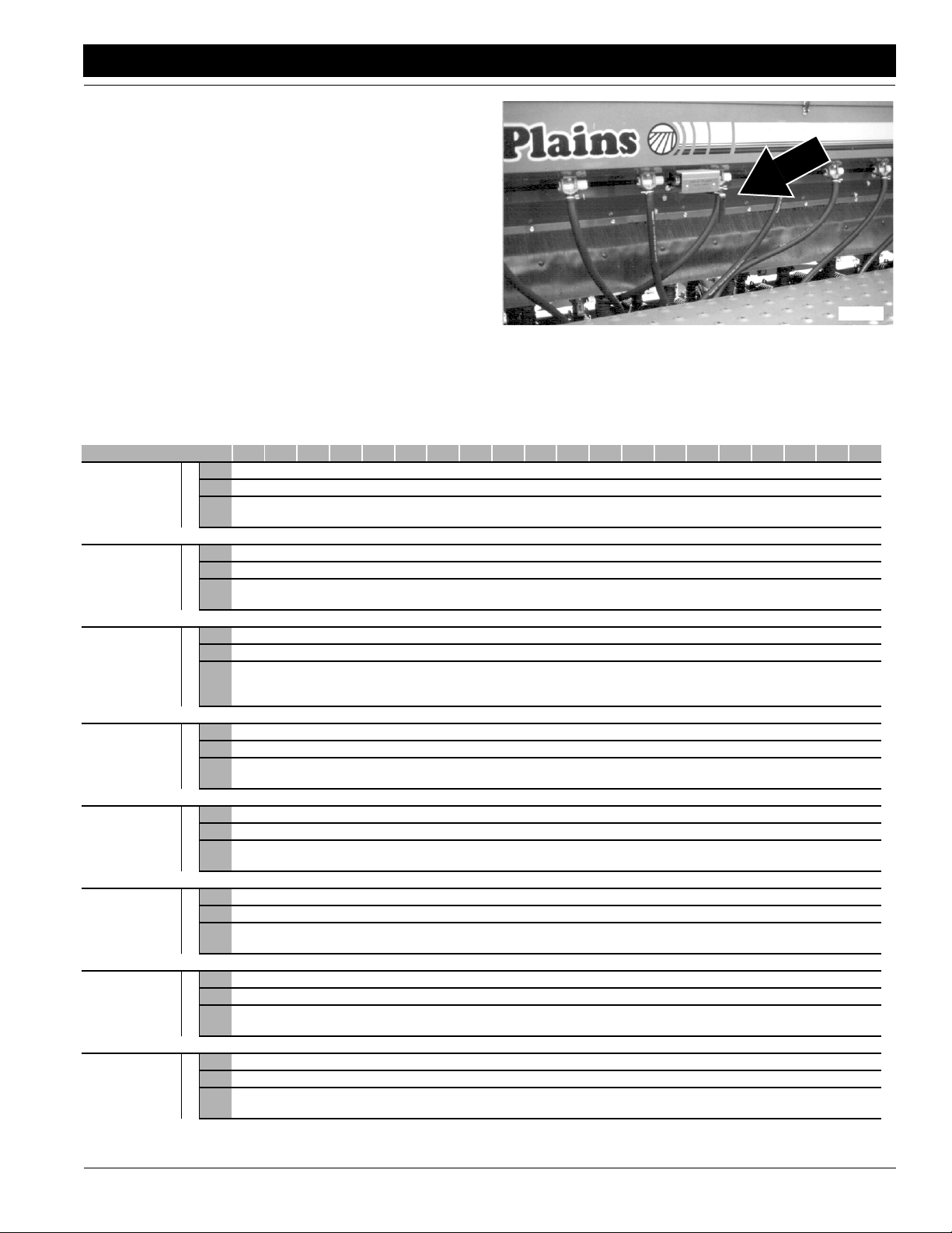
Great Plains Mfg., Inc.
Section 3 Adjustments
Small Seeds Attachment
To set and calibrate the seeding rate on the optional small
seeds attachment, follow these steps.
1. Set the seed-rate handle on the small seeds attachment as indicated by the Small Seeds Rate Chart, this
page. The seed-rate handle for the small seeds attachment is shown in Figure 3-7.
2. Calibrate the small seeds attachment to your material
by following the steps under Check Seeding Rate,
page 24.
Figure 3-7
Small Seeds Rate Handle
Small Seeds Rate Chart (Imperial Measurement)
Setting Number 5 10 15 20 25 30 35 40 45 50 55 60 65 70 75 80 85 90 95 100
Kentucky Blue
Grass, Fescue,
Annual Rye
Grass
6" 0 .2 1.2 1.9 2.7 3.3 4.1 4.6 5.2 5.8 6.3 6.8 7.3 7.8 8.3 8.8 9.2 9.7 10.0 10.5
7.5" 0 .2 .9 1.5 2.2 2.7 3.3 3.7 4.2 4.6 5.1 5.5 5.9 6.3 6.7 7.0 7.4 7.7 8.1 8.4
10" 0 .1 .7 1.1 1.6 2.0 2.4 2.7 3.1 3.4 3.7 4.0 4.3 4.6 4.9 5.2 5.4 5.7 5.9 6.2
Row Spacing
17050
Ladino Clover,
Canary Grass,
Timothy, Canola
Bermuda, Red
Top, Unhulled
Lespedeza, Ser-
cia, Sand &
Weeping Love
Grass
Red & Sweet
Clover, Lespe-
deza Hulled
Bird’s-foot Tre-
foil, Sudan
Orchard Grass
Millet,
Reed Canary
6" 0 1.1 2.1 3.3 4.7 6.1 7.6 9.2 10.7 12.2 13.8 15.5 17.0 18.5 20.3 21.7 23.4 25.4 27.3 29.2
7.5" 0 .9 1.6 2.6 3.9 4.9 6.1 7.4 8.6 9.8 11.1 12.5 13.7 14.9 16.3 17.6 18.8 20.4 21.9 23.5
10" 0 .6 1.5 1.9 2.5 3.6 4.5 5.4 6.3 7.2 8.1 9.1 10.0 10.9 12.0 12.9 13.8 14.9 16.1 17.2
Row Spacing
6" 0 .7 1.1 1.7 2.6 3.3 4.1 5.0 5.9 6.6 7.2 7.8 8.4 9.0 9.5 10.2 10.9 11.6 12.2 12.9
7.5" 0 .5 .9 1.4 2.1 2.6 3.3 4.0 4.7 5.3 5.8 6.3 6.7 7.2 7.6 8.2 8.8 9.3 9.8 10.4
10" 0 .4 .6 1.0 1.5 1.9 2.4 3.0 3.5 3.9 4.2 4.6 4.9 5.3 5.6 6.0 6.4 6.8 7.2 7.6
Row Spacing
6" 0 1.5 3.4 5.2 7.1 9.0 11.3 13.2 15.3 17.0 19.0 20.8 22.5 24.5 26.4 28.3 30.1 32.1 33.8 35.6
7.5" 0 1.2 2.7 4.2 5.7 7.2 9.1 10.6 12.3 13.7 15.3 16.7 18.1 19.7 21.2 22.7 24.2 25.8 27.2 28.6
10" 0 .9 2.0 3.1 4.2 5.3 6.7 7.8 9.0 10.0 11.2 12.2 13.3 14.4 15.6 16.6 17.8 18.9 19.9 20.9
Row Spacing
6" 0 1.7 3.3 5.2 6.8 8.7 10.7 12.7 14.7 16.8 19.2 21.2 23.4 25.6 28.0 29.9 32.1 34.2 36.3 38.4
7.5" 0 1.4 2.6 4.2 5.4 7.0 8.6 10.2 11.9 13.5 15.4 17.0 18.8 20.5 22.5 24.0 25.8 27.6 29.1 30.9
10" 0 1.0 1.9 3.1 4.0 5.1 6.3 7.5 8.6 9.9 11.3 12.5 13.8 15.1 16.5 17.6 18.9 20.2 21.4 22.7
Row Spacing
6" 0 0 .3 ,7 .9 1.3 1.5 2.0 2.4 2.8 3.3 3.5 3.9 4.4 4.8 5.0 5.5 5.7 6.1 6.3
7.5" 0 0 .2 .5 .7 1.1 1.2 1.6 1.9 2.3 2.6 2.8 3.2 3.5 3.9 4.0 4.4 4.6 4.9 5.1
10" 0 0 .1 .4 .5 .8 .9 1.2 1.4 1.7 1.9 2.1 2.3 2.6 2.8 3.0 3.2 3.3 3.6 3.7
Row Spacing
6" .4 1.4 2.4 3.5 4.4 5.5 6.5 7.5 8.5 9.5 10.5 11.5 12.5 13.6 14.6 15.6 16.6 17.6 18.5 19.0
7.5" .3 1.2 2.0 2.8 3.6 4.4 5.2 6.0 6.8 7.6 8.4 9.3 10.1 10.9 11.7 12.5 13.3 14.1 14.9 15.1
10" .3 .8 1.4 2.0 2.6 3.2 3.8 4.4 5.0 5.6 6.2 6.8 7.4 8.0 8.6 9.2 9.8 10.4 10.9 11.5
Row Spacing
Alfalfa, Red
Alsike, Crimson
Clover
9/26/13
6" 0 2.2 3.5 4.8 6.0 7.5 8.7 9.8 11.2 12.5 13.8 15.1 16.4 17.5 18.6 20.2 21.4 22.9 24.0 25.2
7.5" 0 1.8 2.8 3.9 4.8 6.0 7.0 7.9 9.0 10.0 11.1 12.1 13.2 14.0 15.3 16.2 17.2 18.3 19.3 20.3
10" 0 1.3 2.1 2.8 3.5 4.4 5.1 5.8 6.6 7.4 8.1 8.9 9.7 10.3 11.2 11.9 12.6 13.4 14.2 14.9
Row Spacing
2S-2600 and 2S-2600F Two-Section Folding Drill 195-200M-A
31
Page 34

Great Plains Mfg., Inc.
Section 3 Adjustments
Small Seeds Rate Chart (Metric Measurement)
Setting Number 5 10 15 20 25 30 35 40 45 50 55 60 65 70 75 80 85 90 95 100
Kentucky Blue
Grass, Fescue,
Annual Rye
Grass
15.24cm
19.05cm
25.40cm
Row Spacing
0.0 0.2 1.4 2.1 3.0 3.7 4.6 5.2 5.9 6.5 7.1 7.7 8.2 8.8 9.4 9.9 10.4 10.9 11.3 11.8
0.0 0.2 1.0 1.7 2.5 3.0 3.7 4.2 4.7 5.2 5.7 6.2 6.6 7.1 7.5 7.9 8.3 8.7 9.1 9.5
0.0 0.1 0.8 1.2 1.8 2.3 2.7 3.0 3.5 3.8 4.2 4.5 4.8 5.2 5.5 5.9 6.1 6.4 6.6 7.0
Ladino Clover,
Canary Grass,
Timothy, Canola
Bermuda, Red
Top, Unhulled
Lespedeza, Ser-
cia, Sand &
Weeping Love
Grass
Red & Sweet
Clover, Lespe-
deza Hulled
Bird’s-foot Tre-
foil, Sudan
Orchard Grass
Millet,
Reed Canary
15.24cm
19.05cm
25.40cm
Row Spacing
15.24cm
19.05cm
25.40cm
Row Spacing
15.24cm
19.05cm
25.40cm
Row Spacing
15.24cm
19.05cm
25.40cm
Row Spacing
15.24cm
19.05cm
25.40cm
Row Spacing
15.24cm
19.05cm
25.40cm
Row Spacing
0.0 1.2 2.4 3.7 5.3 6.9 8.6 10.4 12.1 13.7 15.5 17.5 19.2 20.7 22.9 24.5 26.4 28.6 30.8 32.9
0.0 1.0 1.8 2.9 4.4 5.5 6.9 8.3 9.7 11.0 12.5 14.1 15.4 16.8 18.4 19.8 21.2 23.0 24.7 26.5
0.0 0.7 1.7 2.1 2.8 4.1 5.1 6.1 7.1 8.1 9.1 10.3 11.3 12.3 13.5 14.5 15.5 16.8 18.1 19.4
0.0 0.8 1.2 1.9 2.9 3.7 4.6 5.6 6.6 7.4 8.1 8.8 9.5 10.1 10.7 11.5 12.3 13.1 13.7 14.5
0.0 0.6 1.0 1.6 2.4 2.9 3.7 4.5 5.3 6.0 6.5 7.1 7.5 8.1 8.6 9.2 9.9 10.5 11.0 11.7
0.0 0.5 0.7 1.1 1.7 2.1 2.7 3.4 3.9 4.4 4.7 5.2 5.5 6.0 6.3 6.8 7.2 7.7 8.1 8.6
0.0 1.7 3.8 5.9 8.0 10.1 12.7 14.9 17.2 19.2 21.4 23.4 25.4 27.6 29.7 31.9 33.9 36.2 38.1 40.1
0.0 1.4 3.0 4.7 6.4 8.1 10.3 11.9 13.9 15.4 17.2 18.8 20.4 22.2 23.9 25.6 27.3 29.1 30.6 32.2
0.0 1.0 2.3 3.5 4.7 6.0 7.5 8.8 10.1 11.3 12.6 13.7 15.0 16.2 17.6 18.7 20.1 21.3 22.4 23.6
0.0 1.9 3.7 5.9 7.7 9.8 12.1 14.3 16.6 18.9 21.6 23.9 26.4 28.8 31.6 33.7 36.2 38.5 40.9 43.3
0.0 1.6 2.9 4.7 6.1 7.9 9.7 11.5 13.4 15.2 17.4 19.2 21.2 23.1 25.4 27.0 29.1 31.1 32.8 34.8
0.0 1.1 2.1 3.5 4.5 5.7 7.1 8.5 9.7 11.2 12.7 14.1 15.5 17.0 18.6 19.8 21.3 22.8 24.1 25.6
0.0 0.0 0.3 0.8 1.0 1.5 1.7 2.3 2.7 3.2 3.7 3.9 4.4 5.0 5.4 5.6 6.2 6.4 6.9 7.1
0.0 0.0 0.2 0.6 0.8 1.2 1.4 1.8 2.1 2.6 2.9 3.2 3.6 3.9 4.4 4.5 5.0 5.2 5.5 5.7
0.0 0.0 0.1 0.5 0.6 0.9 1.0 1.4 1.6 1.9 2.1 2.4 2.6 2.9 3.2 3.4 3.6 3.7 4.1 4.2
0.5 1.6 2.7 3.9 5.0 6.2 7.3 8.5 9.6 10.7 11.8 13.0 14.1 15.3 16.5 17.6 18.7 19.8 20.8 21.4
0.3 1.4 2.3 3.2 4.1 5.0 5.9 6.8 7.7 8.6 9.5 10.5 11.4 12.3 13.2 14.1 15.0 15.9 16.8 17.0
0.3 0.9 1.6 2.3 2.9 3.6 4.3 5.0 5.6 6.3 7.0 7.7 8.3 9.0 9.7 10.4 11.0 11.7 12.3 13.0
Alfalfa, Red
Alsike, Crimson
Clover
2S-2600 and 2S-2600F Two-Section Folding Drill 195-200M-A 9/26/13
32
15.24cm
19.05cm
25.40cm
Row Spacing
0.0 2.5 3.9 5.4 6.8 8.5 9.8 11.0 12.6 14.1 15.5 17.0 18.5 19.7 21.0 22.8 24.1 25.8 27.0 28.4
0.0 2.0 3.2 4.4 5.4 6.8 7.9 8.9 10.1 11.3 12.5 13.6 14.9 15.8 17.2 18.3 19.4 20.6 21.7 22.9
0.0 1.5 2.4 3.2 3.9 5.0 5.7 6.5 7.4 8.3 9.1 10.0 10.9 11.6 12.6 13.4 14.2 15.1 16.0 16.8
Page 35

Great Plains Mfg., Inc.
Section 3 Adjustments
Seeding Depth
The 2S-2600 has double-disk openers with depth-controlling press wheels mounted on floating opener frames. This
system provides accurate depth control and seed placement over uneven terrain. When used with live closed-center tractor hydraulics the drill provides constant opener
down pressure througha wide range ofopener movement.
The following is an introduction to the seeding components and how they work.
Double Disk Openers
Each opener is mounted on a floating opener frame.
Opener bodies are staggered for easy soil flow. Long and
short opener bodies provide for 7" of stagger for planting
through residue. All openers pivot on a common axis to
maintain consistent depth as opener frames follow contours. A single spring provides down pressure necessary
for the double disks to open a seed furrow. The spring allows openers to float down into depressions and up over
obstructions. Individual openers can be adjusted to account for tire tracks. Refer to page 35 for individual opener
adjustment instructions.
Press Wheels
A press wheel is attached to each opener body. Press
wheels provide two important functions.
First, press wheels close seed furrows and gently press
soil over seed. To provide consistent seed firming, press
wheels are free to move down from normal operating position. This maintains pressing action even if opener disks
encounter obstructions or hard soil.
Second, press wheels control seeding depth. To maintain
a consistent depth, the relationship between the bottom of
the opener disks and press wheel is fixed upwardly by an
adjustable stop on each opener. The position of the adjustable stop determines how deep seed is placed. Raising
the stop increases seeding depth. Lowering the stop decreases seeding depth. Refer to page 35 for press wheel
adjustment.
Floating Opener Frames
Each drill section has an opener frame which pivots about
the center line of the drill gauge wheels. These floating
opener frames have the ability to rock the openers 15 degrees up and 15 degrees down as a group. By pivoting at
the gauge wheels, openers maintain a consistent depth as
opener frames rock up and back.
Down pressure for each opener frame is provided by two
cylinders working on a constant lever arm. When combined with live hydraulics, the cylinders provide constant
down pressure across the width of each opener frame –
regardless of how the frame is positioned. Two cylinders
per opener framealong with specialtrunnions alsoprovide
some ability for one end of an opener frame to rock independent of the other while maintaining constant opener
down pressure across the frame. A pressure-control valve
on each circuit allows you to adjust down pressure.
The opener frame has one adjustment point for two different operating positions – one for drilling with normal down
pressure and another for drilling with high down pressure.
Refer to Opener Frame Adjustment, page 35.
00 Series Opener Down Pressure
Crushing hazard – You will be seriously injured or killed if you are
caught between raising openers and drill frame. Always stop tractor
engine, set park bake, and remove key before adjusting or servicing
openers. Keep all bystanders well away during drill operation.
Escaping fluid under pressure can penetrate the skin causing serious
injury. Avoid the hazard by relieving pressure before disconnecting
hydraulic lines. Use a piece of paper or cardboard, NOT BODY
PARTS, to check for suspected leaks. Wear protective gloves and
safety glasses or goggles when working with hydraulicsystems. If an
accident occurs, see a doctorimmediately.Any fluid injected into the
skin must be surgically removed within a few hours or gangrene may
result.
Opener down pressure controls opener penetration and
press-wheel soil firming. Use only enough down pressure to
cut a furrow and maintain proper soil-firming over seed. Excessive opener down force may cause bulldozing of the openers in light soil conditions, and will lead to premature wear on
opener components.
The following chart shows the approximate force at the openers for a given pressure at the pressure control valve.
Gauge
Setting
200 PSI 83 86 92
300 PSI 90 95 102
400 PSI 97 103 113
500 PSI 103 111 124
600 PSI 110 119 135
700 PSI 117 128 146
800 PSI 123 136 157
900 PSI 130 144 167
1000 PSI 137 152 178
1100 PSI 143 161 189
1200 PSI 150 169 200
1300 PSI 157 177 211
1400 PSI 163 185 222
1500 PSI 170 194 233
1600 PSI 176 202 244
1700 PSI 183 210 254
1800 PSI 190 218 264
NOTE: To account for additional compaction from drill and
tractor tires, set pressure on inside openers slightly higher
than outside openers.
Pounds Force at Opener Disks
6 inch rows 7 1/2 inch rows 10 inch rows
9/26/13
2S-2600 and 2S-2600F Two-Section Folding Drill 195-200M-A
33
Page 36

Section 3 Adjustments
Great Plains Mfg., Inc.
Active Hydraulic System
3. Once pressure is set, lock knob with lock disk.
To run the drill with constant opener down pressure requires an Active Hydraulic System. An Active Hydraulic
System requires a tractor with closed-center hydraulics or
pressure/flow compensated hydraulics powered by a variable displacement hydraulic pump. (If you are not familiar
with your tractor's hydraulics, consult your tractor dealer.)
IMPORTANT: Tractors with load-sensing hydraulics
must use the bypass valve to operate the 2600-3S. Failure to use the bypass valve can cause major tractor
damage. Before adjusting opener down pressure, set
bypass valve as explained under Setting the Bypass
Valve, page 16.
NOTE: To run the drill on tractors with open-center hydraulics or on tractors with fixed displacement hydraulic pumps
you must install a Great Plains kit, part number 194-143A.
Contact your Great Plains dealer for ordering information.
Refer to Non-Active Hydraulics System on this page.
To set down pressure:
1. Lower openers to the ground. Lock hydraulic lever for-
ward for constant hydraulic flow.
John Deere tractors with Sound-Gard ® Body: Use
lever lock clip, John Deere part number R52667, to
lock lever forward. See your tractor dealer for clip purchase and installation.
John Deere 7000 Series tractors: Rotate valve
detent selector to motor position to lock lever in forward position.
John Deere 8000 Series tractors: Set timer to con-
tinuous. Push lever forward until detent clicks.
Case-IH Magnum tractors: Lock lever forward in
detent position. You may need to turn up detent pressure to its maximum setting. Do not tie hydraulic lever
past detent position with a strap. See your tractor
dealer for hydraulic-system details.
Other tractors: Lock lever forward in detent position.
You may need to turn up detent pressure to maximum
or use a mechanical detent holder to hold lever forward. See your tractor dealer for proper means of providing constant flow to openers.
2. Turn knob on pressure-control valve, see Figure 3-8.
While watching pressure gauge, turn knob until gauge
shows desired pressure. Turn clockwise to increase
pressure. Turn counterclockwise to decrease pressure.
There is one pressure-control valve for openerson the
inside of drill and one for openers on the outside ends.
As a general starting point, set hydraulic down pressure to 800 psi. For most field conditions, adjust down
pressure between 200 and 1400 psi. Setting the opener down pressure above 1600 psi. will raise the drive
wheels off the ground when the seed box is empty
Pressure Control Valves
Non-Active Hydraulic System
To run the drill on tractors with open-center hydraulics or
on tractors with fixed displacement hydraulic pumps requires a kit (Great Plains part number194-143A). This kit
utilizes a non-active hydraulic system which allows you to
pressurize your openers down and lock inthat pressure on
level ground by holding the opener frames in a fixed position.
To set down pressure:
1. Lower opener frames by pushing forward on tractor
hydraulic lever. Lock lever temporarily in this position
while adjusting opener down pressure.
2. Turn knob on pressure-control valve, see Figure 3-8.
While watching pressure gauge, turn knob until gauge
shows desired pressure. Turn clockwise to increase
pressure. Turn counterclockwise to decrease pressure.
There is one pressure-control valve for openerson the
inside of drill and one for openers on the outside ends.
As a general starting point, set hydraulic down pressure to 800 psi. For most field conditions, adjust down
pressure between 200 and 1400 psi. Setting the opener down pressure above 1600 psi. will raise the drive
wheels off the ground when the seed box is empty
causing skips and poor seed metering. Refer to the
chart on page 33 for approximate force at the openers
for a given pressure setting.
3. Once pressure is set, lock knob with lock disk.
Figure 3-8
causing skips and poor seed metering. Refer to the
chart on the previous page for approximate force at
the openers for a given pressure setting.
2S-2600 and 2S-2600F Two-Section Folding Drill 195-200M-A 9/26/13
34
15557
Page 37
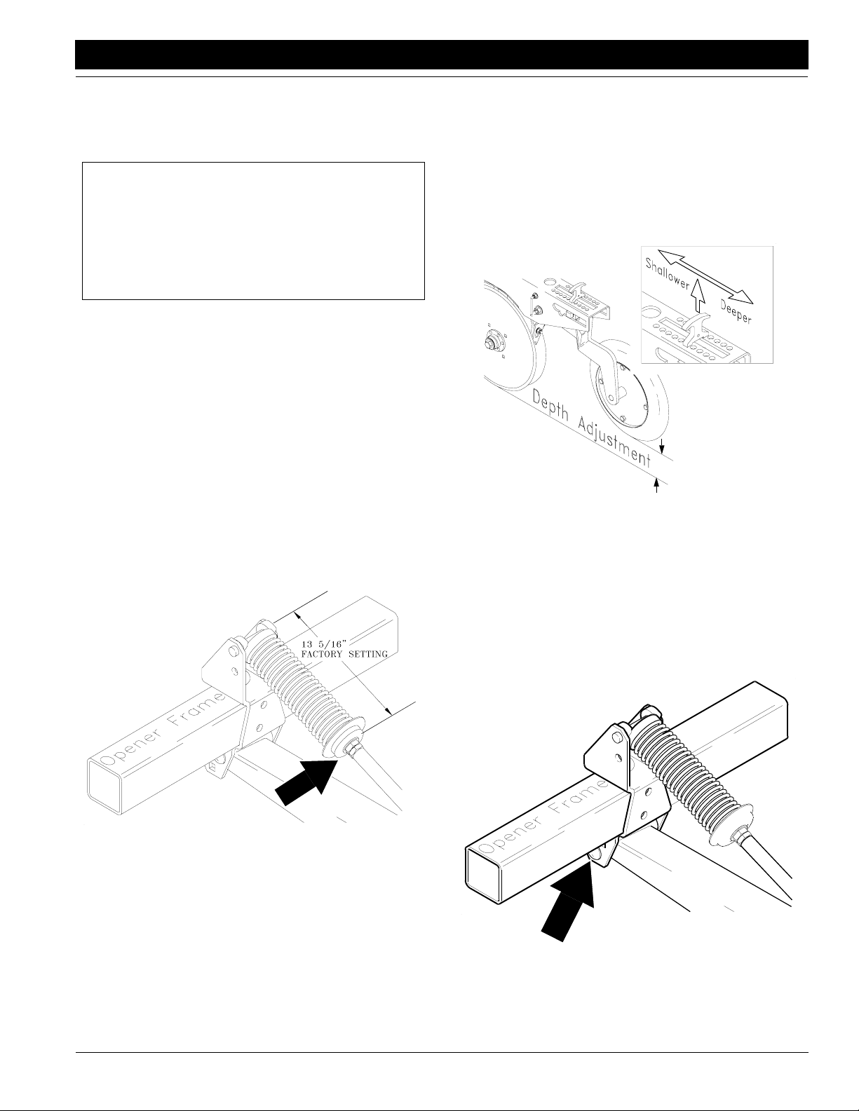
Great Plains Mfg., Inc.
Section 3 Adjustments
4. After opener down pressure is set, return tractor hydraulic lever to neutral. This locks in the selected pressure, and opener frames will remain fixed in this
position.
IMPORTANT: Open-center tractors and tractors with
fixed-displacement pumps are not designed to provide
a continuous supply of pressurized oil to remote valves.
Locking hydraulic lever forward on these tractors can
cause overheating of hydraulic oil and tractor damage.
After setting opener down pressure, always return hydraulic lever to neutral.
NOTE: On some tractors with very positive remote hydraulic checks, a slight increase in the reading on the pressure
gauges may occur after the tractor remote lever is returned to neutral. This is caused by back pressure on the
opener cylinders and should be ignored. The NET OPERATING PRESSURE on the opener cylinders is maintained
at the pressure you selected while the tractor remote lever
was held forward, not at the "apparently increased" pressure. Reactivating the tractor lever forward will confirm
this.
Spring Down Pressure – Individual Openers
For planting in tire tracks, you can increase spring pressure
on individual openers. To increase spring pressure, tighten
flange nut at lower end of opener spring. See Figure 3-9.
Each 1/4-inch adjustment adds about 13 pounds of force at
opener disk. Do not tighten nut more than one inch. After
adjusting, lock flange nut in place with jam nut.
00 Series Opener Depth
Press Wheel Adjustment
Set opener seeding depth by adjusting press-wheel
height. To adjust, first raise openers slightly, then lift and
slide T-handles on top of openers as shown in Figure 3-10.
Adjust all press wheels to the same height.
• For shallower seeding, slide T handles toward drill.
• For deeper seeding, slide T handles away from drill.
Figure 3-10
Press Wheel Adjustment
NOTE: Opener down pressure controls soil-firming pressure on press wheel. Use press-wheel adjustments to regulate seeding depth and opener-down-pressure
adjustments to control opener penetration andsoil firming.
Individual Opener Height
You may need to lower an opener which runs in a tire track.
To lower individual openers, move opener-pivot bolt to
lower hole in opener mount. See Figure 3-11.
15659
9/26/13
Figure 3-9
Individual Opener Pressure Adjustment
15637
15671
Figure 3-11
Individual Opener Height
2S-2600 and 2S-2600F Two-Section Folding Drill 195-200M-A
35
Page 38

Section 3 Adjustments
Great Plains Mfg., Inc.
00 Series Opener Frame Adjustment
You can adjust opener frames between two operating
positions–one for normal down pressure and one for higher down pressure. The adjustment is near the openerframe pivots. See Figure 3-12. There are three holes and
two bolts. The bottom bolt (1) serves as the pivot. The top
bolt (2) is for adjustment.
For normal drilling conditions, keep top bolt in second hole
as shown in Figure 3-12. Use this setting when drilling with
opener down pressure below 1600 psi.
When drilling with opener down pressure above 1600 psi,
place top bolt in top hole on all four pivot points across drill.
2
1
15558
Figure 3-12
Opener Frame Adjustment
00 Series Seed-Lok Lock Up
Optional Seed-Lok firming wheels provide additional
seed-to-soil contact. The wheels are spring loaded and do
not require adjusting. In some wet and sticky conditions
the wheels may accumulate soil.
To lock up firming wheels, refer to Figure 3-14. Hook one
end of chain in opener-body hole just above wheel arm
(1). Pull firming-wheel arm (2) up as high as possible and
wrap chain around arm. Hook other end of chain in a link.
Leave no slack in chain; secure wheel arm in its highest
position.
1
2
16856
Figure 3-14
Seed-Lok Lock Up
00 Series Disk Scraper Adjustment
To keep opener disks turning freely, dirt scrapers are
mounted between disks to clean as the disks rotate. As
field conditions vary, you may need to adjust scrapers. In
damp conditions, lower scrapers. If openers are not turning freely, raise scrapers.
To adjust, loosen 3/8-inch bolt shown in Figure 3-13 and
move scraper as needed.
16163
Figure 3-13
Disk Scraper Adjustment
Crushing hazard – You will be seriously injured or killed if you
are caught between raising openers and drill frame. Always
stop tractor engine, set park bake, and remove key before adjusting or servicing openers. Keep all bystanders well away
during drill operation.
Escaping fluid under pressure can penetrate the skin causing
serious injury. Avoid the hazard by relieving pressure before
disconnecting hydraulic lines. Use a piece of paper or cardboard, NOT BODY PARTS, to check for suspected leaks. Wear
protective gloves and safety glasses or goggles when working
with hydraulic systems. If an accident occurs, see a doctor immediately. Any fluid injected into the skin must be surgically removed within a few hours or gangrene may result.
Opener down pressure controls opener penetration and
press-wheel soil firming. Use only enough down pressure
to cut a furrow and maintain proper soil-firming over seed.
Excessive opener down force may cause bulldozing of the
openers in light soil conditions, and will lead to premature
wear on opener components.
2S-2600 and 2S-2600F Two-Section Folding Drill 195-200M-A 9/26/13
36
Page 39

Great Plains Mfg., Inc.
Section 3 Adjustments
The following chart shows the approximate force at the
openers for a given pressure at the pressure control valve.
Gauge
Setting
200 PSI 130 135 144
300 PSI 136 144 155
400 PSI 143 152 167
500 PSI 148 160 179
600 PSI 154 167 189
700 PSI 157 172 196
800 PSI 161 178 205
900 PSI 166 184 213
1000 PSI 171 190 223
1100 PSI 172 194 228
1200 PSI 180 203 240
1300 PSI 184 208 248
1400 PSI 189 215 258
1500 PSI 193 220 264
1600 PSI 198 227 274
1700 PSI 202 232 281
1800 PSI 209 240 291
Pounds Force at Opener Disks
6 inch rows 7 1/2 inch rows 10 inch rows
NOTE: To account for additional compaction from drill and
tractor tires, set pressure on inside openers slightly higher
than outside openers.
Active Hydraulic System
To run the drill with constant opener down pressure requires an Active Hydraulic System. An Active Hydraulic
System requires a tractor with closed-center hydraulics or
pressure/flow compensated hydraulics powered by a variable displacement hydraulic pump. (If you are not familiar
with your tractor's hydraulics, consult your tractor dealer.)
IMPORTANT: Tractors with load-sensing hydraulics
must use the bypass valve to operate the 2600-3S. Failure to use the bypass valve can cause major tractor
damage. Before adjusting opener down pressure, set
bypass valve as explained under Setting the Bypass
Valve, page 16.
NOTE: To run the drill on tractors with open-center hydraulics or on tractors with fixed displacement hydraulic pumps
you must install a Great Plains kit, part number 194-143A.
Contact your Great Plains dealer for ordering information.
Refer to Non-Active Hydraulics System on this page.
To set down pressure:
1. Lower openers to the ground. Lock hydraulic lever forward for constant hydraulic flow.
John Deere tractors with Sound-Gard ® Body: Use
lever lock clip, John Deere part number R52667, to
lock lever forward. See your tractor dealer for clip purchase and installation.
John Deere 7000 Series tractors: Rotate valve
detent selector to motor position to lock lever in forward position.
John Deere 8000 Series tractors: Set timer to con-
tinuous. Push lever forward until detent clicks.
Case-IH Magnum tractors: Lock lever forward in
detent position. You may need to turn up detent pressure to its maximum setting. Do not tie hydraulic lever
past detent position with a strap. See your tractor
dealer for hydraulic-system details.
Other tractors: Lock lever forward in detent position.
You may need to turn up detent pressure to maximum
or use a mechanical detent holder to hold lever forward. See your tractor dealer for proper means of providing constant flow to openers.
2. Turn knob on pressure-control valve, see Figure 3-15.
While watching pressure gauge, turn knob until gauge
shows desired pressure. Turn clockwise to increase
pressure. Turn counterclockwise to decrease pressure.
There is one pressure-control valve for openers on the
inside of drill and one for openers on the outside ends.
As a general starting point, set hydraulic down pressure to 800 psi. For most field conditions, adjust down
pressure between 200 and 1400 psi. Setting the opener down pressure above 1700 psi. will raise the drive
wheels off the ground when the seed box is empty
causing skips and poor seed metering. Refer to the
9/26/13
2S-2600 and 2S-2600F Two-Section Folding Drill 195-200M-A
37
Page 40
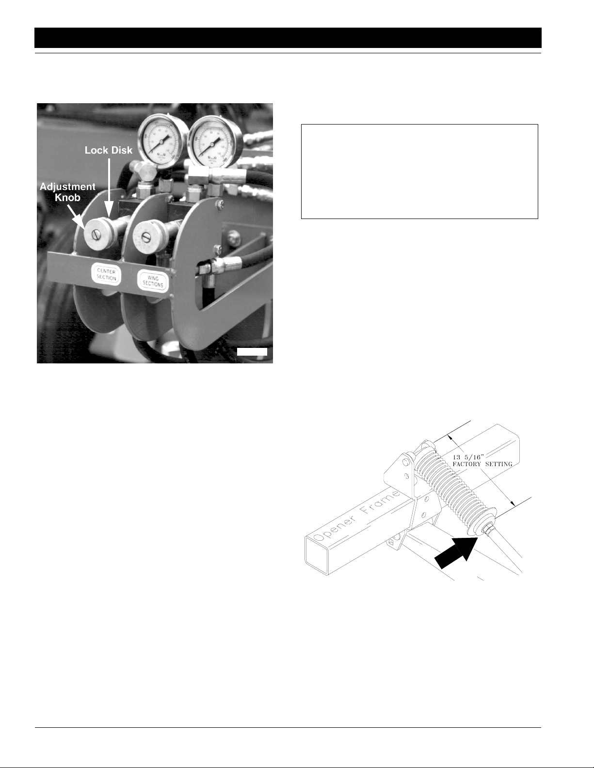
Section 3 Adjustments
Great Plains Mfg., Inc.
chart on the previous page for approximate force at
the openers for a given pressure setting.
3. Once pressure is set, lock knob with lock disk.
15557
Figure 3-15
Pressure Control Valves
Non-Active Hydraulic System
To run the drill on tractors with open-center hydraulics or
on tractors with fixed displacement hydraulic pumps requires a kit (Great Plains part number194-143A). This kit
utilizes a non-active hydraulic system which allows you to
pressurize your openers down and lock inthat pressure on
level ground by holding the opener frames in a fixed position.
To set down pressure:
1. Lower opener frames by pushing forward on tractor
hydraulic lever. Lock lever temporarily in this position
while adjusting opener down pressure.
2. Turn knob on pressure-control valve, see Figure 3-8.
While watching pressure gauge, turn knob until gauge
shows desired pressure. Turn clockwise to increase
pressure. Turn counterclockwise to decrease pressure.
There is one pressure-control valve for openerson the
inside of drill and one for openers on the outside ends.
As a general starting point, set hydraulic down pressure to 800 psi. For most field conditions, adjust down
pressure between 200 and 1400 psi. Setting the opener down pressure above 1700 psi. will raise the drive
wheels off the ground when the seed box is empty
causing skips and poor seed metering. Refer to the
chart on page 33 for approximate force at the openers
for a given pressure setting.
3. Once pressure is set, lock knob with lock disk.
4. After opener down pressure is set, return tractor hydraulic lever to neutral. This locks in the selected pressure, and opener frames will remain fixed in this
position.
IMPORTANT: Open-center tractors and tractors with
fixed-displacement pumps are not designed to provide
a continuous supply of pressurized oil to remote valves.
Locking hydraulic lever forward on these tractors can
cause overheating of hydraulic oil and tractor damage.
After setting opener down pressure, always return hydraulic lever to neutral.
NOTE: On some tractors with very positive remote hydraulic checks, a slight increase in the reading on the pressure
gauges may occur after the tractor remote lever is returned to neutral. This is caused by back pressure on the
opener cylinders and should be ignored. The NET OPERATING PRESSURE on the opener cylinders is maintained
at the pressure you selected while the tractor remote lever
was held forward, not at the "apparently increased" pressure. Reactivating the tractor lever forward will confirm
this.
Spring Down Pressure – Individual Openers
For planting in tire tracks, you can increase spring pressure
on individual openers. To increase spring pressure, tighten
flange nut at lower end of opener spring. See Figure 3-16.
Each 1/4-inch adjustment adds about 13 pounds of force at
opener disk. Do not tighten nut more than one inch. After
adjusting, lock flange nut in place with jam nut.
15637
Figure 3-16
Individual Opener Pressure Adjustment
2S-2600 and 2S-2600F Two-Section Folding Drill 195-200M-A 9/26/13
38
Page 41

Great Plains Mfg., Inc.
Section 3 Adjustments
Marker Adjustments
Speed Adjustment
Adjust folding speed for dual markers with hex adjustment
screws on the sequence-valve body as shown in Figure 3-
17. There is one adjustment screw for raising speed (1)
and one for lowering speed (2). You can identify adjustment screws by markings stamped in valve body.
Turn adjustment screws clockwise to decrease folding
speed and counterclockwise to increase folding speed.
With tractor idling at a normal operating speed, adjust
marker folding to a safe speed. Excessive folding speed
could damage markers and void the warranty.
After adjusting the folding speed, tighten jam nuts on hex
adjustment screws to hold settings.
14048
Transport Carrier
When marker is folded, the second section should be centered in transport-carrier saddle and parallel with top of
drill box.
To adjust front-to-rear position of saddle, loosen 1/2-by-6inch u-bolts (1) that fasten transport-carrier mount onto
box frame. Slide transport-carrier assembly forward or
back as needed.
To adjust height of saddle, loosen 1/2-by-2-inch u-bolts (2)
that hold carrier tube to mounting bracket. Slide carrier
tube up or down as needed. Refer to Figure 3-19.
Figure 3-17
Speed Adjustment, Dual Markers
The hydraulic system for a single marker has a needle
valve to control folding speed. The needle valve is in the
hydraulic hose at rod end of marker cylinder as shown in
Figure 3-18.
Turn adjustment knob clockwise to reduce folding speed
or counterclockwise to increase folding speed.With tractor
idling at a normal operating speed, adjust marker folding
to a safe speed. Excessive folding speed could damage
markers and void the warranty.
Needle Valve
15632
Figure 3-19
Marker Transport Carrier Adjustment
15625
9/26/13
Figure 3-18
Single Marker Speed Adjustment
2S-2600 and 2S-2600F Two-Section Folding Drill 195-200M-A
39
Page 42
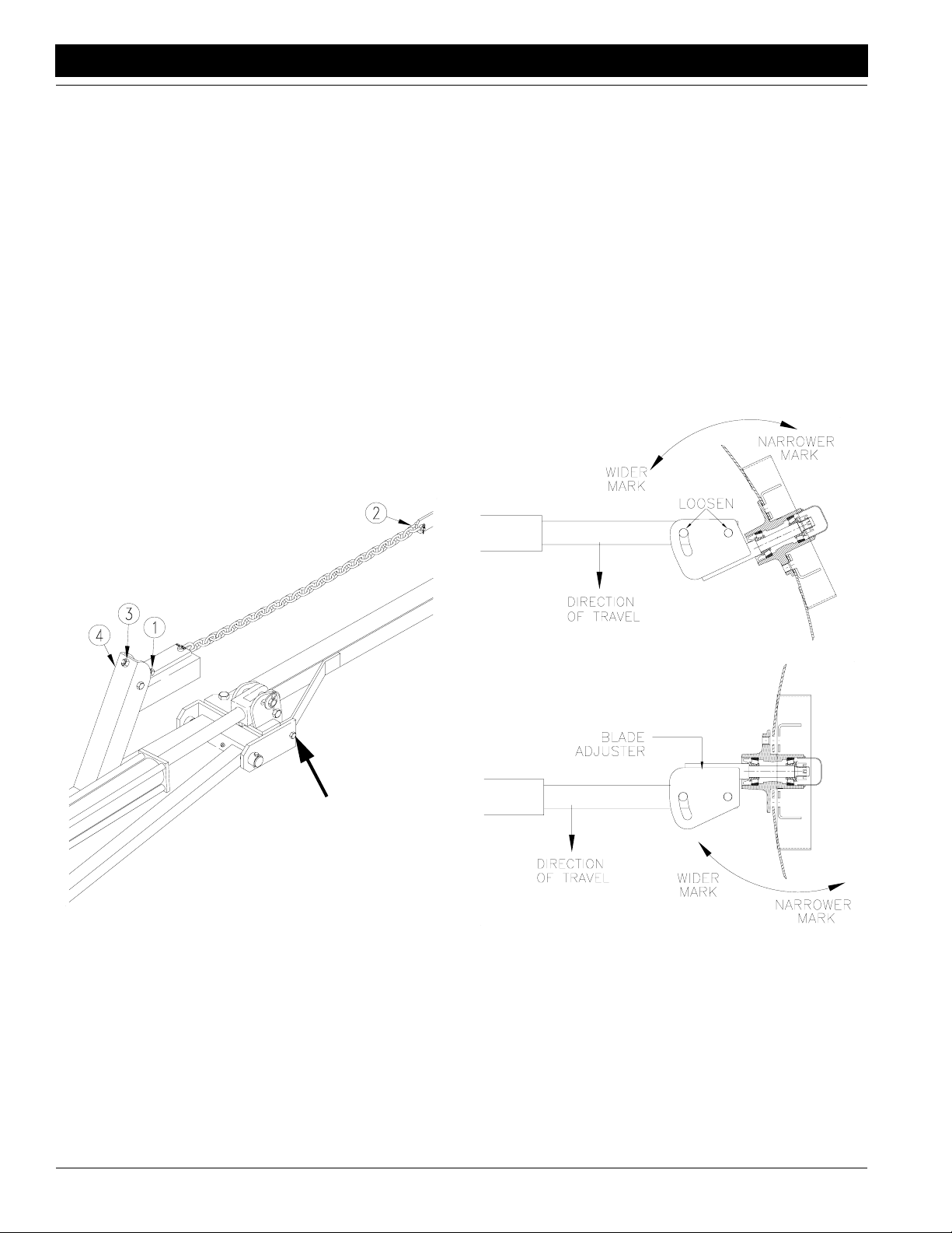
Section 3 Adjustments
Great Plains Mfg., Inc.
Marker Chain
There are two, interrelated adjustments for the marker
chain. Make these adjustments in the following order. Refer to Figure 3-20.
1. Lifting Slack. With marker unfolded, back full-threaded adjustment bolt (1) down until head extends as little
as possible. Slowlyfold marker while observing disk. If
marker disk slides across ground more than a foot before chain and linkage lifts it up, the chain is too long.
Shorten chain one or two links by moving clevis (2).
Check adjustment by repeating folding process.
If chain is too short when marker is unfolded, it will
prevent end of marker from dropping into field depressions, causing skips in your marker line. Correct this
condition by lengthening chain one or two links at clevis (2).
2. Folding Slack. Fold marker. Use full-threaded adjust-
ment bolt (1) to take slack out of chain while marker is
folded. Extend bolt until there is no chain slack. Lock
bolt in this position by tightening nuts (3) on either side
of upright channel (4).
Disk Adjustment
There are two ways you can change the mark left by the
marker disk. Refer to Figure 3-21.
1. Disk Angle. To change angle of cut, loosen 1/2-inch
bolts holding disk assembly. Rotate disk assembly as
desired.
2. Direction of Cut. To change direction of cut and throw
dirt either in or out:
a. Reverse blade and depth band by remounting lug
bolts on disk hub.
b. Reverse angle of assembly by removing two 1/2-
inch bolts holding disk assembly. Turn disk assembly one-half turn. Reinstall 1/2-inch bolts and
set disk angle.
Shear Bolt
Figure 3-20
Marker Chain Adjustment
11757
15669
11248
Figure 3-21
Disk Blade Adjustments
2S-2600 and 2S-2600F Two-Section Folding Drill 195-200M-A 9/26/13
40
Page 43

Great Plains Mfg., Inc.
Section 3 Adjustments
Seed and Fertilizer Capacity
The 2S-2600F is equipped with standard dividers that partition the drill boxes into 60 percent seed and 40 percent
fertilizer. This ratio is suitable for most applications.
If you need more seed or fertilizer capacity, optional offset
dividers allow you to change the ratio. For ordering information, refer to Offset Box Divider,“Options,” page 58. To
install or remove the dividers, refer to Figure 3-22.
Figure 3-22
Box Divider Removal
Drill Box Capacity Ratios
Capacity Ratio Capacity Per Foot Total Capacity
Seed Fertiliz-erSeed Fertilizer Seed Fertilizer
Standard
Divider
Offset
Divider
60% 40% 2 bu. 1.57 Ft351.84 bu. 34.56 bu.
68% 32% 2.2 bu. 1.29 Ft358.76 bu. 27.64 bu.
55% 45% 1.8 bu. 1.83 Ft347.52 bu. 38.88 bu.
27.78
22.20
31.24
3
Ft
3
Ft
3
Ft
1. Remove 5/16-inch bolts (1) and flange nuts (2) from
tabs (3) at each end of drill box.
2. Remove 5/16-inch bolts (4) and nuts (5) from lid-hinge
brackets (6).
3. Loosen but do not remove 1/4-inch bolts (7) and nuts
that clamp lid assembly (8) angle irons to plastic dividers (9).
4. Lift lid assembly (8) out of drill box. Lift dividers (9) out
of drill box. Reinstall standard or offset dividers. Figure 3-23 shows proper positioning for dividers to
achieve different ratios.
5. Reinstall lid assembly by reversing steps 1, 2 and 3.
16372
68%
Seed
16356
60%
Seed
32%
Fertili-
zer
40%
Fertilizer
55%
Seed
Figure 3-23
Seed-to-Fertilizer Ratios
45%
Fertilizer
9/26/13
2S-2600 and 2S-2600F Two-Section Folding Drill 195-200M-A
41
Page 44

Section 3 Adjustments
Great Plains Mfg., Inc.
Frame Adjustments
Eyebolt Adjustment
Before using drill, check that opener frames are level
across drill. When fully raised, top of opener mounts (1)
should clear bottom of drill frame tube by at least 1/2 inch.
To adjust opener frames so all openers have same clearance, loosen jam nut (2) on opener-lift cylinders and turn
adjustment nut. See Figure 3-24. When openers are at
correct height, retighten jam nut. Repeat at each openerlift cylinder if necessary.
2
1
17308
Toolbar Height
Toolbar height is factory set and normally will not require
adjustment. If you tear down the drill for repair or if the toolbar is visibly not level, spacer washers on vertical pivot
pins allow for a small amount of toolbar-height adjustment.
To check toolbar height, park drill on a level surface. Measure from ground to horizontal pivot pin. See Figure 3-26.
If dimension on either side of drill varies more than 1/4
inch, adjust toolbar height.
To adjust toolbar height, repositions spacer washers (1).
See Figure 3-26. First lower openers and set enough
opener down pressure to help balance frame. Raise toolbar by removing spacer washers from top of the vertical
pivot and placing them on bottom side of pivot. Lower toolbar by removing spacer washers from bottom of vertical
pivot and placing them on top of pivot.
1
Figure 3-24
Eyebolt Adjustment for Opener Frame Height
Link Tube
The link tube shown in Figure 3-25 controls folding height
of outer end of drill box. If a drill box does not catch in folding latch when folding, adjust link length to lower or raise
end of box.
1. Unfold and lower drill.
2. Pull upper pin from link clevis (1).
3. Unlock jam nut (2).
4. Thread clevis in or out to lengthen or shorten link.
5. Replace pin and tighten nut.
2
1
17306
Figure 3-26
Toolbar Height Adjustment
17307
Figure 3-25
Adjustment Link
2S-2600 and 2S-2600F Two-Section Folding Drill 195-200M-A 9/26/13
42
Page 45
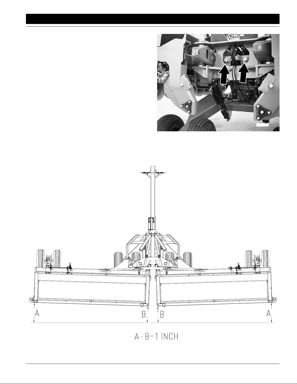
Great Plains Mfg., Inc.
Section 3 Adjustments
Box Alignment
To check and adjust box alignment:
1. Place a block ahead of each wing gauge wheel. Pull
drill forward against blocks to rock frames back. Pull
forward until stop bolts are firmly against toolbars. Refer to Figure 3-27 for stop-bolt location.
2. Check for proper alignment by running a string line
across back of drill toward outer ends of wings. For
proper alignment, outside ends of boxes should be
about 1 inch ahead of inside ends. See Figure 3-28.
3. To adjust box alignment, shorten or lengthen stop
bolts to change the contact point with the toolbars. Adjust stop bolts in or out until outside ends of the boxes
are 1 inch ahead of inside ends.
17357
Figure 3-27
Stop Bolt Location
9/26/13
Figure 3-28
Wing Box Alignment
2S-2600 and 2S-2600F Two-Section Folding Drill 195-200M-A
17300
43
Page 46

Section 4 Troubleshooting
Section 4 Troubleshooting
Problem Solution
Great Plains Mfg., Inc.
Uneven seed spacing or uneven
stand
Opener disks not turning freely
Check for plugging in seed cup.
Check if seed tubes are plugged.
Reduce ground speed.
Check that opener disks turn freely.
Use a faster drive type and close seed-cup doors to narrower position.
Check if openers have enough down pressure to penetrate soil. Increase hydraulic down pressure on openers if necessary. Refer to Opener Down Pressure,
“Adjustments,” page 33.
Check for trash or mud build-up on Seed-Lok wheels. Lock up if necessary. Refer
to Seed-Lok Lock Up, “Adjustments,” page 36.
Check if hydraulic down pressure on openers is too high, causing gauge wheels
to loose contact with ground. Decrease hydraulic down pressure if necessary.
Refer to Opener Down Pressure, “Adjustments,” page 33.
Check for trash or mud build-up on disk scrapers. Readjust scrapers if necessary.
Refer to Disk Scraper Adjustment, “Adjustments,” page 36.
Check if scrapers are adjusted too tight, restricting disk movement. Readjust
scrapers if necessary. Refer to Disk Scraper Adjustment, “Adjustments,” page 36.
Check disk bearings.
Check opener frame for possible damage.
If opener disks turn freely by hand but not in field, reduce hydraulic down pressure. Refer to Opener Down Pressure, “Adjustments,” page 33.
Actual seeding rate
is different than desired
Excessive seed cracking
Acremeter doesn’t measure accurately
Uneven seeding depth
Chain-debris/retainer clip
Check press-wheel adjustment for seeding depth. Refer to Opener Depth,
“Adjustments,” page 35.
Check tire pressure. Refer to Tire Inflation Chart, “Appendix,” page 60.
Check wing gauge wheels. Proper size is 9.5L-15 6-ply.
Check for build-up of seed treatment. Regularly clean off build-up.
Check seed-rate setting. Refer to Seed Rate Calibration, “Adjustments,” page 23.
Consider your seed weight. Seed-rate charts are based on average seed weights.
Use slower drive type and open seed-cup doors to a wider position.
Check tire pressure. Proper inflation is listed on Tire Inflation Chart, “Appendix,”
page 60.
Check gauge-wheel tires. Proper size is 9.5L-15, 6-ply.
Check planting operation for excessive overlap or gaps between passes.
Consider soil conditions. Loose soil and slippage will cause variations in acres
registered.
Check that your acremeter is for your drill. Refer to the 2S-2600 parts manual.
Refer to Opener Depth, “Adjustments,” page 35.
Check that drill tongue matches tractor-drawbar height. Refer to Tractor Hookup,
“Drill Preparation and Setup,” page 9.
Be sure retainer clip is facing opposite way of chain travel.
Press wheel not
compacting the soil as desired
2S-2600 and 2S-2600F Two-Section Folding Drill 195-200M-A 9/26/13
44
Reset press-wheel depth. Refer to Opener Depth, “Adjustments,” page 35.
Increase hydraulic down pressure. Refer to Opener Down Pressure, “Adjustments,” page 33.
Page 47

Great Plains Mfg., Inc.
Section 4 Troubleshooting
Problem Solution
Grain box not emptying evenly
Press wheel or openers plugging
Seed-cup sprockets locked
up or seed-drive shaft twisted
Openers drill too deep
(Bulldozing)
Front of openers dropping too low
in hard or minimum-till conditions
Certain models do not have the same number of seed cups between each bulkhead divider. The section with more seed cups will empty sooner.
Check that you have the same drive type set on both drill boxes.
Consider soil conditions. Drilling in damp or wet conditions can increase this
problem.
Reduce hydraulic down pressure. Refer to Opener Down Pressure, “Adjustments,” page 33.
Do not back up or allow drill to roll backward with openers in ground.
Check Seed-Lok wheels for mud accumulation. Lock up wheels if necessary.
Refer to Seed-Lok Lock Up “Adjustments,” page 36.
Check for foreign material lodged in seed-cup sprockets.
Check for build-up of dried liquid insecticide in seed cups. Remove the build up
by disassembling each seed cup and scraping the foreign substance from the
turning surfaces.
Reduce hydraulic down pressure on openers. Refer to Opener Down Pressure,
“Adjustments,” page 33.
Check press-wheel adjustment. Refer to Opener Depth, “Adjustments,” page 35.
Set opener-frame bolt in top hole. See Opener Frame Adjustments, “Adjustments,” page 35.
Reduce hydraulic down pressure on openers. Refer to Opener Down Pressure,
“Adjustments,” page 33.
Openers raise when tractor
hydraulic lever is held forward and
lower when lever is held back
Opener frames do not float over
uneven terrain
Pressure gauges read zero when
openers are lowered and tractor
hydraulic lever is held forward
Pressure gauges show pressure
when the openers are raised
Transport lock channels will not
stay in position for transport
Optional hydraulic marker functioning
improperly
Optional marker disk does not
mark
Reverse hydraulic hoses at tractor quick couplers.
Check that hydraulic lever is locked forward and openers are connected to circuit
designed for hydraulic-motor control. See Opener Operation, “Operating Instructions,” page 18.
Check if hoses are routed incorrectly between pressure-control valves and
opener-lift cylinders. See hose-routing diagrams under Bleeding the Hydraulics,
“Drill Preparation and Setup,” page 11.
Check if hoses are routed incorrectly between pressure-control valve and openerlift cylinders. See hose-routing diagrams under Bleeding the Hydraulics, “Drill
Preparation and Setup,” page 11.
Check u-shaped clip in lock channel. Clip must clasp cylinder rod securely. If necessary, tighten or loosen clip by turning the bolt on clip.
Before transporting, check that hydraulic cylinders have settled against lock
channels. The weight of cylinders help hold lock channels in place.
Check all hose fittings and connections for air and oil leaks.
Check tractor hydraulic oil level.
Check all bolts and fasteners.
If needle valve is plugged, open valve, cycle markers and reset the needle valve.
If blade does not drop down into field depressions, make sure marker cylinder is
fully extended. Refer to Marker Adjustments, “Adjustments,” page 39.
Reverse blade to pull dirt in or throw dirt out depending on soil conditions.
9/26/13
2S-2600 and 2S-2600F Two-Section Folding Drill 195-200M-A
45
Page 48

Section 5 Maintenance and Lubrication
Section 5 Maintenance and Lubrication
Great Plains Mfg., Inc.
Maintenance
Proper service and maintenance are the keys to long implement life. With careful and systematic inspection, you
can avoid costly maintenance, downtime and repair.
You could be severely injured or killed by being crushed from a
falling implement. Always have opener transport locks and cylinder lock channels in place when working on implement.
Escaping fluid under pressure can have sufficient pressure to
penetrate the skin. Check all hydraulic lines and fittings before
applying pressure. Fluid escaping from a very small hole can be
almost invisible. Use paper or cardboard, not body parts, and
wear heavy gloves to check for suspected leaks. If injured, seek
medical assistance from a doctor that is familiar with this type
of injury. Foreign fluids in the tissue must be surgically removed
within a few hours or gangrene will result.
This drill has a negative tongue weight when unfolded and
openers are raised. Lower parking stand, lower openers and remove hydraulic down pressure before unhitching the drill in the
unfolded position. Unhitching in the unfolded position with the
openers raised could result in sudden elevation of the tongue,
causing injury or death.
Openers
If the raising or lowering times of the opener are noticeably
slower, check the inline filter and clean if needed. See Figure 5-1.
.
For S/N DD1215- 2004-:
1. To disassemble unscrew end cap of filter (7) opposite
direction of flow. Remove large (2) and small (3)
springs from inside the filter. Pull the poppet (4) up out
of filter. Using a hook, pull up filter seat (5) and screen
(6).
2. Clean filter screen with solvent and compressed air.
3. When reassembling push filter seat (5) and screen (6)
back into filter. Place poppet (4) in filter with arrow tip
down. Replace springs (2) (3) and end cap (7).
For S/N DD1216+ 2005+:
1. To disassemble unscrew end cap of filter (1). Remove
top retaining washer and screen.
2. Clean filter screen with solvent and compressed air or
replace if needed.
3. When reassembling put screen into filter. Place retaining washer on top of filter and screw on end cap (1).
S/N DD1215- 2004-
22984
1. After using your drill for several hours, check all bolts
to be sure they are tight. Lubricate areas noted under
Lubrication, page 48.
2. Remove excess slack from chains. Clean and use
chain lube on all roller chains as needed.
3. Always maintain proper air pressure in drill tires.
4. Keep disk scrapers properly adjusted.
5. Clean drill on a regular basis. Regular and thorough
cleaning will lengthen equipment life and reduce
maintenance and repair.
6. Replace any worn, damaged or illegible safety labels by
obtaining new labels from your Great Plains dealer.
Marker Breakaway Protection
The marker arm is attached to the marker body with a 3/8inch, grade 2 shear bolt. It is identified as a grade 2 by having no marks on the head.
If excessive force is applied to the marker during operation, the shear bolt will break and allow the marker arm to
swing away. If the bolt breaks, replace it with a grade 2 bolt
to prevent marker damage.
S/N DD1216+ 2005+
Figure 5-1
2S-2600 and 2S-2600F Two-Section Folding Drill 195-200M-A 9/26/13
46
Page 49

Great Plains Mfg., Inc.
Section 5 Maintenance and Lubrication
2S-2600F Clean Out
After using fertilizer in the 2S-2600F, clean drill boxes as
soon as possible.
1. With a small scoop or can, remove as much fertilizer
as possible from drill boxes.
2. Unlatch clean-out doors as shown in Figure 5-2. Be
prepared to collect fertilizer that spills from drill boxes.
3. Wash inside of drill boxes with water under high pres-
sure. To aid clean out, lift vinyl washout cover and
spray into fertilizer trays. See Figure 5-3.
16382
Figure 5-3
Fertilizer Tray Wash-Out
Figure 5-2
Fertilizer Clean-Out Door Unlatched
9/26/13
2S-2600 and 2S-2600F Two-Section Folding Drill 195-200M-A
47
Page 50

Section 5 Maintenance and Lubrication
Lubrication
Great Plains Mfg., Inc.
Lubrication
Legend
12126
Multipurpose
spray lube
Multipurpose
grease lube
Multipurpose
oil lube
50
Intervals at which
lubrication is required
50
Seed-Cup-Drive Sprocket
Move the seed-rate-adjustment handle back and forth to get
oil back into the square bore
Type of Lubrication: Oil
Quantity = Coat Thoroughly
10
15533
17356
Clutches
Two zerks on each clutch. Smear grease on clutch
engagement.
Type of Lubrication: Grease
Quantity = Until grease emerges
10
Opener Frame Pivots on Inside Ends
One zerk per pivot; two zerks total.
Zerks accessible from rear of folded drill.
Type of Lubrication: Grease
Quantity = Until grease emerges from ends of pivot
2S-2600 and 2S-2600F Two-Section Folding Drill 195-200M-A 9/26/13
48
Page 51
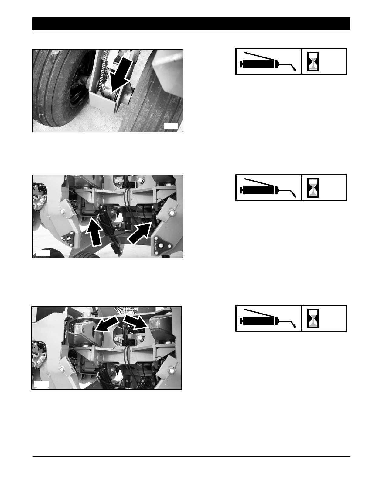
Great Plains Mfg., Inc.
Section 5 Maintenance and Lubrication
10
Opener Frame Pivots at Gauge Wheels
One zerk per pivot; two zerks total.
17354
17305
Type of Lubrication: Grease
Quantity = Until grease emerges from ends of pivot
10
Horizontal Pivot Pin
Three zerks per pivot pin; six zerks total.
Zerks accessible from rear of folded drill, or front of drill unfolded.
Type of Lubrication: Grease
17354
9/26/13
50
Vertical Pivot Pins
Two zerks per vertical pivot pin; four zerks total
Type of Lubrication: Grease
Quantity = Until grease emerges from end of pivot pin
2S-2600 and 2S-2600F Two-Section Folding Drill 195-200M-A
49
Page 52
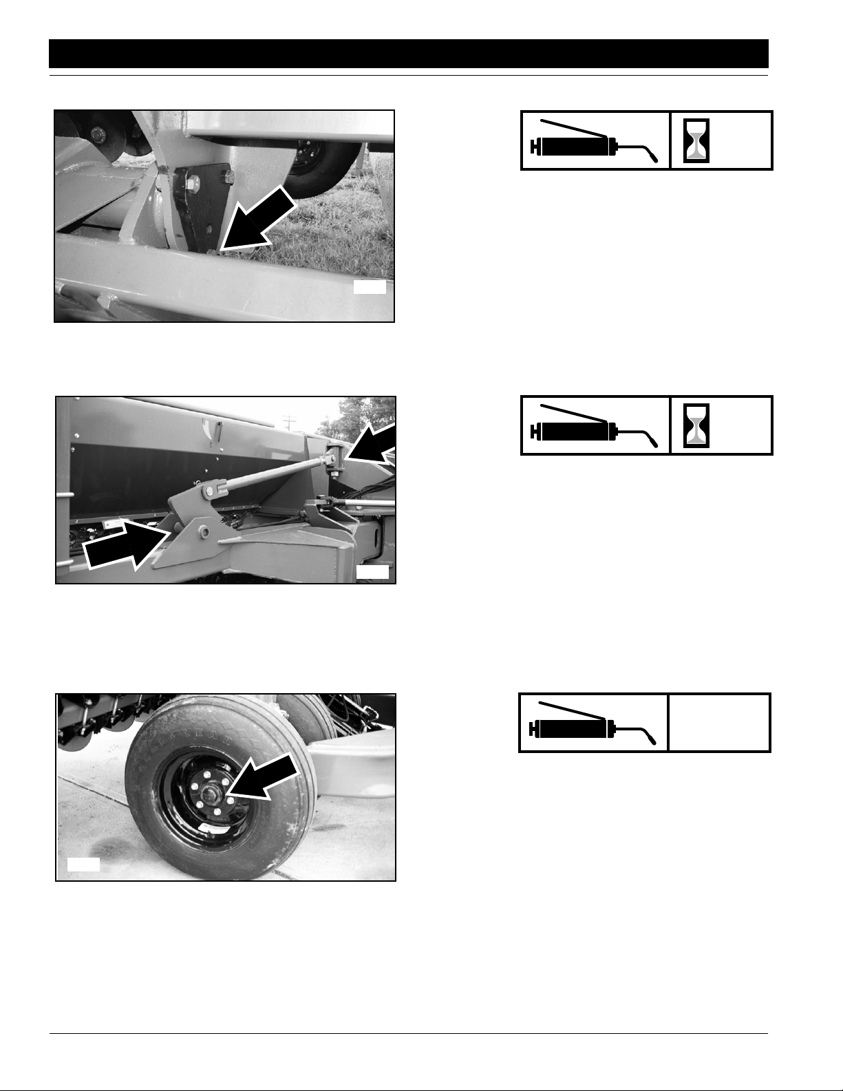
Section 5 Maintenance and Lubrication
17355
Great Plains Mfg., Inc.
50
Transport Axle Pivot Bearings
Two zerks per transport axle; four zerks total
Type of Lubrication: Grease
Quantity = Until resistance is felt
17309
20
Adjustment Link Pivot
Two zerks on each link; four zerks total
Type of Lubrication: Grease
Quantity = Until grease emerges
2-3 Years
Transport Hub Bearings
17314
2S-2600 and 2S-2600F Two-Section Folding Drill 195-200M-A 9/26/13
50
Type of Lubrication: Wheel bearing grease
Quantity = Repack
Page 53

Great Plains Mfg., Inc.
Section 5 Maintenance and Lubrication
2-3 Years
Gauge Wheel Drive Bearings
17305
17303
Type of Lubrication: Wheel bearing grease
Quantity = Repack
As
Required
Drive Chain, Speed-Change Shaft to Seed Cup
Type of Lubrication: Chain Lube
Quantity = Coat Thoroughly
15534
9/26/13
Drive Chain, Clutch to Speed-Change Shaft
Type of Lubrication: Chain Lube
Quantity = Coat Thoroughly
2S-2600 and 2S-2600F Two-Section Folding Drill 195-200M-A
As
Required
51
Page 54

Section 5 Maintenance and Lubrication
Great Plains Mfg., Inc.
As
Required
Drive Chain, Hub to Clutch Shaft
15536
Lubrication for Optional Markers
Type of Lubrication: Chain Lube
Quantity = Coat Thoroughly
10
Marker Hinge Points
Three zerks per marker.
17296
Type of Lubrication: Grease
Quantity = Until grease emerges
2-3 Years
Marker Disk Bearings
15545
2S-2600 and 2S-2600F Two-Section Folding Drill 195-200M-A 9/26/13
52
Type of Lubrication: Grease
Quantity = Repack
Page 55
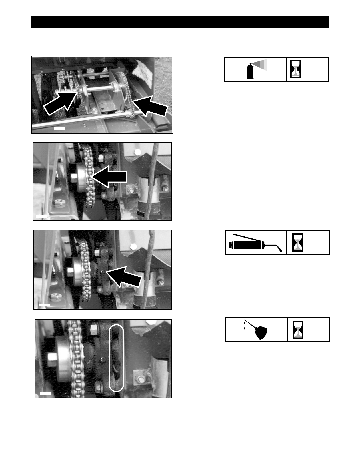
Great Plains Mfg., Inc.
Section 5 Maintenance and Lubrication
2S-2600F Additional Lubrication
16379
As
Required
Fertilizer Drive Chains
Type of Lubrication: Spray
Quantity = Coat chains thoroughly
16381
16381
16381
15
Fertilizer Shaft Bearings
Both ends of shafts; four zerks total
Type of Lubrication: Grease
Quantity = Until resistance is felt
30
Felt Barrier Seals
Both ends of shafts; four seals total
Type of Lubrication: Oil
Quantity = Soak seal
9/26/13
2S-2600 and 2S-2600F Two-Section Folding Drill 195-200M-A
53
Page 56

Section 5 Maintenance and Lubrication
Small Seeds Option Lubrication
17180
Great Plains Mfg., Inc.
As
Required
Drive Chains
Type of Lubrication: Spray
Quantity = Coat chains thoroughly
18082
Storage
Store drill where children do not play. If possible, store drill
inside for longer life.
1. Thoroughly clean drill boxes and seed cups. Do not
store drill with fertilizer or seed-treatment residue in
boxes and cups. Refer to 2S-2600F Clean Out, page
46.
2. Lubricate and adjust all roller chains.
3. Lubricate areas noted under Lubrication, page 48.
Take special care to oil seed-cup-drive sprockets in
the square bore.
4. Lock opener frames up for transport or disconnect
seed and fertilizer hoses from openers. Leaving seed
hoses connected when storing drill with openers lowered will cause permanent stretching and cracking of
hoses.
15
Shaft Bearings
Both ends of shafts; four zerks total
Type of Lubrication: Grease
Quantity = Until grease emerges
2S-2600 and 2S-2600F Two-Section Folding Drill 195-200M-A 9/26/13
54
Page 57
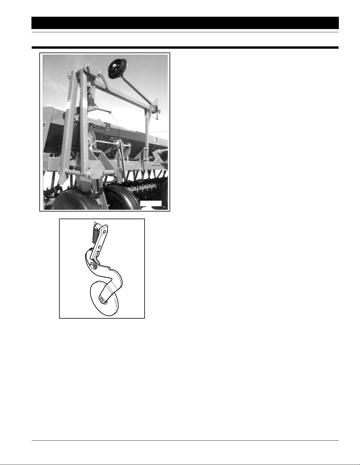
Great Plains Mfg., Inc.
Section 6 Options
Section 6 Options
Flat Folding Marker
The hydraulically operated, flat-fold markers leave a line for
you to follow on the next field pass. Markers are sold as single units for mounting on the left end on your drill or as dual
units for mounting on both ends of your drill. Dual markers
are plumbed together with a sequence valve so you can operate both markers on the same hydraulic circuit. Both marker options come with a double-selector valve, allowing you to
tie the marker hydraulic circuit into the fold hydraulic circuit.
For more information refer to:
• Marker Operation, “Operating Instructions,” page 21
• Marker Adjustments, “Adjustments,” page 39
• “Maintenance and Lubrication,” page 46
Marker Bundles
113-552A Single Left Hand Flat Fold Marker Package
113-553A Dual Flat Fold Marker Package
12677
17296
00 Series Seed-Lok Firming Wheel
The spring-loaded Seed-Lok firming wheels press seed directly into the bottom of the furrow, assuring the best seed-tosoil contact. The firming wheels promote even emergence
since seeds are planted and firmed at the same depth. The
wheels bolt directly to the scraper mount on your standard
drill openers.
Seed-Lok Bundle
122-193K Solid Stand Removable 5” Seed-Lok Assembly
122-266K Solid Stand Removable 6” Seed-Lok Assembly
9/26/13
2S-2600 and 2S-2600F Two-Section Folding Drill 195-200M-A
55
Page 58

Section 6 Options
15642
Great Plains Mfg., Inc.
Seed Cup Plugs
Seed-cup plugs are available to block off individual rows
when a wider row spacing is desired. Plugs are installed
by pushing them into the seed-cup openings on desired
rows.
Seed Cup Plugs
817-087C 1 3/4 Wide Feeder Cup Plug
13178
Shaft Monitor
The shaft monitor is an electronic monitoring system that
detects when the seed-cup shafts stop turning. If a seedcup shaft stops for 30 seconds, an alarm sounds and a
warning light flashes to designate the failed shaft.
For more information refer to:
• Shaft Monitor Operation, “Operating Instructions,”
page 21
Shaft Monitor Bundle
116-121A Vansco 3-Channel Shaft Monitor
Weight Kit
It will be necessary to purchase an additional weight kit
if you choose not to use markers with your HD00 Series
3S-4000 drill.
To order an additional Weight Kit, contact your Great
Plains dealer.
Weight Kit
171-097A 26/30/4000 Dual HD Weight Kit
171-099A 26/30/4000 Single HD Weight Kit
24454
2S-2600 and 2S-2600F Two-Section Folding Drill 195-200M-A 9/26/13
56
Page 59

Great Plains Mfg., Inc.
Section 6 Options
15641
Two Outlet Hydraulic Kit
To operate all drill functions, the standard 2S-2600 requires a
tractor with three remote valves. Tractors with two remote
valves can be used with the two-outlet hydraulic kit. Using a
double-selector valve mounted on the drill tongue, this kit combines the transport-lift and opener-lift circuits.
To operate a drill equipped with markers on a tractor with two
remote valves, you must install two kits – one to combine the
transport-lift and opener-lift circuits and one to combine the
marker and fold circuits.
For more information refer to:
• Hydraulic Hose Hookup,“Operating Instructions,” page
10
• Marker Operation,“Operating Instructions,” page 21
Two Outlet Tractor Hydraulic Bundle
194-122A Two Outlet Tractor Hydraulic Kit
15640
Dual Gauge Wheels
A dual-gauge-wheel upgrade is available. Dual gauge wheels
provide more flotation for your drill in loose field conditions.
Dual Gauge Wheel Update Kit
195-122A Dual Accessory Gauge Wheel Field Update Kit
Point Row Clutch
The 2S-2600 can be outfitted with clutches and controls that
allow you to raise and lower openers on each drill section independent of the other section.
For information on operating the clutches, refer to:
• Point Row Operation,“Operating Instructions,” page
20
Point Row Option
195-263A 2S-2600 Point Row Accessory
9/26/13
2S-2600 and 2S-2600F Two-Section Folding Drill 195-200M-A
57
Page 60
Section 6 Options
16375
Great Plains Mfg., Inc.
Fertilizer Box
You can modify the seedbox on your 2S-2600 for fertilizer application. The integrated seed box has a standard ratio of 60
percent seed and 40 percent fertilizer. The integratedfertilizer
box cleans out quickly and can be switch to all seed.
For more information refer to:
• Fertilizer Box Operation,“Operating Instructions,” page
20
• Fertilizer Rate Calibration,“Adjustments,” page 29
• 2S-2600F Clean Out,“Maintenance and Lubrication,”
page 46
The field update fertilizer package will be available in 1999.
For ordering information, contact your Great Plains dealer.
16669
Offset Box Divider
The 2600F-2S is equipped with standard dividers that partition the drill boxes into 60 percent seed and 40 percent
fertilizer. Optional offset dividers allow you to run 68 percent
seed and 32 percent fertilizer or 55 percent seed and 45 percent fertilizer.
To change the seed-to-fertilizer ratio using the optional dividers, refer to:
• Seed and Fertilizer Capacity,“Adjustments,” page 41
The offset divider will be available in 1999. For ordering information, contact your Great Plains dealer
2S-2600 and 2S-2600F Two-Section Folding Drill 195-200M-A 9/26/13
58
Page 61

Great Plains Mfg., Inc.
Section 7 Specifications and Capacities
Section 7 Specifications and Capacities
Row Spacing
Rows per Drill
Weight with Markers
Working Width
Transport Width
Transport Height
Transport Length
Field Length
Seedbox Capacity
Gauge Wheel Tires
Transport Wheel Tires
Tractor Requirements
6 inches 7.5 inches 10 inches
52 42 32
12,435 pounds 11,760 pounds 11,085 pounds
26 feet 2 inches 26 feet 4 inches 26 feet 10 inches
15 feet
8 feet 1.5 inches
22 feet 7 inches
27 feet 6 inches
86.4 bushels
9.5L x 15 6-ply; 6-bolt rim
11L x 15 12-ply; 6-bolt rim
110 horsepower
Three remote valves or two remote valves and optional kit
Tractors with load-sensing hydraulics may require a bypass valve, Great
Plains part number 810-400C. Contact your tractor dealer to verify if the
valve is needed.
NOTE: All tires are warranted by the original manufacturer of the tire. Tire warranty information can be found in the brochures included with your Operator’s and Parts Manuals or online at the manufacturer’s websites. For service assistance
or information, contact your nearest Authorized Farm Tire Retailer.
Manufacturer Website
Titan www.titan-intl.com
Goodyear www.goodyearag.com
Firestone www.firestoneag.com
9/26/13
2S-2600 and 2S-2600F Two-Section Folding Drill 195-200M-A
59
Page 62
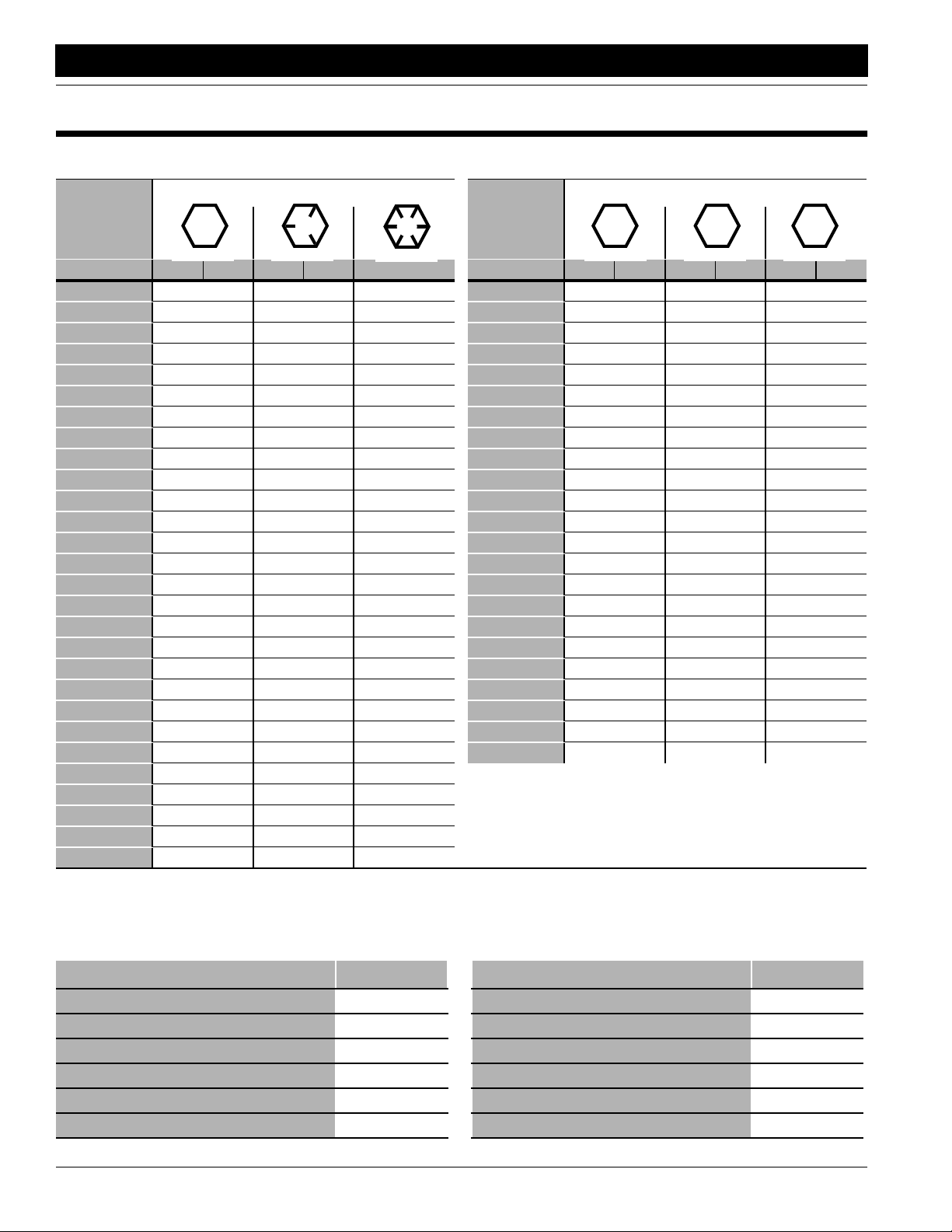
Appendix
Appendix
Torque Values Chart for Common Bolt Sizes
Great Plains Mfg., Inc.
Bolt Head Identification
Bolt Size
(Inches)
1
in-tpi
1/4" - 20 7.4 5.6 11 8 16 12 M 5 X 0.8 436597
1/4" - 28 8.5 6 13 10 18 14 M 6 X 1 7 5 11 8 15 11
5/16 - 18 15 11 24 17 33 25 M 8 X 1.25 17 12 26 19 36 27
5/16" - 24 17 13 26 19 37 27 M 8 X 1 18 13 28 21 39 29
3/8" - 16 27 20 42 31 59 44 M10 X 1.5 33 24 52 39 72 53
3/8" - 24 31 22 47 35 67 49 M10 X 0.75 39 29 61 45 85 62
7/16" - 14 43 32 67 49 95 70 M12 X 1.75 58 42 91 67 125 93
7/16" - 20 49 36 75 55 105 78 M12 X 1.5 60 44 95 70 130 97
1/2" - 13 66 49 105 76 145 105 M12 X 1 90 66 105 77 145 105
1/2" - 20 75 55 115 85 165 120 M14 X 2 92 68 145 105 200 150
9/16" - 12 95 70 150 110 210 155 M14 X 1.5 99 73 155 115 215 160
9/16" - 18 105 79 165 120 235 170 M16 X 2 145 105 225 165 315 230
5/8" - 11 130 97 205 150 285 210 M16 X 1.5 155 115 240 180 335 245
5/8" - 18 150 110 230 170 325 240 M18 X 2.5 195 145 310 230 405 300
3/4" - 10 235 170 360 265 510 375 M18 X 1.5 220 165 350 260 485 355
3/4" - 16 260 190 405 295 570 420 M20 X 2.5 280 205 440 325 610 450
7/8" - 9 225 165 585 430 820 605 M20 X 1.5 310 230 650 480 900 665
7/8" - 14 250 185 640 475 905 670 M24 X 3 480 355 760 560 1050 780
1" - 8 340 250 875 645 1230 910 M24 X 2 525 390 830 610 1150 845
1" - 12 370 275 955 705 1350 995 M30 X 3.5 960 705 1510 1120 2100 1550
1-1/8" - 7 480 355 1080 795 1750 1290 M30 X 2 1060 785 1680 1240 2320 1710
1 1/8" - 12 540 395 1210 890 1960 1440 M36 X 3.5 1730 1270 2650 1950 3660 2700
1 1/4" - 7 680 500 1520 1120 2460 1820 M36 X 2 1880 1380 2960 2190 4100 3220
1 1/4" - 12 750 555 1680 1240 2730 2010
1 3/8" - 6 890 655 1990 1470 3230 2380
1 3/8" - 12 1010 745 2270 1670 3680 2710
1 1/2" - 6 1180 870 2640 1950 4290 3160
1 1/2" - 12 1330 980 2970 2190 4820 3560
Grade 2 Grade 5
N · m2ft-lb3N · m ft-lb N · m ft-lb mm x pitch4N · m ft-lb N · m ft-lb N · m ft-lb
Torque tolerance + 0%, -15% of torquing values. Unless otherwise specified use torque values listed above.
Grade 8
Bolt Size
(Metric)
1
in-tpi = nominal thread diameter in inches-threads per inch
4
mm x pitch = nominal thread diameter in millimeters x thread pitch
Bolt Head Identification
5.8 8.8 10.9
Class 5.8 Class 8.8 Class 10.9
2
N· m = newton-meters
3
ft-lb= foot pounds
Tire Inflation Chart
Tire Size Inflation PSI Tire Size Inflation PSI
7.50 x 20" 4-Ply Drill Rib 28 11L x 15" 6-Ply Rib Implement 28
9.0 x 22.5 10-Ply Highway Service 70 70 11L x 15" 12-Ply Rib Implement 52
9.0 x 24" 8-Ply Rib Implement 40 12.5L x 15" 8-Ply Rib Implement 36
9.5L x 15" 6-Ply Rib Implement 32 12.5L x 15" 10-Ply Rib Implement 44
9.5L x 15" 8-Ply Rib Implement 44 16.5L x 16.1" 10-Ply Rib Implement 36
9.5L x 15" 12-Ply Rib Implement 60 41 x 15" x 18 - 22-Ply Rib Implement 44
2S-2600 and 2S-2600F Two-Section Folding Drill 195-200M-A 9/26/13
60
Page 63

Great Plains Mfg., Inc.
Appendix
Hydraulic Schematics
Opener Lift Circuit
WING
(P) LOWER
(R) RAISE
BYPASS
VALUE
FILTER
(CLOSED)
FOR
OPEN CTR
CTR
1
3
2
SHUTTLE
VALUE
OPENERS HYDRAULICS
FOR OPEN CENTER SYSTEMS
1
3
CBV
DOWN
PRESSURE
CHECK
2
1
2
R
T
CTR
CTR
WING
S/N DD1215- December 2004-
3
1
DOWN
CHECK
2
R
G
T
P
WING
3
23032
G
P
PRESSURE
9/26/13
WING
S/N DD1216+ January 2005+
BYPASS
VALUE
(CLOSED)
FOR
OPEN CTR
(R) RAISE
(P) LOWER
CTR
1
3
2
SHUTTLE
VALUE
OPENERS HYDRAULICS
FOR OPEN CENTER SYSTEMS
2S-2600 and 2S-2600F Two-Section Folding Drill 195-200M-A
1
3
CBV
DOWN
PRESSURE
CHECK
2
1
2
R
T
CTR
CTR
3
1
DOWN
PRESSURE
G
P
CHECK
FILTER
3
2
R
G
TP
WING
FILTER
WING
23033
61
Page 64

Appendix
BYPASS
VALV E
FILTER
3
CBV
Great Plains Mfg., Inc.
S/N DD1215- December 2004-
23030
R
1
2
G
P
T
CENTER
R
G
T
P
WING
(R)
RAISE
(P)
LOWER
S/N DD1216+ January 2005+
BYPASS
VALV E
OPENERS HYDRAULICS
FOR CLOSED CENTER SYSTEMS
R
1
3
CBV
2
G
T
P
CENTER
R
G
T
P
WING
FILTER
(R)
RAISE
(P)
LOWER
2S-2600 and 2S-2600F Two-Section Folding Drill 195-200M-A 9/26/13
62
OPENERS HYDRAULICS
FOR CLOSED CENTER SYSTEMS
23031
Page 65

Great Plains Mfg., Inc.
Appendix
Transport Fold Circuit
Transport Lift Circuit
9/26/13
18079
2S-2600 and 2S-2600F Two-Section Folding Drill 195-200M-A
63
Page 66
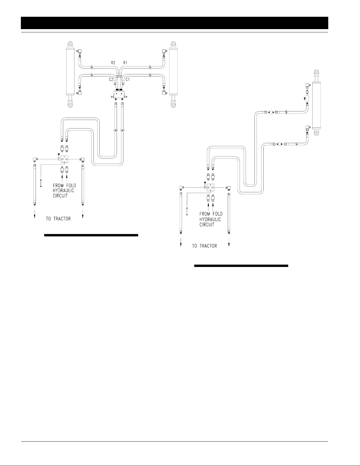
Appendix
Great Plains Mfg., Inc.
Dual Marker Hydraulics
Single Marker Hydraulics
2S-2600 and 2S-2600F Two-Section Folding Drill 195-200M-A 9/26/13
64
Page 67

Great Plains Mfg., Inc.
Appendix
Warranty
Great Plains Manufacturing, Incorporated warrants to the original purchaser that this seeding equipment will be free from defects in material
and workmanship for a period of one year from the date of original purchase when used as intended and under normal service and conditions
for personal use; 90 days for commercial or rental purposes. This Warranty is limited to the replacement of any defective part by Great Plains
Manufacturing, Incorporated and the installation by the dealer of any
such replacement part. Great Plains reserves the right to inspect any
equipment or part which are claimed to have been defective in material
or workmanship.
This Warranty does not apply to any part or product which in Great
Plains’ judgement shall have been misused or damaged by accident or
lack of normal maintenance or care, or which has been repaired or altered in a way which adversely affects its performance or reliability, or
which has been used for a purpose for which the product is not designed. This Warranty shall not apply if the product is towed at a speed
in excess of 20 miles per hour.
Claims under this Warranty must be made to the dealer which originally
sold the product and all warranty adjustments must by made through
such dealer. Great Plains reserves the right to make changes in materials or design of the product at any time without notice.
This Warranty shall not be interpreted to render Great Plains liable for
damages of any kind, direct, consequential, or contingent, to property.
Furthermore, Great Plains shall not be liable for damages resulting from
any cause beyond its reasonable control. This Warranty does not extend to loss of crops, losses caused by harvest delays or any expense
or loss for labor, supplies, rental machinery or for any other reason.
No other warranty of any kind whatsoever, express or implied, is
made with respect to this sale; and all implied warranties of merchantability and fitness for a particular purpose which exceed
the obligations set forth in this written warranty are hereby disclaimed and excluded from this sale.
This Warranty is not valid unless registered with Great Plains Manufacturing, Incorporated within 10 days from the date of original purchase.
9/26/13
2S-2600 and 2S-2600F Two-Section Folding Drill 195-200M-A
65
Page 68

Great Plains Manufacturing, Inc.
Corporate Office: PO. Box 5060
Salina, Kansas 67402-5060 USA
 Loading...