

Page 1
Predelivery Instructions
2S-2600 and 2S-2600F
Two-Section Folding Drill
Manufacturing, Inc.
www.greatplainsmfg.com
Read this manual entirely. When you see this symbol, the subsequent instructions and
!
warnings are serious - follow without exception. Your life and the lives of others depend
on it!
© Copyright 2006 Printed
2012-04-04
17262
Cover illustration may show optional equipment not supplied with standard unit.
195-201Q
Page 2

Table of Contents
Table of Contents
Great Plains Mfg., Inc.
Important Safety Information . . . . . . . . . . . . . . . . . 1
Safety Notations . . . . . . . . . . . . . . . . . . . . . . . . . 1
Safety Rules . . . . . . . . . . . . . . . . . . . . . . . . . . . . 1
Introduction . . . . . . . . . . . . . . . . . . . . . . . . . . . . . . . 2
Description of Unit . . . . . . . . . . . . . . . . . . . . . . . . 2
Using This Manual. . . . . . . . . . . . . . . . . . . . . . . . 2
Assembly and Setup Assistance . . . . . . . . . . . . . 2
Section 1 Assembly . . . . . . . . . . . . . . . . . . . . . . . . . 3
Tools Required. . . . . . . . . . . . . . . . . . . . . . . . . . . 3
Pre-Assembly Checklist. . . . . . . . . . . . . . . . . . . . 3
Installing Press Wheels . . . . . . . . . . . . . . . . . . . . 3
Installing Walkboards. . . . . . . . . . . . . . . . . . . . . . 4
Installing Reflector Decals . . . . . . . . . . . . . . . . . . 4
Installing Handles and Lights. . . . . . . . . . . . . . . . 5
Section 2 Setup . . . . . . . . . . . . . . . . . . . . . . . . . . . . 6
Tractor Hookup . . . . . . . . . . . . . . . . . . . . . . . . . . 6
Hydraulic Hose Hookup. . . . . . . . . . . . . . . . . . . . 6
Bleeding the Hydraulics . . . . . . . . . . . . . . . . . . . . 7
Bleeding Opener Lift Hydraulics . . . . . . . . . . 7
Bleeding Fold Hydraulics . . . . . . . . . . . . . . . . 8
Bleeding Transport Lift Hydraulics . . . . . . . . . 9
Bleeding Marker Hydraulics. . . . . . . . . . . . . . 9
Folding . . . . . . . . . . . . . . . . . . . . . . . . . . . . . . . . 10
Unfolding . . . . . . . . . . . . . . . . . . . . . . . . . . . . . . 11
Folding & Unfolding Quick Reference. . . . . . . . . 11
Frame Adjustments . . . . . . . . . . . . . . . . . . . . . . 12
Eyebolt Adjustment . . . . . . . . . . . . . . . . . . . 12
Link Tube . . . . . . . . . . . . . . . . . . . . . . . . . . . 12
Box Alignment . . . . . . . . . . . . . . . . . . . . . . . 12
Appendix . . . . . . . . . . . . . . . . . . . . . . . . . . . . . . . . . 14
Tire Inflation Chart . . . . . . . . . . . . . . . . . . . . . . . 14
Torque Values Chart for Common Bolt Sizes. . . 14
© Copyright 2006 All rights Reserved
Great Plains Manufacturing, Inc. provides this publication “as is” without warranty of any kind, either expressed or implied. While every precaution has been taken in the preparation
of this manual, Great Plains Manufacturing, Inc. assumes no responsibility for errors or omissions. Neither is any liability assumed for damages resulting from the use of the information contained herein. Great Plains Manufacturing, Inc. reserves the right to revise and improve its products as it sees fit. This publication describes the state of this product at the
time of its publication, and may not reflect the product in the future.
The following are trademarks of Great Plains Mfg., Inc.: Application Systems, Ausherman, Land Pride, Great Plains
All other brands and product names are trademarks or registered trademarks of their respective holders.
2S-2600 and 2S-2600F Two-Section Folding Drill 195-201Q 2012-04-04
Great Plains Manufacturing, Incorporated Trademarks
Printed in the United States of America.
Page 3

Important Safety Information
Important Safety Information
For your safety, thoroughly read “Important Safety Information” and “Operating Instructions” in the operator’s manual
before proceeding.
Safety Notations
The SAFETY ALERT SYMBOL indicates that there is a potential hazard to personal safety involved and extra safety precautions must be taken. When you see this symbol, be alert and
carefully read the message that follows it. In addition to design
and configuration of equipment, hazard control and accident
prevention are dependent upon the awareness, concern, prudence and proper training of personnel involved in the operation, transport, maintenance and storage of equipment.
Watch for the following safety notations throughout your operator’s manual.
!
DANGER!
Indicates an imminently hazardous situation which, if not
avoided, will result in death or serious injury. This signal word
is limited to the most extreme situations.
!
Great Plains Mfg., Inc.
!
WARNING!
Indicates a potentially hazardous situation which, if not avoided, could result in death or serious injury.
!
CAUTION!
Indicates a potentially hazardous situation which, if not avoided, may result in minor or moderate injury. It may also be used
to alert against unsafe practices.
Safety Rules
Most accidents are the result of negligence, carelessness or
failure to follow safety precautions. Though your implement is
designed with many built-in safety features, safety precautions
are mandatory to prevent accidents.
2S-2600 and 2S-2600F Two-Section Folding Drill 195-201Q 2012-04-04
1
Page 4

Great Plains Mfg., Inc.
Introduction
Introduction
Great Plains Manufacturing wants you to be satisfied with
any new machine delivered by the Great Plains Trucking
network. To ease the assembly task and produce a properly working machine, read this entire manual before assembling or setting up new equipment.
IMPORTANT: A crucial point of information about the
preceding topic. For safe and correct operation, read
and follow the directions provided before continuing.
Description of Unit
The 2S-2600 is a towed seeding implement. This two-section drill has a working width of 26 feet and folds to a transport width of 15 feet. The drill has straight-arm, doubledisk openers. The opener disks make a seed bed, and
seed tubes mounted between the disks place seed in the
furrow. Press wheels following the opener disks close the
furrow and gauge opener seeding depth. A T-handle on
the opener body is for seeding-depth adjustments. Seeding rates are adjustable with the seed-rate-adjustment
handle and the sprocket box.
The 2S-2600 features active hydraulic down pressure on
the opener frames. When used on a tractor with closedcenter hydraulics, constant down pressure ensures even
opener penetration in uneven ground. Hydraulic down
pressure is adjustable at a single point.
The 2S-2600F allows you to plant seed and apply fertilizer
in the same field pass. Dividers partition the drill boxesinto
seed and fertilizer compartments. The openers apply dry
fertilizer to the seed trench before the furrow is closed. You
also can use both compartments for seed.
Intended Usage
Use this implement to seed production-agriculture crops
in conventional-tillage applications.
Using This Manual
This manual was written to help you assemble and prepare the new machine for the customer. The manual includes instructions for assembly and setup. Read this
manual and follow the recommendations for safe, efficient
and proper assembly and setup.
An operator’s manual is also provided with the new machine. Read and understand “Important Safety Informa-
tion” and “Operating Instructions” in the operator’s
manual before assembling the machine. As a reference,
keep the operator’s manual on hand while assembling.
The information in this manual is current at printing. Some
parts may change to assure top performance.
Definitions
The following terms are used throughout this manual.
Right and left as used in this manual are determined by
facing the direction the machine will travel while in use unless otherwise stated.
NOTE: Useful information about the preceding topic.
Assembly and Setup Assistance
To order additional copies of predelivery instructions or
operator’s and parts manuals, write to the following address. Include model numbers in all correspondence.
If you do not understand any part of this manual or have
other assembly or setup questions, assistance is available. Contact
Product Support
Great Plains Mfg. Inc., Service Department
P.O. Box 5060
Salina, KS 67402-5060
2012-04-04
2S-2600 and 2S-2600F Two-Section Folding Drill 195-201Q
2
Page 5
Section 1 Assembly
Section 1 Assembly
Great Plains Mfg., Inc.
The following headings are step-by-step instructions for
assembling the drill. Begin with Tools Required and Pre-
Assembly Checklist to make sure you have all necessary
parts and equipment. Then proceed with Installing Press
Wheels. Follow each step to make the job as quick and
safe as possible and produce a properly working machine.
The drill is shipped via flat bed truck. It is the dealer’s responsibility to unload the new machine. Unload all equipment before beginning assembly. Do not attempt any
assembly work while the drill is on the truck.
Tools Required
•
Forklift, overhead hoist or loader
• General hand tools
Pre-Assembly Checklist
1. Read and understand “Important Safety Information,” page 1 before assembling.
2. Have at least two people on hand while assembling.
3. Make sure assembly area is level and free of obstructions (preferably an open concrete area).
4. Have all major components.
5. Have all fasteners and pins shipped with drill.
IMPORTANT: If a pre-assembled part or fastener is
temporarily removed, remember where it goes. Keep
the parts separated.
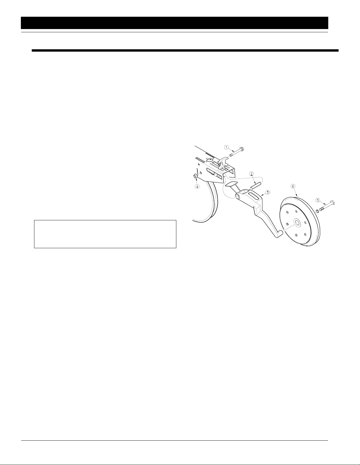
Installing Press Wheels
Refer to Figure 1-1.
1. Remove 1/2-by-3 3/4-inch flange bolt (1) and flange
lock nut (4) from each opener body.
2. Leave pivot bushing (2) in place and bolt press-wheel
arm (3) to opener with 1/2-by-3 3/4-inch flange bolt (1)
and lock nut (4). Repeat for all openers.
3. Remove 5/8-inch bolt (5) from each press-wheel arm
(3) and use bolts to assemble press wheels (6) to
press-wheel arms.
15658
6. Have a copy of the parts manual on hand. If unsure of
proper placement or use of any part or fastener, refer
to the parts manual.
7. Check that all working parts are moving freely, bolts
are tight and cotter pins are spread.
8. Check for proper tension and alignment on all drive
chains.
9. Check that all safety labels and reflectors are correctly
located and legible. Replace if improperly located or
damaged. Refer to Safety Labels, “Important Safety
Information” in the operator’s manual.
10. Inflate tires to recommended pressure as listed on
Tire Inflation Chart, “Appendix,” page 14. Tighten
wheel bolts as specified on Torque Values Chart, “Ap-
pendix,” page 14.
Figure 1-1
Press Wheel Arm and Press Wheel Assembly
2S-2600 and 2S-2600F Two-Section Folding Drill 195-201Q 2012-04-04
3
Page 6
Great Plains Mfg., Inc.
Section 1 Assembly
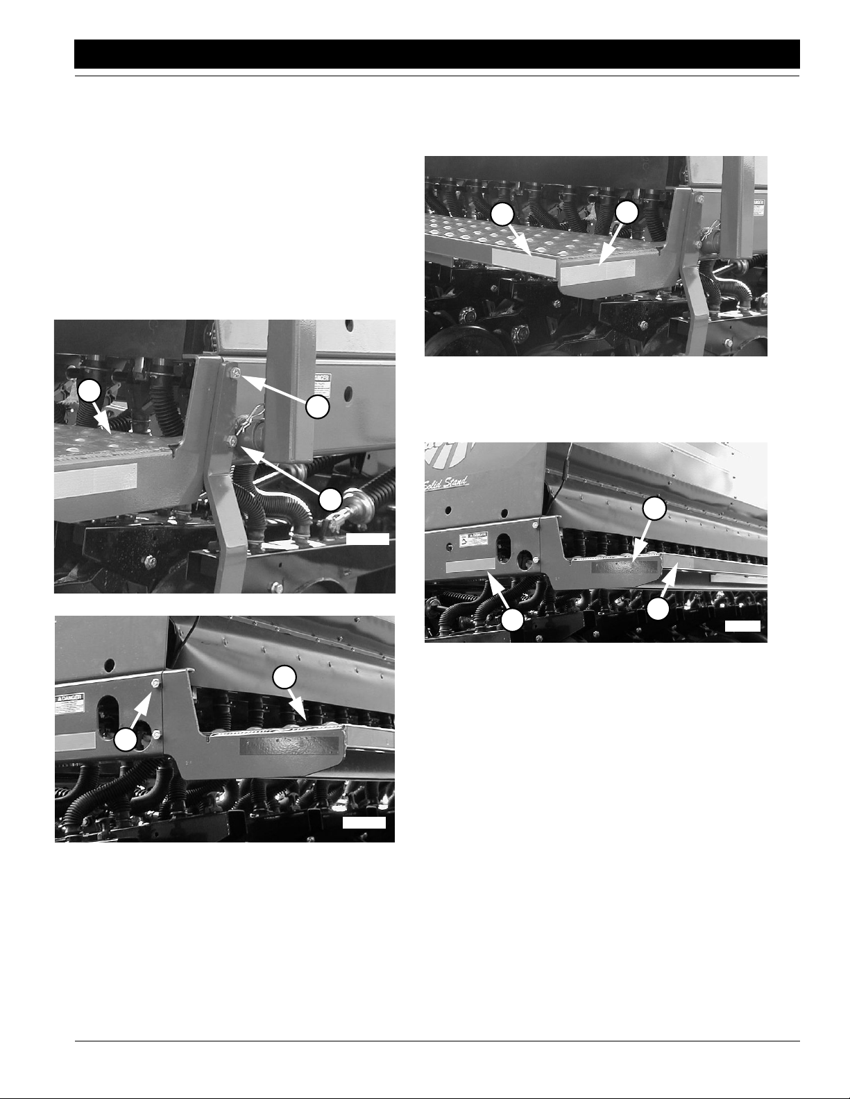
Installing Walkboards
Refer to Figure 1-2.
1. Remove 1/2-by-1 3/4-inch bolts (1) and steps (2) from
outside end panels. Remove 1/2-by-1 1/4-inch bolts
(3) from inside end panels.
2. Bolt walkboards (4) to box-support channels. Use 1/2by-1 1/4-inch bolts (3), lock washers and hex nuts on
inside ends of drill. Use 1/2-by-1 3/4-inch bolts (1),
lock washers and hex nuts to bolt step (2) and walkboard (4) on outside ends of drill.
NOTE: Steps (2) are not interchangeable. They jog away
from end panel and extend back when bolted on correctly.
4
1
2
Installing Reflector Decals
On outside ends of drill boxes, place amber reflectors on
outside (1) and back (2) of walkboards. Refer to Figure 1-
3.
12
15566
Figure 1-3
Install Reflectors, Outside Ends
On inside ends of drill boxes, place red reflectors on inside
(1) and amber reflectors on back (2) of walkboards. Install
daytime reflectors (3) on the inside. Refer to Figure 1-4.
1
Figure 1-2
Walkboard and Step Assembly
3
Figure 1-2
Walkboard and Step Assembly
15566
2
3
Figure 1-4
4
15528
Install Reflectors, Inside Ends
15528
2012-04-04
2S-2600 and 2S-2600F Two-Section Folding Drill 195-201Q
4
Page 7

Section 1 Assembly
Installing Handles and Lights
1. On outside ends of drill boxes, bolt handles to boxes
as shown in Figure 1-5. Use 1/2-inch, hex-flange
screws and lock nuts.
17347
Figure 1-5
Install Box Handles
2. On inside ends of drill boxes, bolt warning lights to
boxes as shown in Figure 1-6. Use 1/2-inch, hexflange screws (1) and lock nuts.
3. Plug warning-light leads into drill harness (2).
Great Plains Mfg., Inc.
1
2
17346
Figure 1-6
Install Warning Lights
4. Check lights for correct installation. Fold drill, then
check that both lights have an amber and a red lens
facing toward rear of drill. If necessary, re-install lights
properly.
2
2S-2600 and 2S-2600F Two-Section Folding Drill 195-201Q 2012-04-04
5
Page 8

Great Plains Mfg., Inc.
Section 2 Setup
Section 2 Setup
This section covers drill preperation and setup. You must
hook the drill hydraulics to the tractor, bleed the drill hydraulics and make any necessary frame adjustments.
This section also includes instructions for folding and unfolding the drill. Read these instructions carefully before
folding or unfolding the drill.
Tractor Hookup
!
DANGER!
You may be severely injured or killed by being crushed between
the tractor and drill. Do not stand or place any part of your
body between drill and moving tractor. Stop tractor engine and
set park brake before installing the hitch pin.
!
WARNING!
This drill can have positive and negative tongue weight, which
can work the hitch pin loose during transport. To avoid serious
injury or death due to a road accident, always use a clevis hitch
or clevis drawbar with a locking-style hitch pin.
1. Use a locking-style hitch pin that is sized to match the
holes in the hitch and drawbar. Hitch drill to tractor
drawbar.
2. Securely attach safety chain to an anchor on tractor
capable of pulling drill.
3. Store jack on storage tube on top of tongue as shown
in Figure 2-1.
Hydraulic Hose Hookup
!
WARNING!
Escaping fluid under pressure can penetrate the skin causing
serious injury. Avoid the hazard by relieving pressure before
disconnecting hydraulic lines. Use a piece of paper or cardboard, NOT BODY PARTS, to check for suspected leaks. Wear
protective gloves and safety glasses or goggles when working
with hydraulic systems. If an accident occurs, see a doctor immediately. Any fluid injected into the skin must be surgically removed within a few hours or gangrene may result.
Great Plains hydraulic hoses are color coded to help you
hookup hoses to your tractor outlets. Hoses that go to the
same remote valve are marked with the same color.
Color Hydraulic Function
Red Opener Lift
Blue Transport Lift
White Fold
Orange Marker
To distinguish hoses on the same hydraulic circuit, refer to
plastic hose holders. See Figure 2-2. Hoses under extended-cylinder symbol feed cylinder base ends. Hoses under
retracted-cylinder symbol feed cylinder rod ends.
15563
Figure 2-1
Jack Storage Location
4. Plug drill electrical lead into tractor seven-pin connector.
2012-04-04
17641
Figure 2-2
Hydraulic Hose Color Ties
IMPORTANT: To run drill in the field on tractors with
open-center hydraulics or on tractors with fixed-displacement hydraulic pumps, you must install a Great
Plains kit, part number 194-143A. You can set up drill
and bleed hydraulics with either an open- or closedcenter system.
2S-2600 and 2S-2600F Two-Section Folding Drill 195-201Q
6
Page 9

Section 2 Setup
Great Plains Mfg., Inc.
1. Connect opener-lift hoses to circuit designated for hy-
draulic-motor control.
2. Connect transport-lift hoses to tractor remote valve.
3. Connect fold hoses to tractor remote valve.
NOTE: If your tractor has only two remote valves, you must
install a double-selector valve to combine the transport-lift
and opener-lift circuits. Refer to Two Outlet Hydraulic Kit,
“Options,” in the operator’s manual.
Bleeding the Hydraulics
To function properly, the hydraulics must be free of air. If
hydraulics are not bled, they will operate with jerky, uneven
motions and could cause wings to drop rapidly during folding or unfolding. Complete the following procedures during initial drill setup.
!
WARNING!
Rasing the openers on the unfolded, unhitched drill will cause
the drill tongue to rise suddenly, which could cause serious injury or death. Be certain that the drill is hitched securely to your
tractor drawbar and the safety chain is securely attached to the
tractor before raising the openers and unfolding the drill.
!
WARNING!
Escaping fluid under pressure can penetrate the skin causing
serious injury. Avoid the hazard by relieving pressure be-
fore disconnecting hydraulic lines. Use a piece of pa-
per or cardboard, NOT BODY PARTS, to check
for suspected leaks. Wear protective gloves
and safety glasses or goggles when working with hydraulic systems. If an accident
occurs, see a doctor immediately. Any fluid injected into the skin must be surgical-
ly removed within a few hours or
gangrene
could result.
Bleeding Opener Lift Hydraulics
Refer to Figure 2-3.
1. Check hydraulic fluid level intractor reservoir and fill to
proper level. Add fluid to system as needed. System
capacity for entire drill is about 4 1/2 gallons.
2. Make sure opener frames are locked up in road position. Refer to Opener Lock Up,“Operation Instruc-
tions,” in the operator’s manual.
3. Turn knob on both pressure-control valves (1) completely counterclockwise, then turn valves clockwise
far enough to build up 1000 psi (about three turns).
4. Turn knob on bypass valve (2) completely clockwise
for no oil flow.
5. Loosen hose-end fittings (3) at the locations shown in
Figure 2-3.
NOTE: Do not loosen an O-ring fitting for bleeding. Bleeding air from an O-ring fitting will damage the seal.
6. Slowly supply oil to top side of pressure-control valves
until oil begins to appear at a loosened hose fitting. As
oil begins to appear at a fitting, tighten that fitting.
7. Slowly supply oil to bottom side of pressure-control
valves until oil begins to appearat remaining loosened
hose fitting. As oil begins to appear at the fitting, tighten fitting. Continue to supply oil to bottom side of pressure-control valves until all openers are raised
completely.
8. Move opener transport locks to field position and cycle
openers up and down ten times. Each time you lower
openers, hold tractor remote lever until opener circuit
builds up to pressure set at control valves.
9. After cycling openers, return opener transport locks to
road position.
Figure 2-3
Bleeding Opener Lift Hydraulics
20004
2S-2600 and 2S-2600F Two-Section Folding Drill 195-201Q 2012-04-04
7
Page 10

Great Plains Mfg., Inc.
Section 2 Setup
Bleeding Fold Hydraulics
1. Check hydraulic fluid level intractor reservoir and fill to
proper level. Add fluid to system as needed.
2. With drill unfolded and fold cylinders completely extended, disconnect rod-end pins and swing cylinders
so they will not contact anything when extended.
3. Loosen rod-end-hose fitting at elbow on left fold cylinder (1). See Figure 2-4.
NOTE: Do not loosen an O-ring fitting. Bleeding air from
an O-ring fitting will damage the seal.
4. Slowly supply oil to rod end of fold cylinders until oil
appears at loosened hose fitting. Tighten fitting and
completely retract fold cylinders.
5. With cylinders completely retracted, loosen base-endhose fitting at elbow on left fold cylinder (2). See Figure 2-4.
6. Slowly supply oil to base end of fold cylinders until oil
appears at loosened hose fitting. Tighten fitting and
cycle fold cylinders in and out several times.
7. Repin cylinder-rod clevis.
2012-04-04
Figure 2-4
Bleeding Fold Hydraulics
2S-2600 and 2S-2600F Two-Section Folding Drill 195-201Q
17299
8
Page 11

Section 2 Setup
Great Plains Mfg., Inc.
Bleeding Transport Lift Hydraulics
1. Check hydraulic fluid level intractor reservoir and fill to
proper level. Add fluid to system as needed.
2. With drill lowered into field position, loosen base-endhose fitting at elbow on right-hand transport-lift cylinder (1). See Figure 2-5.
3. Slowly supply oil to base end of transport-lift cylinders
until oil appears at loosened hose fitting. As oil appears at the fitting, tighten fitting.
4. Completely extend transport-lift cylinders and immediately lock cylinders by flipping up the cylinder lock
channels on both transport-lift cylinders. Refer to Figure 2-10, page 10.
!
WARNING!
The hydraulics could fail, causing the openers to fall and crush
you. To avoid serious injury or death, always secure cylinder
lock channels over extended transport-lift cylinders before
working under openers.
5. When cylinder lock channels are in place, loosen rodend-hose fitting at elbow on left transport-lift cylinder
(2). See Figure 2-5.
6. Slowly supply oil to rod end of transport-lift cylinders
until oil appears at loosened hose fitting. As oil begins
to appear at the fitting, tighten fitting.
7. Extend transport-lift cylinders and remove cylinder
lock channels. Completely cycle transport-lift hydraulics several times.
Bleeding Marker Hydraulics
!
CAUTION!
You may be injured if hit by a folding or unfolding marker.
Markers may fall quicklyand unexpectedlyif the hydraulics fail.
Never allow anyone near the drill when folding or unfolding
markers.
1. Make sure tractor hydraulic reservoir is full.
2. With markers unfolded in field position, crack hydraulic-hose fittings at base and rod ends of each marker
cylinder.
3. With tractor at idle speed, activate tractor hydraulic
valve forward until oil appears at one fitting. When oil
begins to seep out around a fitting, tighten that fitting.
Reverse tractor hydraulic valve until oil appears at opposite hose fitting and tighten that fitting.
4. If you have dual markers, activate your tractor hydraulic valve forward again until oil seeps out around one
fitting on other marker cylinder and tighten that fitting.
Reverse tractor hydraulic valve until oil seeps out
around remaining hose fitting and tighten it.
5. Fold and unfold markers slowly to work out all air. Use
caution when folding and unfolding markers for the
first time, checking for pinching and kinking of hoses.
17298
Figure 2-5
Bleeding Transport Lift Hydraulics
2S-2600 and 2S-2600F Two-Section Folding Drill 195-201Q 2012-04-04
9
Page 12

Great Plains Mfg., Inc.
Section 2 Setup
Folding
1. Park tractor and drill on level ground with tractor transmission in park. Be aware of clearance needed to fold
the drill.
2. Hydraulically raise openers completely.
3. Raise drill with transport-lift cylinders until cylinders
are extended completely.
17349
Figure 2-6
Raising Drill for Folding
4. Slowly supply oil to rod end of fold circuit. Fold drill until both box frames are secured in folding latch.
6. At rear ofdrill, lock opener frames into road position as
shown in Figure 2-9.
17353
Figure 2-9
Opener Lock Up
7. Rotate cylinder lock channels over rods on both transport-lift cylinders as shown in Figure 2-10.
17316
Figure 2-7
Folding Latch
5. At front of drill, lock opener frames into road position
as shown in Figure 2-8.
15549
Figure 2-8
Opener Lock Up
2012-04-04
15552
Figure 2-10
Cylinder Lock Channels Inserted for Transport
IMPORTANT: Make sure u-shaped clips in lock channels clasp cylinder rods securely. Clips must hold
channels in position until cylinders settle against
channels. You may need to adjust a clip by turning the
bolt inside the channel.
8. Allow transport-lift cylinders to settle against lock
channels.
9. Before transporting, check that hydraulic cylinders
have settled against thelock channels and are holding
the channels securely.
2S-2600 and 2S-2600F Two-Section Folding Drill 195-201Q
10
Page 13

Section 2 Setup
Unfolding
1. At front of drill, prop up latch pawl (1) as shown in Figure 2-11 so folding latch will release boxes.
Great Plains Mfg., Inc.
IMPORTANT: Do not lower openers until drill is unfolded or you will damage the drill tires.
1
17319
Figure 2-11
Latch Pawl Positioned for Folding
2. At front and rear of drill, position opener transport
locks in field position as shown in Figure 2-12.
4. Slowly supply oil to base end of fold circuit. Unfold drill
by extending fold cylinders completely.
5. Completely retract transport-lift cylinders.
6. Completely lower openers to allow opener transport
locks to disengage.
Folding & Unfolding Quick Reference
To Fold Drill
1. Raise openers.
2. Extend transport cylinders.
3. Fold drill.
4. Lock opener frames and transport cylinders.
To Unfold Drill
1. Position latch pawl for release.
2. Unlock opener frames.
3. Unlock transport-lift cylinders.
4. Unfold drill.
IMPORTANT: Do not lower openers until drill is unfolded or you will damage the drill tires.
15548
Figure 2-12
Opener Frames Unlocked
3. Supply oil to transport-lift cylinders until cylinders are
extended completely and drill is raised completely.
Rotate cylinder lock channels off cylinder rods as
shown in Figure 2-13.
15551
Figure 2-13
Cylinder Lock Channels Removed for Field Use
5. Retract transport lift cylinders.
6. Lower openers.
2S-2600 and 2S-2600F Two-Section Folding Drill 195-201Q 2012-04-04
11
Page 14

Great Plains Mfg., Inc.
Section 2 Setup
Frame Adjustments
Eyebolt Adjustment
Before using the drill, check that opener frames are level
across drill. When fully raised, top of opener mounts (1)
should clear bottom of drill frame tube by no more than
1/2 inch.
Adjust opener frames so all openers have the same clearance. Loosen jam nut (2) on opener-lift cylinders and turn
adjustment nut. See Figure 2-14. When openers are at
correct height, retighten jam nut. Repeat at each openerlift cylinder if necessary.
2
1
17308
Box Alignment
To check and adjust box alignment:
1. Place a block ahead of each wing gauge wheel. Pull
drill forward against blocks to rock frames back. Pull
forward until stop bolts are firmly against toolbars. Refer to Figure 2-16 for stop-bolt location.
2. Check for proper alignment by running a string line
across back of drill toward outside ends of wings. For
proper alignment, outside ends of boxes should be
about 1 inch ahead of inside ends. See Figure 2-17.
3. To adjust box alignment, shorten or lengthen stop
bolts to change contact point with toolbars. Adjust
stop bolts in or out until outside ends of boxes are 1
inch ahead of inside ends.
Figure 2-14
Eyebolt Adjustment for Opener Frame Height
Link Tube
The link tube shown in Figure 2-15 controls folding height
of outer end of drill box. If drill boxes do not catch in folding
latch when folding, adjust length of links to lower or raise
ends of boxes.
To lower or raise ends of drill boxes:
1. Unfold and lower drill.
2. Pull upper pin (1).
3. Unlock jam nut (2).
4. Thread clevis in or out to lengthen or shorten link.
5. Replace pin and tighten nut.
2
1
17357
Figure 2-16
Stop Bolt Location
2012-04-04
Figure 2-15
Adjustment Link
17307
2S-2600 and 2S-2600F Two-Section Folding Drill 195-201Q
12
Page 15

Section 2 Setup
Great Plains Mfg., Inc.
Figure 2-17
Wing Box Alignment
2S-2600 and 2S-2600F Two-Section Folding Drill 195-201Q 2012-04-04
13
17300
Page 16

Great Plains Mfg., Inc.
Appendix
Appendix
Torque Values Chart for Common Bolt Sizes
Bolt Head Identification
Bolt Size
(Inches)
1
in-tpi
1/4" - 20 7.4 5.6 11 8 16 12 M 5 X 0.8 436597
1/4" - 28 8.5 6 13 10 18 14 M 6 X 1 7 5 11 8 15 11
5/16 - 18 15 11 24 17 33 25 M 8 X 1.25 17 12 26 19 36 27
5/16" - 24 17 13 26 19 37 27 M 8 X 1 18 13 28 21 39 29
3/8" - 16 27 20 42 31 59 44 M10 X 1.5 33 24 52 39 72 53
3/8" - 24 31 22 47 35 67 49 M10 X 0.75 39 29 61 45 85 62
7/16" - 14 43 32 67 49 95 70 M12 X 1.75 58 42 91 67 125 93
7/16" - 20 49 36 75 55 105 78 M12 X 1.5 60 44 95 70 130 97
1/2" - 13 66 49 105 76 145 105 M12 X 1 90 66 105 77 145 105
1/2" - 20 75 55 115 85 165 120 M14 X 2 92 68 145 105 200 150
9/16" - 12 95 70 150 110 210 155 M14 X 1.5 99 73 155 115 215 160
9/16" - 18 105 79 165 120 235 170 M16 X 2 145 105 225 165 315 230
5/8" - 11 130 97 205 150 285 210 M16 X 1.5 155 115 240 180 335 245
5/8" - 18 150 110 230 170 325 240 M18 X 2.5 195 145 310 230 405 300
3/4" - 10 235 170 360 265 510 375 M18 X 1.5 220 165 350 260 485 355
3/4" - 16 260 190 405 295 570 420 M20 X 2.5 280 205 440 325 610 450
7/8" - 9 225 165 585 430 820 605 M20 X 1.5 310 230 650 480 900 665
7/8" - 14 250 185 640 475 905 670 M24 X 3 480 355 760 560 1050 780
1" - 8 340 250 875 645 1230 910 M24 X 2 525 390 830 610 1150 845
1" - 12 370 275 955 705 1350 995 M30 X 3.5 960 705 1510 1120 2100 1550
1-1/8" - 7 480 355 1080 795 1750 1290 M30 X 2 1060 785 1680 1240 2320 1710
1 1/8" - 12 540 395 1210 890 1960 1440 M36 X 3.5 1730 1270 2650 1950 3660 2700
1 1/4" - 7 680 500 1520 1120 2460 1820 M36 X 2 1880 1380 2960 2190 4100 3220
1 1/4" - 12 750 555 1680 1240 2730 2010
1 3/8" - 6 890 655 1990 1470 3230 2380
1 3/8" - 12 1010 745 2270 1670 3680 2710
1 1/2" - 6 1180 870 2640 1950 4290 3160
1 1/2" - 12 1330 980 2970 2190 4820 3560
Torque tolerance + 0%, -15% of torquing values. Unless otherwise specified use torque values listed above.
Grade 2 Grade 5
N · m2ft-lb3N · m ft-lb N · m ft-lb mm x pitch4N · m ft-lb N · m ft-lb N · m ft-lb
Grade 8
Bolt Size
(Metric)
1
in-tpi = nominal thread dia.in inches-threads per inch
2
N· m = newton-meters
3
ft-lb= foot pounds
4
mm x pitch = nominal thread dia. in millimeters x thread pitch
Bolt Head Identification
5.8 8.8 10.9
Class 5.8 Class 8.8 Class 10.9
Tire Inflation Chart
Tire Size Inflation PSI Tire Size Inflation PSI
7.50 x 20" 4-Ply Drill Rib 28 11L x 15" 6-Ply Rib Implement 28
9.0 x 22.5 10-Ply Highway Service 70 70 11L x 15" 12-Ply Rib Implement 52
9.0 x 24" 8-Ply Rib Implement 40 12.5L x 15" 8-Ply Rib Implement 36
9.5L x 15" 6-Ply Rib Implement 32 12.5L x 15" 10-Ply Rib Implement 44
9.5L x 15" 8-Ply Rib Implement 44 16.5L x 16.1" 10-Ply Rib Implement 36
9.5L x 15" 12-Ply Rib Implement 60 21.5 x 16.1” SC 10-Ply Rib Implement 28
2012-04-04
2S-2600 and 2S-2600F Two-Section Folding Drill 195-201Q
14
Page 17

Great Plains Manufacturing, Inc.
Corporate Office: PO. Box 5060
Salina, Kansas 67402-5060 USA
 Loading...