

Page 1

Great Plains Mfg., Inc.
Installation Instructions
2S-2600 2 Section Folding Drill
Point Row Option
Used with:
• 2S-2600
General Information
When you see this symbol, the subsequent instructions and
warnings areserious- follow without exception. Your life and
!
!
the lives of others depend on it!
These instructions explain how to install the Point
Row option. The Point Row option allows you to
raise and lower openers on each drill section
independently.
These instructions apply to:
195-299A 2S-2600PointRowACC2004 CBV
Manual Update
Referto the 2S-2600 operator’smanual for detailed
information on safely operating, adjusting, troubleshooting and maintaining the Point Row option.
Refer to the parts manual for part identification.
195-200M-A Operator’sManual
195-200P Parts Manual
Before You Start
Page 8 is a detailed listing of parts included in the
PointRowoption package. Use thislist to inventory
parts received.
Tools Required
• Basic hand tools
Definitions
Right-hand (RH) and left-hand (LH) as used in this
manual are determined by facing the direction the
machine will travel while in use unless otherwise
stated.
Overview of Installation
Thepointrowvalve blockwill be plumbed directly after the filter on the drill. Oil from the valve block is
directed to both the LH and RH wing reducing
valves all the time. With no power to a solenoid, oil
flows to the P port on the reducing valve, and the
openers are pushed down. Whenpower is supplied
to a solenoid, oilis routed to theTank port on the reducing valve and the openers will raise.
The point row valve block will be bolted toa plate
on the drill just ahead of the base end of the fold
cylinders. Two bulk head hydraulic T fittings pass
through this plate from the original plumbing.
These fittings will be removed to make room for
the valve.
The Counterbalance valve (CBV) supplied with
the point row kit will hang under the LH pressure
reducing valve.
TheCounterbalance valvewith thepoint row kit is
thicker than the reducing valveit is plumbed to.
Because of this, the pressure LH reducing valve
willneedto be shimmed outwithwashersto make
room for the new valve.
Center and Wings Vs.LH andRH wings.The drill
is originally plumbed so the two cylinders at the
center of the drillshared a reducing valve and the
outercylinderssharedanother. Withthepointrow
option, the drill plumbing is altered so the LH reducing valve controls the LH wing and the RH
valve controls the RH wing.
A solenoid valve will be installed in the bypass
valveblocklocated on the drill. The solenoid valve
blocksflow throughthe bypassvalve everytime a
point row switch is activated. This stops the bypass oil and lets the tractor pressure increase
enough to raise the openers off the ground when
a section is shut off.
OncethePointRowkit has been installed,thedrill
needs to be raised and loweredso the complete
installation can be checked AND the new Counterbalance valve can be checkedand adjusted if
needed. Refer to "Adjusting the valve" at the end
of these instructions.
© Copyright 2004 Printed
2/22/2005
195-300M
Page 2
Point Row Option
2
Great Plains Mfg., Inc.
Assembly Instructions
Hook the drill to a tractor. Move the opener lock
handles to "Field", unfold the drill and lower the
openers to the ground. Place the remote lever in
float position to relieve any residual hydraulic
pressure. Clean the area around the pressure reducing valves bywashing or using compressed
air.
Disassembly
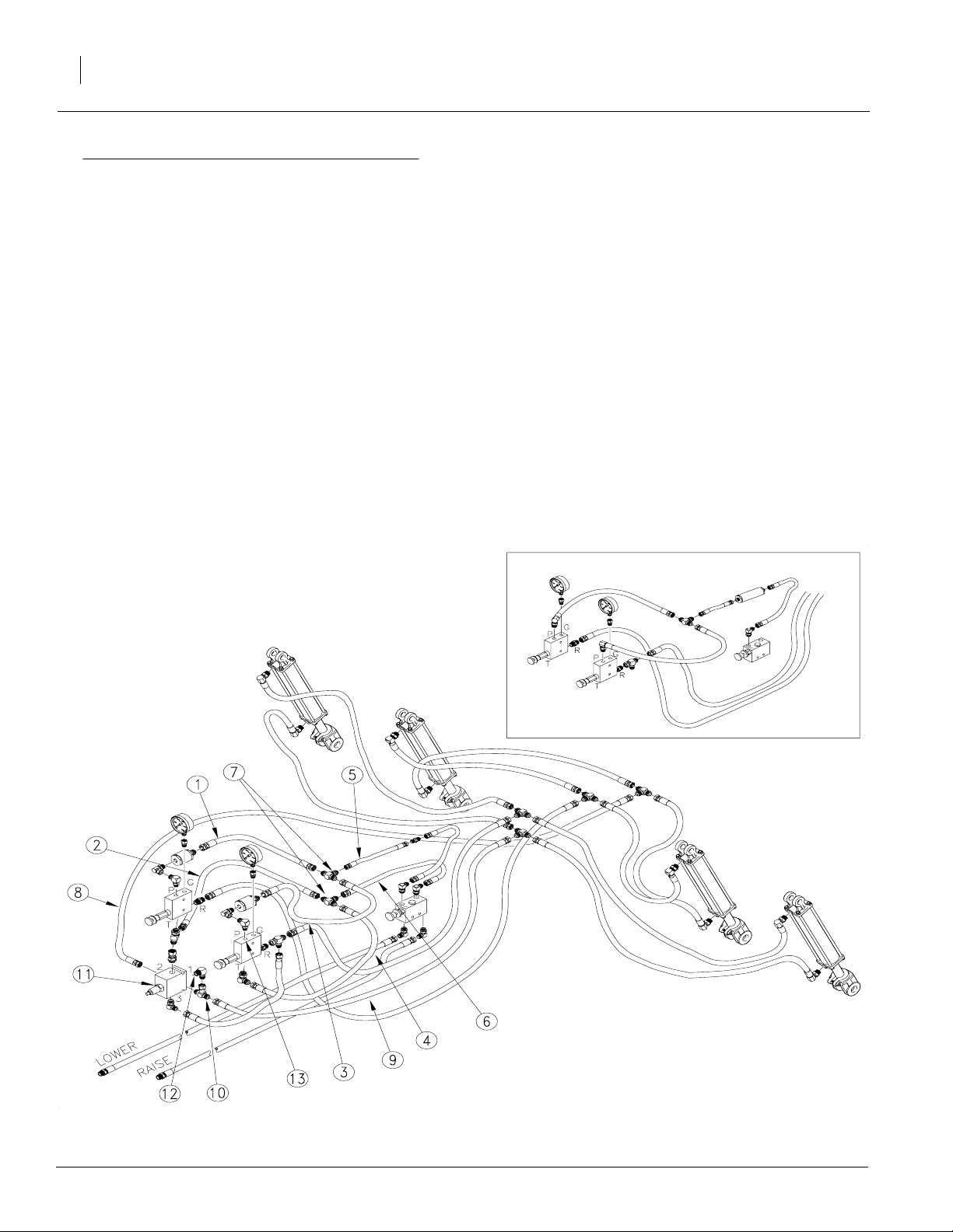
Refer to Figure 1
1. Removehoses(1),(2),(3),(4),(5) and (6) from
bulkhead tee fittings (7).
2. Removethebulkhead tee fittings (7)from the
drill, and discard.
3. Removehoses (8) and(9) from the tee fitting
(10) on counter balance valve (11).
4. Removethe teefitting(10)from CBV (10) and
discard.
5. Reinstall hose (8) on elbow fitting (12).
S/N DD1215- December 2004-
S/N 1216+ January 2005+
22624
Figure 1
Original Plumbing
195-300M 2/22/2005
Page 3
Great Plains Mfg., Inc.
Refer to Figure 2
6. Removethe mountingbolts for the LH Reducing Valve(13). Reinstall the bolts, placing six
flat washers (14) against the valve's body to
shim it away from the mounting bracket.
Installation Instructions
Figure 2
Shimming the Valve
3
22625
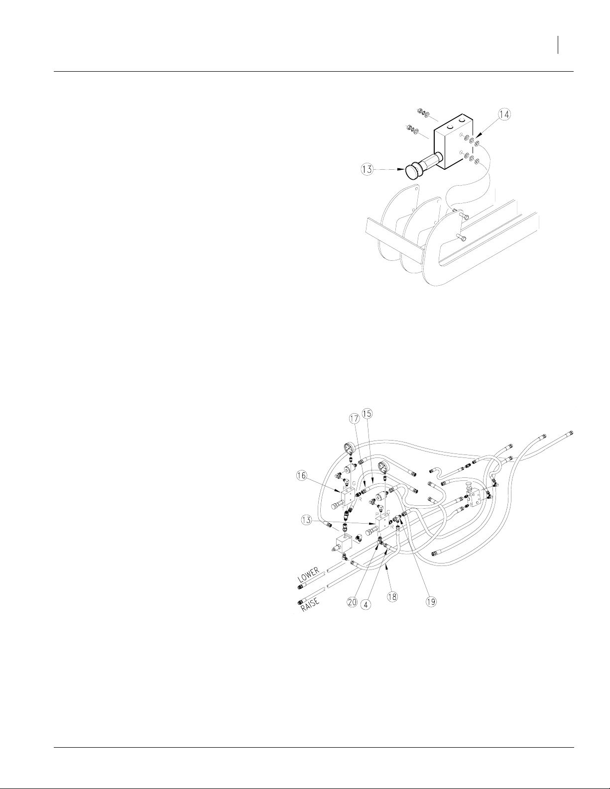
Refer to Figure 3
7. Removehose (15) from the back of the RH reducing valve (16). Install tee fitting (17) supplied with the kit.
8. Removehose (18) from the tee fitting (19)on
backof LHreducingvalve(13)and re-attachit
to tee fitting (17)on the backof theRH reducing valve (16).
9. Disconnect Hose (4) from elbow (20). Save
this hose for re-use. Remove and save elbow
(20) from the bottom ofthe LHreducing valve
(13).
22626
Figure 3
Removing Fittings
2/22/2005
195-300M
Page 4

Point Row Option
4
Refer to Figure 4
10. Assemble 9/16" x 3/4"elbows (21), from thekit,
to the ports V1, V2 of the block (22). Assemble
9/16" x 9/16" elbows(23), from the kit, to ports
A1, B1, A3 and B3. Install plugs (24), from the
kit, in ports A2, B2, V1 and V2.
Great Plains Mfg., Inc.
22627
Refer to Figure 5
11. Mount valve block (22) to the bracket as shown
using 3/8" x 3 3/4" bolts (25) as shown.
12. Place new decals (26) over the existing decals
to distinguish valves for the LH and RH wings.
Figure 4
Sub Assembly Solenoid Valve
22628
Figure 5
Installing Solenoid Valve
195-300M 2/22/2005
Page 5

Great Plains Mfg., Inc.
Refer to Figure 6
13. Install the LH Counterbalance valve (27) under the
LHreducingvalve(13)using fitting (28) andtee(29)
fromthekit.Besureto connect port2 on the CBV to
the T port on the reducing valve.
14. Connect supply hose (5)from the filterto the elbow
in port V1.Connectthe return hose(6) totheelbow
in port V2.
15. Connecthose(1)from the RH reducing valve(16) P
port to theelbow on portA1. Connect hose (3) from
the LH reducing valve (13) P port to the elbow in
port A3.
16. Connect returnhose (2) from the Tee in thebottom
of the RH reducing valve (16) to elbow in port B1.
Re-installreturn hose (4) from the Teeinthebottom
of the LH reducing valve (13) to the elbow on port
B3.
17. Install elbow (20), removed earlier and elbow
(30),from the kit, to ports 1 and 3 on
the LH CBV (27).
Installation Instructions
20. Isolate the LH and the RH wing opener lift cylinders
on the drill by switching hoses at the T fittings (34),
(35), (36) and (37) at therear ofthe mainframe. Connect rod-end hoses to rod-end hosesand base end
hoses to base end hoses.Keep the LH wing andRH
wing separate. Connect hoses going forward from
the T's as follows:
• RH cylinders, base end Tee (34) to RH reducing
valve R port Tee (32).
• LH cylinders, base end Tee (35) to LH reducing
valve R port Tee (33).
• RH cylinders, rod end Tee (36) to RH CBV port 1
elbow (38).
• LH cylinders, rod end Tee (37) to LH CBV port 1
elbow (30).
21. This finishes the hoserouting, tighten all fittingsand
hardware.
5
18. Connect the LH pilot line hose (31)
supplied with the kit, from elbow
(20) to Tee (19).
19. Connectelbows(32)and (33) from the
kit to Tees(17) and(19) on the backof
the reducing valves (13) and
(16).
2/22/2005
Figure 6
Final Plumbing
22629
195-300M
Page 6

Point Row Option
6
Refer to Figure 7
22. Remove the plug (39) on the bypass valve
block (40) and discard. Install the solenoid
valve(41) from the kit into this open port. Refer to the next step for special handling and
tightening instructions.
23. Thesolenoidvalve(41)needstobe tightened
into the valve block (40) to seat the oring. A
special thin wrench is required forthis. If a
special thin wrench is notavailable,do the following.
24. Carefully loosen the coil nut (42) ontop ofthe
solenoid(41). Removethe coilassembly(43).
The hex (44) on the lower part of the valve is
now exposed and a regular wrench may be
used to tighten the valve into the block.
Great Plains Mfg., Inc.
25. Reinstall the coil (43) and coil nut (42). Use
great care tonot over tighten this nut. Torque
to 4-6 lb-ft.
26. Route the wire harness through the tongue.
Connect the 3 weatherpak ends without dust
caps to the 3 solenoid valves on the large
valve block (22).
Note that the center solenoid is not used on this
drill, butcan be connected to keepdirt and water
out of the ends.
27. Remove the dust cap from the remaining
weatherpak end and connect it to the single
solenoid valve (41) in the bypass valve block
(40).
22637
Figure 7
Bypass Valve Solenoid Installation
195-300M 2/22/2005
Page 7

Great Plains Mfg., Inc.
ADJUSTING THE COUNTERBALANCE
VALVE(S).
On the stemof the valve (item 27,Figure 6) there
is a rubber cap that protects the threads of an adjustment stem. This stemislockedin place with a
hex nut. To adjust the valve, loosen the nutand
turn the stem using an Allen wrench.
Screwing the stem in (clockwise) pushes on a
spring which supplementsthe pilot line's forceon
an internal piston. More spring force will let the
valve open with a low pilot pressure. Less spring
forcewillrequire higher pilot pressure toopenthe
valve.
Note: With the screw turned infully,the springwill
developenough force on the pistonthat the valve
will unlock even with no pilot pressure. Theopeners will settle.
Raise and lower the drill several times then hold
hydraulicdown pressure on theopeners to purge
air from the system and to warm the oil. Repeat.
Installation Instructions
7
Raise the openers andreturn the lever to neutral.
Observe the openers closely to detect settling. If
the openers remain up, no valve adjustment is
needed.
If the openers settle,the stem is screwedin too
far. Gently back the stem out until it stops, then
screw it in one turn. Generallythis is agood starting point. Check for settling.
Backing the stem outwill lock the valve, screwing
it in too far can cause it to unlock.
A small increase in lowering speed can be
achievedby screwing the stem in.
2/22/2005
195-300M
Page 8

Great Plains Mfg., Inc.
195-299A 2S-2600 Point Ro w ACC 2004 CBV
Your kit includes:
Qty. Part No. Part Description
1 195-300M MANUAL 2600 PNTROW INSTALL
6 800-082C CABLE TIE .31X21.5 6DIA 120LB
2 802-026C HHCS 3/8-16X3 3/4 GR5
2 803-014C NUT HEX 3/8-16 PLT
2 804-013C WASHER LOCK SPRING 3/8 PLT
6 804-007C WASHER FLAT 1/4 SAE PLT
1 810-371C MANIFOLD ASY 3S-3000 POINT ROW
1 810-408C BYPASS CARTRIDGE AND SOLENOID
1 810-523C VALVE COUNTER BAL 10:1 9/16FOB
1 811-061C TEE 9/16MJIC 9/16MJIC 9/16MORB
2 811-069C EL 9/16MJIC 9/16FJIC
1 811-064C TEE 9/16MJIC 9/16MJIC 9/16MORB
5 811-065C EL 9/16MJIC 9/16MORB
2 811-171C EL 3/4MORB 9/16MJIC
2 811-203C PL 3/4MORB HOLLOW HEX
1 811-627C AD 9/16MORB 9/16FJIC
1 811-631C HH3/8R1 018 9/16FJIC
2 811-757C PL 9/16MORB HOLLOW HEX
1 818-662C DECAL RIGHT SECTION
1 818-663C DECAL LEFT SECTION
1 823-175C 3 SECT POINT ROW WIRE HARNESS
1 823-185C POINT ROW CONTROL BOX
1 823-190C POINT ROW CABLE W/ POWER LEAD
Installation Instructions
8
195-300M2/22/2005
 Loading...