

Page 1
Operator’ s Manual
2N-2410 and 2N-3010
Folding No-Till Drill
Manufacturing, Inc.
www .g reatplainsmfg.com
Read the operator’s manual entirely. When you see this symbol, the subsequent in-
!
structions and warnings are serious -follow without exception. Your life andthelives of
others depend on it!
© Copyright 1999 Printed
7/27/2005
14570
Cover illustration may show optional equipment not supplied with standard unit.
196-126M
Page 2

Table of Contents
Table of Contents
Great Plains Mfg., Inc.
Important Safety Information . . . . . . . . . . . . . . . . . . 1
Introduction . . . . . . . . . . . . . . . . . . . . . . . . . . . . . . . . 9
Description of Unit . . . . . . . . . . . . . . . . . . . . . . . . 9
Intended Usage. . . . . . . . . . . . . . . . . . . . . . . . . . . 9
Using This Manual. . . . . . . . . . . . . . . . . . . . . . . . . 9
Definitions . . . . . . . . . . . . . . . . . . . . . . . . . . . . 9
Owner Assistance . . . . . . . . . . . . . . . . . . . . . . . . . 9
Section 1 Drill Preparation and Setup . . . . . . . . . . 10
Prestart Checklist . . . . . . . . . . . . . . . . . . . . . . . . 10
Hitch Height Adjustment . . . . . . . . . . . . . . . . . . . 10
Installing Drill Control Consoles. . . . . . . . . . . . . . 11
Bleeding Hydraulic Systems . . . . . . . . . . . . . . . . 11
Field-Lift Hydraulics. . . . . . . . . . . . . . . . . . . . 11
Transport-Lock Hydraulics. . . . . . . . . . . . . . . 11
Raise-To-Fold Hydraulics . . . . . . . . . . . . . . . 12
Fold Hydraulics . . . . . . . . . . . . . . . . . . . . . . . 12
Marker Hydraulics. . . . . . . . . . . . . . . . . . . . . 13
Frame Leveling Adjustment . . . . . . . . . . . . . . . . . 13
Aligning Boxes. . . . . . . . . . . . . . . . . . . . . . . . . . . 14
Section 2 Operating Instructions 15
Prestart Checklist . . . . . . . . . . . . . . . . . . . . . . . . 15
Tractor Requirements . . . . . . . . . . . . . . . . . . . . . 15
Recommended Minimum Tractor Size . . . . . 15
Minimum Towing Vehicle Weight. . . . . . . . . . 15
Hydrualics . . . . . . . . . . . . . . . . . . . . . . . . . . . 15
Safety Lights . . . . . . . . . . . . . . . . . . . . . . . . . 15
Hitching Tractor to Drill . . . . . . . . . . . . . . . . . . . . 15
Operating Control Console . . . . . . . . . . . . . . . . . 16
Operating Electric Clutch Consoles. . . . . . . . . . . 16
Folding the Drill . . . . . . . . . . . . . . . . . . . . . . . . . . 16
Folding Harrow Attachment. . . . . . . . . . . . . . 16
Unfolding the Drill . . . . . . . . . . . . . . . . . . . . . . . . 16
Lifting the Drill in the Field. . . . . . . . . . . . . . . . . . 17
Field Operations . . . . . . . . . . . . . . . . . . . . . . . . . 17
Opener Operation . . . . . . . . . . . . . . . . . . . . . 17
Marker Operation . . . . . . . . . . . . . . . . . . . . . 17
Shaft Monitor Operation . . . . . . . . . . . . . . . . 18
Electric Clutch Operation . . . . . . . . . . . . . . . 18
Transporting. . . . . . . . . . . . . . . . . . . . . . . . . . . . . 18
Parking . . . . . . . . . . . . . . . . . . . . . . . . . . . . . . . . 18
Section 3 Adjustments . . . . . . . . . . . . . . . . . . . . . . 19
No-Till Seeding . . . . . . . . . . . . . . . . . . . . . . . . . . 19
Coulter Adjustments . . . . . . . . . . . . . . . . . . . . . . 19
Hydraulic Depth Control . . . . . . . . . . . . . . . . . . . 19
Electric Clutch Switch Adjustment . . . . . . . . . . . 20
Weights. . . . . . . . . . . . . . . . . . . . . . . . . . . . . . . . 21
Coulter Springs. . . . . . . . . . . . . . . . . . . . . . . . . . 21
Individual Coulters . . . . . . . . . . . . . . . . . . . . 21
Opener Down-Pressure Adjustment. . . . . . . . . . 22
Press Wheel Adjustment . . . . . . . . . . . . . . . . . . 22
Setting the Seeding Rate . . . . . . . . . . . . . . . . . . 22
Small Seeds Attachment . . . . . . . . . . . . . . . . . . . 23
Seed Rate Charts. . . . . . . . . . . . . . . . . . . . . . . . . 24
Small Seeds Attachment Seed Rate Chart . . . . .32
Gauge-Wheel Drive Adjustment. . . . . . . . . . . . . 34
Disk Scraper Adjustment . . . . . . . . . . . . . . . . . . 34
Leveling Adjustment. . . . . . . . . . . . . . . . . . . . . . 34
Marker Adjustments . . . . . . . . . . . . . . . . . . . . . . 34
Marker Chain . . . . . . . . . . . . . . . . . . . . . . . . 34
Disk Adjustment. . . . . . . . . . . . . . . . . . . . . . 35
Folding Speed . . . . . . . . . . . . . . . . . . . . . . . 35
Coulter Tines . . . . . . . . . . . . . . . . . . . . . . . . . . . 36
Harrow Attachment Adjustment . . . . . . . . . . . . . 36
Seed-Lok . . . . . . . . . . . . . . . . . . . . . . . . . . . . . . 36
Section 4 Troubleshooting. . . . . . . . . . . . . . . . . . . 37
Section 5 Maintenance and Lubrication. . . . . . . . 40
General Maintenance. . . . . . . . . . . . . . . . . . . . . 40
Storage. . . . . . . . . . . . . . . . . . . . . . . . . . . . . . . . 40
Lubrication . . . . . . . . . . . . . . . . . . . . . . . . . . . . . 41
Section 6 Options . . . . . . . . . . . . . . . . . . . . . . . . . . 45
Coulter Tines . . . . . . . . . . . . . . . . . . . . . . . . . . . 45
Weight Brackets . . . . . . . . . . . . . . . . . . . . . . . . . 45
Shaft Monitors . . . . . . . . . . . . . . . . . . . . . . . . . . 45
Markers. . . . . . . . . . . . . . . . . . . . . . . . . . . . . . . . 46
Small Seeds Attachment . . . . . . . . . . . . . . . . . . 46
Rear Mount Boom . . . . . . . . . . . . . . . . . . . . . . . 47
Harrow Attachment. . . . . . . . . . . . . . . . . . . . . . . 47
Seed Box Agitator. . . . . . . . . . . . . . . . . . . . . . . . 48
Seed-Lok Firming Wheels . . . . . . . . . . . . . . . . . 48
Seed-Cup Plugs . . . . . . . . . . . . . . . . . . . . . . . . . 48
Section 7 Specifications and Capacities . . . . . . . 49
Appendix . . . . . . . . . . . . . . . . . . . . . . . . . . . . . . . . . 50
Tire Inflation Chart . . . . . . . . . . . . . . . . . . . . . . . 50
Torque Values Chart for Common Bolt Sizes. . . 50
Electric Clutch and Wire Harness Diagram . . . . .51
Warranty. . . . . . . . . . . . . . . . . . . . . . . . . . . . . . . 53
© Copyright 1999 All rights Reserved
Great PlainsManufacturing, Inc. providesthis publication“as is” withoutwarr antyof anykind,either expressedor implied. Whilee v eryprecaution has beentaken in thepreparation
of thismanual, GreatPlains Manufacturing,Inc. assumes noresponsibility forerrors oromissions.Neither isany liabilityassumed fordamages resulting fromthe useofthe information contained herein. GreatPlainsManufacturing, Inc. reserves the right to reviseand improve its products as it seesfit. This publication describes the state of this productat the
time ofits publication, and maynot reflect theproductin the future.
The followingare trademarks ofGreatPlains Mfg., Inc.: ApplicationSystems, Ausherman, LandPride, GreatPlains, Seed-Lok
All otherbrands and product namesare trademarks or registeredtrademarksof their respectiveholders.
2N-2410 and 2N-3010 Folding No-Till Drill 196-126M 12/27/05
Great PlainsManufacturing, Incorporated Trademarks
Printed in the United StatesofAmerica.
Page 3
Great Plains Mfg., Inc.
Important Safety Information
Important Safety Information
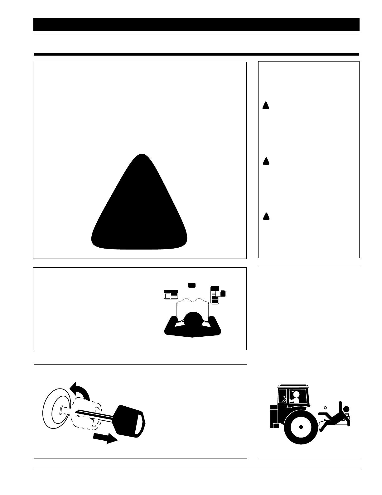
Look for Safety Symbol
The SAFETY ALERT SYMBOL indicates there is a potential hazard to
personal safety involved and extra
safety precaution must be taken.
When you see this symbol, be alert
and carefully read the message that
follows it. In addition to design and
configuration of equipment, hazard
control and accident prevention are
dependent upon the awareness,concern, prudence and proper training of
personnel involved in the operation,
transport, maintenance and storage
of equipment.
!
Be Aware of Signal Words
Signal words designate a degree or
level of hazard seriousness. The signal words are:
!
DANGER!
Indicates an imminently hazardous
situation which, if not avoided, will
result in death or serious injury. This
signal word is limited to the most
extreme situations, typically for
machine components that, for functional purposes, cannot be guarded.
!
WARNING!
Indicates a potentially hazardous situation which, if not avoided, could
result in death or serious injury, and
includes hazards that are exposed
when guards are removed. It may
also be used to alert against unsafe
practices.
CAUTION!
!
Indicates a potentially hazardous situation which, if not avoided, may
result in minor or moderate injury. It
may also be used to alert against
unsafe practices.
For Your Protection
▲ Thoroughly read and understand
Safety Labels, page 5.
▲ Read all instructions noted on the
labels.
OFF
Keep Riders
Off Machinery
▲ Riders obstruct the operator’s
view. They could be struck by foreign objects or thrown from the
machine.
▲ Never allow children to operate
equipment.
Shutdown and Storage
▲ Lower machine to ground, put
tractor in park, turn off engine,
and remove the key.
▲ Detach and store implements in a
area where children normally do
not play. Secure implement by
using blocks and supports.
12/27/05
2N-2410 and 2N-3010 Folding No-Till Drill 196-126M
1
Page 4
Important Safety Information
Great Plains Mfg., Inc.
Use Safety
Lights and Devices
▲ Slow moving tractors, self-pro-
pelled equipment, and towed
implements can create a hazard
when driven on public roads. They
are difficult to see, especially at
night.
▲ Flashing warning lights and turn
signals are recommended whenever driving on public roads. Use
lights and devices provided with
implement.
Transport Machinery Safely
▲ Comply with state and local laws.
▲ Maximum transport speed for imple-
ment is 20 mph. DO NOT EXCEED.
Never travel at a speed which does
not allow adequate control of steering and stopping. Some rough terrains require a slower speed.
▲ Sudden braking can cause a towed
load to swerve and upset. Reduce
speed if towed load is not equipped
with brakes.
▲ Use the following maximum speed
guidelines:
20 mph when weight is less than
or equal to the weight of tractor.
10 mph when weight is double
the weight of tractor.
IMPORTANT: Do not tow a load that is
more than double the weight of tractor.
Use A Safety Chain
▲ A safety chain will help control
drawn machinery should it separate from the tractor drawbar.
▲ Use a chain with the strength
rating equal to or greater than
the gross weight of the towed
machinery.
▲ Attach the chain to the tractor
drawbar support or other specified anchor location. Allow only
enough slack in the chain to permit turning.
▲ Do not use safety chain for tow-
ing.
Practice Safe Maintenance
▲ Understand procedure before doing
work. Use proper tools and equipment. Refer to this manual for additional information.
▲ Work in a clean, dry area.
▲ Lower the implement to the ground,
put tractor in park, turn off engine,
and remove key before performing
maintenance.
▲ Allow implement to cool completely.
▲ Install all transport locks on raised drill
before working underneath. Refer to
the Folding the Drill,“Operating
Instructions,” page 16, for instructions
on engaging the transport locks.
▲ Do not grease or oil implement while
it is in operation.
▲ Disk edges are sharp. Be careful
when working in this area.
▲ Disconnect battery ground cable (-)
before servicing or adjusting electrical systems or before welding on
implement.
▲ Inspect all parts. Make sure parts
are in good condition and installed
properly.
▲ Remove buildup of grease, oil or
debris.
▲ Remove all tools and unused parts
from implement before operation.
2N-2410 and 2N-3010 Folding No-Till Drill 196-126M 12/27/05
2
Page 5
Great Plains Mfg., Inc.
Important Safety Information
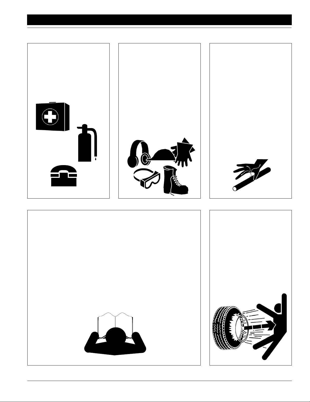
Prepare for Emergencies
▲ Be prepared if a fire starts.
▲ Keep a first aid kit and fire extin-
guisher handy.
▲ Keep emergency numbers for
doctor, ambulance, hospital and
fire department near phone.
911
Wear
Protective Equipment
▲ Wear protective clothing and
equipment.
▲ Wear clothing and equipment
appropriate for the job. Avoid
loose-fitting clothing.
▲ Prolonged exposure to loud noise
can cause hearing impairment or
hearing loss. Wear suitable hearing protection such as earmuffs or
earplugs.
▲ Operating equipment safely
requires the full attention of the
operator. Avoid wearing radio
headphones while operating
machinery.
Avoid High
Pressure Fluids Hazard
▲ Escaping fluid under pressure can
penetrate the skin causing serious
injury.
▲ Avoid the hazard by relieving
pressure before disconnecting
hydraulic lines.
▲ Use a piece of paper or card-
board, NOT BODY PARTS, to
check for suspected leaks.
▲ Wear protective gloves and safety
glasses or goggles when working
with hydraulic systems.
▲ If an accident occurs, see a doc-
tor immediately. Any fluid injected
into the skin must be surgically
removed within a few hours or
gangrene may result.
Safety at All Times
Thoroughly read and understand the
instructions given in this manual before
operation. Refer to the Safety Labels,
page 5. Read all instructions noted on
the labels.
▲ Operator should be familiar with all
functions of the unit.
▲ Operate implement from the driver’s
seat only.
▲ Do not leave tractor or implement
unattended with engine running.
▲ Dismounting from a moving tractor
could cause serious injury or death.
▲ Do not stand between the tractor
and implement during hitching.
▲ Keep hands, feet and clothing away
from power-driven parts.
▲ Wear snug-fitting clothing to avoid
entanglement with moving parts.
▲ Watch out for wires, trees, etc.,
when folding and raising implement.
Make sure all persons are clear of
working area.
▲ Turning tractor too tight may cause
implement to ride up on wheels.
This could result in injury or equipment damage.
Tire Safety
▲ Tire changing can be dangerous
and should be performed by
trained personnel using the correct tools and equipment.
▲ When inflating tires, use a clip-on
chuck and extension hose long
enough to allow you to stand to
one side and NOT in front of or
over the tire assembly. Use a
safety cage if available.
▲ When removing and installing
wheels, use wheel-handling
equipment adequate for the
weight involved.
12/27/05
2N-2410 and 2N-3010 Folding No-Till Drill 196-126M
3
Page 6

Important Safety Information
Great Plains Mfg., Inc.
Handle
Chemicals Properly
▲ Read and follow chemical manu-
facturer’s instructions.
▲ Wear protective clothing.
▲ Handle all chemicals with care.
▲ Agricultural chemicals can be
dangerous. Improper use can
seriously injure persons, animals,
plants, soil and property.
▲ Inhaling smoke from any type of
chemical fire is a serious health
hazard.
▲ Store or dispose of unused chem-
icals as specified by the chemical
manufacturer.
▲ Before adding chemical to the
tank, make sure tank is at least
half full. Do not pour concentrate
into an empty tank.
▲ Never leave fill hose attached to
the sprayer after filling tank.
Chemicals in tank can siphon out
of tank and contaminate freshwater source.
▲ Always keep clean water and
soap available in case of an emergency. Immediately and thoroughly flush any area of the body
that is contaminated by chemicals.
▲ Do not touch boom components
with mouth or lips.
▲ If chemical is swallowed, carefully
follow the chemical manufacturer’s recommendations and consult with a doctor.
▲ If persons are exposed to a chem-
ical in a way that could affect their
health, consult a doctor immediately with the chemical label or
container in hand. Any delay
could cause serious illness or
death.
▲ Dispose of empty chemical con-
tainers properly. By law rinsing of
the used chemical container must
be repeated three times. Puncture
the container to prevent future
use. An alternative is to jet-rinse
or pressure rinse the container.
▲ Wash hands and face before eat-
ing after working with chemicals.
Shower as soon as spraying is
completed for the day.
▲ Spray only with acceptable wind
conditions. Wind speed must be
below 5 mph. Make sure wind drift
of chemicals will not affect any
surrounding land, people or animals.
▲ Never wash out the sprayer tank
within 100 feet of any freshwater
source or in a car wash.
▲ Rinse out sprayer tank. Spray rinse
water on last field sprayed.
Personal Safety Equipment
Great Plains advises all users of chemical pesticides or
herbicides to use the following personal safety equipment. Always follow the chemical label instructions.
Operator safety and the effectivity of the product
depends upon operator actions.
▲ Waterproof, wide-brimmed hat
▲ Waterproof apron
▲ Face shield, goggles or full face
respirator. Goggles with side
shields or a full face respirator is
required if handling or applying
dusts, wettable powders, or granules or if being exposed to spray
mist.
▲ Cartridge-type respirator
approved for pesticide vapors
unless label specifies another
type of respirator.
▲ Waterproof, unlined gloves. Neo-
prene gloves are recommended.
▲ Cloth coveralls/outer clothing
changed daily; waterproof items
if there is a chance of becoming
wet with spray
▲ Waterproof boots or foot cover-
ings
2N-2410 and 2N-3010 Folding No-Till Drill 196-126M 12/27/05
4
Page 7
Great Plains Mfg., Inc.
Important Safety Information
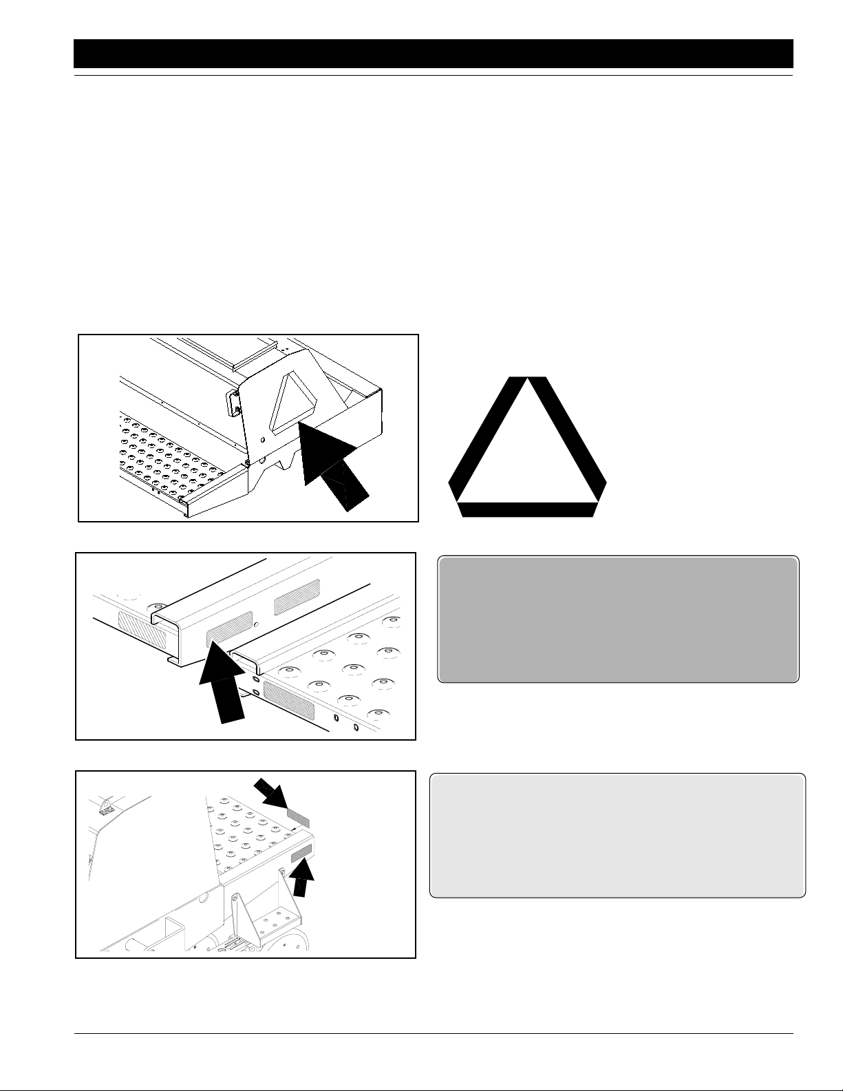
Safety Labels
Your implement comes equipped with all safety labels in place.
They were designed to help you safely operate your implement.
1. Read and follow label directions.
2. Keep all safety labels clean and legible.
3. Replace all damaged or missing labels. Order new labels
from your Great Plains dealer. Refer to this section for
proper label placement.
4. When ordering new parts or components, also request corresponding safety labels.
5. To install new labels:
a. Clean the area on which the label is to be placed.
b. Peel backing from label. Press firmly on surface,
being careful not to cause air bubbles under label.
12945
12942
818-003C
Slow Moving Vehicle
838-266C
Red Reflector
12/27/05
12943
838-265C
Amber Reflectors
2N-2410 and 2N-3010 Folding No-Till Drill 196-126M
5
Page 8
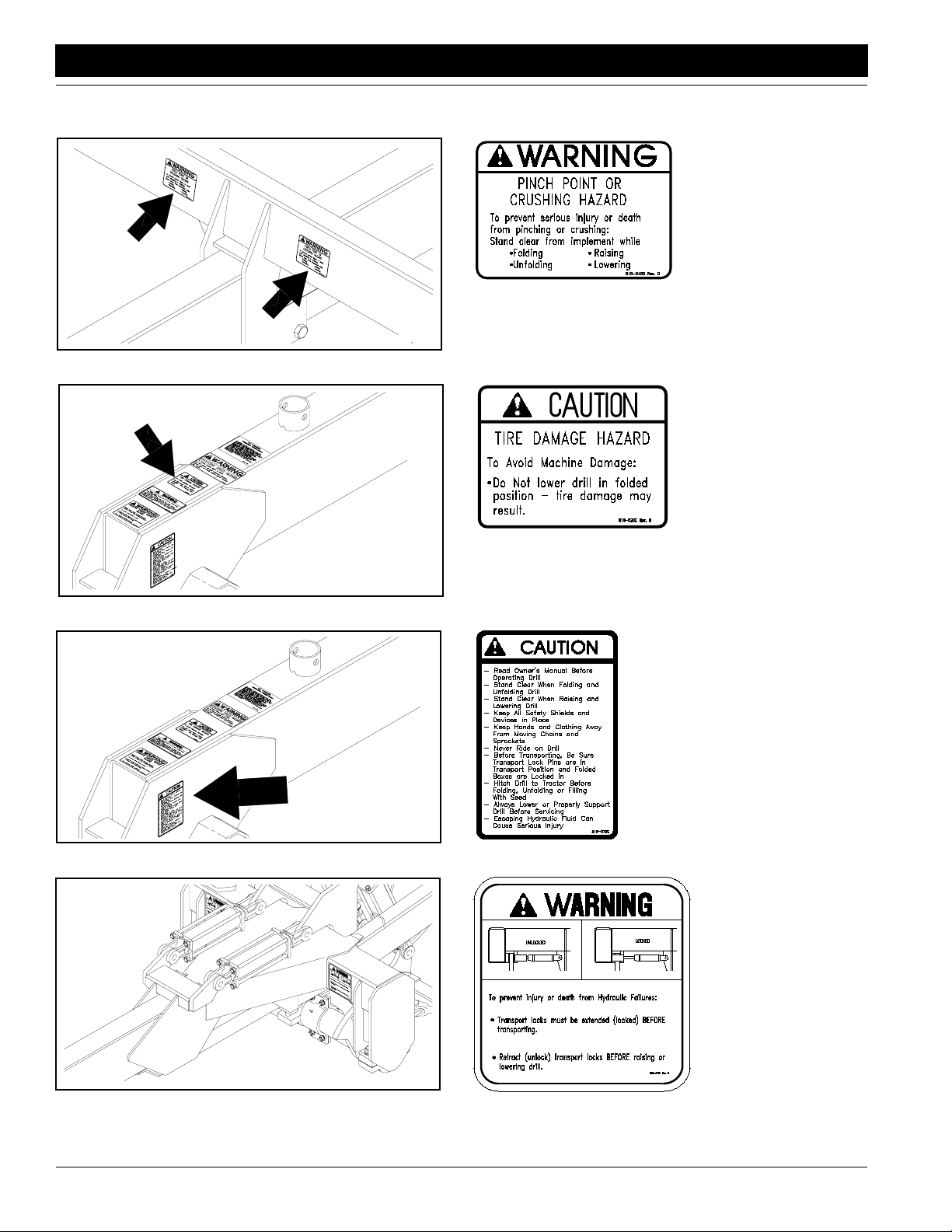
Important Safety Information
Great Plains Mfg., Inc.
12941
12944
818-045C
Warning Folding-Raising
818-020C
Caution Lowering Drill
818-078C
12950
General Caution
818-477C
Warning Transport
14526
2N-2410 and 2N-3010 Folding No-Till Drill 196-126M 12/27/05
6
Lock
Page 9

Great Plains Mfg., Inc.
Important Safety Information
12950
818-188C
20 MPH Transport
12950
12950
818-019C
Negative Tongue Weight
818-475C/818-476C
Warning 30-Ft./24-Ft. Tongue Weight
12/27/05
13317
818-398C
Caution! Tires - Not a Step
2N-2410 and 2N-3010 Folding No-Till Drill 196-126M
7
Page 10
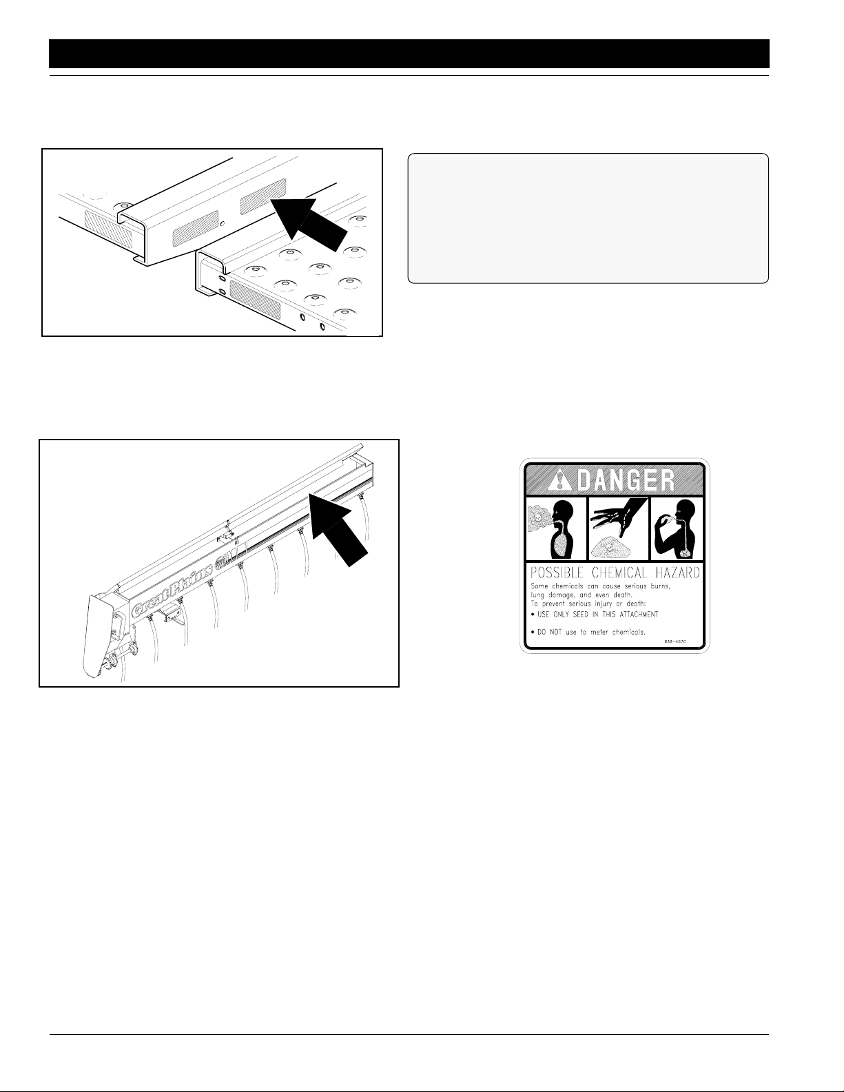
Important Safety Information
12942
Great Plains Mfg., Inc.
838-267C
Daytime Reflector
13734
2N-2410 and 2N-3010 Folding No-Till Drill 196-126M 12/27/05
8
838-467C
Possible Chemical Hazard
Page 11
Great Plains Mfg., Inc.
Introduction
Introduction
Great Plains welcomes you to its growing family of new
product owners. This implement has been designed with
care and built by skilled workers using quality materials.
Proper assembly, maintenance and safe operating practices will help you get years of satisfactory use from the
machine.
Description of Unit
The two-section folding no-till drill is a towed seeding implement for no- or minimum-till soil conditions. The drill is
equipped with two hydraulic circuits. One is used to raise
and lower the drill for field operations. A separate electrohydraulic circuit lifts, locks and folds the implement for
transport. An in-cab control console allowstheoperatorto
switch between functions on the electro-hydraulic circuit.
Thedrillisoutfittedwithcoultersanddouble-diskopeners.
The openers are mounted on parallel arms. Press wheels
follow the opener disks to firm the seedbed and control
seeding depth.
Intended Usage
This machine is intended foruse in minimum- or no-till applications.
Using This Manual
This manual will familiarize you with safety, assembly, operation, adjustment, troubleshooting and maintenance.
Readthismanualandfollow the recommendations to help
ensure safe and efficient operation.
Fill out the warranty sheet with the dealer at the time of
purchase. Give the dealer the completed white copy and
send the pink copy to Great Plains.Keepyouryellowcopy
in the manual for use when corresponding with thedealer.
Thismanualiscurrent at printing. Someparts maychange
to assure top performance.
Definitions
Right and left as used in this manual are determined by
facingthe direction the machine will travelwhile in use unless otherwise stated.
IMPORTANT: A crucial point of information related to
the preceding topic. For safe and correct oper ation,
read and follow the directions provided before continuing.
Owner Assistance
If customer service or repair parts are needed contact
your Great Plains dealer. They have trained personnel,
parts and service equipment specially designed for Great
Plains products.
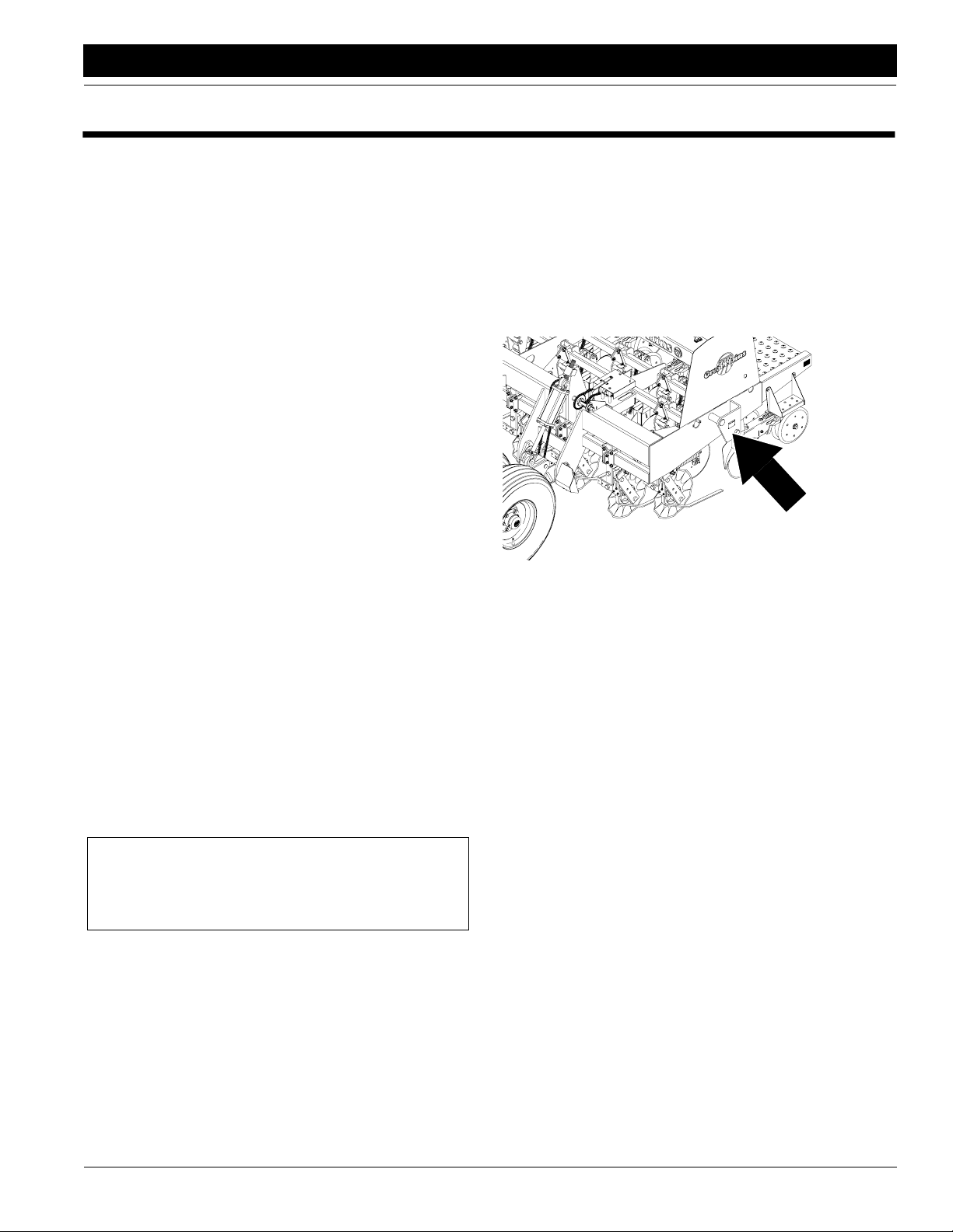
Your machine’sparts were specially designed and should
only be replaced with Great Plains parts. Always use the
serial and model number when ordering parts from your
Great Plains dealer. The serial number plate is located on
the outside end of the left drill box as shown in Figure A.
16537
Figure A
Serial Number Plate
Your Great Plains dealer wants you to be satisfied with
your new machine. If you do not understand any part of
this manual or are not satisfied with the service received,
please take the following actions:
1. Discuss the matter with your dealer service manager.
Makesurethey areawareofany problemssotheycan
assist you.
2. If you are still not satisfied, seek out the dealership
owner or general manager.
3. For further assistance, write to:
Product Support
Great Plains Mfg. Inc.
Service Department
P.O. Box 5060
Salina, KS 67402-5060
NOTE: Useful information related to the preceding topic.
12/27/05
2N-2410 and 2N-3010 Folding No-Till Drill 196-126M
9
Page 12
Section 1 Drill Preparation and Setup
Section 1 Drill Preparation and Setup
Great Plains Mfg., Inc.
This section will help you prepare your tractor and drill for
use. The drill hitch must be adjusted to match drawbar
height, and the drill control console must be installed in
your tractor.
This section also covers bleeding the drill hydraulics and
making drill frame and box adjustments. As the operator,
you may need to perform these functions after dill repair.
Beforeoperatingthe drill, checkthatthehydraulic systems
are free or air, the frame is level, and boxes are aligned.
Prestart Checklist
1. Read and understand “Important Safety Information,” page 1.
2. Check that all working parts are moving freely, bolts
are tight, and cotter pins are spread.
3. Check that all grease fittings are in place and lubricated. Refer to Lubrication,“Maintenance and Lubrica-
tion,” page 41.
4. Checkthatallsafety labels and reflectorsarecorrectly
located and legible. Replace if damaged. See Safety
Labels,“Important Safety Information,”page 5.
5. Inflate tires to pressure recommended and tighten
wheel bolts as specified. See “Appendix,” page 50.
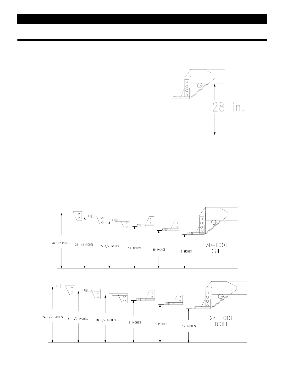
Hitch Height Adjustment
For proper operation, the drill tongue must run parallel to
the ground in field position. Follow these instructions to
adjust the drill hitch to match your tractor drawbar height.
1. Check the distance from under the tongue to the
groundasshowninFigure1-1.Using the drill jack, adjust the tongue up or down until the distance is about
28 inches.
16273
Figure 1-1
Tongue Height
2. Back the tractor drawbar up to the drill hitch. Determine how much adjustment is needed for the drill to
match drawbar height.
3. Unbolt the hitch from the tongue. Rebolt the hitch so
thedrillmatchesdrawbar height.Keepingin mind your
drill size, refer to Figure 1-2 or Figure 1-3 for the different ways you can bolt the hitch and the resulting hitch
heights.
16532
Hitch Height Adjustment, 30-Foot Drills
16274
Hitch Height Adjustment, 24-Foot Drills
2N-2410 and 2N-3010 Folding No-Till Drill 196-126M 12/27/05
10
Figure 1-2
Figure 1-3
Page 13

Great Plains Mfg., Inc.
Section 1 Drill Preparation and Setup
4. Hitch the drill to the tractor using a hitch pin at least
one inch in diameter. Install a retaining clip on the
hitch pin to prevent it from working up.
NOTE:A clevis-style hitch, Great Plains part number 196136H, is available through your Great Plains dealer.
IMPORTANT: When hitching the drill to a different tractor,check for differencesin drawbar heights and re-adjust the drill hitch accordingly.
Installing Drill Control Consoles
1. Mountthecontrolboxes ataconvenientlocation in the
tractorcab.Connect the 12-footextensioncable to the
pin connector on the back of the control box. Route
thecabletothe tractordrawbararea.Secure the cable
to avoiddamage.
2. Connectthepowercordstoa12-voltpowersource on
the tractor.Thepolarity of the powersupply is very important. The red wire must be connected to the positive (+) battery terminal. The white wire must be
connected to the negative (-) battery terminal.
Note: To help with console and wire harness installation
refer to diagram on page 46.
Bleeding Hydraulic Systems
A hydraulic system with air in the circuit will movein jerky,
unevenmotions.Ifyourhydraulics havenotbeenproperly
bled or you replace a hydraulic component, bleed the hydraulics.
Field-Lift Hydraulics
The field-lift system is equipped with four rephasing-type
hydraulic cylinders that require a special procedure for
bleeding air. Read and follow the procedure carefully.Air
in the system will cause uneven seeding across the drill.
Do not loosen hose fittings in order to bleed air from this
system.
!
WARNING!
Escaping fluid under pressure can have sufficient pressure to
penetrate the skin causing serious injury. Avoid the hazard by
relieving pressure before disconnecting hydraulic lines. Use a
piece of paper or cardboard, NOT BODY PARTS, to check for
leaks. Wear protective gloves and safety glasses or goggles
whenworkingwithhydraulic systems. If anaccidentoccurs,see
a doctor immediately. Any fluid injected into the skin must be
surgically removed within a few hours or gangrene will result.
!
CAUTION!
This drill has a negative tongue weight when unfolded and
raised. Be certain that the drill is hitched securely to your tractor drawbar and the hitch safety chain is securely attached to
the drill.
!
WARNING!
Never allow anyone under the drill when fittings are opened.
Escaping fluid may allow the drill to drop suddenly.
1. Check that the tractor reservoir is filled to the proper
level.It will take 4 gallons to charge the field-lift cylinders.
2. Put the tractor in park and set the parking brake. If
your tractor does not have these features, block
wheels to prevent tractor from rolling.
3. Raiseandsupportthemainframeand outside endsof
boxesjust high enough to take the weight off all four
field-lift cylinders.
4. With the drill blocked and supported, unpin both ends
of all four field-lift cylinders. The field-lift cylinders are
locatedonthewinggauge wheels andthemain-frame
transport wheels. Remove and safely position the cylinders so the rod ends are higher than the base ends.
Check that there is enough room forthe cylinder rods
to fully extend without contacting anything.
IMPORTANT: To prevent trapped air poc kets, the rod
end must be higher than any other part of the cylinder.
5. Withthetractoratidle,engage the lift-hydraulicslever.
When the cylinders for both gauge wheels have completely extended, hold the leveron for one minute.
6. Retract the cylinder rods. Extend the rods again and
hold the lever on for one more minute. Repeat this
step two more times to completely bleed the system.
7. Retract and reattach the hydraulic cylinders.
8. Recheck the tractor hydraulic reservoir level and add
clean fluid as necessary.
Transport-Lock Hydraulics
The transport-lock cylinders are not rephasing. The two
transport-lock cylinders are on each side of the main
frame above the transport axle pivot tubes. Follow these
steps to properly bleed the transport-lock hydraulics.
1. Check that the tractor reservoir is filled to the proper
level.It will take about one gallon to charge the transport-lock cylinders.
2. Raise the drill to field position and support the main
frame.
3. Select the locks system on the control console. Retract the lock cylinders completely.
4. Loosen the connection between the hose and baseend tee fitting on the left lockcylinder.With the tractor
at idle slowly work the remote leverto feed oil to the
base end of the lock cylinders. Stop when you see oil
coming from around the fitting. Do not attempt to fully
extend the lock cylinders when bleeding the base
ends.
12/27/05
2N-2410 and 2N-3010 Folding No-Till Drill 196-126M
11
Page 14

Section 1 Drill Preparation and Setup
Great Plains Mfg., Inc.
5. With the cylinders completely extended, repeat step 4
for the rod-end fitting.
6. Recheck the tractor reservoir and add clean fluid as
necessary.
7. Retract and extendthe lock cylinders several times to
expelmost air from the system. The remaining air will
be expelled gradually during day-to-dayoperations.
8. Recheckthe tractor hydraulic reservoir and addclean
fluid as necessary.
Raise-To-Fold Hydraulics
The raise-to-foldcylinders are double acting but not
rephasing.Therearefourcylindersintheraise-to-foldsystem. Two are on the tool bar,and two are on the tongue.
Follow these steps to properly bleed the raise-to-fold hydraulics.
1. Check that the tractor reservoir is filled to the proper
level.Itwill take 3.4 gallons to charge the raise-to-fold
cylinders.
2. Select the raise-to-foldsystem on the control console.
3. Check that the drill is unfolded and resting safely on
the ground.
4. Disconnect the rod-end clevis of both tool-bar cylinders and both tongue cylinders. Support the cylinders
so the rods may extend and retract freely.
5. Retract the tongue cylinders completely. This will also
fully extend the tool-bar cylinders.
6. Loosen the hose-end fitting coming into the teeonthe
base end of the left tongue cylinder.
11. Slowly work the lever in the opposite direction to feed
oil to rod end of the tongue cylinders. Stop when you
see oil coming from around the fitting. Do not attempt
to retract the tongue cylinders while bleeding the rod
ends.
12. Loosen the hose-end fittings at the tee coming from
the base ends of the tool-bar cylinders. Slowly work
the lever to feed oil to the base end of the tool-bar cylinders.Stopwhenyouseeoilcomingfrom around the
fittings.Donotattempttoextend the tool-bar cylinders
while bleeding the base ends.
13. Extendandretractthecylindersseveral timestoexpel
most air from the system. The remaining air will gradually be pushed to the tractor during day-to-dayoperations.
14. Repin the tongue and tool-bar cylinders. Raise and
lower the wings several times to check for proper operation. If movementis erratic, repeat bleeding operation.
15. Recheck the tractor hydraulic reservoir level and add
clean fluid as necessary.
Fold Hydraulics
The fold cylinders are not rephasing. The two fold cylinders connect the main frame and drill boxes.Followthese
steps to properly bleed the fold hydraulics.
IMPORTANT: Check that the transport-lock and raiseto-fold systems are bled and completely operational
before working with the fold hydraulics.
IMPORTANT: Do not attempt to bleedanO-ringfitting
or O-ring damage may occur.
7. Slowly work the remote lever to feed oil to the base
end of the tongue cylinders. Stop when you see oil
coming from around the fitting. Do not attempt to extend the tongue cylinders while bleeding the base
ends.
8. Loosen the hose-end fittings at the tee on rod ends of
the tool-bar cylinders. Slowly work leverwhich feeds
oil to the rod end of the tool-bar cylinders. Stop when
you see oil coming from around the fittings. Do not attempt to retract the tool-bar cylinders while bleeding
the rod ends.
9. Fully extend the tongue cylinders and retract the toolbar cylinders.
10. Loosen the hose-end fitting at the tee on the rod end
of the left tongue cylinder.
IMPORTANT: Do not attempt to bleedanO-ringfitting
or O-ring damage may occur.
1. Make sure the tractor hydraulic fluid reservoir is filled
to the proper level. It will take about two gallons to
charge the fold cylinders.
2. With the boxesunfolded unpin the rod-end clevisand
support the fold cylinders so they can be extended
and retracted.
3. Select the foldsystem on the control console. Retract
the fold cylinders completely.
4. Loosen the connection between the hose-end and
base-end tee fitting on the left fold cylinder.
5. With the tractor at idle slowly work the tractor lever to
feed oil to the base end of the fold cylinders. Stop
when you see oil coming from around the fitting. Do
notattempttoextendthefoldcylinderswhenbleeding
base ends.
6. With cylinders completely extended, repeat the procedure for the hose connection at the rod end.
7. Retract and extend the cylinders several times to expel most air from this system. The remaining air will
gradually be pushed to the tractor during day-to-day
operations.
8. Recheckthetractorreservoir levelandaddcleanfluid
as necessary.
2N-2410 and 2N-3010 Folding No-Till Drill 196-126M 12/27/05
12
Page 15
Great Plains Mfg., Inc.
Section 1 Drill Preparation and Setup
Marker Hydraulics
!
CAUTION!
Never allow anyone near the drill when cycling the markers.
1. Make sure the tractor hydraulic fluid reservoir is filled
to the proper level.It will take one gallon to charge the
dual marker cylinders.
2. Withthedrillunfoldedand lowered,turnmarkerswitch
on the control console to the left marker position.
3. With the marker unfolded, crack the hydraulic hose fittinglocatedatthebaseendoftheleftmarkercylinder.
4. With the tractor at idle slowly work the tractor remote
leverto feed oil to the base end. Stop when youseeoil
coming out around the hose ends. Tighten the hoseend fittings.
5. Repeat step 3 and 4 for the hose-end fitting at the rod
end of the cylinder.
6. If dual markers are used, repeat steps 2, 3 and 4 for
the right marker cylinder.
IMPORTANT: Leave the control console switch in the
left marker position when bleeding the right marker cylinder. Both markers are controlled b y the left mark er
switch if your markers ha ve a sequence valve.
7. Fold and unfold the marker slowly to work all the air
out of your marker hydraulics.
IMPORTANT: JIC fittings do not require high torque.
JICandO-ringfittingsdonotrequiresealant.Always
use liquid pipe sealant when adding or replacing
pipe thread fittings. To avoid possible danger of
cracking hydraulic fittings from over tightening, do
not use plastic sealant tape.
Frame Leveling Adjustment
Periodicframeleveling should notbenecessary,but if you
are having trouble maintaining equal coulter depth across
the drill, check that the frame is level. When the drill is level, the box frames will be the same distance from the
ground at both ends of the drill.
Completethestepsunder BleedtheFoldHydraulics,page
12, before proceeding.
Refer to Figure 1-4.
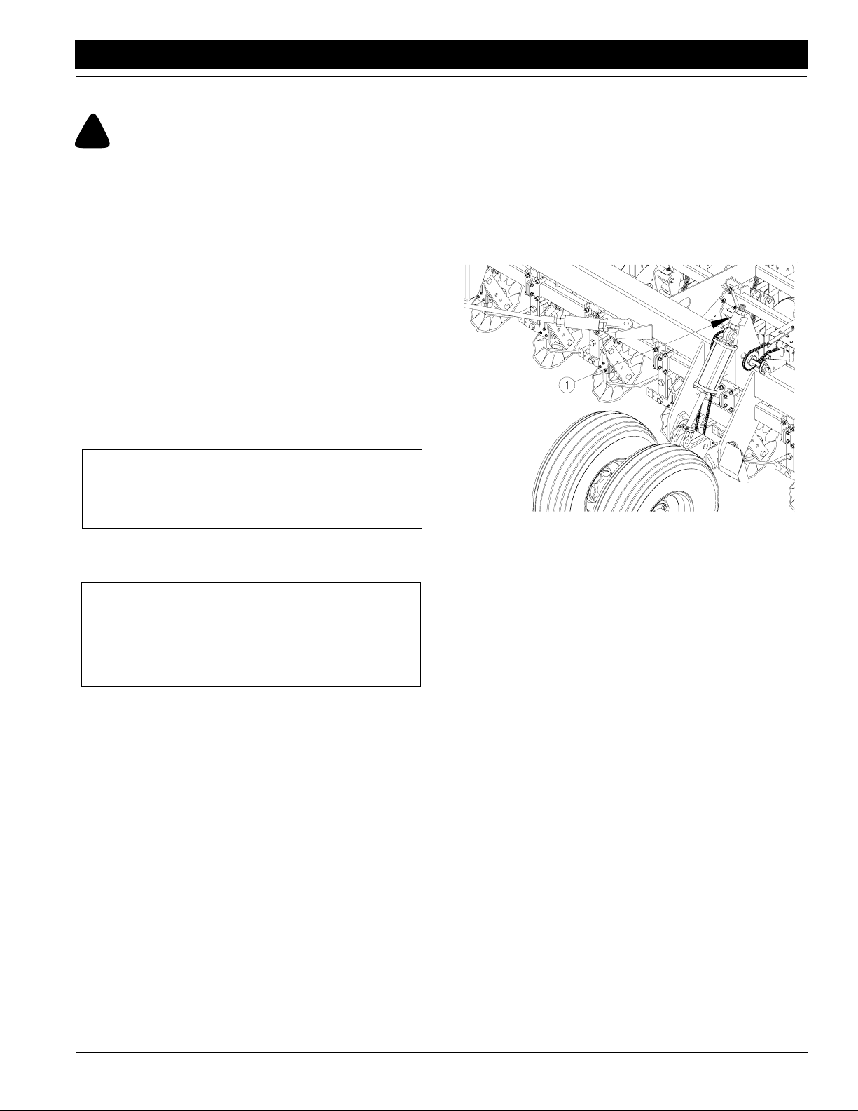
1. Locate the threaded eye bolt at the base end of the
gauge-wheel cylinders (1). The eye bolt is locked in
place bya jam nuts. Observe the amountof thread exposed abovethe upper nut andbelow the lower nut. If
the exposed threads are roughly equal, no initial adjustment is needed. Go to step 3.
2. If the exposed threads above and below the nuts are
not equal, loosen and adjust the jam nuts until the exposed threads are within 3/8 inch of each other.Repeat for other end of drill.
12779
Figure 1-4
Wing Gauge Wheel Eye-Bolt Adjustment
3. Move the drill to a level area. With the drill unfolded,
check that the tool-bar cylinders are completely extended. Raise the drill to its highest position with the
field-lift cylinders. With the tractor idling, rephase the
cylinders by holding the hydraulic lever on for an additional 30 seconds. Immediately lower the boxes until
the coulters and openers are just ready to touch the
ground.
4. Move the gauge-wheel eye bolts (1) in or out until the
framesare level.Whentheframesare level,theopeners on the outside end of the drill will be the same
height as the center openers.
NOTE: Eye-bolt adjustments are easier if the drill is first
lowered to the ground to remove some of the force on the
cylinders.
5. Repeat the steps above until the drill is level end-toend when drilling in actual seeding conditions.
12/27/05
2N-2410 and 2N-3010 Folding No-Till Drill 196-126M
13
Page 16
Section 1 Drill Preparation and Setup
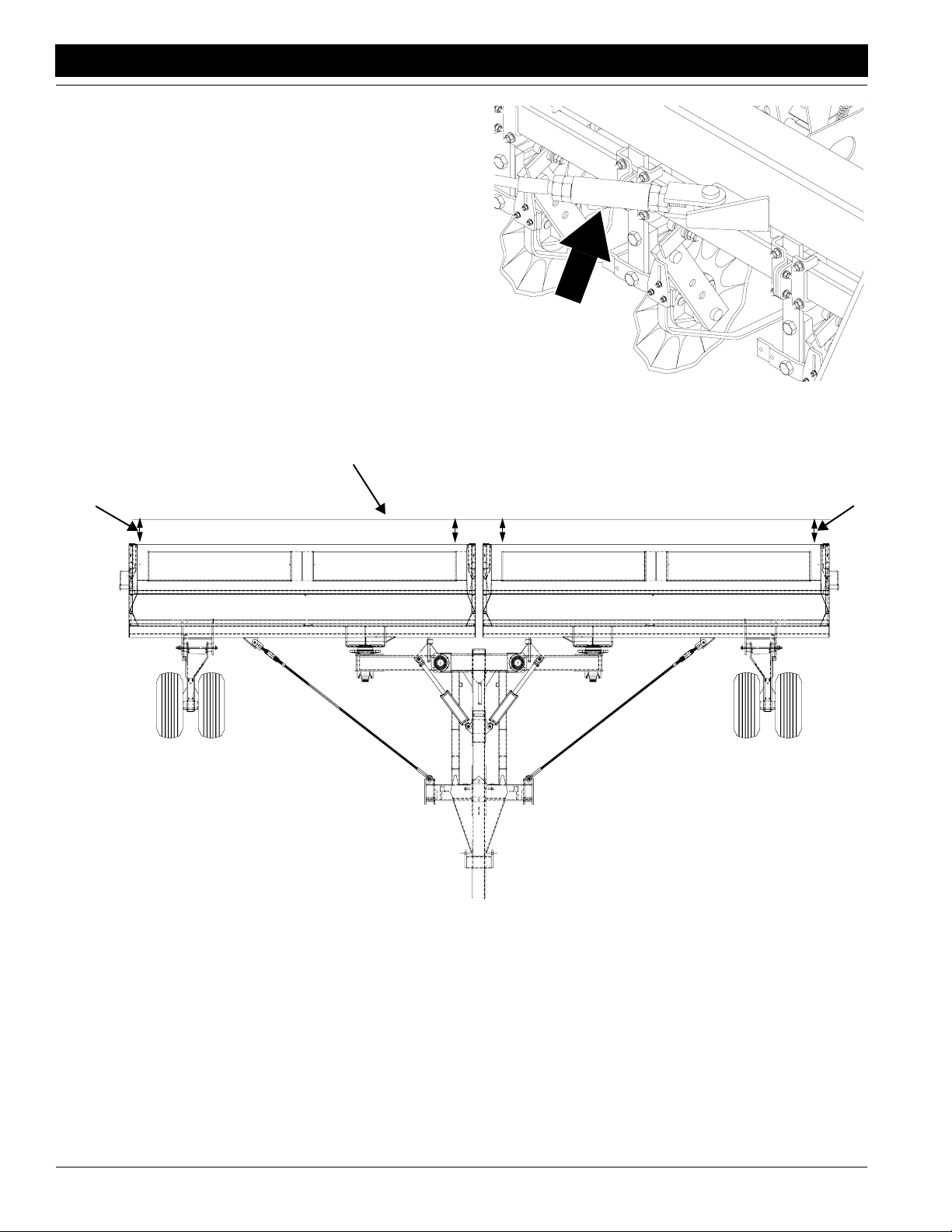
Aligning Boxes
For proper alignment, the outside ends of the drill boxes
mustbe 1 to 1 1/2 inches ahead of the inside ends. Follow
these steps to check box alignment and adjust as
necessary.
1. With the drill unfolded and lowered,pull forward a few
feet with the openers in the ground.
2. Extendastringlinetothe outer endsofthewingboxes
asshowninFigure 1-5. Measure fromthestringlineto
each box as shown. For each box, measurement A
shouldbe1to11/2inchesgreaterthan measurement
B.
3. If adjustment is needed, write down howmanyinches
the box should be moved to be within the 1- to 1 1/2inch tolerance mentioned above. Also note the direction you need to move the outside end of the box–forward or back.
String Line
Great Plains Mfg., Inc.
12778
Figure 1-6
Box Alignment Adjustment
Measurement A
Measurement B
Figure 1-5
Box Alignment Measurements
4. Makeadjustmentsattheboxend of each pull cable as
shown in Figure 1-6. Loosen the jam nuts on the adjustment trunnion screw. Turn the screw in or out to
move the box end forward or backward as required.
Retighten the jam nuts.
5. Pull ahead slightly and check the box alignment. Readjust the pull cables if necessary.
Measurement A
Measurement B
16306
2N-2410 and 2N-3010 Folding No-Till Drill 196-126M 12/27/05
14
Page 17
Great Plains Mfg., Inc.
Section 2 Operating Instructions
Section 2 Operating Instructions
This section will help you prepare the tractor and drill for
use.Itwill also give you general operating procedures. Experience,machinefamiliarityand the followinginformation
will lead to efficient operation and good working habits. Always operate farm machinery with safety in mind.
Prestart Checklist
1. Carefully read “Important Safety Information,” page
1.
2. Lubricate the drill as indicated under Lubrication,
“Maintenance and Lubrication,” page 41.
3. Check all tires for proper inflation as indicated on Tire
Inflation Chart,“Appendix,”page 50.
4. Check all bolts, pins and fasteners. Torque as specified on TorqueValues Chart,“Appendix,” page 50.
5. Check the drill for worn or damaged parts. Repair or
replace them before going to the field.
6. Checkhydraulichoses, fittingsandcylindersforleaks.
Repair or replace them before going to the field.
7. Check disk scrapers for proper adjustment. Refer to
Disk Scraper Adjustment,“Adjustments,”page 34.
8. Check that the drive-clutch linkage is operating properly. The clutch jaws should be fully engaged with the drill
in seeding position. When the drill is fully raised the
clutch jaws should be completely separated.
9. Rotate both gauge wheels to see that seed cups and
drive are working and free from foreign material.
Tractor Requirements
Recommended Minimum Tractor Size
24-foot drill - 165 horsepower
30-foot drill - 200 horsepower
NOTE: When determining tractor size, soil type, terrain
and tillage practices must be considered.
Hitching Tractor to Drill
1. Use the drill jack to raise or lower the tongue as needed. Hitch the drill to the tractor using a hitch pin of adequate strength (at least one inch in diameter).
2. Installaretainingcliponthehitchpintopreventit from
workingup.Securelyattachdrillsafety chain to tractor
drawbar.
!
WARNING!
Escaping fluid under pressure can have sufficient pressure to
penetrate the skin causing serious injury. Avoid the hazard by
relieving pressure before disconnecting hydraulic lines. Use a
piece of paper or cardboard, NOT BODY PARTS, to check for
leaks. Wear protective gloves and safety glasses or goggles
whenworkingwithhydraulic systems. If anaccidentoccurs,see
a doctor immediately. Any fluid injected into the skin must be
surgically removed within a few hours or gangrene will result.
3. Connect hydraulic hoses to tractor remotes. One pair
of hoses is for the field-lift cylinders. The other pair is
for raise-to-fold, transport-lock, fold and marker cylinders.
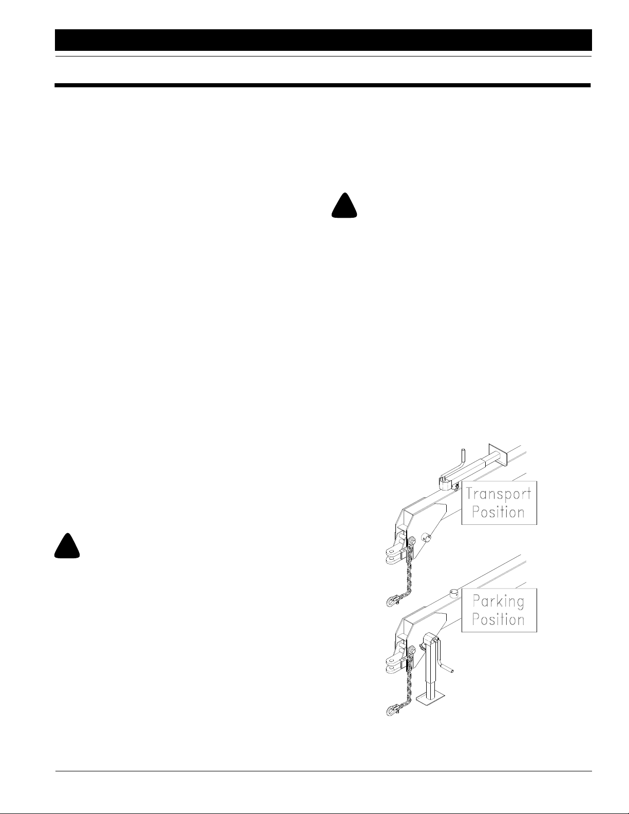
4. Plug the control-console cable to the drill harness.
Plug the drill light cable to the tractor.
5. Crank the jack until tongue weight is resting on the
tractor drawbar. Unpin the tongue jack from the hitching stub.Pin the jack to the stub on top of the tongue
as shown in Figure 2-1.
!
WARNING!
Towing the drill at high speeds or with a vehicle that is not
heavy enough canleadtolossofvehiclecontrol. Loss of vehicle
control can lead to serious road accidents, injury and death.
The reduce the hazard:
• Do not exceed 20 mph.
• Use a towing vehicle heavy enough to controlthe drill.
Minimum Towing Vehicle Weight
16,000 pounds
Hydrualics
Your tractor must have two remote outlets.
Safety Lights
Your tractormustbe wired for the standard 7-pinelectrical
connector.If your tractor is not equipped with this connector, consult your dealer for installation.
12/27/05
12782
Figure 2-1
Jack Positions
2N-2410 and 2N-3010 Folding No-Till Drill 196-126M
15
Page 18

Section 2 Operating Instructions
Great Plains Mfg., Inc.
Operating Control Console
Your drill is equipped with a control console that is mounted in the tractor cab. Refer to Drill Control Console Hook-
Up,“DrillPreparationandSetup,”page 11. Theconsole
is designed to control drill folding and optional markers,
electric clutches and shaft monitors. The console has a
master switch that must be on when operating any of
these systems.
The raise-to-fold,transport locks and foldswitchesare operated independently.Turn only one of these switches on
atonetime.Duringfieldoperations,turn all three switches
off.
To operate markers, turn the marker switch to the left position during field operation. Turn this switch to the center
position (off) when folding or in transport.
Operating Electric Clutch Consoles
To operate electric clutches, turn either the left or right
clutch switch to the off position to shut down the seeding
from the corresponding box. Turn the electric clutch
switches off when folding or in transport.
Tooperateshaftmonitors,turn the shaft monitor switchon
during field operation and off when folding or transporting.
Folding the Drill
!
CAUTION!
To prevent serious injury or death:
• Always use transport locks when drill is folded.
• Fold only if hydraulics are bled free of air and fully charged
with hydraulic oil.
• Stay away from frame sections when they are being raised or
lowered.
• Keep away and keep others away when folding or unfolding
the drill.
Fold the drill on level ground with the tractor in neutral. If
yourdrill has markers,be certain theyare folded and their
control switches are off before folding. If your drill has a
harrow attachment, fold the attachment beforefolding the
drill. Refer to Folding Harrow Attachment, page 16.
1. Raise drill with field-lift cylinders until cylinders are fully extended.
2. Turn on master power switch on control console. Turn
on raise-to-foldswitch.
3. Work tractor hydraulic lever to raise drill into fold position.
4. Turn off raise-to-fold switch. Turn on transport-locks
switch.
5. Worktractorhydrauliclever to extendlockcylinders.If
lockcylinderswillnotextend,drillisnotfullyraised;repeat steps 1 through 3.
NOTE: If your tractor is equipped with hydraulic flow controls,adjust flow-control valveforthiscircuit to the slowest
position.
6. Turn off transport-locks switch. Turn on fold switch.
7. Work tractor hydraulic leverto slowly retract foldcylinders.
IMPORTANT: Never attempt to fold without first operating the raise-to-fold and transport-lock systems. Otherwise, serious equipment damage will occur.
8. Once drill is foldedovertransportcarriers,turn off fold
switch. Turn on raise-to-fold switch.
9. Work tractor hydraulic lever to lower boxes onto carriers.
10. Turn off raise-to-fold switch.
Folding Harrow Attachment
Beforehydraulicallyfolding drill, foldoptional coil-tine harrow as explained below.
1. Fold right-hand harrow assembly up until locking pin
engages into the first slot on harrow bracket.
2. Fold left-hand harrow assembly up until locking pin
engages into the second slot on harrow bracket.
Unfolding the Drill
!
CAUTION!
This drill has negative tongue weight when unfolded and
raised. Be certain the drill is hitched securely to your tractor
drawbar and the hitch safety chain is securely attached to the
tractor before raising or unfolding the drill.
!
CAUTION!
To prevent serious injury or death:
• Always use transport locks when drill is folded.
• Fold only if hydraulics are bled free of air and fully charged
with hydraulic oil.
• Stay away from frame sections when they are being raised or
lowered.
• Keep away and keep others away when folding or unfolding
drill.
Unfold the drill on level ground with the tractor transmission in neutral.
1. On control console, turn on raise-to-fold switch.
2. Work tractor hydraulic leverto raise boxes off transport carriers.
3. Turn off raise-to-fold switch. Turn on fold switch.
4. Work tractor hydraulic leverto slowly unfold drill boxes.
5. When drill is unfolded completely, turn off fold switch.
Turn on transport-lock switch.
6. Work tractor hydraulic leverto retract transport-lock
cylinders.
NOTE:Iftransport-lockcylinderswillnotretract,drillisnot
raised fully.Make sure field-lift cylinders and transport-lift
cylinders are extended fully.
2N-2410 and 2N-3010 Folding No-Till Drill 196-126M 12/27/05
16
Page 19

Great Plains Mfg., Inc.
Section 2 Operating Instructions
7. When transport-lock cylinders are retracted, turn off
transport-lock switch. Turn on raise-to-fold switch.
8. Work tractor hydraulic leverto lower drill.
9. Turn off raise-to-fold switch.
Lifting the Drill in the Field
Your drill is raised for field operations with hydraulic cylinders in a master-slave configuration. Overa period of normalusethecylindersmay get out ofphase.Thiswillcause
onesideofthedrilltorunhigher.To rephase the cylinders:
1. Raise the drill completely with the field-lift cylinders.
Holdthehydraulicleveronforseveral secondsuntilall
cylinders are fully extended. This should be done every time the implement is raised out of the ground.
2. When all field-lift cylinders are fully extended, momentarily reversethe hydraulic leverto retract the system
1/2 inch. This will help maintain levelness.
NOTE: Air in the field-lift system will cause jerky and unevencylinder movement. Follow procedures under Bleed-
ing the Hydraulic Systems,“Drill Preparation and
Setup,” page 11, to properly bled air from the system.
Field Operations
For normal seeding operations:
1. Hitch drill to a tractor with sufficient weight and horsepower. Refer to TractorRequirements, page 15, and
Hitching Tractorto Drill, page 15.
2. Perform all checks listed on Prestart Checklist, page
15.
3. Lower the drill into seeding position.
4. Observe the drill from the side. Check that the tongue
is running levelwith the ground. If not, refer to Hitch
Height Adjustment,“Drill Preparation and Setup,”
page 10.
5. Set the seeding rate for both boxes. Refer to Setting
the Seeding Rate,“Adjustments,”page 22. Make
sure the seeding rate is the same across the drill.
6. Load boxeswith clean seed.
7. Record the acremeter readout. The acremeter is
mounted on the outside end of the left gauge-wheel
shaft. Subtract this initial readout from later readings
to calculate area drilled.
8. Pull forward, lower drill, and begin seeding.
9. Always lift the drill out of the ground when turning at
row ends and for other short turns. Seeding will stop
automatically as the drill is raised in the field.
NOTE:This drill is offered in three different row spacings.
Some of the drill boxes do not have the same number of
seed cups between each internal boxdivider.Thesection
with the largest number of cups will empty sooner.
Opener Operation
Neverbackup with openers in ground. If you do,check all
openers to be sure none are clogged or damaged.
For information on setting seed depth and opener adjustments,seeNo-TillSeeding,“Adjustments,”page19,and
LevelingAdjustments,“Adjustments,” page 34. Formore
information on troubleshooting opener problems, see
“Troubleshooting,” page 37.
Marker Operation
Optionalmarkerattachmentsare sold assingle(left-hand)
or dual units. The markers are operated on the same electro-hydrauliccircuitastheraise-to-fold,transport-lockand
folding functions.
Before operating the markers, make sure they are properlybledasdescribedunderBleedMarkerHydraulics,“Drill
Preparation and Setup,” page 13.
To operate the markers,turn the control-console switch to
the left marker position after the drill is unfolded. Activate
the hydrauliclever to fold or unfold the marker.
Thedualmarkersareequippedwith a sequencing valveto
ease marker operation. Startingwith both markers folded,
the sequence is:
1. Activate lever. Right unfolds; left marker stays folded.
2. Reverse lever.Right folds up; left stays folded.
3. Activate lever. Left unfolds; right stays folded.
4. Reverse lever.Left folds up; right stays folded.
5. Sequence repeats.
NOTE: Because of the sequencing valve, do not turn
marker switch between the left and right positions on the
control console. The left-marker position controls both
markers.Ifyouwishtooperatethe markersindependently,
contact your Great Plains dealer for additional parts to
modify the marker hydraulics.
Markers are equipped with needle valves to set folding
speed. Refer to Folding Speed,“Adjustments,” page 35,
and adjust folding speed to a safe rate. Folding or unfolding markers at high speed can damage markers.
Whenmarkeroperationiscomplete,return markers to the
folded position and turn the marker switch to the center
(off) position.
12/27/05
2N-2410 and 2N-3010 Folding No-Till Drill 196-126M
17
Page 20

Section 2 Operating Instructions
Great Plains Mfg., Inc.
Shaft Monitor Operation
To operate the optional shaft monitors,turn the shaft-monitor switch on the control console to the on position. If either seed-cup shaft stops for 20 seconds, an alarm will
sound. A light on the control console will designate the
failed shaft.
The 20-second delay is to prevent nuisance alarms when
turning at the end of the field. If the alarm sounds, remember you have traveled for 20 seconds without seeding.
Electric Clutch Operation
Electrical clutches on the upperjackshaftturn seeding off
and on as the drill is raised and lowered in the field. The
electricclutchesallowyouto turnseedingoffwhilethedrill
is lowered. A clutch for each drive shaft allows you to control each drill box independently. The clutches are controlled through the in-cab control console.
For regular field operation, turn the electric-clutch switches on the control console to the on position. This will activatethemagnetoneachclutchandallow the clutch shafts
to rotate.
To shut off seeding in one or both boxes while the drill is
lowered, turn one or both switches to the off position.
Transporting
!
CAUTION!
This implement should never be towed faster than 20 mph.
Before transporting, check and practice the following
items.
Fold Drill. Transport the drill in folded position with transport-lock cylinders extended. Refer to Folding the Drill,
page 16.
Loaded Boxes. This drill can be transported with boxes
loaded with grain, but only with extreme caution. The additional weight reduces maneuverability and increases
stopping distance.
Stopping Distance. Keep the weight of this drill in mind.
Allow sufficient stopping distance at all times. Reduce
speed prior to making any turns or other maneuvers. Increase stopping distance if transporting with loaded boxes.
Bystanders. Check that no one is in the way before moving. Do not allow anyone to ride on the drill.
Tractor Requirements. Check that the towing vehicle is
large enough to control the drill on the road. Refer to Trac-
tor Requirements, page 15.
Clearance. Know drill dimensions in transport position
and follow a route that provides adequate clearance from
all obstructions. Refer to Specifications and Capacities,
page 49.
Tires. Check that all tires areproperly inflated as listedon
Tire Inflation Chart,“Appendix,”page 50.
Road Rules. Comply with all federal, state and local laws
when transporting on public roads.
Warning Lights. Always use warning lights when trans-
porting the drill.
Watch Traffic.Be prepared for sudden maneuvers from
following vehicles.
Markers. Always transport optional markers folded flat.
Make sure the second marker section rests securely on
the transport carrier.
HarrowAttachment. Foldtheoptionalharrow attachment
beforehydraulically folding drill fortransport. RefertoFold-
ing the Harrow, page 16.
Parking
Performthefollowingsteps when parking the drill. Referto
Storage,“Maintenance and Lubrication,” page 40, for in-
formation on long-term storage preparation.
1. Raise, lock and fold the drill in the transport position.
Refer to Folding the Drill, page 16.
2. Park the drill on a level, solid area.
3. Securely block the tires to preventrolling.
4. Remove the jack from its storage stub. Pin the jack in
parking position. See Figure 2-1, page 15. If the
ground is soft, place a board or plate under the jack.
5. Extend the jack until tongue weight is off the drawbar.
6. Unplug the hydraulic lines from the tractor. Do not allow hose ends to rest on the ground.
7. Unplug the control-console cable from the tractor. Unplug the drill light cable from the tractor.
8. Remove hitch pin and safety chain from tractor drawbar.
2N-2410 and 2N-3010 Folding No-Till Drill 196-126M 12/27/05
18
Page 21

Great Plains Mfg., Inc.
Section 3 Adjustments
Section 3 Adjustments
No-Till Seeding
To get full performance from your no-till drill, you need a
good understanding of coulter, opener and press wheel
operation.
Coulters. A no-till coulter is mounted independently and
directly ahead of each opener. The coulters cut through
heavy trash and make a groove in the soil. The coulters
are mounted directly on the box frame. Consequently,the
cutting depth of all coulters changes as the drill is raised
andlowered.Thecutting depth ofthecoultersiscontrolled
byan adjustable hydraulicdepth stop.Coulters that run directly in tire tracks can be lowered individually. Refer to
Coulter Adjustments, this page, for information on how to
make these adjustments.
Openers.Eachopeneris mounted onthedrillwithparallel
arms. This parallel-action mounting allows the opener to
move up and down while staying in-line with a coulter.
Opener double disks widen the coulter groove, making a
seed bed. A seed tube mounted between the disks delivers seed to the trench.The down force needed to cut and
widenthecoultergrooveis supplied by twospringsnested
in the parallel linkage. Adjusting these springs changes
opener down-force. Refer to Opener Down-Pressure Ad-
justment, page 22, forinformation on how to make this adjustment.
Press Wheels. Attached to the rear of each opener is one
of severalpress-wheeloptions. The press wheels provide
two important functions.
First, the press wheels close the furrow, gently pressing
the soil over the seed. To provideconsistent seed firming,
the press wheels are free to move downward from their
normal operating position. This system maintains pressing action even if the opener arm is lifted when the disks
encounter obstructions.
Second, the press wheels provide opener depth control.
The higher the press wheels run relative to the double
disks, the deeper seed will be placed. Tomaintain a consistentdepth,upwardpress-wheelmovementisrestricted
by an independently adjustable stop on each opener. Refer to PressWheelAdjustment,page 22,forinformationon
how to make this adjustment.
Coulter Adjustments
The drill is assembled so thatwhen the coulters are at two
inches deep, the seeding depth is about one inch. This is
a good baseline setting for most seeding operations. As
field conditions warrant, you can change settings on the
entire drill or individual coulters.
Hydraulic Depth Control
The master field-lift cylinder on the left transport wheel is
equipped with a hydraulic valvethat regulates coulter
depth.Figure3-1showsthevalve and knob used to adjust
coulter depth.
Raise Coulters
Lower Coulters
16271
Figure 3-1
Left Transport-Wheel Cylinder with Depth-Control Stop
Turn the knob clockwise to lower the coulters. Each clockwise rotation will lower the coulters about 3/32 inches.
Make depth adjustments with the implement slightly
raised.Afteradjusting the valve,raiseandlowertheimplement several times and recheck coulter depth.
The depth stop regulates depth on all coulters. If the ends
of either box run higher or lower than the center,the fieldlift system may be out of phase or have air in it, or the
framesections maynotbe level.RefertoLiftingtheDrill in
theField,“Operating Instructions,” page 17, Bleed Field-
LiftHydraulics,“Drill Preparation andSetup,” page11,or
LevelingAdjustment, page 34.
12/27/05
2N-2410 and 2N-3010 Folding No-Till Drill 196-126M
19
Page 22

Section 3 Adjustments
Electric Clutch Switch Adjustment
To adjust the height at which seed metering is turned off,
follow these steps.
Refer to Figure 3-2
1. Locate the height switch at left-hand gauge wheel.
2. Lower the implement until it is at a height where seeding should start (usually just above the ground). Securely support frame at this height with jack stands or
blocks.
3. Turn off the tractor and remove the key.
Great Plains Mfg., Inc.
Refer to Figure 3-3
4. Loosen the cam clamp (1) on the gauge wheel rockshaft and turn until the switch roller (2) is just starting
to make contact with the ramp surface.
Refer to Figure 3-4
5. Raise the implement fully and check that the switchis
compressed as shown.
19711
Figure 3-2
15160
Figure 3-3
14550
Figure 3-4
2N-2410 and 2N-3010 Folding No-Till Drill 196-126M 12/27/05
20
Page 23

Great Plains Mfg., Inc.
Section 3 Adjustments
Weights
Ifmoreweightis required forcoulterstopenetratethesoil,
weight bracket kits are available from your Great Plains
dealer. Refer to Weight Brackets,“Options,” page 45 for
part numbers and ordering information.
Referto the charts below forthe results of adding weights
toyourdrill.Always addanequalamountofweightto each
box frame. Never add more than 500 pounds to each box
frame.
Weight Chart, 24-Foot Drill
71/2-In.
Rows
8-In.
Rows
10-In.
Rows
Empty Drill, Pounds 17,400 17,100 16,000
Pounds Per Coulter,
305 320 390
No Weights
Pounds Per Coulter,
Brackets and 1000
330 340 420
Pounds Added
Weight Chart, 30-Foot Drill
71/2-In.
Rows
8-In.
Rows
10-In.
Rows
Coulter Down-Pressure Chart
Spring Length Coulter Force
10 1/4 in. 300 lb.
10 in. 400 lb.
9 3/4 in. 525 lb.
NOTE: Any attempt to reset the coulter spring length
shorter than 9 3/4 inches may contribute to premature failure of parts and warrantywillbe voided. If additional force
is necessary, add weights to the implement.
Individual Coulters
Whencoulters followintire tracksanddo not give satisfactory depth, individual coulters can be lowered by loosening the mounting clamps and adjusting the coulter to the
desired setting.
To retighten clamps, snug the hex-head clamp bolts (1)
just until the u-bolts are tight on each side of the spring
bar. Tighten nuts on u-bolts (2), then finish tightening the
hex-head clamp bolts.
Empty Drill, Pounds 20,100 19,600 18,400
Pounds Per Coulter,
285 300 335
No Weights
Pounds Per Coulter,
Brackets and 1000
305 325 385
Pounds Added
NOTE:Optional markers, harrows and small-seed attachments add about 25 pounds per coulter. Completely loading the grainor small-seed boxesaddsabout 100 pounds
per coulter.
Coulter Springs
The coulter spring length is preset at10 inches, giving the
coulter an initial operating force of 400 pounds. This setting is adequate for many difficult no-till conditions. For
lighter no-till conditions where rocks or other obstructions
are a problem, you can lengthen thesprings to protectthe
coultersfromimpact.Inheavierconditions, shorteningthe
spring will increase coulter force.Referto the chart below
for adjusting the coulter springs.
10300
Figure 3-5
Individual Coulter Height Adjustment
IMPORTANT: Neverlower any coulter more than 1 1/2
inches. Tire damage could result as the drill is folded.
Also note that when the drill is in the raised position,
ground clearance on lowered coulters is reduced.
NOTE:There may be as much as a 1/8-inch gap between
the clamp plates even when the coulter is mounted securely.
12/27/05
2N-2410 and 2N-3010 Folding No-Till Drill 196-126M
21
Page 24

Section 3 Adjustments
Great Plains Mfg., Inc.
Opener Down-Pressure Adjustment
You can adjust spring down pressureindividually for each
opener. This is useful for penetrating hard soil and planting in tire tracks.
To adjust down pressure, use the adjustment tool stored
under the walkboard. Position the tool in the holes on the
spring mounting plates and pull down on the adjuster as
shown Figure 3-6.
12105
Figure 3-6
Opener-Spring Adjustment
Minimum and maximum settings are indicated by the position of spring adjuster as shown in Figure 3-7.
12104
MinimumForce
Figure 3-7
Spring Settings
Maximum Force
Press Wheel Adjustment
Changing the height of the press wheel automatically
changes seeding depth. To adjust, lift up on the T-handle
and slide it forward or back as shown in Figure 3-8.
• For shallower seeding, slide the handle toward the im-
plement.
• For deeper seeding, slide the handle away from the im-
plement.
Setting the Seeding Rate
Calibrating the seeding rate requires four steps: shifting
the speed-change gearbox, adjusting the seed-rate handle,settingthe seed-cup doors, and checking the seeding
rate.
Check the seed-rate charts starting on page 24 or in the
drill boxes. These charts list the proper settings for the
speed-change gearbox and seed-rate handle for various
seeds and seeding rates.
The seed-rate charts are based on cleaned, untreated
seed of averagesizeandtest weight. The rates are based
on 11L x 15 8-ply rib implement tires and 265/70B16 skid
steer tires. Many factors will affect seeding rates including
foreign material, seed treatment, seed size, field conditions, tire pressure and test weight. Minor adjustments
likelywillbeneeded.Setandcheckthe seeding rate using
the procedures below, then re-adjust the rate as necessary.
Beforesetting the seeding rate, rotate both gauge wheels
to see that the seed cups and drive are working properly
and free from foreign material.
NOTE: Each drill box has its own metering mechanism.
After adjusting and checking the rate on one box, set the
same rate on the other box.
1. Shift Speed-Change Gearbox
The speed-change gearbox, Figure 3-9, is designed
to give you a variety of speeds for different seeds and
seeding rates. You can shift between four different
drive types.
Refer to the seed-rate charts for the correct drive
type–1, 2, 3 or 4. Move the selector handle on the
gearbox until the correct number appears in the handle window as shown in Figure 3-9. Rotate the tires a
few turns to confirm the gearbox has engaged.
Figure 3-9
12100
Figure 3-8
Press Wheel Adjustment
2N-2410 and 2N-3010 Folding No-Till Drill 196-126M 12/27/05
22
Speed-Change Gearbox
12916
Page 25

Great Plains Mfg., Inc.
Section 3 Adjustments
Gearbox Ratios:
Drive Type 2 is 2.06 Times Faster Than 1
Drive Type 3 is 3.08 Times Faster Than 1
Drive Type 4 is 5.03 Times Faster Than 1
2. Adjust Seed-Rate Handle
Positionthehandle(Figure3-10)tothesettingindicated on the seed-rate chart. To adjust, loosen the wing
nut under the handle and slide until indicator lines up
with desired setting. Retighten nut.
12927
Figure 3-10
Seed-Rate Handle
3. Set Seed-Cup Doors
Forwheat and other small seeds, move the seed-cupdoor handles to the highest position. For soybeans
and other large seeds, lower the handles to the secondposition. If excessiveseedcrackingoccurs,lower
the handles to the third position. For seed-cup clean
out, movethe handles to the fourth, wide-open position. Make sure all handles are in the same position
before drilling.
4. Check Seeding Rate
a. Place severalpoundsofseed overthe three seed
cups on the outside end of the drill box.
b. Disconnecttheseedtubes fromthethreeopeners
fed by the covered cups.
c. Raise the drill off the ground.
d. Record the empty weight of a container large
enough to hold the seed metered for one acre.
e. Turn gauge wheels until seed drops to the ground
from each cup.
f. Place a container under the three seed tubes to
gather the seed as it is metered.
g. Rotate the gauge wheel until one acre has been
tallied on the acremeter. This will be
about 225 rotations on a 24-foot drill and about
181 rotations on a 30-foot drill. Check that the
seed cups have plenty of seed coming into them.
h. Weigh the metered seed. Subtract the initial
weight of the container. Divide by three. Multiply
by the number of openers on your drill for the
pounds-per-acre seeding rate. If this figure is dif-
ferent than desired, re-adjust the seed-rate han-
dle and recheck the rate.
5. When satisfiedwiththeseedingrate,repeatsteps1
through3forthe other drill box,settingittothe same
rate.
Small Seeds Attachment
To set the seeding rate, refertothe small-seeds-rate chart
onpage32.Movetheseed-ratehandleontheattachment
to the setting indicated on the chart.
To calibrate the attachment to your material, followthe
steps listed under Check Seeding Rate, this page.
13867
12/27/05
Figure 3-11
Seed-Cup Door Handle
2N-2410 and 2N-3010 Folding No-Till Drill 196-126M
23
Page 26

Great Plains Mfg., Inc.
Section 3 Adjustments
Seed Rate Charts (Pounds per acre)
Setting number 0 5 10 15 20 25 30 35 40 45 50 55 60 65 70 75 80 85 90 95 100
Alfalfa
Drive Type 1
(Based on
60#/bu)
Row Space
1.8 4.6 7.0 10.0 12.8 16.0 19.1 22.7 26.3 30.7 34.3 37.5 41.5 45.3 49.3 52.9 57.5 61.8 66.3 68.3 70.2
7.5"
1.7 4.3 6.5 9.4 12.1 15.0 17.9 21.3 24.7 28.8 32.2 35.2 39.0 42.6 46.3 49.6 54.0 58.0 62.3 64.1 65.9
8"
1.4 3.5 5.2 7.5 9.7 12.0 14.4 17.1 19.8 23.1 25.8 28.2 31.2 34.1 37.1 39.8 43.2 46.5 49.9 51.4 52.8
10"
Barley
Drive Type 1
(Based on
51#/bu)
Barley
Drive Type 2
(Based on
51#/bu)
Buckwheat
Drive Type 2
(Based on
48#/bu)
Buckwheat
Drive Type 3
(Based on
48#/bu)
Buffalo Grass
Drive Type 1
(Based on
23#/bu)
Bermuda Grass
Drive Type 1
(Based on
60#/bu)
BermudaGrass
Drive Type 2
(Based on
60#/bu)
1.6 3.8 6.3 8.9 12.0 15.1 18.6 21.8 25.2 28.9 32.5 36.2 40.0 44.2 47.8 51.6 54.8 57.8 60.7 61.2 61.7
7.5"
1.5 3.5 6.0 8.4 11.3 14.2 17.4 20.5 23.7 27.1 30.6 34.0 37.6 41.5 44.8 48.5 51.5 54.2 57.0 57.4 57.9
8"
1.2 2.8 4.8 6.7 9.0 11.4 14.0 16.4 19.0 21.7 24.5 27.2 30.1 33.2 35.9 38.8 41.2 43.5 45.6 46.0 46.4
10"
Row Space
7.5" 2.9 7.2 13.3 18.0 24.9 30.9 37.7 44.9 51.7 59.4 66.4 72.8 80.2 87.1 95.0 102.6 111.1 119.1 126.8 128.8 130.8
8" 2.7 6.8 12.4 16.9 23.4 29.0 35.4 42.2 48.5 55.8 62.3 68.3 75.2 81.7 89.2 96.3 104.3 111.8 119.0 120.9 122.8
10" 2.2 5.4 10.0 13.6 18.7 23.2 28.4 33.8 38.9 44.7 49.9 54.7 60.3 65.5 71.4 77.2 83.5 89.6 95.3 96.8 98.4
Row Space
0.0 4.5 11.7 17.2 24.3 30.6 36.5 43.8 51.2 58.3 65.7 72.4 79.5 86.9 93.7 101.9 107.8 114.4 121.2 122.0 122.7
7.5"
0.0 4.2 10.9 16.2 22.9 28.7 34.3 41.1 48.1 54.7 61.7 68.0 74.6 81.6 87.9 95.6 101.2 107.4 113.8 114.5 115.2
8"
0.0 3.4 8.8 13.0 18.3 23.0 27.5 32.9 38.5 43.8 49.4 54.5 59.8 65.4 70.5 76.6 81.1 86.1 91.2 91.8 92.3
10"
Row Space
0.0 9.4 17.6 24.6 35.0 43.7 54.4 65.2 77.3 89.3 103.0 113.5 125.8 138.3 150.2 163.5 175.0 187.4 211.3 202.3 204.5
7.5"
0.0 8.8 16.5 23.1 32.9 41.0 51.0 61.2 72.5 83.9 96.7 106.5 118.1 129.9 141.0 153.5 164.3 175.9 198.3 189.9 191.9
8"
0.0 7.1 13.2 18.5 26.3 32.9 40.9 49.0 58.1 67.2 77.4 85.3 94.6 104.0 112.9 122.9 131.6 140.9 158.9 152.2 153.8
10"
Row Space
0.0 0.4 1.8 3.1 4.5 5.9 7.3 8.8 10.3 11.7 13.0 14.0 15.1 16.1 17.3 18.6 20.0 21.5 23.0 21.7 20.4
7.5"
0.0 0.4 1.7 2.9 4.2 5.5 6.9 8.2 9.6 11.0 12.2 13.2 14.2 15.1 16.2 17.5 18.8 20.1 21.6 20.4 19.1
8"
0.0 0.3 1.4 2.3 3.4 4.4 5.5 6.6 7.7 8.8 9.8 10.5 11.4 12.1 13.0 14.0 15.1 16.1 17.3 16.3 15.3
10"
Row Space
0.0 2.1 3.7 5.6 7.9 9.7 11.5 14.0 16.3 18.4 20.5 22.5 24.4 26.5 28.7 30.7 32.9 34.9 37.1 38.7 40.5
7.5"
0.0 2.0 3.4 5.3 7.4 9.1 10.8 13.2 15.3 17.3 19.2 21.1 22.9 24.9 26.9 28.9 30.9 32.8 34.8 36.3 38.0
8"
0.0 1.6 2.8 4.2 6.0 7.3 8.6 10.5 12.2 13.8 15.4 16.9 18.4 20.0 21.6 23.1 24.7 26.3 27.9 29.1 30.5
10"
Row Space
0.0 4.3 7.5 11.6 16.2 20.0 23.6 28.8 33.5 37.8 42.1 46.2 50.2 54.6 58.9 63.2 67.6 71.8 76.2 79.5 83.3
7.5"
0.0 4.1 7.1 10.9 15.3 18.7 22.2 27.0 31.4 35.5 39.5 43.4 47.1 51.2 55.3 59.3 63.5 67.4 71.5 74.6 78.2
8"
0.0 3.3 5.7 8.7 12.3 15.0 17.8 21.7 25.2 28.4 31.6 34.7 37.8 41.0 44.3 47.5 50.8 54.0 57.3 59.8 62.7
10"
Row Space
BermudaGrass
Drive Type 3
(Based on
60#/bu)
BermudaGrass
Drive Type 4
(Based on
60#/bu)
Fescue K-31
Drive Type 2
(Based on
21#/bu)
Fescue K-31
Drive Type 3
(Based on
21#/bu)
Fescue K-31
Drive Type 4
(Based on
21#/bu)
0.0 5.1 11.5 16.9 24.1 29.9 36.6 42.5 48.8 55.3 61.2 67.6 73.6 79.9 86.0 92.9 97.5 103.6 109.7 114.0 119.1
7.5"
0.0 4.8 10.8 15.9 22.7 28.1 34.4 39.9 45.8 51.9 57.5 63.5 69.1 75.0 80.7 87.2 91.6 97.2 103.0 107.0 111.8
8"
0.0 3.8 8.7 12.7 18.2 22.5 27.5 32.0 36.7 41.6 46.0 50.8 55.4 60.1 64.6 69.9 73.4 77.9 82.5 85.7 89.5
10"
Row Space
7.5" 0.0 8.3 18.8 27.6 39.4 48.8 59.7 69.3 79.5 90.1 99.8 110.2 120.1 130.3 140.1 151.5 159.0 168.9 178.9 185.8 194.1
8" 0.0 7.8 17.6 25.9 37.0 45.8 56.0 65.0 74.6 84.6 93.7 103.5 112.7 122.3 131.6 142.2 149.3 158.5 168.0 174.4 182.2
10" 0.0 6.2 14.1 20.7 29.7 36.7 44.9 52.1 59.8 67.8 75.1 82.9 90.3 98.0 105.4 114.0 119.6 127.0 134.6 139.7 146.0
Row Space
2.3 4.2 6.3 8.9 11.3 13.8 17.1 19.2 22.1 24.8 28.4 30.3 33.0 35.9 38.6 41.3 43.9 46.0 47.8 48.9 49.2
7.5"
2.1 3.9 5.9 8.3 10.6 13.0 16.0 18.0 20.7 23.3 26.6 28.4 31.0 33.7 36.3 38.8 41.3 43.2 44.9 45.9 46.2
8"
1.7 3.1 4.7 6.7 8.5 10.4 12.8 14.4 16.6 18.6 21.3 22.8 24.8 27.0 29.1 31.1 33.0 34.6 35.9 36.8 37.0
10"
Row Space
2.4 5.8 9.7 13.3 17.0 21.5 24.8 29.7 33.8 38.1 41.5 46.1 50.2 54.1 57.9 62.0 65.7 69.1 72.2 72.9 74.9
7.5"
2.3 5.4 9.1 12.5 15.9 20.2 23.3 27.9 31.7 35.8 39.0 43.3 47.1 50.8 54.4 58.2 61.6 64.8 67.8 68.4 70.3
8"
1.8 4.4 7.3 10.0 12.8 16.2 18.6 22.3 25.4 28.7 31.2 34.7 37.8 40.7 43.6 46.6 49.4 51.9 54.3 54.8 56.3
10"
Row Space
3.9 9.4 15.8 21.7 27.7 35.0 40.4 48.4 55.1 62.2 67.7 75.2 81.9 88.2 94.5 101.0 107.1 112.6 117.7 118.9 122.1
7.5"
3.7 8.9 14.8 20.3 26.0 32.9 37.9 45.5 51.7 58.4 63.5 70.6 76.9 82.8 88.7 94.9 100.5 105.7 110.5 111.6 114.7
8"
3.0 7.1 11.9 16.3 20.8 26.3 30.4 36.4 41.4 46.8 50.9 56.5 61.6 66.3 71.1 76.0 80.5 84.7 88.6 89.4 91.9
10"
Row Space
2N-2410 and 2N-3010 Folding No-Till Drill 196-126M 12/27/05
24
Page 27

Great Plains Mfg., Inc.
Section 3 Adjustments
Seed Rate Chart (Con’t.) (Pounds per acre)
Setting number 0 5 10 15 20 25 30 35 40 45 50 55 60 65 70 75 80 85 90 95 100
Flax/Sudan
Drive Type 1
(Based on
55#/bu)
7.5" 0.0 3.1 6.9 9.8 13.5 16.8 20.2 23.6 27.4 30.9 35.0 38.2 41.7 45.5 49.4 54.1 58.3 63.3 68.5 69.6 71.0
8" 0.0 2.9 6.4 9.2 12.6 15.8 19.0 22.2 25.7 29.0 32.8 35.9 39.2 42.7 46.4 50.8 54.8 59.5 64.3 65.3 66.6
10" 0.0 2.4 5.2 7.4 10.1 12.7 15.2 17.8 20.6 23.3 26.3 28.7 31.4 34.2 37.2 40.7 43.9 47.6 51.5 52.4 53.4
Row Space
K.Bluegrass
Drive Type 3
(Based on
23#/bu)
K.Bluegrass
Drive Type 4
(Based on
23#/bu)
Millet
Drive Type 1
(Based on
60#/bu)
Milo
Drive Type 1
(Based on
60#/bu)
Oats
Drive Type 2
(Based on
37#/bu)
Oats
Drive Type 3
(Based on
37#/bu)
Orchard Grass
Drive Type 1
(Based on
18#/bu)
0.0 4.6 7.5 9.9 13.5 15.9 19.1 22.2 25.4 28.7 32.1 35.0 38.1 41.3 44.2 47.4 50.0 52.6 54.8 56.7 58.4
7.5"
0.0 4.3 7.1 9.3 12.7 15.0 17.9 20.9 23.8 27.0 30.2 32.9 35.8 38.8 41.5 44.5 46.9 49.4 51.4 53.3 54.8
8"
0.0 3.5 5.7 7.4 10.2 12.0 14.3 16.7 19.1 21.6 24.2 26.3 28.7 31.1 33.2 35.7 37.6 39.6 41.2 42.7 43.9
10"
Row Space
0.0 7.5 12.3 16.1 22.0 26.0 31.1 36.2 41.3 46.8 52.4 57.1 62.2 67.3 72.0 77.3 81.5 85.8 89.3 92.5 95.2
7.5"
0.0 7.0 11.5 15.2 20.7 24.4 29.2 34.0 38.8 44.0 49.2 53.6 58.4 63.2 67.6 72.6 76.5 80.6 83.8 86.8 89.4
8"
0.0 5.6 9.3 12.1 16.6 19.5 23.4 27.2 31.1 35.2 39.4 42.9 46.8 50.6 54.2 58.2 61.3 64.5 67.1 69.6 71.6
10"
Row Space
1.2 3.9 6.9 9.8 13.1 16.3 19.6 22.8 26.3 29.8 33.3 36.8 40.6 43.8 47.7 51.6 55.2 59.2 63.4 64.4 65.3
7.5"
1.1 3.7 6.4 9.2 12.3 15.3 18.4 21.4 24.7 28.0 31.2 34.5 38.1 41.2 44.8 48.5 51.8 55.6 59.5 60.4 61.3
8"
0.9 2.9 5.2 7.4 9.8 12.2 14.7 17.1 19.8 22.4 25.0 27.7 30.5 33.0 35.9 38.8 41.5 44.5 47.7 48.4 49.1
10"
Row Space
0.0 3.9 7.4 10.9 14.8 18.8 23.3 28.0 32.7 37.5 43.1 47.5 52.5 57.6 62.5 67.6 72.4 76.7 81.7 83.9 85.4
7.5"
0.0 3.7 6.9 10.2 13.9 17.6 21.8 26.3 30.7 35.2 40.4 44.5 49.3 54.0 58.7 63.4 68.0 72.0 76.7 78.7 80.1
8"
0.0 2.9 5.5 8.2 11.1 14.1 17.5 21.1 24.6 28.2 32.4 35.7 39.5 43.3 47.0 50.8 54.5 57.7 61.4 63.1 64.2
10"
Row Space
0.0 2.1 6.1 9.7 14.2 17.5 22.2 25.6 29.8 33.8 38.3 42.3 46.8 51.5 56.2 61.3 65.7 70.3 75.5 77.1 77.9
7.5"
0.0 2.0 5.7 9.1 13.3 16.5 20.9 24.0 28.0 31.7 36.0 39.7 44.0 48.4 52.7 57.6 61.6 66.0 70.9 72.4 73.1
8"
0.0 1.6 4.6 7.3 10.7 13.2 16.7 19.2 22.4 25.4 28.8 31.8 35.2 38.7 42.2 46.1 49.4 52.9 56.8 58.0 58.6
10"
Row Space
0.0 4.3 10.1 14.5 20.0 26.3 32.4 39.1 45.9 52.9 60.4 66.6 73.6 80.4 87.4 94.4 101.4 108.4 115.9 117.3 116.9
7.5"
0.0 4.1 9.5 13.6 18.8 24.7 30.4 36.7 43.1 49.6 56.7 62.6 69.1 75.5 82.0 88.6 95.2 101.8 108.8 110.2 109.7
8"
0.0 3.3 7.6 10.9 15.1 19.8 24.3 29.4 34.5 39.8 45.4 50.1 55.4 60.5 65.7 71.0 76.3 81.5 87.2 88.2 87.9
10"
Row Space
0.0 0.7 1.5 2.2 3.0 3.7 4.4 5.3 6.1 7.0 8.0 8.8 9.8 10.8 11.7 12.8 13.5 14.3 14.9 15.3 15.5
7.5"
0.0 0.7 1.4 2.1 2.8 3.5 4.1 5.0 5.7 6.6 7.5 8.3 9.2 10.1 11.0 12.0 12.7 13.4 14.0 14.3 14.6
8"
0.0 0.5 1.1 1.6 2.3 2.8 3.3 4.0 4.6 5.3 6.0 6.7 7.4 8.1 8.8 9.6 10.2 10.7 11.2 11.5 11.7
10"
Row Space
Orchard Grass
Drive Type 2
(Based on
18#/bu)
Orchard Grass
Drive Type 3
(Based on
18#/bu)
Orchard Grass
Drive Type 4
(Based on
18#/bu)
Peas
Drive Type 3
(Based on
61#/bu)
Peas
Drive Type 4
(Based on
61#/bu)
0.0 1.4 3.1 4.5 6.2 7.6 9.0 10.9 12.6 14.5 16.4 18.2 20.1 22.2 24.1 26.3 27.8 29.3 30.6 31.4 31.9
7.5"
0.0 1.4 2.9 4.2 5.8 7.1 8.5 10.3 11.8 13.6 15.4 17.1 18.9 20.9 22.7 24.7 26.1 27.5 28.7 29.5 30.0
8"
0.0 1.1 2.4 3.4 4.7 5.7 6.8 8.2 9.4 10.9 12.3 13.7 15.1 16.7 18.2 19.7 20.9 22.0 23.0 23.6 24.0
10"
Row Space
0.0 2.7 4.5 6.5 9.1 10.9 13.0 15.5 17.6 20.5 23.1 26.1 29.0 31.9 34.8 37.7 39.8 41.8 43.8 45.4 46.9
7.5"
0.0 2.5 4.2 6.1 8.6 10.2 12.2 14.5 16.5 19.3 21.6 24.5 27.2 29.9 32.6 35.4 37.4 39.2 41.2 42.6 44.0
8"
0.0 2.0 3.4 4.9 6.9 8.2 9.8 11.6 13.3 15.4 17.3 19.6 21.8 24.0 26.1 28.4 30.0 31.4 33.0 34.1 35.3
10"
Row Space
0.0 4.3 7.5 10.6 14.9 17.7 21.1 25.2 28.7 33.5 37.6 42.5 47.2 52.0 56.7 61.5 65.0 68.1 71.5 74.0 76.5
7.5"
0.0 4.1 6.9 10.0 14.0 16.6 19.8 23.7 27.0 31.4 35.3 39.9 44.3 48.8 53.2 57.7 61.0 63.9 67.1 69.5 71.8
8"
0.0 3.3 5.5 8.0 11.2 13.3 15.9 18.9 21.6 25.2 28.3 32.0 35.5 39.1 42.6 46.3 48.8 51.2 53.8 55.7 57.5
10"
Row Space
0.0 0.0 15.8 28.5 43.4 57.5 70.2 85.2 99.5 114.9 129.0 141.7 155.7 168.5 182.5 196.9 209.8 222.6 235.4 236.6 237.7
7.5"
0.0 0.0 14.9 26.7 40.7 53.9 65.9 80.0 93.4 107.9 121.1 133.0 146.2 158.2 171.3 184.9 197.0 209.0 221.0 222.1 223.1
8"
0.0 0.0 11.9 21.4 32.6 43.2 52.8 64.1 74.8 86.4 97.0 106.6 117.1 126.7 137.3 148.1 157.8 167.4 177.0 177.9 178.7
10"
Row Space
0.0 0.0 18.5 39.4 61.0 82.7 102.7 126.4 148.8 171.2 191.9 213.7 233.8 255.9 276.7 297.7 318.9 338.9 358.0 358.6 359.2
7.5"
0.0 0.0 17.3 37.0 57 2 77.6 96.4 118.6 139.7 160.8 180.3 200.7 219.5 240.2 259.8 279.5 299.3 318.2 336.1 336.7 337.2
8"
0.0 0.0 13.9 29.6 45.8 62.2 77.3 95.0 111.9 128.8 144.3 160.8 175.9 192.4 208.1 223.9 239.8 254.9 269 2 269.7 270.1
10"
Row Space
12/27/05
2N-2410 and 2N-3010 Folding No-Till Drill 196-126M
25
Page 28

Great Plains Mfg., Inc.
Section 3 Adjustments
Seed Rate Chart (Con’t.) (Pounds per acre)
Setting number 0 5 10 15 20 25 30 35 40 45 50 55 60 65 70 75 80 85 90 95 100
Pinto Beans
Drive Type 1
(Based on
61#/bu)
0.0 0.0 7.1 10.8 14.6 19.7 24.7 29.5 34.5 39.4 44.3 48.7 53.2 57.6 62.3 67.5 71.4 75.9 80.8 80.7 80.5
7.5"
0.0 0.0 6.7 10.1 13.7 18.5 23.2 27.7 32.3 37.0 41.6 45.7 50.0 54.0 58.4 63.4 67.0 71.2 75.8 75.7 75.6
8"
Row
0.0 0.0 5.3 8.1 11.0 14.8 18.6 22.2 25.9 29.6 33.3 36.6 40.0 43.3 46.8 50.8 53.7 57.1 60.7 60.7 60.5
10"
Rape
Drive Type 1
(Based on
51#/bu)
Rice-Sh Grain
Drive Type 2
(Based on
43#/bu)
Rice-Sh Grain
Drive Type 3
(Based on
43#/bu)
Rice-Sh Grain
Drive Type 4
(Based on
43#/bu)
Rice-Lg Grain
Drive Type 2
(Based on
47#/bu)
Rice-Lg Grain
Drive Type 3
(Based on
47#/bu)
Rice-Lg Grain
Drive Type 4
(Based on
47#/bu)
0.0 3.4 6.5 8.8 11.9 14.6 17.5 20.8 23.9 26.9 30.2 32.9 35.9 38.9 42.2 45.3 49.0 52.7 56.6 57.9 59.5
7.5"
0.0 3.2 6.1 8.3 11.2 13.7 16.5 19.6 22.4 25.3 28.3 30.9 33.7 36.5 39.6 42.5 46.0 49.5 53.1 54.3 55.9
8"
Row
0.0 2.5 4.9 6.7 9.0 11.0 13.2 15.7 18.0 20.3 22.7 24.7 27.0 29.3 31.7 34.0 36.9 39.6 42.6 43.5 44.8
10"
0.0 4.8 9.1 15.8 21.6 26.2 32.9 37.2 42.7 48.4 54.3 59.7 65.2 70.8 76.9 83.0 88.5 94.5
7.5"
0.0 4.5 8.5 14.8 20.3 24.6 30.9 34.9 40.0 45.5 51.0 56.1 61.2 66.5 72.2 77.9 83.1 88.7
8"
Row
0.0 3.6 6.8 11.9 16.3 19.7 24.8 28.0 32.1 36.4 40.9 44.9 49.0 53.3 57.9 62.4 66.6 71.1
10"
2.4 9.2 15.1 23.7 32.1 38.1 46.4 53.1 61.3 70.0 80.0 89.3 98.0
7.5"
2.3 8.6 14.2 22.2 30.1 35.8 43.6 49.9 57.6 65.7 75.1 83.9 92.0
8"
Row
1.8 6.9 11.3 17.8 34.1 28.7 34.9 39.9 46.1 52.7 60.1 67.2 73.7
10"
3.9 15.0 24.8 38.6 52.3 62.2 75.7 86.6
7.5"
3.7 14.0 23.1 36.2 49.1 58.4 71.0 81.3
8"
Row
3.0 11.3 18.5 29.0 39.3 46.8 56.9 65.1
10"
0.0 2.4 7.6 12.7 17.9 23.5 28.9 34.1 39.4 44.9 54.3 55.2 60.4 65.5 70.7 76.1 80.5 85.0 88.6 90.9 92.6
7.5"
0.0 2.3 7.2 11.9 16.8 22.1 27.2 32.0 37.0 42.2 51.0 51.8 56.7 61.5 66.3 71.5 75.6 79.8 83.2 85.4 87.0
8"
Row
Row
Row
0.0 1.8 5.7 9.6 13.4 17.7 21.8 25.7 29.7 33.8 40.9 41.5 45.4 49.3 53.1 57.2 60.5 63.9 66.6 68.4 69.7
10"
0.0 0.0 11.0 18.1 26.4 35.0 44.1 51.2 59.2 67.6 75.1 82.1 89.1 96.6
7.5"
0.0 0.0 10.4 17.0 24.8 32.9 41.4 48.1 56.5 63.5 70.5 77.1 83.6 90.7
8"
0.0 0.0 8.3 13.6 19.9 26.3 33.2 38.5 44.5 50.8 56.5 61.7 67.0 72.6
10"
0.0 0.0 18.0 29.5 43.1 57.1 71.9 83.5 96.4
7.5"
0.0 0.0 16.9 27.7 40.4 53.6 67.5 78.3 90.5
8"
0.0 0.0 13.5 22.2 32.4 42.9 54.1 62.8 72.5
10"
100.0 114.2 130.4 145.6 159.8 174.4 188.9 201.7 213.4 225.2 237.4 237.4 237.4
93.9 107.2 122.4 136.7 150.0 163.7 177.4 189.4 200.3 211.4 222.9 222.8 222.9
75.2 85.9 98.1 109.5 120.2 131.2 142.1 151.7 160.5 169.3 178.6 178.5 178.6
110.2 122.4 133.8 145.3 157.5 170.8 183.7 196.8 209.0 219.5 227.9 235.8
103.5 114.9 125.6 136.4 147.8 160.4 172.5 184.8 196.2 206.1 214.0 221.3
82.9 92.1 100.7 109.2 118.4 128.5 138.2 148.0 157.2 165.1 171.4 177.3
107.0 115.9 123.7 130.9 138.1 145.6 145.6 145.6
100.4 108.8 116.2 122.8 129.6 136.7 136.7 136.7
80.4 87.2 93.1 98.4 103.9 109.5 109.5 109.5
104.8 112.7 120.7 128.2 134.6 139.8 144.6
98.4 105.8 113.3 120.4 126.4 131.2 135.8
78.8 84.7 90.8 96.4 101.3 105.1 108.8
100.6 101.1 101.6
94.4 94.9 95.4
75.7 76.0 76.4
Rye
Drive Type 1
(Based on
57#/bu)
Rye-Perennial
Drive Type 3
(Based on
36#/bu)
Rye-Perennial
Drive Type 4
(Based on
36#/bu)
Soybeans
Drive Type 1
(Based on
58#/bu)
Soybeans
Drive Type 2
(Based on
58#/bu)
2N-2410 and 2N-3010 Folding No-Till Drill 196-126M 12/27/05
26
0.0 2.3 6.6 10.6 15.4 20.0 23.5 29.0 34.1 39.3 44.3 48.5 52.6 57.2 61.7 67.3 72.4 78.2 84.5 85.0 85.4
7.5"
0.0 2.2 6.2 9.9 14.5 18.8 22.0 27.2 32.0 36.9 41.6 45.5 49.4 53.7 57.9 63.2 67.9 73.4 79.3 79.8 80.1
8"
Row
0.0 1.8 4.9 8.0 11.6 15.1 17.6 21.8 25.6 29.6 33.3 36.5 39.6 43.0 46.4 50.6 54.4 58.8 63.5 64.0 64.2
10"
0.0 7.9 18.5 26.0 35.1 45.3 53.3 63.8 72.8 82.7 92.3
7.5"
0.0 7.4 17.4 24.4 32.9 42.5 50.0 59.9 68.4 77.6 86.6
8"
Row
0.0 5.9 13.9 19.5 26.4 34.0 40.1 48.0 54.8 62.2 69.4
10"
0.0 2.3 6.5 11.0 16.1 19.3 24.0 28.2 32.7 37.4 41.3 46.4 51.0 55.4 59.7 64.4 68.1 72.7 77.4 77.8 78.0
7.5"
0.0 2.2 6.1 10.3 15.1 18.2 22.5 26.5 30.7 35.1 38.8 43.5 47.9 52.0 56.1 60.4 64.0 68.2 72.6 73.0 73.2
8"
Row
0.0 1.8 4.9 8.2 12.1 14.5 18.0 21.2 24.6 28.1 31.1 34.9 38.3 41.6 44.9 48.4 51.2 54.7 58.2 58.5 58.7
10"
0.0 4.8 13.4 22.5 33.2 39.8 49.3 57.9 67.3 76.8 85.0 95.3
7.5"
0.0 4.5 12.5 21.2 31.1 37.3 46.2 54.4 63.2 72.1 79.8 89.5
8"
Row
0.0 3.6 10.0 16.9 24.9 29.9 37.0 43.6 50.6 57.7 63.9 71.7
10"
101.6 110.2 120.5 129.5 139.1 146.8 154.3 184.5 164.5 168.3
95.3 103.5 113.1 121.6 130.5 137.8 144.9 173.2 154.5 158.0
76.4 82.9 90.6 97.4 104.6 110.4 116.1 138.8 123.8 126.6
104.8 113.8 122.8 132.3 140.0 149.4 159.0 159.8 160.3
98.4 106.8 115.3 124.2 131.5 140.2 149.3 150.0 150.5
78.8 85.6 92.4 99.5 105.3 112.3 119.6 120.2 120.6
Page 29

Great Plains Mfg., Inc.
Section 3 Adjustments
Seed Rate Chart (Con’t.) (Pounds per acre)
Setting number 0 5 10 15 20 25 30 35 40 45 50 55 60 65 70 75 80 85 90 95 100
0.0 9.7 18.8 33.8 49.7 59.2 74.4 84.5 97.3 109.9 123.9 137.1 151.1 164.2 178.7 190.3 207.6 221.9 237.1 237.3 237.6
Soybeans
Drive Type 3
(Based on
58#/bu)
7.5"
0.0 9.1 17.7 31.7 46.7 55.5 69.8 79.3 91.3 103.1 116.3 128.7 141.9 154.1 167.7 178.6 194.9 208.3 222.6 222.8 223.0
8"
Row
0.0 7.3 14.2 25.4 37.4 44.5 55.9 63.6 73.2 82.6 93.2 103.1 113.7 123.5 134.4 143.1 156.2 166.9 178.3 178.5 178.7
10"
Soybeans
Drive Type 4
(Based on
58#/bu)
Sunflowers
Drive Type 1
(Based on
28#/bu)
Hard Red
Winter Wheat
Drive Type 1
(Based on
64#/bu)
Hard Red
Winter Wheat
Drive Type 2
(Based on
64#/bu)
Wheat Grass
Drive Type 1
(Based on
23#/bu)
Soft WheatCardinal-Ba
Drive Type 2
(Based on
58#/bu)
0.0 15.7 30.7 55.1 81.1 96.4 121.2 137.8 158.6 179.1 201.9 223.6 246.4 267.7 291.3 310.2 338.5 361.8 386.6 387.0 387.3
7.5"
0.0 14.8 28.8 51.7 76.1 90.5 113.8 129.3 148.9 168.1 189.6 209.9 231.3 251.3 273.5 291.2 317.8 339.6 362.9 363.3 363.6
8"
Row
Row
Row
Row
Row
Row
0.0 11.8 23.1 41.4 61.0 72.5 91.2 103.6 119.3 134.7 151.9 168.2 185.3 201.3 219.1 233.3 254.6 272.1 290.7 291.0 291.3
10"
0.0 0.0 1.7 3.5 5.1 7.0 8.9 10.8 12.8 14.9 16.9 18.8 20.8 22.9 24.8 26.7 28.5 30.1 32.1 33.0 34.0
7.5"
0.0 0.0 1.6 3.3 4.8 6.5 8.4 10.1 12.1 14.0 15.9 17.6 19.6 21.5 23.3 25.0 26.8 28.3 30.1 30.9 31.9
8"
0.0 0.0 1.3 2.7 3.9 5.2 6.7 8.1 9.7 11.2 12.7 14.1 15.7 17.2 18.7 20.1 21.4 22.7 24.1 24.8 25.6
10"
0.0 5.1 8.9 12.4 16.1 20.2 23.3 28.4 32.7 37.2 42.6 46.8 51.8 57.1 61.9 66.8 72.0 77.3 82.6 83.7 83.8
7.5"
0.0 4.8 8.4 11.6 15.1 19.0 21.9 26.7 30.7 34.9 40.0 44.0 48.7 53.6 58.1 62.7 67.6 72.6 77.6 78.6 78.7
8"
0.0 3.8 6.7 9.3 12.1 15.2 17.5 21.4 24.6 28.0 32.0 35.2 39.0 42.9 46.6 50.2 54.2. 58.1 62.1 63.0 63.0
10"
0.0 10.5 18.3 25.4 33.0 41.5 48.0 58.4 67.3 76.5 87.6 96.3 106.6 117.3 127.3 137.3 148.1 158.9 169.8 172.1 172.2
7.5"
0.0 9.8 17.2 23.9 31.0 39.0 45.0 54.8 63.2 71.8 82.2 90.4 100.0 110.2 119.5 128.9 139.0 149.1 159.4 161.5 161.7
8"
0.0 7.9 13.8 19.1 24.8 31.2 36.1 43.9 50.6 57.5 65.9 72.4 80.1 88.2 95.8 103.3 111.4 119.5 127.7 129.4 129.5
10"
0.0 0.8 1.8 2.5 3.5 4.3 5.0 6.2 7.0 8.1 9.0 9.9 11.0 11.9 12.9 14.0 15.0 16.1 15.5 17.4 17.6
7.5"
0.0 0.7 1.7 2.4 3.3 4.0 4.7 5.8 6.6 7.6 8.5 9.3 10.3 11.2 12.1 13.2 14.0 15.1 14.5 16.3 16.6
8"
0.0 0.6 1.3 1.9 2.7 3.2 3.8 4.7 5.3 6.1 6.8 7.5 8.2 9.0 9.7 10.5 11.2 12.1 11.6 13.1 13.3
10"
0.0 6.6 12.8 19.2 27.0 34.7 42.8 52.0 61.2 70.8 80.5 90.0 99.0 108.3 118.3 127.6 137.5 147.0 155.2 155.3 155.5
7.5"
0.0 6.3 12.1 18.2 25.6 32.9 40.5 49.3 58.0 67.1 76.3 85.3 93.8 102.6 112.1 120.9 130.3 139.3 147.1 147.2 147.3
8"
0.0 4.9 9.4 14.2 19.9 25.6 31.5 38.3 45.1 52.2 59.3 66.4 73.0 79.8 87.2 94.0 101.3 108.3 114.4 114.5 114.6
10"
Soft WheatCardinal-Ba
Drive Type 3
(Based on
58#/bu)
1.2 9.7 18.7 27.9 37.4 48.5 61.7 74.0 87.9 101. 116.5 131.9 146.3 161.0 175.6 189.8 205.6 221.0 232.3 239.7 224.2
7.5"
1.1 9.2 17.8 26.4 35.5 45.9 58.5 70.1 83.3 96.5 110.3 124.9 138.6 152.5 166.4 179.8 194.8 209.4 220.0 227.1 231.3
8"
0.9 7.1 13.8 20.6 27.6 35.7 45.5 54.5 64.8 75.1 85.8 97.2 107.8 118.6 129.4 139.9 151.5 162.8 171.1 176.6 179.9
10"
Row Space
12/27/05
2N-2410 and 2N-3010 Folding No-Till Drill 196-126M
27
Page 30

Great Plains Mfg., Inc.
Section 3 Adjustments
Seed Rate Charts (Kilograms per hectare)
Setting number 0 5 10 15 20 25 30 35 40 45 50 55 60 65 70 75 80 85 90 95 100
Alfalfa
Drive Type 1
(Based on
.77 kg/L)
Row Space
2.0 5.2 7.8 11.3 14.4 17.9 21.4 25.5 29.5 34.5 38.5 42.1 46.6 50.9 55.4 59.3 64.5 69.4 74.4 76.7 78.8
19.1
1.9 4.9 7.4 10.6 13.5 16.8 20.1 23.9 27.7 32.4 36.1 39.5 43.7 47.8 52.0 55.7 60.6 65.1 69.9 72.0 74.0
20.3
1.5 3.9 5.9 8.5 10.8 13.5 16.1 19.2 22.2 25.9 28.9 31.7 35.0 38.3 41.7 44.6 48.5 52.2 56.0 57.7 59.3
25.4
Barley
Drive Type 1
(Based on
.66 kg/L)
Barley
Drive Type 2
(Based on
.66 kg/L)
Buckwheat
Drive Type 2
(Based on
.62 kg/L)
Buckwheat
Drive Type 3
(Based on
.62 kg/L)
Buffalo Grass
Drive Type 1
(Based on
.30 kg/L)
Bermuda Grass
Drive Type 1
(Based on
.77 kg/L)
BermudaGrass
Drive Type 2
(Based on
.77 kg/L)
19.1
20.3
25.4
Row Space
19.1
20.3
25.4
Row Space
19.1
20.3
25.4
Row Space
19.1
20.3
25.4
Row Space
19.1
20.3
25.4
Row Space
19.1
20.3
25.4
Row Space
19.1
20.3
25.4
Row Space
1.8 4.2 7.1 10.0 13.5 17.0 20.9 24.5 28.3 32.4 36.5 40.6 44.9 49.6 53.6 58.0 61.5 64.9 68.1 68.7 69.2
1.7 4.0 6.7 9.4 12.7 15.9 19.6 23.0 26.6 30.5 34.3 38.1 42.2 46.5 50.3 54.4 57.8 60.9 64.0 64.5 65.0
1.3 3.2 5.4 7.5 10.1 12.8 15.7 18.4 21.3 24.4 27.5 30.5 33.8 37.3 40.3 43.6 46.3 48.8 51.2 51.6 52.1
3.3 8.1 14.9 20.2 28.0 34.7 42.4 50.4 58.0 66.7 74.5 81.7 90.0 97.8 106.6 115.2 124.7 133.7 142.3 144.6 146.8
3.1 7.6 14.0 19.0 26.3 32.6 39.8 47.3 54.5 62.6 70.0 76.7 84.5 91.8 100.1 108.1 117.1 125.5 133.6 135.7 137.8
2.4 6.1 11.2 15.2 21.0 26.1 31.9 37.9 43.6 50.1 56.1 61.4 67.7 73.5 80.2 86.6 93.8 100.6 107.0 108.7 110.4
0.0 5.1 13.1 19.3 27.3 34.3 41.0 49.2 57.5 65.4 73.7 81.3 89.3 97.6 105.2 114.4 121.1 128.5 136.1 137.0 137.8
0.0 4.7 12.3 18.2 25.7 32.2 38.5 46.1 53.9 61.4 69.2 76.3 83.8 91.6 98.7 107.4 113.7 120.6 127.8 128.6 129.4
0.0 3.8 9.8 14.5 20.6 25.8 30.9 37.0 43.2 49.2 55.5 61.2 67.1 73.4 79.1 86.0 91.1 96.6 102.4 103.0 103.6
0.0 10.6 19.7 27.6 39.3 49.1 61.0 73.2 86.7 100.3 115.6 127.4 141.2 155.3 168.6 183.5 196.5 210.3 225.0 227.1 229.6
0.0 9.9 18.5 26.0 36.9 46.1 57.3 68.7 81.4 94.2 108.5 119.6 132.6 145.8 158.3 172.3 184.5 197.5 169.2 170.8 172.6
0.0 8.0 14.8 20.8 29.6 36.9 45.9 55.0 65.2 75.4 86.9 95.8 106.2 116.8 126.8 138.0 147.8 158.2 169.2 170.8 172.6
0.0 0.4 2.1 3.4 5.1 6.6 8.2 9.8 11.5 13.1 14.6 15.7 17.0 18.1 19.4 20.9 22.5 24.1 25.9 24.4 22.9
0.0 0.4 1.9 3.2 4.7 6.2 7.7 9.2 10.8 12.3 13.7 14.8 15.9 17.0 18.2 19.6 21.1 22.6 24.3 22.9 21.5
0.0 0.3 1.5 2.6 3.8 5.0 6.2 7.4 8.7 9.9 11.0 11.8 12.8 13.6 14.6 15.7 16.9 18.1 19.4 18.3 17.2
0.0 2.4 4.1 6.3 8.9 10.9 12.9 15.7 18.3 20.7 23.0 25.2 27.4 29.8 32.2 34.5 36.9 39.2 41.6 43.4 45.5
0.0 2.2 3.9 5.9 8.4 10.2 12.1 14.8 17.2 19.4 21.6 23.7 25.7 28.0 30.2 26.0 27.8 29.5 31.3 32.7 34.2
0.0 1.8 3.1 4.8 6.7 8.2 9.7 11.8 13.8 15.5 17.3 19.0 20.6 22.4 24.2 26.0 27.8 29.5 31.3 32.7 34.2
0.0 4.9 8.5 13.0 18.3 22.4 26.5 32.3 37.6 42.5 47.2 51.9 56.4 61.3 66.1 70.9 75.9 80.6 85.6 89.3 93.5
0.0 4.6 8.0 12.2 17.2 21.0 24.9 30.4 35.3 39.9 44.3 48.7 52.9 57.5 62.1 66.6 71.2 75.7 80.3 83.8 87.8
0.0 3.7 6.4 9.8 13.8 16.9 20.0 24.3 28.3 31.9 35.5 39.0 42.4 46.1 49.7 53.3 57.1 60.6 64.3 67.1 70.3
BermudaGrass
Drive Type 3
(Based on
.77 kg/L)
BermudaGrass
Drive Type 4
(Based on
.77 kg/L)
Fescue K-31
Drive Type 2
(Based on
.27 kg/L)
Fescue K-31
Drive Type 3
(Based on
.27 kg/L)
Fescue K-31
Drive Type 4
(Based on
.27 kg/L)
19.1
20.3
25.4
Row Space
19.1
20.3
25.4
Row Space
19.1
20.3
25.4
Row Space
19.1
20.3
25.4
Row Space
19.1
20.3
25.4
Row Space
0.0 5.7 12.9 19.0 27.2 33.6 41.1 47.7 54.8 62.1 68.7 75.9 82.7 89.7 96.5 104.3 109.5 116.3 123.2 127.9 133.7
0.0 5.3 12.1 17.8 25.5 31.6 38.6 44.8 51.4 58.3 64.5 71.2 77.6 84.2 90.6 97.9 102.8 109.2 115.7 120.1 125.5
0.0 4.3 9.7 14.3 20.4 25.3 30.9 35.9 41.2 46.7 51.7 57.1 62.2 67.5 72.6 78.5 82.4 87.5 92.7 96.2 100.5
0.0 9.3 21.1 30.9 44.3 54.8 67.0 77.8 89.3 101.2 112.1 123.7 134.8 146.3 157.3 170.1 178.5 189.6 200.9 208.6 218.0
0.0 8.7 19.8 29.0 41.6 51.4 62.9 73.0 83.8 95.0 105.2 116.2 126.5 137.3 147.7 159.7 167.6 178.0 188.6 195.8 204.6
0.0 7.0 15.9 23.3 33.3 41.2 50.4 58.5 67.1 76.1 84.3 93.1 101.4 110.0 118.3 127.9 134.3 142.6 151.1 156.9 163.9
2.5 4.7 7.1 9.9 12.7 15.5 19.2 21.5 24.8 27.8 31.9 34.0 37.0 40.3 43.4 46.4 49.3 51.7 53.6 54.9 55.3
2.4 4.4 6.6 9.3 11.9 14.6 18.0 20.2 23.2 26.1 29.9 31.9 34.8 37.8 40.7 43.5 46.3 48.5 50.4 51.6 51.9
1.9 3.5 5.3 7.5 9.6 11.7 14.4 16.2 18.6 20.9 24.0 25.6 27.9 30.3 32.6 34.9 37.1 38.9 40.3 41.3 41.6
2.7 6.5 10.9 14.9 19.1 24.1 27.8 33.3 37.9 42.8 46.6 51.8 56.4 60.7 65.1 69.6 73.7 77.5 81.1 81.9 84.1
2.5 6.1 10.2 14.0 17.9 22.6 26.1 31.3 35.6 40.2 43.7 48.6 52.9 57.0 61.1 65.3 69.2 72.8 76.1 76.8 79.0
2.0 4.9 8.2 11.2 14.3 18.1 20.9 25.1 28.5 32.2 35.0 38.9 42.4 45.7 48.9 52.3 55.4 58.3 61.0 61.6 63.3
4.4 10.6 17.8 24.3 31.1 39.3 45.4 54.4 61.9 69.8 76.0 84.4 91.9 99.0 106.1 113.4 120.2 126.4 132.2 133.5 137.1
4.1 10.0 16.7 22.8 29.2 36.9 42.6 51.0 58.1 65.6 71.3 79.2 86.3 92.9 99.6 106.5 112.8 118.7 124.1 125.3 128.7
3.3 8.0 13.4 18.3 23.4 29.6 34.1 40.9 46.5 52.5 57.1 63.5 69.1 74.5 79.8 85.3 90.4 95.1 99.4 100.4 103.1
2N-2410 and 2N-3010 Folding No-Till Drill 196-126M 12/27/05
28
Page 31

Great Plains Mfg., Inc.
Section 3 Adjustments
Seed Rate Chart (Con’t.) (Kilograms per hectare)
Setting number 0 5 10 15 20 25 30 35 40 45 50 55 60 65 70 75 80 85 90 95 100
Flax/Sudan
Drive Type 1
(Based on
.71 kg/L)
0.0 3.5 7.7 11.0 15.1 18.9 22.7 26.5 30.8 34.7 39.3 42.9 46.9 51.1 55.5 60.7 65.5 71.1 76.9 78.2 79.7
19.1
0.0 3.3 7.2 10.3 14.2 17.7 21.3 24.9 28.9 32.6 36.9 40.3 44.0 47.9 52.1 57.0 61.5 66.8 72.2 73.4 74.8
20.3
0.0 2.6 5.8 8.3 11.4 14.2 17.0 20.0 23.1 26.1 29.5 32.3 35.2 38.4 41.7 45.7 49.3 53.5 57.9 58.8 59.9
25.4
Row Space
K.Bluegrass
Drive Type 3
(Based on
.30 kg/L)
K.Bluegrass
Drive Type 4
(Based on
.30 kg/L)
Millet
Drive Type 1
(Based on
.77 kg/L)
Milo
Drive Type 1
(Based on
.77 kg/L)
Oats
Drive Type 2
(Based on
.48 kg/L)
Oats
Drive Type 3
(Based on
.48 kg/L)
Orchard Grass
Drive Type 1
(Based on
.23 kg/L)
0.0 5.2 8.5 11.1 15.2 17.9 21.4 24.9 28.5 32.3 36.1 39.3 42.8 46.4 49.6 53.2 56.1 59.1 61.5 63.7 65.6
19.1
0.0 4.8 8.0 10.4 14.2 16.8 20.1 23.4 26.7 30.3 33.9 36.9 40.2 43.5 46.6 50.0 52.7 55.5 57.7 59.8 61.6
20.3
0.0 3.9 6.4 8.4 11.4 13.5 16.1 18.8 21.4 24.3 27.1 29.6 32.2 34.9 37.3 40.0 42.2 44.4 46.2 47.9 49.3
25.4
Row Space
0.0 8.4 13.8 18.1 24.7 29.2 34.9 40.7 46.4 52.6 58.8 64.1 69.8 75.6 80.9 86.8 91.5 96.3 100.2 103.9 106.9
19.1
0.0 7.9 13.0 17.0 23.2 27.4 32.8 38.2 43.6 49.4 55.2 60.2 65.6 70.9 75.9 81.5 85.9 90.4 94.1 97.5 100.4
20.3
0.0 6.3 10.4 13.6 18.6 21.9 26.3 30.6 34.9 39.6 44.2 48.2 52.5 56.8 60.8 65.3 68.8 72.5 75.4 78.1 80.4
25.4
Row Space
1.3 4.4 7.7 11.0 14.7 18.3 22.0 25.6 29.5 33.5 37.4 41.3 45.5 49.2 53.5 58.0 62.0 66.5 71.2 72.3 73.4
19.1
1.2 4.1 7.2 10.3 13.8 17.2 20.6 24.0 27.7 31.4 35.1 38.8 42.7 46.2 50.3 54.4 58.2 62.4 66.8 67.8 68.9
20.3
1.0 3.3 5.8 8.3 11.1 13.8 16.5 19.2 22.2 25.2 28.1 31.1 34.2 37.0 40.3 43.6 46.6 50.0 53.5 54.3 55.2
25.4
Row Space
0.0 4.4 8.3 12.2 16.6 21.1 26.1 31.4 36.7 42.0 48.3 53.2 58.8 64.6 70.1 75.8 81.1 86.0 91.6 94.0 95.7
19.1
0.0 4.1 7.7 11.4 15.6 19.7 24.4 29.5 34.4 39.5 45.3 49.9 55.3 60.5 65.8 71.1 76.2 80.7 86.0 88.2 89.8
20.3
0.0 3.3 6.2 9.2 12.4 15.8 19.6 23.6 27.6 31.6 36.3 40.0 44.3 48.5 52.7 56.9 61.1 64.7 68.8 70.7 72.0
25.4
Row Space
0.0 2.4 6.8 10.9 15.9 19.6 24.9 28.7 33.4 37.9 42.9 47.4 52.5 57.7 63.0 68.7 73.6 78.8 84.6 86.4 87.3
19.1
0.0 2.2 6.4 10.2 14.9 18.5 23.4 26.9 31.4 35.5 40.4 44.5 49.3 54.2 59.1 64.6 69.0 74.0 79.5 81.1 81.9
20.3
0.0 1.8 5.2 8.2 12.0 14.8 18.7 21.5 25.1 28.5 32.3 35.6 39.5 43.4 47.3 51.7 55.4 59.3 63.7 65.0 65.7
25.4
Row Space
0.0 4.8 11.3 16.3 22.4 29.5 36.3 43.8 51.4 59.3 67.7 74.6 82.5 90.1 98.0 105.8 113.7 121.5 129.9 131.5 131.0
19.1
0.0 4.6 10.6 15.2 21.1 27.7 34.1 41.1 48.3 55.6 63.6 70.2 77.5 84.6 91.9 99.3 106.7 114.1 121.9 123.5 123.0
20.3
0.0 3.7 8.5 12.2 16.9 22.2 27.2 33.0 38.7 44.6 50.9 56.2 62.1 67.8 73.6 79.6 85.5 91.3 97.7 98.9 98.5
25.4
Row Space
19.1 0.0 0.8 1.7 2.5 3.4 4.1 4.9 6.0 6.9 7.9 9.0 9.9 11.0 12.1 13.2 14.3 15.2 16.0 16.7 17.1 17.4
20.3 0.0 0.7 1.6 2.3 3.2 3.9 4.6 5.6 6.4 7.4 8.4 9.3 10.3 11.4 12.4 13.5 14.3 15.0 15.7 16.1 16.4
25.4 0.0 0.6 1.3 1.9 2.6 3.1 3.7 4.5 5.2 6.0 6.7 7.5 8.3 9.1 9.9 10.8 11.4 12.0 12.6 12.9 13.1
Row Space
Orchard Grass
Drive Type 2
(Based on
.23 kg/L)
Orchard Grass
Drive Type 3
(Based on
.23 kg/L)
Orchard Grass
Drive Type 4
(Based on
.23 kg/L)
Peas
Drive Type 3
(Based on
.79 kg/L)
Peas
Drive Type 4
(Based on
.79 kg/L)
0.0 1.6 3.5 5.1 7.0 8.5 10.1 12.3 14.1 16.3 18.4 20.4 22.6 24.9 27.1 29.5 31.3 32.9 34.3 35.2 35.9
19.1
0.0 1.5 3.3 4.7 6.6 8.0 9.5 11.5 13.2 15.3 17.3 19.2 21.2 23.4 25.4 27.7 29.3 30.9 32.2 33.1 33.7
20.3
0.0 1.2 2.6 3.8 5.3 6.4 7.6 9.2 10.6 12.2 13.9 15.4 17.0 18.8 20.4 22.2 23.5 24.7 25.8 26.5 27.0
25.4
Row Space
0.0 3.0 5.0 7.3 10.3 12.2 14.6 17.3 19.8 23.0 25.9 29.3 32.5 35.8 39.0 42.4 44.7 46.9 49.2 51.0 52.7
19.1
0.0 2.8 4.7 6.9 9.6 11.5 13.7 16.3 18.6 21.6 24.3 27.5 30.5 33.6 36.6 39.8 42.0 44.0 46.2 47.8 49.4
20.3
0.0 2.2 3.8 5.5 7.7 9.2 10.9 13.0 14.9 17.3 19.5 22.0 24.5 26.9 29.4 31.9 33.6 35.3 37.0 38.3 39.6
25.4
Row Space
0.0 4.9 8.2 11.9 16.7 19.9 23.7 28.3 32.3 37.6 42.2 47.7 53.0 58.3 63.6 69.1 72.9 76.5 80.3 83.1 85.9
19.1
0.0 4.6 7.7 11.2 15.7 18.7 22.3 26.6 30.3 35.3 39.6 44.8 49.8 54.8 59.7 64.8 68.5 71.8 75.3 78.0 80.6
20.3
0.0 3.7 6.2 9.0 12.6 15.0 17.9 21.3 24.3 28.3 31.7 35.9 39.9 43.9 47.9 51.9 54.8 57.5 60.4 62.5 64.6
25.4
Row Space
0.0 0.0 17.8 32.0 48.7 64.5 78.8 95.7 111.7 129.0 144.8 159.1 174.8 189.2 204.9 221.1 235.6 249.9 264.3 265.6 266.8
19.1
0.0 0.0 16.7 30.0 45.7 60.6 74.0 89.8 104.8 121.1 136.0 149.4 164.1 177.6 192.4 207.5 221.1 234.6 248.1 249.4 250.5
20.3
0.0 0.0 13.4 24.1 36.6 48.5 59.2 72.0 84.0 97.0 108.9 119.7 131.5 142.3 154.1 166.3 177.2 188.0 198.8 199.8 200.7
25.4
Row Space
0.0 0.0 20.7 44.2 68.4 92.8 115.3 141.9 167.1 192.2 215.4 240.0 262.5 287.3 310.7 334.2 358.0 380.5 401.9 402.6 403.3
19.1
0.0 0.0 19.4 41.5 64.2 87.1 108.3 133.2 156.8 180.5 202.3 225.3 246.4 269.7 291.7 313.8 336.1 357.2 377.3 378.0 378.6
20.3
0.0 0.0 15.6 33.2 51.4 69.8 86.7 106.7 125.6 144.6 162.0 180.5 197.4 216.0 233.7 251.4 269.2 286.2 302.3 302.8 303.3
25.4
Row Space
12/27/05
2N-2410 and 2N-3010 Folding No-Till Drill 196-126M
29
Page 32

Great Plains Mfg., Inc.
Section 3 Adjustments
Seed Rate Chart (Con’t.) (Kilograms per hectare)
Setting number 0 5 10 15 20 25 30 35 40 45 50 55 60 65 70 75 80 85 90 95 100
Pinto Beans
Drive Type 1
(Based on
.79 kg/L)
0.0 0.0 8.0 12.1 16.3 22.2 27.7 33.1 38.7 44.2 49.7 54.7 59.8 64.6 69.9 75.8 80.2 85.2 90.7 90.5 90.4
19.1
0.0 0.0 7.5 11.4 15.3 20.8 26.0 31.1 36.3 41.5 46.7 51.3 56.1 60.7 65.6 71.2 75.3 80.0 85.1 85.0 84.8
20.3
Row
0.0 0.0 6.0 9.1 12.3 16.7 20.9 24.9 29.1 33.3 37.4 41.1 45.0 48.6 52.6 57.0 60.3 64.1 68.2 68.1 68.0
25.4
Rape
Drive Type 1
(Based on
.66 kg/L)
Rice-Sh Grain
Drive Type 2
(Based on
.55 kg/L)
Rice-Sh Grain
Drive Type 3
(Based on
.55 kg/L)
Rice-Sh Grain
Drive Type 4
(Based on
.55 kg/L)
Rice-Lg Grain
Drive Type 2
(Based on
.61 kg/L)
Rice-Lg Grain
Drive Type 3
(Based on
.61 kg/L)
Rice-Lg Grain
Drive Type 4
(Based on
.61 kg/L)
0.0 3.8 7.3 9.9 13.4 16.4 19.7 23.4 26.8 30.2 33.9 36.9 40.4 43.7 47.4 50.8 55.0 59.2 63.5 65.0 66.8
19.1
0.0 3.5 6.9 9.3 12.6 15.4 18.5 22.0 25.2 28.4 31.8 34.7 37.9 41.0 44.5 47.7 51.7 55.5 59.6 61.0 62.8
20.3
Row
0.0 2.8 5.5 7.5 10.1 12.4 14.8 17.6 20.2 22.7 25.5 27.8 30.3 32.9 35.6 38.2 41.4 44.5 47.8 48.9 50.3
25.4
0.0 5.4 10.2 17.7 24.3 29.5 37.0 41.7 47.9 54.4 61.0 67.0 73.2 79.5 86.4 93.2 99.4 106.1
19.1
0.0 5.1 9.5 16.6 22.8 27.7 34.7 39.2 45.0 51.1 57.3 62.9 68.7 74.6 81.1 87.5 93.3 99.6
20.3
Row
0.0 4.1 7.6 13.3 18.3 22.2 27.8 31.4 36.0 40.9 45.9 50.4 55.0 59.8 65.0 70.1 74.7 79.8
25.4
2.7 10.3 16.9 26.6 36.0 42.8 52.1 59.6 68.8 78.6 89.8 100.3 110.1
19.1
2.5 9.7 15.9 24.9 33.8 40.2 48.9 56.0 64.6 73.8 84.3 94.2 103.3
20.3
Row
2.0 7.7 12.7 20.0 27.1 32.2 39.2 44.8 51.8 59.1 67.5 75.4 82.8
25.4
4.4 16.8 27.6 43.3 58.7 69.8 84.9 97.2
19.1
4.1 15.8 25.9 40.7 55.1 65.6 79.7 91.3
20.3
Row
3.3 12.6 20.8 32.6 44.1 52.5 63.9 73.1
25.4
0.0 2.7 8.6 14.3 20.0 26.4 32.5 38.3 44.3 50.4 61.0 62.0 67.8 73.5 79.3 85.5 90.4 95.4 99.5 102.1 104.0
19.1
0.0 2.5 8.1 13.4 18.8 24.8 30.5 36.0 41.6 47.3 57.3 58.2 63.6 69.0 74.5 80.2 84.8 89.6 93.4 95.8 97.6
20.3
Row
Row
Row
0.0 2.0 6.5 10.7 15.1 19.8 24.4 28.8 33.3 37.9 45.9 46.6 51.0 55.3 59.7 64.3 68.0 71.8 74.8 76.8 78.2
25.4
0.0 0.0 12.4 20.3 29.6 39.3 49.5 57.5 66.4 75.9 84.3 92.2 100.0
19.1
0.0 0.0 11.6 19.1 27.8 36.9 46.5 53.9 62.3 71.2 79.1 86.5 93.9
20.3
0.0 0.0 9.3 15.3 22.3 29.6 37.2 43.2 49.9 57.1 63.4 69.3 75.2 81.5
25.4
0.0 0.0 20.2 33.1 48.3 64.1 80.7 93.7
19.1
0.0 0.0 18.9 31.1 45.4 60.2 75.8 88.0
20.3
0.0 0.0 15.2 24.9 36.4 48.2 60.7 70.5
25.4
112.3 128.2 146.4 163.5 179.4 195.8 212.1 226.5 239.5 252.8 266.5 266.5 266.5
105.4 120.3 137.4 153.5 168.4 183.8 199.1 212.6 224.9 237.3 250.2 250.2 250.2
84.4 96.4 110.1 123.0 134.9 147.2 159.5 170.3 180.1 190.1 200.5 200.4 200.5
108.3 123.7 137.4 150.3 163.1 176.8 191.8 206.2 221.0 234.7 246.5 255.9 264.7
101.6 116.2 129.0 141.1 153.1 166.0 180.1 193.6 207.4 220.3 231.4 240.2 248.5
81.4 93.1 103.3 113.0 122.6 133.0 144.3 155.1 166.2 176.5 185.4 192.4 199.1
120.1 130.1 138.9 146.9 155.0 163.5 163.4 163.5
112.7 122.1 130.4 137.9 145.6 153.5 153.4 153.5
90.3 97.9 104.5 110.5 116.6 123.0 122.9 123.0
108.4 117.6 126.5 135.5 143.9 151.2 156.9 162.4
101.8 110.4 118.7 127.2 135.1 141.9 147.3 152.4
88.5 95.1 101.9 108.2 113.7 118.0 122.1
112.9 113.5 114.1
106.0 106.5 107.1
84.9 85.3 85.8
Rye
Drive Type 1
(Based on
.74 kg/L)
Rye-Perennial
Drive Type 3
(Based on
.46 kg/L)
Rye-Perennial
Drive Type 4
(Based on
.46 kg/L)
Soybeans
Drive Type 1
(Based on
.75 kg/L)
Soybeans
Drive Type 2
(Based on
.75 kg/L)
2N-2410 and 2N-3010 Folding No-Till Drill 196-126M 12/27/05
30
0.0 2.6 7.4 11.9 17.3 22.5 26.3 32.5 38.2 44.1 49.7 54.4 59.1 64.2 69.3 75.5 81.2 87.8 94.8 95.5 95.8
19.1
0.0 2.5 6.9 11.1 16.3 21.1 24.7 30.5 35.9 41.4 46.7 51.1 55.5 60.2 65.0 70.9 76.3 82.4 89.0 89.6 90.0
20.3
Row
0.0 2.0 5.5 8.9 13.0 16.9 19.8 24.5 28.8 33.2 37.4 40.9 44.4 48.3 52.1 56.8 61.1 66.1 71.3 71.8 72.1
25.4
0.0 2.6 7.4 11.9 17.3 22.4 26.3 32.5 38.2 44.0 49.7 54.4 59.0 64.1 69.2 75.4 81.1 87.7 94.7 95.3 95.7
19.1
0.0 2.5 6.9 11.1 16.3 21.1 24.7 30.5 35.9 41.4 46.6 51.0 55.4 60.2 64.9 70.8 76.1 82.3 21.6 22.2 89.8
20.3
Row
0.0 2.0 5.5 9.0 13.0 16.9 19.7 24.4 28.7 33.2 37.3 40.9 44.4 48.2 52.0 56.7 61.0 65.9 71.2 71.7 72.0
25.4
0.0 8.9 20.7 29.1 39.3 50.8 59.7 71.5 81.6 92.7
19.1
0.0 8.3 19.5 27.3 36.9 47.6 56.0 67.1 76.7 87.0
20.3
Row
0.0 6.6 15.6 21.9 29.6 38.1 44.9 53.8 61.4 69.7
25.4
0.0 2.6 7.3 12.3 18.0 21.6 26.9 31.6 36.7 41.9 46.3 52.0 57.2 62.1 66.9 72.2 76.3 81.5 86.8 87.2 87.4
19.1
0.0 2.5 6.8 11.5 16.9 20.4 25.2 29.7 34.4 39.3 43.5 48.8 53.7 58.3 62.9 67.7 71.7 76.4 81.4 81.8 82.0
20.3
Row
0.0 2.0 5.5 9.2 13.6 16.3 20.2 23.8 27.6 31.5 34.9 39.1 42.9 46.6 50.3 54.2 57.4 61.3 65.2 65.6 65.8
25.4
0.0 5.4 15.0 25.2 37.2 44.6 55.3 64.9 75.4 86.1 95.3 106.8
19.1
0.0 5.0 14.0 23.8 34.9 41.8 51.8 61.0 70.8 80.8 89.4 100.3
20.3
Row
0.0 4.0 11.2 18.9 27.9 33.5 41.5 48.9 56.7 64.7 71.6 80.4
25.4
103.5 113.9 123.5 135.1 145.2 155.9 164.5 172.9 206.8 184.4 188.6
97.1 106.8 116.0 126.8 136.3 146.3 154.5 162.4 194.1 173.2 177.1
77.8 87.9 92.9 101.5 109.2 117.2 123.7 130.1 155.6 138.8 141.9
117.5 127.6 137.6 148.3 156.9 167.5 178.2 178.1 179.7
110.3 119.7 129.2 139.2 147.4 157.1 167.3 168.1 168.7
88.3 95.9 103.6 111.5 118.0 125.9 134.1 134.7 135.2
Page 33

Great Plains Mfg., Inc.
Section 3 Adjustments
Seed Rate Chart (Con’t.) (Kilograms per hectare)
Setting number 0 5 10 15 20 25 30 35 40 45 50 55 60 65 70 75 80 85 90 95 100
Soybeans
Drive Type 3
(Based on
.75 kg/L)
0.0 10.9 21.1 37.9 55.7 66.4 83.4 94.7
19.1
0.0 10.2 19.8 35.5 52.3 62.2 78.2 88.9
20.3
Row
0.0 8.2 15.9 28.5 41.9 49.9 62.7 71.3
25.4
109.1 123.2 138.9 153.7 169.4 184.0 200.3 213.3 232.7 248.7 265.8 266.0 266.3
102.3 115.6 130.4 144.3 159.0 172.7 188.0 200.2 218.5 233.5 249.5 249.7 249.9
82.0 92.6 104.5 115.6 127.4 138.4 150.6 160.4 175.1 187.1 199.8 200.1 200.3
Soybeans
Drive Type 4
(Based on
.75 kg/L)
Sunflowers
Drive Type 1
(Based on
.36 kg/L)
Hard Red
Winter Wheat
Drive Type 1
(Based on
.83 kg/L)
Hard Red
Winter Wheat
Drive Type 2
(Based on
.83 kg/L)
Wheat Grass
Drive Type 1
(Based on
.30 kg/L)
Soft Wheat -
Cardinal-Ba
Drive Type 2
(Based on
.75 kg/L)
Soft Wheat -
Cardinal-Ba
Drive Type 2
(Based on
.75 kg/L)
0.0 17.6 34.4 61.8 90.9
19.1
0.0 16.6 32.3 57.9 86.2
20.3
Row
0.0 13.2 25.9 46.4 68.4
25.4
0.0 0.0 1.9 4.0 5.8 7.8 10.0 12.1 14.4 16.7 19.0 21.1 23.4 25.7 27.9 29.9 32.0 33.8
19.1
0.0 0.0 1.8 3.7 5.4 7.3 9.4 11.4 13.5 15.7 17.8 19.8 22.0 24.1 26.2 28.1 30.0 31.8
20.3
Row
0.0 0.0 1.4 3.0 4.3 5.9 7.5 9.1 10.8 12.6 14.3 15.9 17.6 19.3 21.0 22.5 24.1 25.5
25.4
0.0 5.7 10.0 13.9 18.0 22.6 26.1 31.8 36.7 41.7 47.7 52.5 58.1
19.1
0.0 5.4 9.4 13.0 16.9 21.3 24.5 29.9 34.4 39.1 44.8 49.3 54.6
20.3
Row
0.0 4.3 7.5 10.4 13.6 17.0 19.6 24.0 27.6 31.4 35.9 39.5 43.7
25.4
0.0 11.8 20.5 28.5 37.0 46.5 53.8 65.5
19.1
0.0 11.0 19.3 26.8 34.7 43.7 50.4 61.4
20.3
Row
0.0 8.9 15.5 21.4 27.8 35.0 40.5 49.2
25.4
0.0 0.9 2.0 2.8 4.0 4.8 5.6 6.9 7.9 9.1 10.1 11.2 12.3 13.4 14.5 15.7 16.8 18.1 17.4 19.5 19.8
19.1
0.0 0.8 1.9 2.6 3.7 4.5 5.3 6.5 7.4 8.5 9.5 10.5 11.6 12.5 13.6 14.8 15.8 17.0 16.3 18.3 18.6
20.3
Row
Row Space
Row
0.0 0.7 1.5 2.1 3.0 3.6 4.2 5.2 6.0 6.8 7.6 8.4 9.3 10.0 10.9 11.8 12.6 13.6 13.1 14.7 14.9
25.4
0.0 7.4 14.3 21.5 30.3 38.9 48.0 58.3 68.6
19.1
0.0 7.1 13.6 20.4 28.7 36.9 45.4 55.3 65.0
20.3
0.0 5.5 10.5 15.9 22.3 28.7 35.3 42.9 50.6
25.4
0.0 10.9 21.0 31.3 41.9 54.4 69.2 82.9 98.5
19.1
0.0 10.3 20.0 29.6 39.8 51.4 65.6 78.6 93.4
20.3
0.0 8.0 15.5 23.1 30.9 40.0 51.0 61.1 72.6
25.4
108.0 135.8 154.5 177.8 200.7 226.3 250.6 276.2 300.1 326.5 347.7 379.4 405.5 321.2 433.8 434.1
101.4 127.6 144.9 166.9 188.4 212.5 235.3 259.3 281.7 306.6 326.4 356.2 380.6 406.8 407.2 407.5
81.3 102.2 116.1 133.7 151.0 170.3 188.5 207.7 225.6 245.6 261.5 285.4 305.0 325.8 326.2 326.5
64.0 69.4 74.9 80.7 86.6 92.6 93.8 93.9
60.1 65.1 70.3 75.8 81.4 87.0 88.1 88.2
48.1 52.2 56.3 60.8 65.1 69.6 70.6 70.6
75.4 85.7 98.2 107.9 119.5 131.5 142.7 153.9 166.0 178.1 190.3 192.9 193.0
70.8 80.5 92.1 101.3 112.1 123.5 133.9 144.5 155.8 167.1 178.7 181.0 181.2
56.7 64.4 73.9 81.1 89.8 98.9 107.4 115.8 124.9 133.9 143.1 145.0 145.2
79.4 90.2 100.9 111.0 121.4 132.6 143.0 154.1 164.8 174.0 174.1 174.3
75.2 85.5 95.6 105.1 115.0 125.6 135.5 146.0 156.1 164.9 165.0 165.1
58.5 66.5 74.4 81.8 89.4 97.7 105.4 113.5 121.4 128.2 128.3 128.4
114.2 130.6 147.8 164.0 180.5 196.8 212.7 230.4 247.7 260.4 268.7 251.3
108.2 123.6 140.0 155.3 170.9 186.5 201.5 218.3 234.7 246.6 254.5 259.3
84.2 96.2 108.9 120.8 132.9 145.0 156.8 169.8 182.5 191.8 197.9 201.6
36.0 37.0 38.2
33.8 34.7 35.8
27.1 27.8 28.7
12/27/05
2N-2410 and 2N-3010 Folding No-Till Drill 196-126M
31
Page 34

Great Plains Mfg., Inc.
Section 3 Adjustments
Small Seeds Attachment Seed Rate Chart (Pounds per acre)
Setting number 10 20 30 40 50 60 70 80 90 100
Alfalfa;
Red, Alsike&
Ladino Clo-
vers
7.5" 3 6 10 15.5 19 23 29 33.5 39 43
8" 2.5 5.5 9 14 17.5 21 26 31 36 39.5
10" 2.25 5 7.5 12 14.5 17 21.5 25 29 32
Row Space
Lespedeza
Hulled,
Serecia, Crim-
son, Clover;
Birdsfoot Tre-
foil
Lespedeza
Unhulled
Timothy; Red
Top, Sand
& Love Grass
Kentucky
Bluegrass;
Fescue
Reed Canary
German Millet
7.5" 2.5 5.5 8.5 16.5 20.5 25.5 32 36.5 45.5 50.5
8" 2.25 5 8 15 19 23 29.5 33.5 41.5 46.5
10" 2 4 6.5 12.5 15.5 19 24 27.5 34 38
Row Space
7.5" 1.75 3.5 5.5 9.5 12 14.5 16.5 19 21.5 24
8" 1.5 3 5 8.5 11 13 15 17.5 19.5 22
10" 1.25 2.5 4 7 9 10.5 12.5 14.5 16 18
Row Space
7.5" 1.75 3.5 5 7.5 9.5 11.5 14 16 18.5 20.5
8" 1.5 3 4.5 6.5 8.5 10.5 12.5 14.5 17 19
10"
Row Space
1.25 2.5 3.5 5.5 7 8.5 10.5 12 14 15.5
7.5" -- 1.5 2.25 3.5 4.25 5 6 7 8 8.5
8" -- 1.25 2 3 4 4.5 5.5 6.5 7 8
10" -- 1 1.5 2.5 3 3.5 4.5 5 6 6.5
Row Space
7.5" 1 2.25 3.5 5 6.5 8 9.5 10.5 12 13
8" -- 2 3 4.5 5.5 7 8.5 10 11 12
10" -- 1.75 2.5 3.5 4.5 6 7 8 9 10
Row Space
7.5" 2.25 4.5 8.5 13 16.5 19.5 24 28.5 33 37
8" 2 4 7.5 12 15 18 22 26 30.5 34
10" 1.75 3.5 6 10 12 14.5 18 21 25 28
Row Space
Sudan Grass
7.5" 2.25 4.5 8.5 13 16.5 18 25 29.5 34.5 38.5
8" 2 4 7.5 12 15 19 23 27 32 35.5
10" 1.75 3.5 6 10 12 15.5 19 22 26 29
Row Space
2N-2410 and 2N-3010 Folding No-Till Drill 196-126M 12/27/05
32
Page 35

Great Plains Mfg., Inc.
Section 3 Adjustments
Small Seeds Attachment Seed Rate Chart (Kilograms per Hectare)
Setting number 10 20 30 40 50 60 70 80 90 100
Alfalfa;
Red, Alsike&
Ladino Clo-
vers
7.5" 3.4 6.8 11.3 17.5 21.4 25.9 32.7 37.7 43.9 48.5
8" 2.8 6.2 10.1 15.8 19.7 23.7 29.3 34.9 40.6 44.5
10" 2.6 5.6 8.5 13.5 16.3 19.2 24.2 28.2 32.7 36.1
Row Space
Lespedeza
Hulled,
Serecia, Crim-
son Clover;
Birdsfoot Tre-
foil
Lespedeza
Unhulled
Timothy; Red
Top, Sand
& Love Grass
Kentucky
Bluegrass;
Fescue
Reed Canary
German Millet
7.5" 2.8 6.2 9.6 18.6 23.1 28.7 36.1 41.1 51.3 56.9
8" 2.6 5.6 9.0 16.9 21.4 25.9 33.2 37.7 46.8 52.4
Row Space
10" 2.3 4.5 7.3 14.1 17.5 21.4 27.0 31.0 38.3 42.8
7.5" 2.0 3.9 6.2 10.7 13.5 16.3 18.6 21.4 24.2 27.0
8" 1.7 3.4 5.6 9.6 12.4 14.6 16.9 19.7 22.0 24.8
Row Space
10" 1.5 2.8 4.5 7.9 10.1 11.8 14.1 16.3 18.0 20.3
7.5" 2.0 3.9 5.6 8.5 10.7 13.0 15.8 18.0 20.8 23.1
8" 1.7 3.4 5.1 7.3 9.6 11.8 14.1 16.3 19.2 21.4
Row Space
10" 1.5 2.8 3.9 6.2 7.9 9.6 11.8 13.5 15.8 17.5
7.5" 0.0 1.7 2.6 3.9 4.8 5.6 6.8 7.9 9.0 9.6
8" 0.0 1.5 2.3 3.4 4.5 5.1 6.2 7.3 7.9 9.0
Row Space
10" 0.0 1.1 1.7 2.8 3.4 3.9 5.1 5.6 6.8 7.3
7.5" 1.1 2.6 3.9 5.6 7.3 9.0 10.7 11.8 13.5 14.6
8" 0.0 2.3 3.4 5.1 6.3 7.9 9.6 11.3 12.4 13.5
10" 0.0 2.0 2.8 3.9 5.1 6.8 7.9 9.0 10.1 11.3
Row Space
7.5" 2.6 5.1 9.6 14.6 18.6 22.0 27.0 32.1 37.2 41.7
8" 2.3 4.5 8.5 13.5 16.9 20.3 24.8 29.3 34.4 38.3
10" 2.0 3.9 6.8 11.3 13.5 16.3 20.3 23.7 28.2 31.6
Row Space
Sudan Grass
7.5" 2.6 5.1 9.6 14.6 18.6 21.4 28.2 33.2 38.9 43.4
8" 2.3 4.5 8.5 13.5 16.9 20.3 25.9 30.4 36.1 40.0
10" 2.0 3.9 6.8 11.3 13.5 17.5 21.4 24.8 29.3 32.7
Row Space
12/27/05
2N-2410 and 2N-3010 Folding No-Till Drill 196-126M
33
Page 36

Section 3 Adjustments
Great Plains Mfg., Inc.
Gauge-Wheel Drive Adjustment
Inside both gauge-wheel arms are two idler sprockets as
showninFigure3-12.Adjustthesesprocketsafter the first
100acresofdrilluseandatthebeginningofeachseason.
To adjust, move the front idler sprocket on the top of the
chain down by loosening the jam nut and screwing in the
adjustment stud, located on top of the wheel arm. Do not
over tighten chains, causing excessive wear. Retighten
the jam nut to maintain the idler position.
Figure 3-12
Gauge-Wheel Idler-Sprockets Adjustment
Disk Scraper Adjustment
To keep the double-disk openers turning freely, dirt scraper are mounted between the disks to clean as thedisks rotate. As field conditions vary, you may need to adjust the
scrapers.Indamp conditions,thescrapersmay needtobe
lowered. If openers are not turning freely, the scrapers
mayneed to be raised. To adjust scrapers, loosen the 3/8inch bolt shown in Figure 3-13 and movescraper as needed.
levelingshould not be necessary. If your drill appears to lift
or plant unevenly, check the following before re-leveling
the drill.
First, make sure the tongue is level to the ground while
running in the field. Refer to Hitch Height Adjustment,
“Drill Preparation and Setup,” page 10.
Second, check the field-lift cylinders. Be sure they are
properlybled,operatingcorrectly, and do not haveinternal
oil leaks.
If leveling is necessary, follow instructions under Frame
LevelingAdjustment, page 13.
Marker Adjustments
Marker Chain
There are two marker chain adjustments–lifting slack and
folding slack. These adjustments should be performed
during initial marker assembly, but additional adjustment
may be needed. The adjustments are interrelated and
should be made in the following order:
1. Lifting Slack. Start with the marker in the unfolded
position. Back the full-threaded adjustment bolt down
(see Figure 3-14) until the head extends as little as
possible.Slowlyfold the marker,observingthemotion
ofthe disk. If the markerdiskslidesacross the ground
morethanaboutonefootbefore the chain and linkage
lifts it up, the chain is too slack. Tighten the chain by
moving the clevisone or two links at the inside end of
the chain. Recheck by repeating this process.
If the chain does not have enough slack when the
marker is in the unfolded field position, the chain will
preventthe end of the marker from dropping into field
depressions. Correct this condition bymoving the utility clevis one or two links, giving the chain more slack.
2. FoldingSlack.Afterthe adjustmentsinsteponehave
been completed, fold the marker. The adjustment bolt
is provided to take the slack out of the chain while the
marker is in the folded position. Extend this bolt until
the slack is out of the chain. Lock the bolt in this position by tightening the nuts on either side of the upright
channel on the first marker section.
16163
Figure 3-13
Disk-Scraper Adjustment
NOTE: The optional Air Design® disk scrapers are selfadjusting.
Adjustment Bolt
Shear Bolt
Leveling Adjustment
Equal coulter depth across the implement can only be
maintained if all frame sections are level.Periodic frame
2N-2410 and 2N-3010 Folding No-Till Drill 196-126M 12/27/05
34
Full-Threaded Adjustment Bolt
Figure 3-14
13008
Page 37

Great Plains Mfg., Inc.
Section 3 Adjustments
IMPORTANT: To prevent marker damage, the marker
arm is attached to the marker body with a 7/16-inch,
grade 5 shear bolt. See Figure 3-14. If it breaks, you
must replace it with a grade 5 bolt. The bolt is Great
Plains part number 802-234C.
Disk Adjustment
The aggressiveness and the mark left by the disk may be
changed by two methods:
1. Angle of Cut. Referto Figure 3-15. To change the angle of cut, loosen the two 1/2-inch bolts holding the
disk assembly. Rotate the disk assembly as desired.
11757
16403
Figure 3-16
Direction of Cut Reversed
Folding Speed
The dual markers are equipped with hex-head screws to
adjust folding speed. The screws are on the sequencevalve body as shown in Figure 3-17. There are two
screws–one controls folding speed (1), the other controls
unfolding speed (2). Turn the adjustment screws clockwise for slower folding or counterclockwise for faster folding. Adjust to a safe speed. Excessive speed could
damage the markers and void the warranty.
Figure 3-15
Disk Angle
2. Direction of Cut. The disk may be mounted to throw
dirt in or out for different marks in different soil conditions. Refer to Figure 3-16. Tochangethe direction of
cut:
a. Reversethediskbyremoving the four lug bolts on
the disk hub. Remount the depth band and lug
bolts.
b. Turn the entire diskassemblybyremovingthe two
1/2-inch bolts and turning the assembly one-half
turn. Reinstall the 1/2-inch bolts and set the disk
angle as desired.
14048
Figure 3-17
Speed Adjustment, Dual Markers
12/27/05
2N-2410 and 2N-3010 Folding No-Till Drill 196-126M
35
Page 38

Section 3 Adjustments
Great Plains Mfg., Inc.
Thesingle-markersystemisequippedwitha needle valve
in the hydraulic hose line at the rod end of the marker cylinder as shown in Figure 3-18. Turn the adjustment knob
clockwise to decrease or counterclockwise to increase
folding speed. Adjust to a safe speed. Excessive folding
speedcould damage the marker and mayvoidthewarranty.
Faster
Slower
Needle Valve
To adjust the frame, refer to Figure 3-20. Loosen the four
hexnuts(1)ontheu-boltsandrotatetheframetube(2)as
necessary.
To adjust the tines, refer to Figure 3-20. Loosen the four
1/2-inchhexnuts(3)onthe1/2-inchu-bolts(4)onthe support bar (5). Rotate tine tubes (6) so the tines (7) are
against the stop bushings (8) and are angled backas necessary. Retighten hex nuts on u-bolts.
12667
Figure 3-19
Tine Angle For No-Till Drilling
15625
Figure 3-18
Speed Adjustment, Single Marker
Coulter Tines
Optional coulter tines are available for the front-mounted
coulters. In high-residue fields, the tines will help guide
residue under the coulters and openers to preventplugging. Under normal conditions these tines should not be
needed. Remove or install the tines as field condition warrant.
Harrow Attachment Adjustment
Figure 3-19 shows a successful harrow position for no-till
conditions. Because of differentsoil moisture, trash levels
and trash types, you may need to reposition the tube
frame or tines. Initially position the frame and tines as
shown in Figure 3-19, then re-adjust as necessary.
16297
Figure 3-20
Harrow Adjustment
Seed-Lok
The optional Seed-Lok firming wheels provide additional
seed-to-soilcontact.Thewheelsarespringloadedanddo
not require adjusting. In some wet and sticky conditions
the wheels may accumulate soil. Remove or install the
wheels as field conditions warrant.
2N-2410 and 2N-3010 Folding No-Till Drill 196-126M 12/27/05
36
Page 39

Great Plains Mfg., Inc.
Section 4 Troubleshooting
Section 4 Troubleshooting
Problem Solution
Uneven seed spacing or stand
Opener disks not turning freely
Check for plugging in seed cups.
Check for plugging in seed tubes.
Reduce ground speed.
Check that opener disks turn freely.
Shift speed-change gearbox to a faster drive-type and adjust the seed-rate
handle to a lower number.
Increase spring pressure so openers penetrate low spots. Refer to Opener
Down-Pressure Adjustments, “Adjustments,” page 22.
Check for trash or mud build-up on Seed-Lok wheels.
Check for trash or mud build-up on disk scraper. Re-adjust scraper if neces-
sary. Refer to Disk Scraper Adjustment, “Adjustment,” page 34.
Check if disk scraper is restricting disk movement. Refer to Disk Scraper
Adjustment, “Adjustment,” page 34.
Check disk bearings.
Check opener frame for possible damage.
If opener disks turn freely by hand but not in field, reduce down pressure on
opener. Refer to Opener Down-Pressure Adjustment, “Adjustments,” page
22.
Check if press wheels are adjusted too high. Refer to Press Wheel Adjust-
ment, “Adjustments,” page 22.
Actual seeding rate is different than
desired
Excessive seed cracking
Acremeter doesn’t measure accurately
Uneven seeding depth
Check tire pressure. Proper inflation is listed on Tire Inflation Chart,
“Appendix,” page 50.
Check gauge-wheel size. Proper size is 11L x 15 8-ply.
Clean seed-treatment build up out of seed cups and shafts.
Refer to Setting the Seeding Rate, “Adjustments,” page 23, for instructions
on calculating seeding rate.
Use slower drive type on gearbox and adjust seed-rate handle to a higher
number.
Position seed-cup doors to a lower notch. Refer to Set Seed-Cup Doors,
“Adjustment,” page 23.
Check tire pressure. Proper inflation is listed on Tire Inflation Chart,
“Appendix,” page 50.
Check gauge-wheel tire size. Proper size is 11L x 15 8-ply.
Check seeding operation for excessive overlap or gaps between passes.
Consider soil conditions; loose soil and slippage will cause variations in
acres registered.
Check that your acremeter is for your drill width. Refer to the parts manual.
Check if drill tongue is running level with ground. Refer to Hitch Height
Adjustment, “Drill Preparation and Setup,” page 10.
Check if drill frame is level. Refer to Leveling Adjustment, page 34.
12/27/05
2N-2410 and 2N-3010 Folding No-Till Drill 196-126M
37
Page 40

Section 4 Troubleshooting
Problem Solution
Great Plains Mfg., Inc.
Press wheel not compacting
the soil as desired
Grain box not emptying evenly
Press wheel or openers plugging
Raising and lowering drill is rough or
uneven.
Reset press-wheel depth. Refer to Press Wheel Adjustment, “Adjustments,”
page 22.
Re-adjust press wheel depth to match coulter depth.
Increase down-pressure on disk openers. Refer to Opener Down-Pressure
Adjustment, “Adjustments,” page 22.
Check that speed-change gearbox and seed-rate handles are set the same
on each drill box.
Certain models do not have the same number of seed cups between each
divider of bulkhead. The section with more cups will empty sooner.
Check soil conditions–may be too damp.
Decrease opener down pressure. See Opener Down-Pressure Adjustment,
“Adjustments,” page 22.
Do not back up with openers in the ground.
Do not stop and allow drill to roll backward with openers in ground.
Check optional Seed-Lok wheels. Remove if soil conditions are too wet.
Refer to Seed-Lok, “Adjustments,” page 36.
Install coulter trash tines. Refer to Coulter Tines, “Adjustments,” page 30.
Lubricate wheel-arm pivot casting. Refer to Lubrication, “Maintenance and
Lubrication,” page 41.
Check hydraulic fittings for leaks.
Rephase the field-lift cylinders. Refer to Lifting the Drill in the Field, “Operat-
ing Instructions,” page 17.
Seed-cup sprocketslockedupor twisted
seed-cup shaft
Coulters not going deep enough
Coulters and drill going too deep
Openers and/or coulters plugging in
adverse conditions
Actual seeding rate is different than
desired
Check that rephasing cylinders have been properly bleed. Refer to Bleed
Field-Lift Hydraulics, “Drill Preparation and Setup,” page 11.
Check for foreign material lodged in one or more seed-cup sprockets.
Inspect seed-cups for dried liquid insecticide. Remove build-up by disas-
sembling each seed cup and scraping the foreign substance from the turning surfaces.
Check weight charts on page 21 and add weight if necessary.
Change depth stop to lower coulters. Refer to Coulter Adjustments, “Adjust-
ments,” page 19.
Check weight charts on page 21 and remove weight if necessary.
Set press wheels to a shallower depth. Refer to Press Wheel Adjustment,
“Adjustment,” page 22.
Change depth stop to raise coulters. Refer to Coulter Adjustments, “Adjust-
ments,” page 19.
Drill at a slight angle to the rows.
Install coulter trash tines. Refer Coulter Tines, “Adjustments” page 30.
Check tire pressure. Proper inflation is listed on Tire Inflation Chart,
“Appendix,” page 50.
Check gauge wheel size. Proper size is 11L x 15" 8-ply.
Seed treatment will affect seeding rate if the chemicals build up in seed cup.
Unless cleaned regularly,this build-up can cause the seed-cup shaft to twist
or break.
2N-2410 and 2N-3010 Folding No-Till Drill 196-126M 12/27/05
38
Page 41

Great Plains Mfg., Inc.
Section 4 Troubleshooting
Problem Solution
Hydraulic marker functioning improperly
Marker disk blade does not mark
Check all hose fittings and connections for air and oil leaks.
Check that the chain on the folding marker is slack when the marker is both
fully folded and unfolded. Add chain slack as necessary. Refer to Marker
Adjustments, “Adjustments,” page 34.
Check tractor hydraulic oil level.
Check all bolts and fasteners.
Check if needle valve is plugged; open valve, cycle markers, and reset the
needle valve if necessary.
Check that switches on control console are set properly. Refer to Field Oper-
ation, “Operating Instructions,” page 17.
Check if the marker folding linkage and chain have enough slack to allow the
marker disk to drop in low spots. Maximum down float should be limited by
the slots at the rod end of the marker cylinder–not by the chain. Add chain
slack as necessary. Refer to Marker Chain, “Adjustments,” page 34.
Reverse blade to pull dirt in or throw dirt out depending on soil conditions.
Refer to Disk Adjustment, “Adjustment,” page 35.
An optional smooth blade is available through your Great Plains dealer.
12/27/05
2N-2410 and 2N-3010 Folding No-Till Drill 196-126M
39
Page 42

Section 5 Maintenance and Lubrication
Section 5 Maintenance and Lubrication
Great Plains Mfg., Inc.
General Maintenance
Proper servicing and adjustment is the key to long implement life. With careful and systematic inspection, you can
avoid costly maintenance, downtime and repair. Always
turn off and remove the tractor key before making any adjustments or performing maintenance.
!
Some chemicals will cause serious burns, lung damage and
death. Avoid contact with skin or eyes. Wear proper protective
equipment as required by chemical manufacturer. Avoid prolonged breathing of chemical fumes. Wear respirator as required by chemical manufacturer. Seek medical assistance
immediately if accident occurs. Know what to do in case of an
accident.
You may be severely injured or killed by being crushed from a
falling implement. Always have transport locks in place and
frame sufficiently blocked up when working on implement.
Escaping fluid under pressure can have sufficient pressure to
penetrate the skin. Check all hydraulic lines and fittings before
applying pressure. Fluid escaping froma very small hole can be
almost invisible. Use paper or cardboard, not body parts, and
wear heavy gloves to check for suspected leaks. If injured, seek
medical assistance from a doctor that is familiar with this type
of injury.Foreign fluids in the tissue must be surgicallyremoved
within a few hours or gangrene will result.
DANGER!
!
WARNING!
!
WARNING!
7. Check disk scrapers for proper adjustment. Refer to
Disk-Scraper Adjustment,“Adjustments,” page 34.
8. Replace any worn, damaged or illegible safety labels
at once.RefertoSafetyLabels,“Important Safety In-
formation,” page 5, for correct label placement. Obtain new labels from your Great Plains dealer.
Storage
Store the drill where children do not play. If possible,store
the drill inside for longer life.
1. If youstore the drill in the unfolded position, unpin and
fully retract the fold cylinders to prevent rust.
2. Clean the drill as necessary. Be sure that the seed
boxesare cleaned completely before storing.
3. Disconnect seed hoses from openers. Premature
hose damage will occur if drill is stored with hoses
connected.
4. Adjust idlers to remove excess slack from chains. Adjust gauge-wheel-arm drive chain as explained under
Gauge-Wheel Drive Adjustment,“Adjustments,”
page 34. Clean and use chain lube on all roller chains
as needed.
5. Lubricate the drill at allpointsindicatedunderLubrica-
tion, this page. Be sure the seed-cup drive sprocketis
oiled before the drill is stored.
6. Checkall bolts, pins, fitting and hoses.Tighten, repair
or replace parts as needed.
7. Check all moving and soil-contact parts for wear or
damage. Make notes of any parts needing repair.
8. Use Great Plains touch-up paint to cover scratches,
chips and worn areas to prevent rust.
1. After using your drill for several hours, check all bolts
to be sure they are tight. Periodically check and secureall bolts, pins and fasteners. Tighten as specified
on Torque Values Chart,“Appendix,” page 50.
2. Clean or replace any fittings that will not take grease.
Lubricate the drill as noted under Lubrication,“Main-
tenance and Lubrication,” this page.
3. Cleannozzlesonoptionalrear-mount boomwithalow
pressure (less than 30 psi) air hose. Periodically replace nozzles. Alwayswear rubber gloves when making repairs or adjustments.
4. Adjust idlers to remove excess slack from chains. Adjust gauge-wheel arm drive chain as explained under
Gauge-Wheel Drive Adjustment,“Adjustments,”
page 34. Clean and use chain lube on all roller chains
as needed.
5. Alwaysmaintain correct tire pressure. RefertoTire In-
flation Chart,“Appendix,”page 50.
6. Occasionally inspect hydraulichoses for cuts, cracks
andaging.Checkfittingsandcylindersfor evidence of
leaks.
2N-2410 and 2N-3010 Folding No-Till Drill 196-126M 12/27/05
40
Page 43

Great Plains Mfg., Inc.
Section 5 Maintenance and Lubrication
Lubrication
Lubrication
Legend
Multipurpose
spray lube
12920
Multipurpose
grease lube
Gauge-Wheel-Arm Pivot Castings
The grease fittings are in the three-bolt cast bearings at
the end of each wheel arm pivot tube.
Type of Lubrication: Grease
Multipurpose
oil lube
50
Intervals at which
lubrication is required
8
8
12921
12922
Transport-Axle Assembly
Grease fittings on both sides of the three bearings
shown on each end of rockshaft–12 fittings total. (Rockshaft is inside and above the dual transport tires.)
Type of Lubrication: Grease
8
Clutches
Two zerks on each clutch (on models prior to 2002).
Type of Lubrication: Grease
12/27/05
2N-2410 and 2N-3010 Folding No-Till Drill 196-126M
41
Page 44

Section 5 Maintenance and Lubrication
Great Plains Mfg., Inc.
8
Coulter-Arm Pivots
Zerks are on central grease banks–two banks on each
box.
14192
12924
Type of Lubrication: Grease
Seasonally
Coulter Hub Bearings
Type of Lubrication: Grease
Seasonally
Wheel Bearings
Repack and check seals on transport and gauge wheels.
12926
2N-2410 and 2N-3010 Folding No-Till Drill 196-126M 12/27/05
42
Type of Lubrication: Grease
Page 45

Great Plains Mfg., Inc.
Section 5 Maintenance and Lubrication
12126
10
Seed-Cup-Drive Sprocket
Oil sprocket hub in its square bore. Squirt oil on the
squareseed-cupshaftand move seed-rate handle back
and forth to get oil back into the square.
Type of Lubrication: Oil
12227
12167
As
Required
Drive-Train Roller Chain
Type of Lubrication: Chain Lube
Speed-Change Box
The speed-change gearbox is lubricated and sealed at
the factory. Under normal conditions, it does not require
maintenance or lubrication.
If you open the gearbox for repair, repack all gears and
around the shaft bearings with least 7 ounces of lithiumbased, wheel-bearing grease.
It is important to keep moisture and dirt out of the gearbox. Inspect the rubber seals on the gearbox drive and
shifter shafts. Replace seals if necessary.
Before bolting them back together, spread a very thin
coat of anaerobic sealant (such as Loctite 525) on the
gearcase-mating surfaces.
12/27/05
IMPORTANT: Use sealant sparingly! Excess sealant
may squeeze off surface and lock bearings or gears.
2N-2410 and 2N-3010 Folding No-Till Drill 196-126M
43
Page 46

Section 5 Maintenance and Lubrication
Optional Attachments Lubrication
12436
Great Plains Mfg., Inc.
25
Marker Hinges
Type of Lubrication: Grease
13008
2-3 Years
Marker-Disk Bearings
Ifthegreasesealcapisdamagedormissing, disassemble
and clean the hub. Repack with grease and install a new
seal or grease cap.
Type of Lubrication: Multipurpose Grease
12227
13933
As
Required
Gauge-Wheel-to-Agitator Chains
Type of Lubrication: Chain Lube
15
Electric-Clutch-Drive Chain
Type of Lubrication: Chain Lube
2N-2410 and 2N-3010 Folding No-Till Drill 196-126M 12/27/05
44
Page 47

Great Plains Mfg., Inc.
Section 6 Options
Section 6 Options
12924
Coulter Tines
The coulters on your implement can be equipped with optional trash tines. Under most conditions, these tines will
not be needed. In high-residue fields, the tines will help
guide the residue under the coulters and openers to prevent plugging.
To order tines, contact your Great Plains dealer. Refer to
the table below for the correct tine package for your drill.
Drill Size Coulter Tine Part Number
24-ft., 7 1/2-in. Rows 149-717A
24-ft., 8-in. Rows 149-718A
24-ft., 10-in. Rows 149-719A
30-ft., 7 1/2-in. Rows 149-714A
30-ft., 8-in. Rows 149-715A
30-ft., 10-in. Rows 149-716A
13011
Weight Brac kets
If soil conditions require more weight for coulter penetration,weightbracket kitsareavailable. Eachkitcontainstwo
weightbrackets–onefor each boxframe.Theweightbrackets hold severalstyles of suitcase weights commonly availablethrough tractor dealers, including John Deere,CASE,
International Harvester and CASE-IH.
For information on how additional weights will affect seeding depth, refer to Weights,“Adjustments,” page 19.
To order weight brackets,contactyourGreatPlainsdealer.
Refer to the table below for the correct brackets for your
drill.
Drill Size Weight Bracket Kit Part Number
24-ft. Drills 197-112A
30-ft. Drills 197-110A
Shaft Monitors
The optional 2-channel shaft monitor isan electronic monitoring system to detect when seed-cup shafts stop turning. If a shaft stops for more than 20 seconds, an alarm
sounds and a warning light designates the failed shaft.
Forinformationonhowtooperatethe shaft monitors, refer
to Shaft Monitor Operation,“Operating Instructions,”
page 18.
To order shaft monitors, contact your Great Plains dealer.
12/27/05
13178
Monitor Bundle Part Number
Shaft Monitor Package 197-106A
2N-2410 and 2N-3010 Folding No-Till Drill 196-126M
45
Page 48

Section 6 Options
13008
Great Plains Mfg., Inc.
Markers
Hydraulically operated no-till markers are available. The
units havea cast hub, tapered roller bearings and a bolton notched blade to cut though heavy residue, leaving a
line for you to follow on the next field pass. Markers are
sold as either a single or dual units. Dual markers are
equipped with a sequence valve for easy operation.
For information on how to operate the markers, refer to
Marker Operation,“Operating Instructions,”page 17.
For information on how to adjust the markers, refer to
Marker Adjustment,“Adjustments,” page 34.
To order markers, contact your Great Plains dealer. Refer
to the table below for the correct marker package for your
drill.
Marker Package Part Number
24-ft. 2-Section No-Till Left-Hand Flat-Fold 113-498A
24-ft. 2-Section No-Till Dual Flat-Fold Markers 113-499A
30-ft. 2-Section No-Till Left-Hand Flat-Fold 113-500A
30-ft. 2-Section No-Till Dual Flat-Fold Markers 113-501A
13734
Small Seeds Attachment
The small-seeds attachment delivers the smallest seeds
evenlyand gently. With a Y-tube, small seeds are placed
through the opener seed tube. Otherwise, seeds are
placeddirectly in front of the press wheel.The attachment
holds 0.24 bushels per foot.
For setting the seeding rate on the attachment, refer to
Small Seeds Attachment Adjustment, “Adjustments,”
page 23.
To order the small seeds attachment, contact your Great
Plains dealer. Refer to the table below for the correct part
number for your drill.
Attachment Package Part Number
Drill Size With Y-Tube Without Y-Tube
24-ft., 7 1/2-in. Rows 133-024A 133-123A
24-ft., 8-in. Rows 133-026A 133-025A
24-ft., 10-in. Rows 133-128A 133-127A
30-ft., 7 1/2-in. Rows 133-017A 133-018A
30-ft., 8-in. Rows 133-020A 133-019A
30-ft., 10-in. Rows 133-022A 133-021A
2N-2410 and 2N-3010 Folding No-Till Drill 196-126M 12/27/05
46
Page 49

Great Plains Mfg., Inc.
Section 6 Options
13028
Harrow Attachment
Thecoil-tineharrowfinishesno-tillsufacesbyleveling and
distributing residue for enhanced seed emergence. The
harrow attachment folds for transport.
For information on how to fold the harrow for transport, refer to Folding Harrow Attachment, “Operating Instruc-
tions,” page 16. For information on how to adjust the
harrow, refer to Harrow Attachment Adjustment,“Adjust-
ments,” page 36.
To order the harrow attachment, contact your Great Plains
dealer. Refer to the table below for the correct harrow
package for your drill.
Harrow Package Part Number
24-ft. No-Till Harrow Assembly 116-138A
30-ft. No-Till Harrow Assembly 116-137A
17996
Rear Mount Boom
The drill boom mounts under the walkboard and allows
youto apply liquid herbicides or pesticides behind the drill
press wheels. The kit includes mounting hardware, boom
plumbing and nozzle bodies for 20-inch spacing. Tractor
tanks, pump, plumbing to the drill and nozzles are required.
To order the boom, contact your Great Plains dealer.
Package Part Number
116-195A 24-Foot Two-Section No-Till Spray Boom
116-194A 30-Foot Two Section No-Till Spray Boom
12/27/05
2N-2410 and 2N-3010 Folding No-Till Drill 196-126M
47
Page 50

Section 6 Options
12682
Great Plains Mfg., Inc.
Seed Box Agitator
An optional agitator can be added to the main seed boxes.
The agitator is designed to stir the seed directly above the
metering cups. The agitator helps preventbridging of light,
fluffy seeds and separates soybeans that arestickywith inoculant.
If your drill is equipped with a small seeds or fertilizer attachment, the agitator is available without a drive.
To order the agitator, contact your Great Plains dealer. Refer to the table below for the correct part for your drill.
Agitator Part Number
Drill Size With Drive Without Drive
24-ft., 7 1/2-in. Rows 118-459A 118-465A
24-ft., 8-in. Rows 118-460A 118-466A
24-ft., 10-in. Rows 118-461A 118-467A
30-ft., 7 1/2-in. Rows 118-456A 118-462A
30-ft., 8-in. Rows 118-457A 118-463A
30-ft., 10-in. Rows 118-458A 118-464A
12677
Seed-Lok Firming Wheels
The optional, spring-loaded Seed-Lok firming wheel presses the seed directly into the bottom of the seed bed. The
Seed-Lok option provides more even seed emergence
since seeds are planted and firmed at the same depth.
To order Seed-Lok firming wheels, contact your Great
Plains dealer.
Seed-Lok Bundle Part Number
Solid Stand Removable 5-in. Seed-Lok Assem- 122-193K
Seed-Cup Plugs
Seed-cup plugs are available to block off individual rows
when you want wider row spacing. These plugs are installed by pushing them into the seed-cup openings on the
desired rows.
To order seed-cup plugs, contact your Great Plains dealer.
Seed Cup Plugs Package Part Number
1 3/4-in. Wide Seed-Cup Plug 817-087C
15642
2N-2410 and 2N-3010 Folding No-Till Drill 196-126M 12/27/05
48
Page 51

Great Plains Mfg., Inc.
Section 7 Specifications and Capacities
Section 7 Specifications and Capacities
Transpor t Width
Working Width
Dual Transpor t Tire Siz e
Gauge Wheel Tire Size:
Box Capacity:
Negative Tongue Weight:
Drill Row Spacing Number of Openers Drill Weight
7.5 in. 38 17,400 lb.
8 in. 36 17,100 lb.
24 ft.
30 ft.
10 in. 28 16,000 lb.
7.5 in. 48 20,100 lb.
8 in. 44 19,600 lb.
10 in. 36 18,400 lb.
Box Length
17 ft., 1 in.
24 or 30 ft.
12 or 15 ft.
12.5L x 15 20-Ply
11L x 15 8-Ply
24-ft. Drill: 48 bushels
30 ft. Drill: 60.6 bushels
24-ft. Drill, empty: 2650 lb.
24-ft. Drill, loaded: 3800 lb.
30-ft. Drill, empty: 2750 lb.
30-ft. Drill, loaded: 4000 lb.
NOTE:Alltiresarewarranted by the original manufacturerof
the tire. Tire warranty information can be found in the brochures included with your Operator’s and Parts Manuals or
online at the manufacturer’s websites. For service assistance or information, contact your nearest Authorized Farm
Tire Retailer.
Manufacturer Website
Titan www.titan-intl.com
Goodyear www.goodyearag.com
Firestone www.firestoneag.com
12/27/05
Specification Drawing
2N-2410 and 2N-3010 Folding No-Till Drill 196-126M
14529
49
Page 52

Appendix
Appendix
Torque Values Chart for Common Bolt Sizes
Great Plains Mfg., Inc.
Bolt Head Identification
Bolt Size
(Inches)
1
in-tpi
1/4" - 20 7.4 5.6 11 8 16 12 M 5 X 0.8 436597
1/4" - 28 8.5 6 13 10 18 14 M 6 X 1 7 5 11 8 15 11
5/16 - 18 15 11 24 17 33 25 M 8 X 1.25 17 12 26 19 36 27
5/16" - 24 17 13 26 19 37 27 M 8 X 1 18 13 28 21 39 29
3/8" - 16 27 20 42 31 59 44 M10 X 1.5 33 24 52 39 72 53
3/8" - 24 31 22 47 35 67 49 M10 X 0.75 39 29 61 45 85 62
7/16" - 14 43 32 67 49 95 70 M12 X 1.75 58 42 91 67 125 93
7/16" - 20 49 36 75 55 105 78 M12 X 1.5 60 44 95 70 130 97
1/2" - 13 66 49 105 76 145 105 M12 X 1 90 66 105 77 145 105
1/2" - 20 75 55 115 85 165 120 M14 X 2 92 68 145 105 200 150
9/16" - 12 95 70 150 110 210 155 M14 X 1.5 99 73 155 115 215 160
9/16" - 18 105 79 165 120 235 170 M16 X 2 145 105 225 165 315 230
5/8" - 11 130 97 205 150 285 210 M16 X 1.5 155 115 240 180 335 245
5/8" - 18 150 110 230 170 325 240 M18 X 2.5 195 145 310 230 405 300
3/4" - 10 235 170 360 265 510 375 M18 X 1.5 220 165 350 260 485 355
3/4" - 16 260 190 405 295 570 420 M20 X 2.5 280 205 440 325 610 450
7/8" - 9 225 165 585 430 820 605 M20 X 1.5 310 230 650 480 900 665
7/8" - 14 250 185 640 475 905 670 M24 X 3 480 355 760 560 1050 780
1" - 8 340 250 875 645 1230 910 M24 X 2 525 390 830 610 1150 845
1" - 12 370 275 955 705 1350 995 M30 X 3.5 960 705 1510 1120 2100 1550
1-1/8" - 7 480 355 1080 795 1750 1290 M30 X 2 1060 785 1680 1240 2320 1710
1 1/8" - 12 540 395 1210 890 1960 1440 M36 X 3.5 1730 1270 2650 1950 3660 2700
1 1/4" - 7 680 500 1520 1120 2460 1820 M36 X 2 1880 1380 2960 2190 4100 3220
1 1/4" - 12 750 555 1680 1240 2730 2010
1 3/8" - 6 890 655 1990 1470 3230 2380
1 3/8" - 12 1010 745 2270 1670 3680 2710
1 1/2" - 6 1180 870 2640 1950 4290 3160
1 1/2" - 12 1330 980 2970 2190 4820 3560
Torque tolerance + 0%, -15% of torquing values. Unless otherwise specified use torque values listed above.
Grade 2 Grade 5
N · m2ft-lb3N · m ft-lb N · m ft-lb mm x pitch4N · m ft-lb N · m ft-lb N · m ft-lb
Grade 8
Bolt Size
(Metric)
1
in-tpi = nominal thread dia. in inches-threads per inch
2
N· m = newton-meters
3
ft-lb= foot pounds
4
mm x pitch = nominal thread dia. in millimeters x thread pitch
Bolt Head Identification
5.8 8.8 10.9
Class 5.8 Class 8.8 Class 10.9
Tire Inflation Chart
Tire Size Inflation PSI Tire Size Inflation PSI
7.50 x 20" 4-Ply Drill Rib 28 11L x 15" 6-Ply Rib Implement 28
9.0 x 22.5 10-Ply Highway Service 70 70 11L x 15" 8-Ply Rib Implement 36
9.0 x 24" 8-Ply Rib Implement 40 12.5L x 15" 8-Ply Rib Implement 36
9.5L x 15" 6-Ply Rib Implement 32 12.5L x 15" 10-Ply Rib Implement 44
9.5L x 15" 8-Ply Rib Implement 44 12.5L x 15" 20-Ply Rib Implement 90
9.5L x 15" 12-Ply Rib Implement 60 41 x 15" x 18 - 22-Ply Rib Implement 44
2N-2410 and 2N-3010 Folding No-Till Drill 196-126M 12/27/05
50
Page 53

Great Plains Mfg., Inc.
Appendix
Electric Clutch Console and Wire Harness
Connect to tractor
battery.
Connect to the electric clutch
located on the left-hand side of
the frame.
Connect to the electric clutch
located on the right-hand side
of the frame.
Leave console loose
in the tractor cab.
At the front of the drill tongue, uncoil
the wire harness and connect the
plug to the plug coming from the
tractor cab.
Run this wire connector
out the cab and to the
back of the tractor.
12/27/05
21790
Atthe rear of the tongue, uncoil the
wireharnessandrouteappropriate
leads along the drill frame.
2N-2410 and 2N-3010 Folding No-Till Drill 196-126M
Connect to the electric clutch switch
locatedonthe left-handgaugewheel
rockshaft.
51
Page 54

Appendix
Great Plains Mfg., Inc.
Electric Clutch Switch Adjustment
To adjust the height at which seed metering is turned off,
follow these steps.
Refer to Figure A
1. Locate the height switch at left-hand gauge wheel.
19711
Figure A
Refer to Figure C
5. Raise the implement fully and check that the switchis
compressed as shown.
14550
Figure C
2. Lower the implement until it is at a height where seeding should start (usually just above the ground). Securely support frame at this height with jack stands or
blocks.
3. Turn off the tractor and remove the key.
Refer to Figure B
4. Loosen the cam clamp (1) on the gauge wheel rockshaft and turn until the switch roller (2) is just starting
to make contact with the ramp surface.
15160
Figure B
2N-2410 and 2N-3010 Folding No-Till Drill 196-126M 12/27/05
52
Page 55

Great Plains Mfg., Inc.
Appendix
Warranty
Great Plains Manufacturing, Incorporated warrants to the original purchaser that this seeding equipment will be free from defects in material
and workmanship for a period of one year from the date of original purchasewhen used as intended and undernormal service and conditions
for personal use; 90 days for commercial or rental purposes. This Warranty is limited to the replacement of any defective part by Great Plains
Manufacturing, Incorporated and the installation by the dealer of any
such replacement part. Great Plains reserves the right to inspect any
equipment or part which are claimed to have been defective in material
or workmanship.
This Warranty does not apply to any part or product which in Great
Plains’ judgement shall have been misused or damaged by accident or
lack of normal maintenance or care, or which has been repaired or altered in a way which adversely affects its performance or reliability, or
which has been used for a purpose for which the product is not designed. This Warranty shall not apply if the product istowed at a speed
in excess of 20 miles per hour.
Claims under this Warranty must bemade to the dealer whichoriginally
sold the product and all warranty adjustments must by made through
such dealer. Great Plains reserves the right to make changes in materials or design of the product at any time without notice.
This Warranty shall not be interpreted to render Great Plains liable for
damages of any kind, direct, consequential, or contingent, to property.
Furthermore,GreatPlainsshallnotbeliablefordamagesresultingfrom
any cause beyond its reasonable control. This Warranty does not extend to loss of crops, losses caused by harvest delays or any expense
or loss for labor, supplies, rental machinery or for any other reason.
No other warranty of any kind whatsoever, express or implied, is
made with respect to this sale; and all implied warranties of merchantability and fitness for a particular purpose which exceed
the obligations set forth in this written warranty are hereby disclaimed and excluded from this sale.
This Warranty is not valid unless registered with Great Plains Manufacturing, Incorporated within 10 days from the date of original purchase.
12/27/05
2N-2410 and 2N-3010 Folding No-Till Drill 196-126M
53
Page 56

Great Plains Manufacturing, Inc.
Corporate Office: PO. Box 5060
Salina, Kansas 67402-5060 USA
 Loading...