

Page 1
Part Lists Great Plains Manufacturing, Inc. 1
LEFT
Installation Instructions
Two Channel Shaft Monitor
Used with Drill models:
Used with: When you see this symbol, thesubsequentinstructionsandwarnings
• 2N-2410
• 2N-2420
are serious - follow without exception. Your life and the lives of
others depend on it!
• 2N-3010
• 2N-3020
General Information
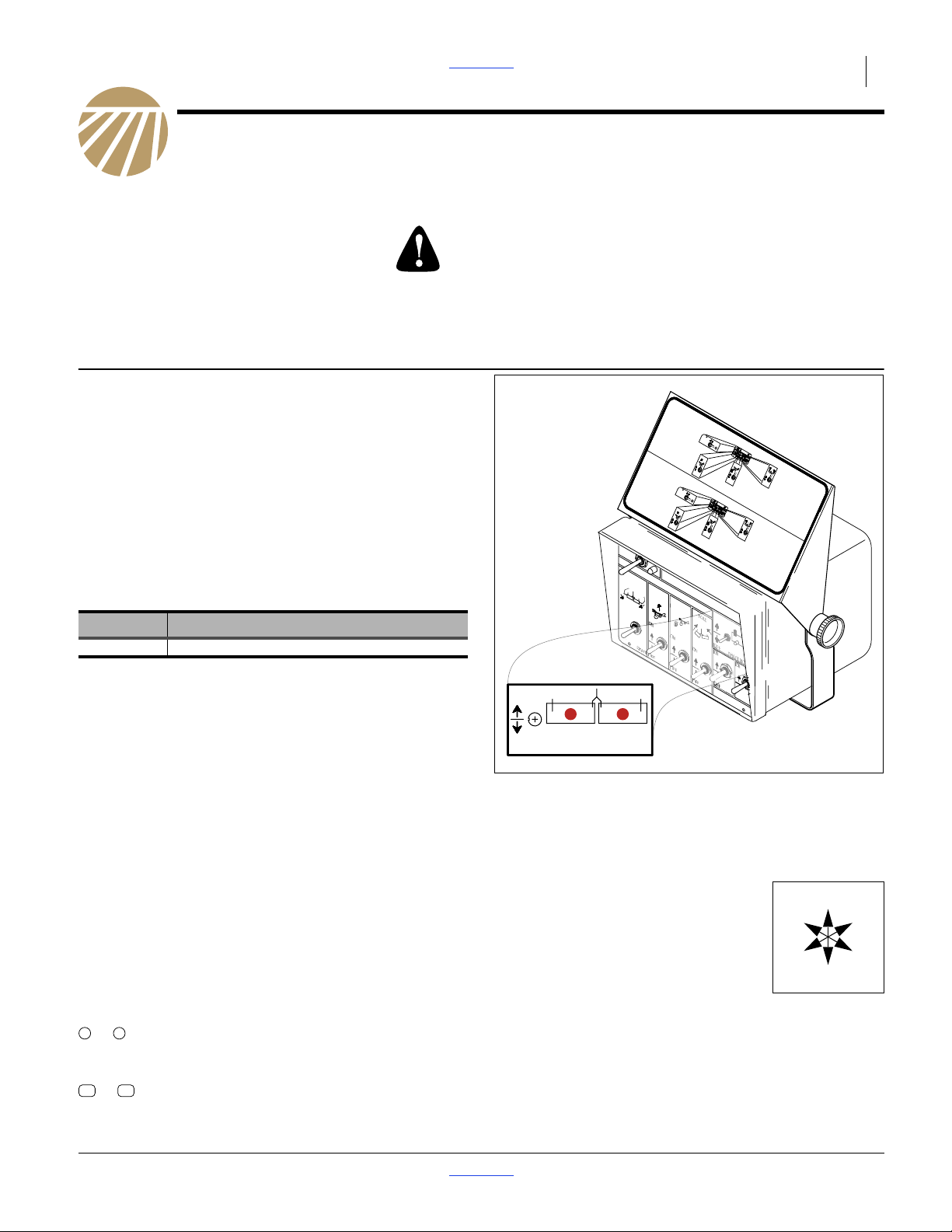
This kit provides the implement components necessary
to enable the shaft monitor function of the
electro-hydraulic console that is standard on 2SNT drills.
Refer to Figure 1
These instructions explain how to install a Two Channel
Shaft Monitor Option. The kit adds a rotation sensor to
the main seed box meter drive shaft of each drill box.
In operation, when the main seed box shaft of any drill
box stops rotating for more than 20 seconds, an alarm
sounds in the tractor cab.
One kit updates one entire drill:
Kits Kit Description
197-106A 2 CHANNEL SHAFT MONITOR KIT
Parts and Tools Required:
• Instructions for performing a calibration on this
model drill.
• Basic hand tools, and
• two people suggested for bracket installation.
Compatibility Check
ON
1. RAISE DRILL WITH GUAGE WHEEL
CYLINDERS TO FULLY EXTENDED
POSITION.
2. TURN MASTER POWER SWITCH "ON".
RAISE DRILL TO FOLD POSITION.
1. TURN MASTER POWER SWITCH "ON".
RAISE BOXES OFF TRANSPORT
"RAISE-TO-FOLD" SWITCH "ON".
CARRIERS.
MASTER
HYDRAULIC CONTROLS
MARKERS
RAISE-TO
-FOLD
LEFT
"RAISE-TO-FOLD" SWITCH "ON".
MASTER
RAISE-TO
-FOLD
ON
OFF
TRANSPORT
LOCKS
FOLDING NO-TILL DRILL
OFF ON
MASTER
RAISE-TO
-FOLD
ON
OFF
3. "RAISE-TO-FOLD" SWITCH "OFF".
"TRANSPORT LOCKS" SWITCH "ON".
EXTEND "TRANSPORT LOCK" CYLINDERS.
UNFOLDING NO-TILL DRILL
OFF
ON
OFF ON
MASTER
MARKERS
HYDRAULIC CONTROLS
Great Plains
RAISE-TO
-FOLD
TRANSPORT
LOCKS
ON
FOLD
LEFT
ON
ON
RIGHT
OFF
ON
OFF
OFF
SHAFT MONITORS
ON
OFF
ON
OFF
EFT
ELECTRIC CLUTCHES
OFF
HT
TRANSPORT
LOCKS
ON
2. "RAISE-TO-FOLD" SWITCH "OFF".
OFF
"TRANSPORT LOCKS" SWITCH "ON".
RETRACT "TRANSPORT LOCK" CYLINDERS.
ON
ELECTRIC CLUTCHES
OFF
MASTER
ON
MARKERS
HYDRAULIC CONTROLS
RAISE-TO
-FOLD
ON
LEFT
ON
RIGHT
OFF
OFF
TRANSPORT
LOCKS
ON
OFF
OFF
LEFT
OFF
Great Plains
TRANSPORT
LOCKS
FOLD
ON
ON
OFF
SHAFT MONITORS
ON
OFF
ON
OFF
EFT
ELECTRIC CLUTCHES
HTOFF
ON
OFF
REFER TO OWNERS MANUAL FOR MORE
DETAILED INFORMATION ON FOLDING AND
UNFOLDING.
FOLD
3. "TRANSPORT LOCKS" SWITCH "OFF".
ON
"FOLD" SWITCH "ON".
SLOWLY EXTEND FOLD CYLINDERS.
4. "FOLD" SWITCH "OFF".
"RAISE-TO-FOLD" SWITCH "ON".
LOWER BOXES TO FIELD POSITION.
"RAISE-TO-FOLD" SWITCH "OFF".
IF DRILL IS EQUIPPED WITH OPTIONAL
MARKERS, ELECTRIC CLUTCHES, OR
SHAFT MONITORS, REFER TO OWNERS
MANUAL FOR SWITCH OPERATIONS.
P.N. 818-508C
RI
FOLD
4. "TRANSPORT LOCKS" SWITCH "OFF".
"FOLD" SWITCH "ON".
SLOWLY RETRACT FOLD CYLINDERS.
5. "FOLD" SWITCH "OFF".
"RAISE-TO-FOLD" SWITCH "ON".
LOWER BOXES ON CARRIERS.
"RAISE-TO-FOLD" SWITCH "OFF".
SHAFT MONITORSOFF
Figure 1
36319
2 Channel Console
Refer to Figure 1
This kit is compatible with bare shafts, or shafts inside
round plastic spacer tubes between meters. It is
compatible with large 817-075C seeder cups (13⁄4inch
flute width) on the above-listed models.
Note: Paragraphs in this format provide useful
information related to the current topic.
“Left” and “Right” are facing in the
direction of machine travel. An
orientation rose in the line art
R
U
B
illustrations shows the directions of
Notations and Conventions
The following terms are used throughout this manual.
Left, Right, Front, Back, Up, Down.
F
L
D
Call-Outs
1 9
to Single-digit callouts identify components in the
currently referenced Figure. These numbers may
be reused for different items from page to page.
11
24
to Two-digit callouts in the range 11 to 23 reference
new parts from the list on page 5.
© Copyright 2014 Printed 2014-08-27 Part Lists 197-114M
Page 2
2 Great Plains Manufacturing, Inc. Front Page Part Lists 2 CHANNEL SHAFT MONITOR
Prepare the Drill
1. Clean out main seed boxes.
Possible Chemical Hazard
This installation requires contact with interior components of
the main seed box. If treated seed has ever been used in the
box, follow chemical supplier instructions for protective
equipment and cleaning residue from the seed box.
2. Move the drill to a location with adequate lighting,
and a clear surface beneath for recovery of any
fallen parts.
3. Unfold the drill. Consult the Operator manual for
details and safety considerations.
4. Raise the drill or otherwise configure it so that the
meter drive shaft may be rotated while the drill is
stationary.
5. Install all locks or supports necessary to support the
drill while it is being worked on.
6. Shut off any tractor used to position the drill and
remove the key.
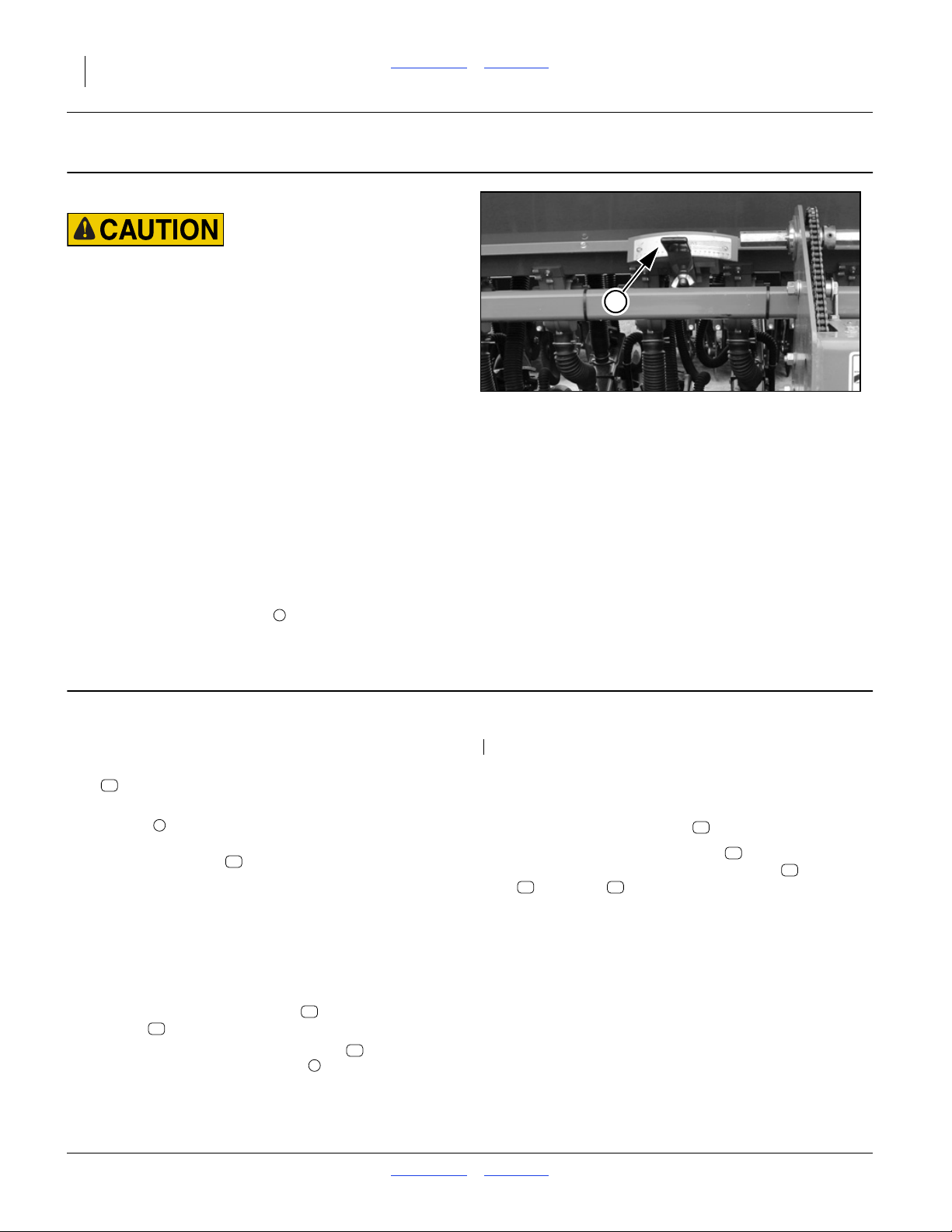
Refer to Figure 2
7. Setthe seed ratehandles ,forall main seed boxes,
1
to 50 on the 0-to-100 scales.
1
Figure 2
Set Rate Handles to 50
28066
Identify Mounting Positions
Sensor Mount Install
Refer to Figure 3 on page 3
1. Select one new:
12
116-029D, 2SNT SENSOR MOUNT
2. Find the box section between cups with the two, #8
screws , washers, and nuts already in place.
Removethe nuts and washers and use for installing
the sensor mount .
If any shaft protective tubing is installed, remove and
discard.
Make sure that the locations between cups have the
following attributes:
• not obstructed to the front by a seed rate handle, and
• there is adequate exposed surface on the drive shaft
to place the shaft monitor hose and shaft monitor
magnets .
3. Mount the end of the sensor mount with the
holes over the two, #8 screws . Make sure the
slotted-end of the mount is down and pointing
towards the front of the drill.
3
12
13
14
12
3
Notes:
Gaps with lock collars generally provide exposed shaft.
4. Install the washers and nuts removed in step 2 and
tighten the sensor mount in place.
5. Attach the reed sensor switch at the slotted end
of the bracket using two #4-40 screws , washers
17 18
, and nuts as shown in Refer to Figure 3. Do
12
15
16
not tighten screws at this time.
6. Repeat step 1 through step 4 to install the bracketin
the other main seed box.
197-114M Front Page Part Lists 2014-08-27
Page 3

Install Magnets Front Page Part Lists Great Plains Manufacturing, Inc. 3
Install Magnets
Shaft Install
13
2
3
14
Refer to Figure 3
1. De-grease and dry the seed box shaft .
2. Rotate the shaft so that two faces are vertical, and
two are horizontal.
3. Select one new:
13
197-270D SHAFT MONTITOR HOSE
4. Slip the shaft monitor hose over the shaft and
center approximately with the middle of the sensor
mount . If necessary, trim hose to fit between the
shaft lock collars.
5. Select two new:
14
6. Slip each magnet over the hose , and position
as shown in figure 3. Run each magnet clamp up
against each lock collar, then tighten the clamps.
7. Slide the reed sensor switch in the mount side-toside, and front-to-back until it is centered between
the magnets and tighten the #4-40 screws .
8. Repeat steps 1 through 7 to install the other sensor
and magnets.
12
10630171101 SHAFT MONITOR MAGNETS
14
13
15
2
2
13
16
14
18
17
12
Refer to Figure 4
• Typical installation.
15
16
Figure 3
Magnet on Shaft
Figure 4
Magnet/Sensor Clearance
R
F
U
B
L
D
34212
36404
2014-08-27 Front Page Part Lists 197-114M
Page 4

4 Great Plains Manufacturing, Inc. Front Page Part Lists 2 CHANNEL SHAFT MONITOR
Install Harness
General Harness Guidelines
• Before installing cable ties, uncoil and dress the cable
assembly and extensions across the drill and to
the hitch. This assures that the cables are long
enough, and correctly oriented left/right.
• Keep cables clear of moving parts and pinch points,
such as chains, sprockets and rotating shafts.
• Keep cables clear of sharp edges (or protect edges).
• Keep cables clear of any machine parts that get hot.
• Allow slack at hinge points, or route the cable so that it
passes through the hinge axis.
• Take advantage of holes and open tubes on the drill.
However, avoid routing through a tube if a mated
connector set would end up inside the tube.
• Evaluate routing and attachment points. Ample ties
are provided for most situations. The ties can also be
used around hydraulic hoses to secure the cable.
• Leave a little slack between attachment points.
A cable stretched taut could be damaged by normal
temperature swings.
• Where there is an extended run of unsupported cable,
makesure each end of the sag is supported by a cable
tie, and that there are no connections in the sag.
• Where excess cable exists (such as on two-point
drills), plan a location for coiling it up and securing it.
Having the coil near the hitch provides flexibility if any
later troubleshooting required.
• Before making outside connections, apply a generous
amount of dielectric grease around the inside surface
of all female (receptacle) connectors.
21 22
197-114M Front Page Part Lists 2014-08-27
Page 5

Appendix Front Page Part Lists Great Plains Manufacturing, Inc. 5
Appendix
Part Lists
New Parts
The part call-out numbers in this list match all Figures in
these installation instructions. Part descriptions match
those in your updated Parts Manual.
Kit Contents
197-106A
TWO CHANNEL SHAFT MONITOR OPTION
Quantities are units (“ea”).
Callout Number
Quantity in Kit Part Number Part Description
11 1 197-114M
12 2 116-029D
13 2 197-270D
14 4 10630171101
15 2 117-0159-964
16 4 311-0005-013
17 4 312-1001-008
18 4 313-1000-004
19 1 823-119C
20 2 063-0172-375
21 1 115-0159-661
22 2 115-0171-490
23 1 117-0159-564
a. Order replacements from Raven Industries, Inc.
24’ & 30’ SHAFT MONITOR MANUAL
2SNT SENSOR MOUNT
SHAFT MONTITOR HOSE
SHAFT MONITOR MAGNETS
a
REED SENSOR SWITCH (INCLUDES 21 & 23)
a
SCREW PHP HD 4-40 UNC-2A
a
WASHER #4 LOCK
a
NUT HEX #4 UNC-2B
2SNT SHAFT SENSOR CABLE
a
SENSOR SHAFT
SENSOR CABLE ASSSEMBLY
a
SENSOR CABLE EXTENSON 3FT
2SNT SHAFT MONITOR
2014-08-27 Front Page Part Lists 197-114M
Page 6

6 Great Plains Manufacturing, Inc. Front Page Part Lists 2 CHANNEL SHAFT MONITOR
Great Plains Manufacturing, Inc.
Corporate Office P.O. Box 5060
Salina, Kansas 67402-5060 USA
197-114M Front Page Part Lists 2014-08-27
 Loading...