

Great Plains 2600-2S User Manual
Great Plains Mfg., Inc.
Installation Instructions
2600-2S
Small Seeds Option
Used with:
2600-2S
•
General Information
These instructions explainhow to install the small-seeds attachment. The small-seeds attachment delivers the smallest seeds
evenlyand gently.The attachment holds 0.24 bushels per foot.
These instructions apply to:
• 133-164A . . . . . . . . . . . . . . . . . . . . . . . 2600 Small Seeds 6"
• 133-165A . . . . . . . . . . . . . . . . . . . . 2600 Small Seeds 7 1/2"
• 133-166A . . . . . . . . . . . . . . . . . . . . . . 2600 SmallSeeds10"
• 133-167A . . . . . . . . . . . . . . . . . . . . . . 2600F Small Seeds 6"
• 133-168A . . . . . . . . . . . . . . . . . . . 2600F Small Seeds 7 1/2"
• 133-169A . . . . . . . . . . . . . . . . . . . . . 2600F Small Seeds 10"
Assembly Instructions
Box Assembl y
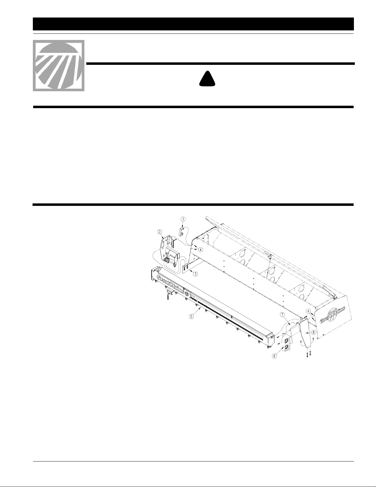
Refer to Figure 1
1. Workingon theleft-handside ofthedrill
removehandle (1) and warninglight(6)
from main seed box. Save bolts, nuts,
light and handle for later use.
2. Installtheleft-handmount and drive (2)
on the left side of drill frame (3) using a
1/2"x 11/4" bolt, 1/2"lock washerand a
1/2"nutsupplied in thekit.It will also be
necessary to remove and use the existing bolt.
3. At holes (4), where the handle was removed, fasten top of the left-hand
mount and drive (2) to main seed box.
Use 1/2" x 1 1/4" bolts and
1/2" locking flange nuts. Leave mounting hardware loose.
4. Install the right-hand mount (8) on the
right side of drill frame using a 1/2" x
1 1/4" bolt, 1/2" lock washer and a 1/2"
nutsupplied in the kit.Itwill also be necessary to remove and use the existing
bolt.
5. At holes (4), where the light was removed, fasten top of the right-hand
mount (8) to main seed box.Use 1/2" x
11/4" boltsand 1/2"locking flangenuts.
Leave mounting hardware loose.
6. Boltsmall-seeds box (5)to boxmounts.
Use 3/8" x 1" bolts, 3/8" lock washers
and 3/8" nuts.
7. Attach the warning light (6) and righthand chain guard (7) to the right mount
using bolts removedin step 1.
8. Tighten all hardware.
9. Repeat steps to assemble box on righthand drill section, mirroring box
mounts.
When you see this symbol, the subsequent instructions and
warnings are serious - follow without exception. Your life and
!
!
the lives of others depend on it!
Manual Update
Refertothedrill operator’smanualfor detailed informationon operating, adjusting, troubleshooting and maintaining the smallseeds attachment safely. Refer to the parts manual for partiden-
tification.
• 2600-2S Drill Operator’sManual . . . . . . . . . . . . . .195-200M
• 2600-2S Drill Parts Manual . . . . . . . . . . . . . . . . . . 195-200P
Definitions
Right-hand and left-hand as used in this manual are determined
byfacing the direction the machine will travelwhileinuseunless
otherwise stated.
17179
Figure 1
Mounting Box
© Copyright 2001 Printed
7/16/2002
133-170M
1
Assembly
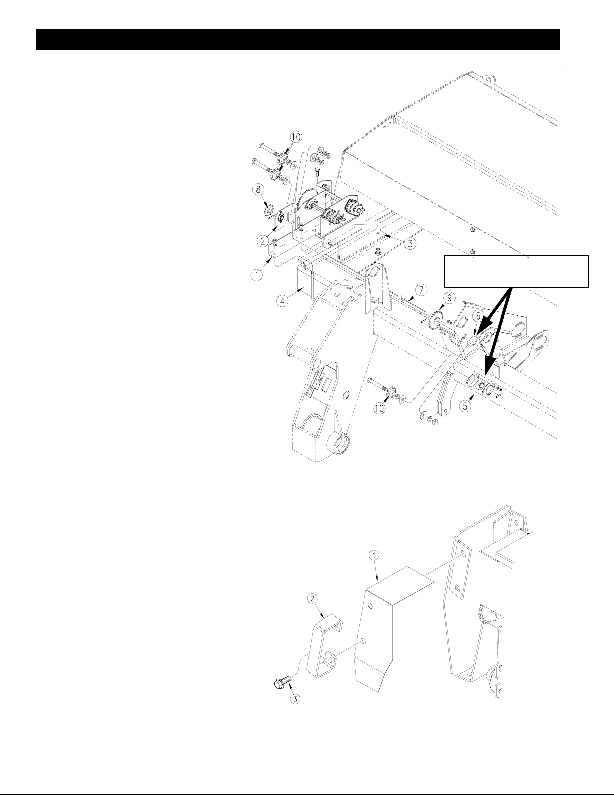
Drive Assembly (for drills without fertilizer kits)
Refer to Figure 2
1. Working on the right-hand side of the drill
mount angle channel (1) onto right-handintermediate drive (2) using 1/2" x 1 1/4" bolt, 1/2"
lock washers and 1/2" nuts.
2. Mount intermediate drive onto drill frame. Bolt
intermediate drive to side frame (3) using 1/2"
1 1/4" bolts, 1/2" lock washers and 1/2" nuts.
Fastentheintermediatedriveto frontframe(4)
Using a 1/2" x 6" x 7 1/4" U-bolt, 1/2" lock
washers and 1/2" nuts.
3. Mount bearing and flangettes (5) on open
shaft support near center of front frame (6),
see note. Use 5/16" x 1" carriagebolts, 5/16"
lock washers and 5/16" nuts to secure
flangettes to shaft support. Leave bolts loose.
4. Install new jackshaft (7) through bearings on
shaft support and bearings on intermediate
drive. As you install shaft, place 14-tooth
sprocket (8) and 23-tooth sprocket (9) on
shaft. Secure sprocketson shafts with roll
pins. When shaft and sprockets are installed
and shaft is aligned, tighten bolts on bearing
flangettes.
5. Install the three idler sprockets(10) using 1/2"
x 3" bolts, 1/2" flat washers, 1/2" lockwashers
and 1/2" jam nuts.
6. Remove old clutches and replace with the
clutches supplied in the kit.
7. Install drive chains and adjust chain tension
with the idlers.
8. Repeat steps for left-hand box.
Great Plains Mfg., Inc.
Note: Mount bearing on this side of
framebracketonly forbothrightand
left drives, do not mirror.
Drive Assembly (for drills with
fertilizer kits)
Refer to Figure 2
9. Add 14-tooth sprocket(8) to the end of jackshaft(7) and secureit inplacewith arollpin on
each side.
10. Install the two idler sprockets(10) using 1/2" x
3" bolts, 1/2" flat washers, 1/2" lock washers
and 1/2" jam nuts.
11. Route drive chain and adjust chain tension
with the idlers.
For All Drills
Refer to Figure 3
12. Install chain shields (1) over box ends. Install
handle (2) using bolts (3) that originally held
handle.
13. Repeatsteps forleft-hand box,using left-hand
intermediate drive.
18083
Figure 2
Right-Hand Drive
Figure 3
Handle and Guard
2600-2S Small Seeds Option 133-170M 3/31/04
2
Great Plains Mfg., Inc.
Assembly
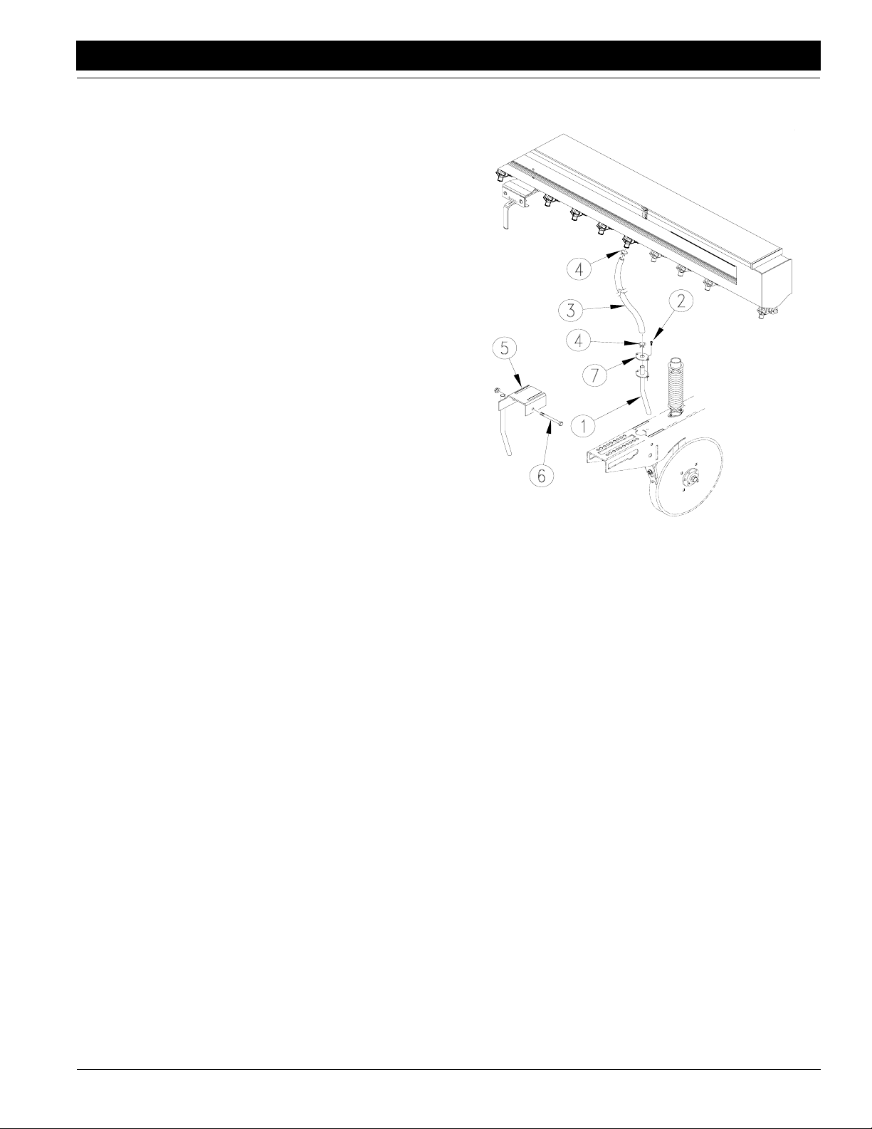
Seed Tube Assembly
Note: For drills without a fertilizer kit use seed tube P/N
123-939H and use the following instructions.
Refer to Figure 4
1. Insert the seed tube (1) into the hole on the top of the open-
er. Add reinforcement ring (7) and secure in place with a
number 10-16 x 1/2” screw (2).
2. Slidea hose clamp(4) overthe hose (3).Slidethe end ofthe
hose overthe seed tube and secureitin place with the hose
clamp.
3. Slide a hose clamp (4) over the other end of the hose and
slide the hose over the seed outlet which corresponds with
the appropriate opener. Secure hose in place with the hose
clamp.Repeat the abovestepstoinstall the rest of the seed
tubes and hoses.
Note: For drills with a fertilizer kit use seed tube P/N 133128H and use the following instructions.
Refer to Figure 4
4. Set the side delivery tube (5) downoverthe top ofthe open-
erdirectlyin front of the fertilizertube.Line up the holeswith
the holes in the opener and insert the 3/8” x 3 5/8” bolt and
secure bolt with a 3/8” lock nut flange.
5. Slidea hose clamp(4) overthe hose (3).Slidethe end ofthe
hose overthe seed tube and secureitin place with the hose
clamp.
6. Slide a hose clamp (4) over the other end of the hose and
slide the hose over the seed outlet which corresponds with
the appropriate opener. Secure hose in place with the hose
clamp.Repeat the abovestepstoinstall the rest of the seed
tubes and hoses.
Figure 4
Seed Tube and Hose
20101
3/31/04
■
2600-2S Small Seeds Option 133-170M
3

Assembly
Great Plains Mfg., Inc.
Seed Rate Calibration
NOTE: Seeding rates will v ary greatly with v ariations
in sizes of the seeds. The seeding rates listed in this
manual are based on average seed size. We recommend that you test and adjust your drill using the procedurebelowtohelp ensure an accurate seeding rate.
1. Jackup thewinggaugewheels and rotate themtosee
thatthe feedcupsand drives areworkingproperlyand
are free from foreign matter. The right wing gauge
wheeldrivesthecentersection, butthedrivedoesnot
engage unless the drill is completely unfolded.
2. Set the seed rate adjustment handle to the desired
chart setting. Make sure all the feed cup doors are in
the desired position.
3. Thereare manyfactorswhichwillaffectseedingrates:
seed treatment, weight of seed, size of seed, surface
condition of seed, tireconfiguration, tire pressure and
tire slippage. Minor adjustments will probably be
needed to compensate for these factors.
4. The pounds-per-acre in the seed rate charts are
based on the drill having 9.5L-15 6 PLY ribbed implement tires inflated to 32 psi. on the wing gauge
wheels. Check your tires forproper inflation pressure.
5. The large differences in seed size and treatment can
cause a wide variation in actual seeding rates. The
seed rate charts on the following pages are based on
averagesize seed. This may differ from the seed you
areusing.Use the seed ratecharts as a guide.Setthe
pounds per acre desired for your row spacing and
complete the following procedure to calibrate the drill
for your specific seed.
a. Place several pounds of seed overthree of the
feed cups at the outboard drive end of the drill
box.
b. Disconnect the seed tubes from these three disk
openers.
c. Lower the opener framestoplantingpositioninor-
der to activate the clutch and raise the proper
drive tire off the ground with a jackso it can be rotated by hand.
d. Place a container under the three seed tubes to
gather the seed as it is metered.
e. Rotatethedrivewheeluntiloneacre has been tal-
lied on the acremeter. This will be 203 rotations.
Be sure to check the three cups to make sure
each cup has plenty of seed coming into it.
f. Weigh the seed which has been metered. Divide
by three to get the ounces/pounds metered by
each feed cup.Multiply by the number of openers
on your drill to arrive at the total pounds-per-acre
your drill would meter at that setting. If this figure
is different than desired, set your feedcup adjustment handle accordingly.
g. Youmaywant to repeat the calibration procedure
if the results of your calibration vary greatly from
the suggested settings contained in this manual.
REMEMBER: Tire size, tire air pressure, and field conditions also affect seeding rates. When drilling, check the
amount of seed you are using by noting acres drilled,
amount of seed added to the drill, and level of seed in
each drill box. If you suspect that you are drilling more or
less than desired, you may need to adjust the seeding
rates slightly to compensate for your field conditions.
2600-2S Small Seeds Option 133-170M 3/31/04
4
■
 Loading...