

Page 1
Great Plains Manufacturing, Inc. 1
25P Eliminator Bushing Field Installation Manual
Null4:
25 SERIES OPENERS
General Information
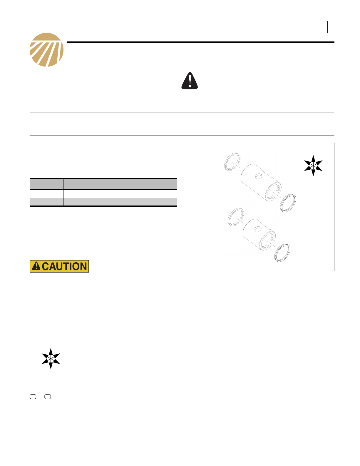
These instructions explain how to install an eliminator
bushing update kit. Order and install either narrow or
wide bushings to match with the type (narrow or wide)
opener arm on the implement. It takes two of the same
kit to update one opener:
Kit Kit Description
498-254V 25P Narrow Bushing Installation Kit
498-256V 25P Wide Bushing Installation Kit
Tools Required
• basic hand tools
When you see this symbol, the subsequent instructions
and warnings are serious - follow without exception.
Your life and the lives of others depend on it!
U
R
F
B
L
D
Work Location
Move the implement to a flat location for installation.
Sharp Object Hazard:
Be careful working near opener discs. Disc edges may be
sharp.
Notations and Conventions
Null4:
U
F
L
D
Call-Outs
11 14
to
Two-digit callouts in the range 11 to 14 reference new parts from the list on page 6.
“Left” and “Right” are facing in the
direction of machine travel. An orienta-
R
tion rose in the line art illustrations
shows the directions of Left, Right,
Front, Back, Up, Down.
B
Figure 1
25P Bushing Installation Kit
Wide (top), Narrow (bottom)
31707
© Copyright 2010 Printed 11/15/2010 498-255M
Page 2
2 Great Plains Manufacturing, Inc. Eliminator Bushing Update Kit
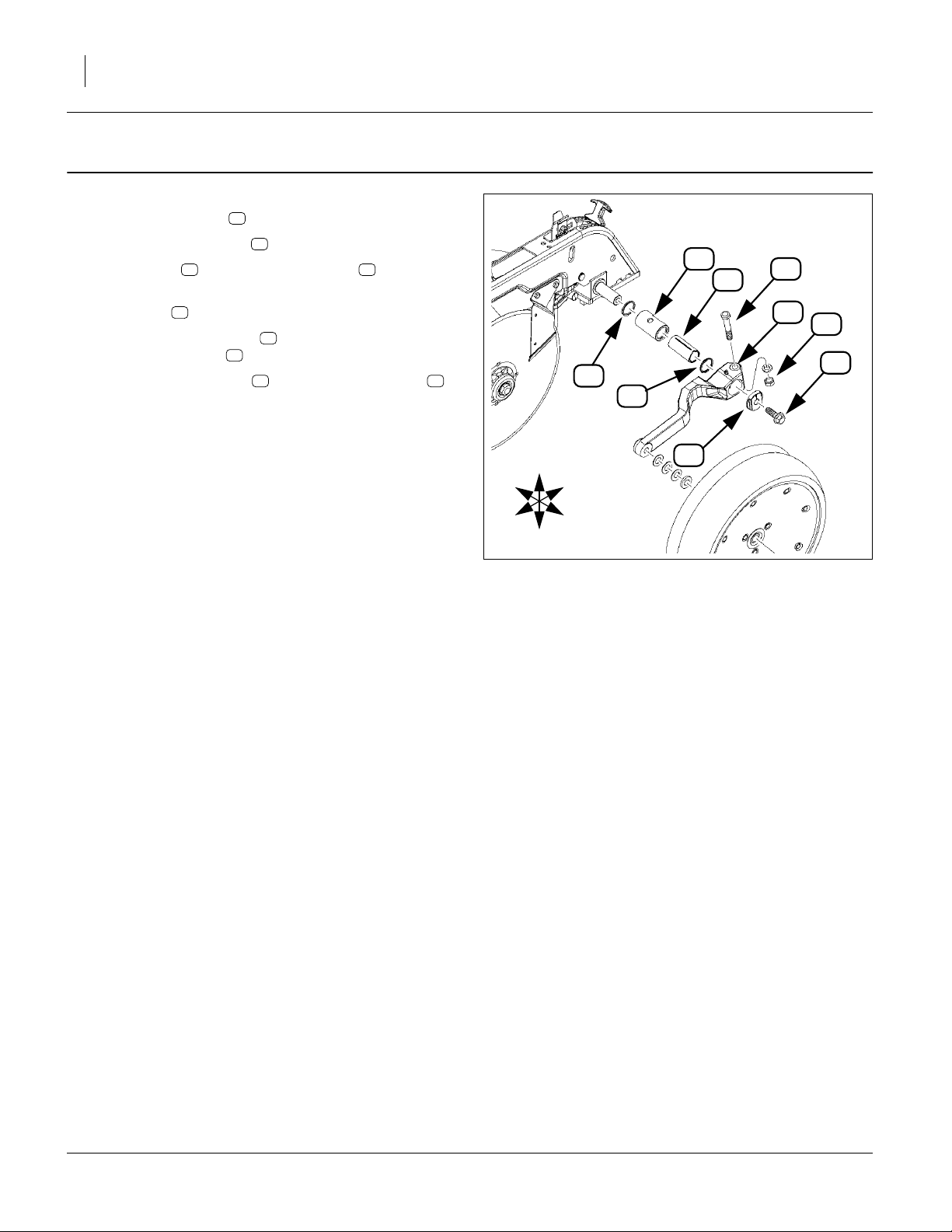
Remove Old Bushing and Seals
Refer to Figure 2
1. Remove pivot bolt . Save to reuse.
2. Remove hex adjuster . Save to reuse.
3. Loosen nut , remove hex-head bolt . Save both
to reuse.
4. Slide arm off.
5. Remove inner bushing from bushing pack.
Clean up bushing . Save to reuse.
6. Discard two old seals and old outer bushing .
38 36
34
28
32
25
25
39 40
39
39
40
25
36
34
38
28
Null4:
R
F
U
D
32
B
L
Figure 2
Remove Current Bushing
31700
498-255M 11/15/2010
Page 3

Replace with New Bushing and Seals Great Plains Manufacturing, Inc. 3
Replace with New Bushing and Seals
Refer to Figure 3 and Figure 4
Select New Outer Bushing
7. Select new outer bushing either:
Narrow:
11
198-360D OUTER BUSHING INNER CUP SEAL
or
Wide:
14
404-214D 25P O-RING BUSHING
Insert U-type Seals
Note: Do NOT damage the new seals by inserting them
in the wrong direction. If these instructions are followed the seals will not be damaged. When the
inner bushing passes through the inside of the
outer bushing it must not cut against the sealing
edge.
Note: The notch on the eccentric bushing must
face down and to the outside of opener arm.
8. Select one U cup seal .
Make sure U-shape part of seal (the open end)
faces OUT and not into the groove. Insert it in one
end of the new outer bushing . Make sure the
seal is placed securely in groove.
MAKE SURE TO ONLY INSTALL ONE SEAL AT
THIS TIME.
9. Before sliding the inner eccentric bushing into
the outer bushing put a small amount of grease
over the seal to lubricate. This makes it easier to
push the bushing through so it doesn’t damage the
seals.
10. Take the eccentric bushing flat end (not notched
24
end ) and slide it in the opposite end (end without
the seal). Push all the way through so it extends a
little past the end with the seal to allow room to get
second seal in.
11. Select second U cup seal :
Insert making sure U-shape part of seal (the open
end) faces OUT and not into the bushing groove.
Make sure it is securely in groove. Apply a small
amount of grease over the seal to lubricate.
12. Push inner bushing through this seal so it is centered inside outer bushing .
24 25
13
11
25
11
13
25
13
13
25
11
R
F
R
F
U
D
13
U
D
14
11
13
13
32
B
L
Figure 3
Replace with New Bushing
11
B
13
L
25
36
38
28
31700
25
24
Figure 4
Inner and Outer Bushings
Disassembled (top), Joined (bottom)
11/15/2010 498-255M
31699
Page 4

4 Great Plains Manufacturing, Inc. Eliminator Bushing Update Kit
Reassemble to Guage Wheel Arm
Reassemble Bushing to Arm
Refer to Figure 5 and Figure 6
13. With bushing pack all together, make sure flat
groove on outer bushing faces the back and
notch in inner bushing is to the outside of arm.
Slide pack into guage wheel arm .
14. Put hex-head bolt back through making sure it is
lined up with the flat groove in bushing .
15. Finger tighten hex-head bolt .
16. Put hex adjuster in place.
Line up notch on hex adjuster nut with notch in
eccentric bushing .
17. Reusing pivot bolt tighten finger tight.
18. Make sure bushing notch is on the bottom, this is
your starting point.
10 11
25
34
36
10 11
36
32
32
25
28
24
R
F
11
25
26
U
B
L
D
Figure 5
Bushings and Guage Wheel Arm
36
34
32
28
31700
13
R
F
10
11
U
B
13
L
D
Figure 6
Inner and Outer Bushings
Disassembled (top), Joined (bottom)
25
24
31699
498-255M 11/15/2010
Page 5

Adjust Wheel to Disc Great Plains Manufacturing, Inc. 5
Adjust Wheel to Disc
Adjusting Wheel to Disc
Refer to Figure 7 and Figure 8
Hex Head Adjuster
Check tire to disc contact location. Wheel should hit disc
at bottom of tire. At top of tire it should have3⁄8gap away
from disc. Adjust hex adjuster to obtain correct con-
tact location.
19. Move wheel arm in so side gauge wheel contacts
row unit disc at bottom. Tighten hex-head bolt to
clamp arm around bushing and shank.
Wheel and disc should touch but not be so tight
there is pressure. Pressure will cause it to bind up.
Allow for enough movement. Check wheel-to-disc
contact at 2in (5cm) planting depth. Lift wheel 2in
(5cm) and release. When let go, wheel should fall
freely.
If wheel does not contact disc at bottom to area
where blade leaves contact with soil, move hex
adjuster until wheel is angled for proper contact with
disc.
20. If wheel does not fall freely, loosen hex-head bolt
and slide wheel arm out just until wheel and arm
move freely. Retighten hex-head bolt per grade:
1
⁄2in Grade 5 bolt, 76 ft-lbs (105 N-m).
1
⁄2in Grade 8 bolt, 110 ft-lbs (150 N-m).
21. Keep turning hex adjuster and moving wheel arm
until the wheel is adjusted properly. When satisfied,
tighten pivot bolt to 110 ft-lbs.
28
32
36
36
36
Shims
Side Gauge
Wheel
Null4:
Opener
Discs
11
Correct
36
Incorrect
Figure 7
Disc/Gauge Wheel Alignment
25
Side Gauge
Wheel
34
32
28
22. If wheel does not contact blade when arm is slid into
end of bushing, then adjust the shims . Remove
shim from behind wheel to move tire closer to blade.
23. Retain removed shims by placing them on the outer
side of the gauge wheel bolt so there is always
access to them for any future adjustments.
26
R
26
U
B
Finish
24. Tighten the hex-head bolt .
25. Then tighten pivot bolt (roughly1⁄4in gap at top of
wheel).
11/15/2010 498-255M
36
28
F
L
D
Figure 8
Bushings and Guage Wheel Arm
31700
Page 6

6
Appendix
Part Lists
New Parts
The part call-out numbers in this list match all Figures in
these installation instructions. Part descriptions match
those in your updated Parts Manual.
Quantities are units (“ea”).
Kit Contents
498-254V
25P Narrow Bushing Installation Kit
Callout Quantity Part Number Part Description
11 1 198-360D OUTER BUSHING INNER CUP SEAL
12 1 498-255M 25P BUSHNG INSTALLATION MANUAL
13 2 816-686C U CUP SEAL
Kit Contents
498-256V
25P Wide Bushing Installation Kit
Callout Quantity Part Number Part Description
14 1 404-214D 25P O-RING BUSHING
15 1 498-255M 25P BUSHNG INSTALLATION MANUAL
16 2 816-686C U CUP SEAL
Great Plains Manufacturing, Inc.
Corporate Office P.O. Box 5060
Salina, Kansas 67402-5060 USA
498-255M 11/15/2010
 Loading...