

Page 1
Table of Contents Index
20- and 25-Foot 3-Point Drills
Operator Manual
2025A and 2525A
®
with Air-Pro
Manufacturing, Inc.
www.greatplainsmfg.com
Seed Meters
Read the operator manual entirely. When you see this symbol, the
subsequent instructions and warnings are serious - follow without
exception. Your life and the lives of others depend on it!
29792
Illustrations may show optional equipment not supplied with standard unit or may
depict similar models where a topic is identical.
ORIGINAL INSTRUCTIONS
© Copyright 2013 Printed 2013-06-04 118-999M
Table of Contents Index
EN
Page 2

Table of Contents Index
Table of Contents Index
Page 3

Great Plains Manufacturing, Inc. Cover Index iii
Table of Contents
Important Safety Information......................................1
Safety Decals.................................................................5
Introduction ................................................................10
Models Covered...........................................................10
Description of Unit........................................................10
Intended Usage........................................................10
Document Family......................................................10
Using This Manual........................................................10
Definitions.................................................................10
Owner Assistance ........................................................11
Preparation and Setup...............................................12
Initial Setup...................................................................12
Post-Delivery/Seasonal Setup......................................12
Pre-Planting Setup.......................................................12
Hitching Tractor to Drill.................................................13
3-Point Hitch.............................................................13
Hydraulic Hose Hookup............................................14
Protecting Fan Hydraulic Motor Seals......................14
Electrical Hookup......................................................15
Raise Parking Stands (2025A only)..........................15
Leveling the Drill...........................................................16
Leveling: Offset-Single Wheel..................................16
Meter and Row Setup...................................................18
Marker Setup................................................................18
Operating Instructions...............................................19
Pre-Start Checklist .......................................................19
Drill Weight...................................................................19
Transporting.................................................................20
Check Tractor Capacity and Configuration...............20
Remove Extra Drill Weights......................................20
Unload Seed Box .....................................................20
Secure Markers........................................................20
Transport Checklist...................................................20
Loading Seed...............................................................21
Air System Operation...................................................22
Air and Seeding System Overview...........................23
Fan Circuit Operation ...........................................24
Fan General Operating Information......................25
Butterfly Valve Operation:.....................................25
Acremeter Operation....................................................26
Normal Operating Sequence....................................26
Acremeter Programming ......................................26
Dormant Display.......................................................26
Ladder Operation .........................................................27
Monitor Operation (Option)..........................................27
Marker Operation (Option)...........................................28
Independent Marker Operation................................ 28
Single-Circuit Sequenced Marker Operation............28
Both Sides Unfolded (with Sequence Valve) .......28
Field Set-Up Checklists................................................29
Planting........................................................................30
Checking Planting Rate ............................................... 30
Short-Term Parking......................................................31
Long-Term Storage......................................................31
Adjustments ...............................................................32
Setting Planting Rate...................................................33
Seed Disk Selection and Installation........................33
Range and Transmission......................................... 33
Drive Speed Range Sprockets.............................33
Transmission Sprockets.......................................33
Shutters and Manifold Pressure...............................33
Checking Planting Rate............................................33
Marker Adjustments.....................................................34
Marker Disk Adjustment...........................................34
Fan and Adjustment.....................................................35
Furrow Check:......................................................35
Fine-Tuning (with optional Seed Monitor)................ 36
Alternate Skip/Double Check ...............................36
25AP Series Row Unit Adjustments.............................37
Row Unit Down Pressure.........................................38
Adjusting Down-Force..........................................38
Unit-Mount Cleaner Adjustments............................. 40
Coulter Adjustments.................................................41
Coulter Depth Adjustment....................................41
Coulter Row Alignment ........................................42
Row-Unit Opener Disk Adjustments.........................43
Setting Planting Depth .........................................43
Opener Disc Contact Region ...............................43
Adjusting Disc Contact.........................................43
Side Gauge Wheel Adjustment................................44
Adjusting Gauge Wheel Scrapers........................45
Seed Meter Setup and Adjustment.......................... 46
Meter Rain Cover.................................................46
Seed Inlet Shutter Adjustment .............................46
Optimal Seed Pool Slopes ...................................47
Meter Re-Fill......................................................... 47
Air-Pro® Meter Disk Installation ............................... 48
Removing a Seed Disk......................................... 49
Row Unit Shut-Off.................................................... 49
© Copyright 2009, 2010, 2011, 2013 All rights Reserved
Great Plains Manufacturing, Inc. provides this publication“as is” without warrantyofanykind,eithere xpressedorimplied.Whilee v eryprecaution has been
takeninthe preparation of this manual, Great Plains Manufacturing,Inc. assumes no responsibility forerrors or omissions. Neither is any liability assumed for
damages resulting from the use of the information contained herein. Great Plains Manufacturing,Inc. reserves the rightto revise and improve its products as
it sees fit. This publication describes the state of this product at the time of its publication, and may not reflect the product in the future.
2013-06-04 Cover Index 118-999M
Trademarks of Great Plains Manufacturing, Inc. include: Singulator Plus, Swath Command, Terra-Tine.
Registered Trademarks of Great Plains Manufacturing, Inc. include:
Air-Pro, Clear-Shot, Discovator,Great Plains, Land Pride, MeterCone, Nutri-Pro, Seed-Lok, Solid Stand,
Terra-Guard, Turbo-Chisel,Turbo-Chopper, TurboMax, Turbo-Till, Ultra-Till, Verti-Till, Whirlfilter, Yield-Pro.
Brand and Product Names that appear and are owned by others are trademarks of their respective owners.
Printed in the United States of America
Page 4

iv 2025A/2525A Table of Contents Index Great Plains Manufacturing, Inc.
Sprocket Indexing (Stagger) ................................ 52
Seed Firmer Adjustments ........................................52
Keeton Seed Firmer Adjustment..........................52
Seed-Lok
®
Seed Firmer Lock-Up ........................53
Seed-Lok® Seed Firmer Lock-Up (old style) ....... 53
Press Wheel Adjustment.......................................... 54
Press Wheel Down Pressure...............................54
Press Wheel Stagger...........................................54
Press Wheel Centering........................................55
Troubleshooting......................................................... 56
Planting Rate Problems............................................... 56
Suggested Furrow Check:.................................... 56
Seed Pool Troubleshooting..........................................57
Population Troubleshooting Charts..............................58
Maintenance and Lubrication...................................65
Maintenance ................................................................ 65
Material Clean-Out ......................................................66
Seed Box Clean-Out................................................ 66
Meter Clean-Out ......................................................66
Funnel Conversion...............................................66
Alternate Meter Clean-Out...................................67
Meter Brush Maintenance............................................68
Meter Brush Replacement .......................................69
Tufted Brush Replacement .................................. 69
Strip Brush Replacement.....................................69
Seed Disk Maintenance........................................... 70
Cleaning and Storing Seed Disks ........................ 70
Seed Tube Maintenance..............................................71
Sliding Seed Tube Replacement .............................71
Boot and Grommet Maintenance............................. 71
Chain Maintenance......................................................72
Chain Slack..............................................................72
Chain Clips............................................................... 72
Meter Drive Chain.................................................... 72
Spreaders and Scrapers..............................................73
Row-Unit Side Wheels.................................................73
Seed Flap Replacement ............................................74
Marker Maintenance.................................................... 75
Marker Shear Bolt.................................................... 75
Marker Grease Seal Cap .........................................75
Bleeding Marker Hydraulics..................................... 76
Lubrication ................................................................... 77
Seed Lubricants...........................................................80
Options ....................................................................... 81
Seed Monitor................................................................81
Speed Sensors ........................................................81
Radar Y-Cables .......................................................81
Hitch Setback Kit..........................................................82
Weight Bracket Kit ....................................................... 82
Markers........................................................................82
Seed Lubricant.............................................................83
Seed Tube Plug........................................................... 83
Lock-Up Pin..................................................................83
Unit-Mounted Row Options ..........................................84
Row Cleaners...........................................................84
Unit-Mounted Disk Coulters......................................84
Coulter Blades......................................................84
Gauge Wheel Scrapers ............................................85
Inside Disk Scrapers.................................................85
Seed Meter Disks .....................................................86
Clean-Out Container.................................................86
Seed Firmers............................................................87
Seed-Lok® Seed Firmer.......................................87
Keeton Seed Firmer..............................................87
Row Unit Press Wheels............................................87
Appendix A - Reference Information ........................88
Specifications and Capacities.......................................88
2025A Specifications and Capacities .......................88
Tire Inflation Chart........................................................88
2525A Specifications and Capacities .......................89
Torque Values Chart ....................................................90
Hydraulic Diagrams......................................................91
Fan Hydraulics (standard) ........................................91
Marker Hydraulics.....................................................92
Dual Sequenced Markers (Option) .......................92
Independent Markers (Option)..............................93
Chain Routing...............................................................94
25AP Final Meter Drive.............................................94
Ground Drive Chains................................................95
Appendix B - Initial and Option Setup......................96
Pre-Delivery Items........................................................96
Install Press Wheels.................................................96
Initial Setup...................................................................97
Seed Monitor Console Installation (Option)..............97
Speed Sensor Setup (Option)...................................97
Magnetic Sensor Gap...........................................97
Initial Marker Setup...................................................98
Marker Speed Adjustment ....................................98
Sequenced Dual Marker Speed Adjustment.........98
Independent Marker Speed Adjustment ...............98
Marker Chain Adjustment .....................................99
Marker Lifting Slack ..............................................99
Folding Slack........................................................99
Marker Transport Carrier..........................................99
Marker Extension................................................100
Marker Extension Adjustment.............................100
Marker Extension Values....................................101
Reading a Marker Extension Diagram................101
Model 2025A Marker Extension..........................101
Model 2525A Marker Extension..........................102
Option Installation...................................................104
122-278S Scraper Installation ............................104
Warranty.....................................................................105
Index ..........................................................................107
118-999M Table of Contents Index 2013-06-04
Page 5
Great Plains Manufacturing, Inc. Table of Contents Index 1
Important Safety Information
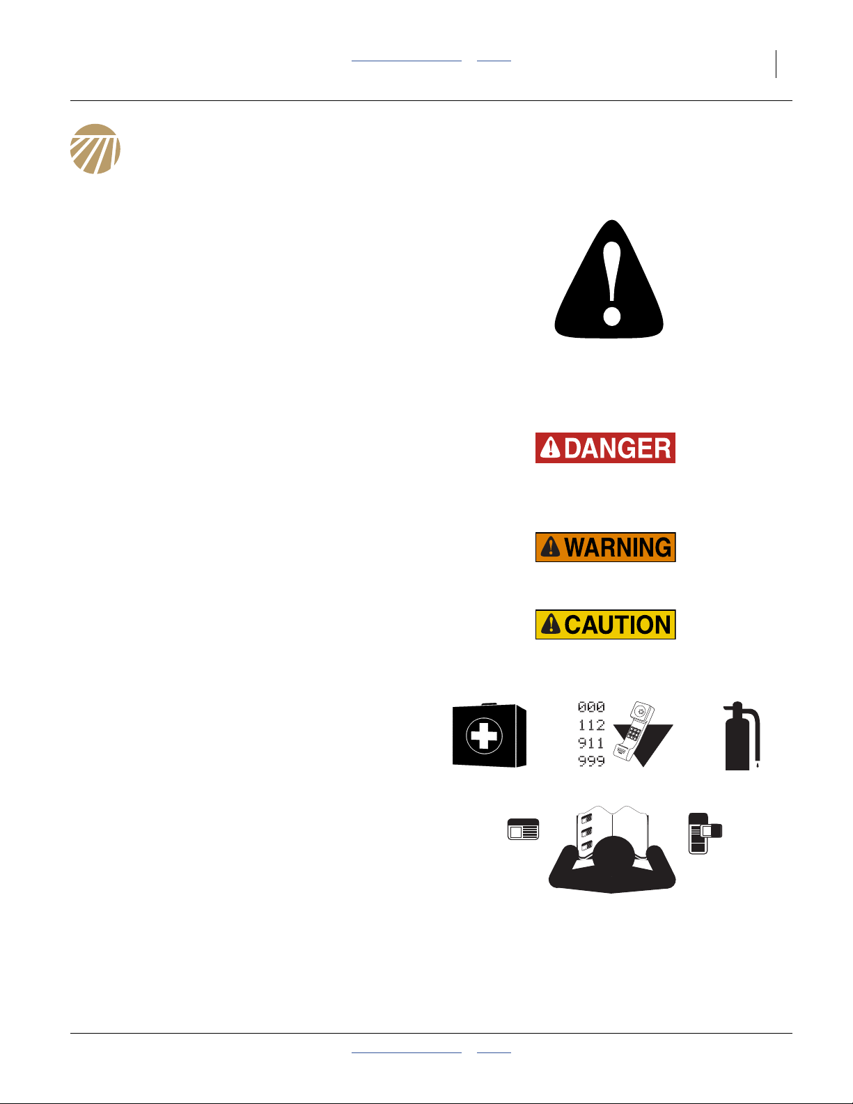
Look for Safety Symbol
The SAFETY ALERT SYMBOL indicates there is a
potential hazard to personal safety involved and extra
safety precaution must be taken. When you see this
symbol, be alert and carefully read the message that follows it. In addition to design and configuration of equipment, hazard control and accident prevention are
dependent upon the awareness, concern, prudence and
proper training of personnel involved in the operation,
transport, maintenance and storage of equipment.
Be Aware of Signal Words
Signal words designate a degree or level of hazard seriousness.
DANGER indicates an imminently hazardous situation
which, if not avoided, will resultin death or serious injury.
This signal word is limitedto themost extreme situations,
typically for machine components that, for functional purposes, cannot be guarded.
WARNING indicates a potentially hazardous situation
which, if not avoided, could result in death or serious
injury, and includes hazards that are exposed when
guards are removed.It may also be used to alert against
unsafe practices.
CAUTION indicates a potentially hazardous situation
which, if not avoided, may result in minor or moderate
injury. It may also be used to alert against unsafe practices.
Prepare for Emergencies
▲ Be prepared if a fire starts
▲ Keep a first aid kit and fire extinguisher handy.
▲ Keep emergency numbers for doctor, ambulance, hospital
and fire department near phone.
Be Familiar with Safety Decals
▲ Read and understand “Safety Decals” on page 5, thor-
oughly.
▲ Read all instructions noted on the decals.
▲ Keep decals clean. Replace damaged, faded and illegible
decals.
2013-06-04 Table of Contents Index 118-999M
Page 6

2 2025A/2525A Table of Contents Index Great Plains Manufacturing, Inc.
Wear Protective Equipment
▲ Wear protective clothing and equipment.
▲ Wear clothing and equipment appropriate forthe job. Avoid
loose-fitting clothing.
▲ Because prolonged exposure to loud noise can cause hear-
ing impairment or hearing loss, wear suitable hearing protection such as earmuffs or earplugs.
▲ Because operating equipment safely requires your full
attention, avoid wearing entertainment headphones while
operating machinery.
Handle Chemicals Properly
Agricultural chemicals can be dangerous. Improper use
can seriously injure persons, animals, plants, soil and
property.
▲ Read and follow chemical manufacturer’s instructions.
▲ Wear protective clothing.
▲ Handle all chemicals with care.
▲ Avoid inhaling smoke from any type of chemical fire.
▲ Store or dispose of unused chemicals as specified by chemi-
cal manufacturer.
Avoid High Pressure Fluids
Escaping fluid under pressure can penetrate the skin,
causing serious injury.
▲ Avoid the hazard by relieving pressure before disconnecting
hydraulic lines.
▲ Use a piece of paper or cardboard, NOT BODY PARTS, to
check for suspected leaks.
▲ Wear protective gloves and safety glasses or goggles when
working with hydraulic systems.
▲ If an accident occurs, seek immediate medical assistance
from a physician familiar with this type of injury.
Use Safety Lights and Devices
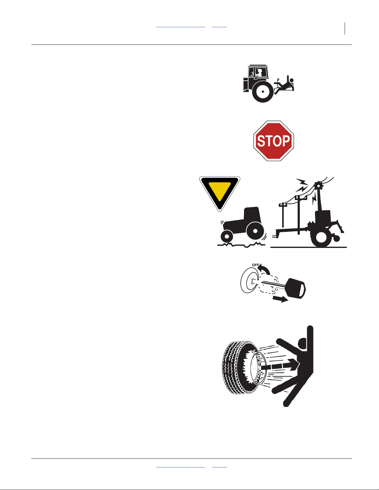
Slow-moving tractors and towed implements can create
a hazard when driven on public roads. They are difficult
to see, especially at night.
▲ Useflashing warning lights and turn signals whenever driv-
ing on public roads.
Use lights and devices provided with implement
118-999M Table of Contents Index 2013-06-04
Page 7
Great Plains Manufacturing, Inc. Table of Contents Index Important Safety Information 3
Keep Riders Off Machinery
Riders obstruct the operator’s view. Riders could be
struck by foreign objects or thrown from the machine.
▲ Never allow children to operate equipment.
▲ Keep all bystanders away from machine during operation.
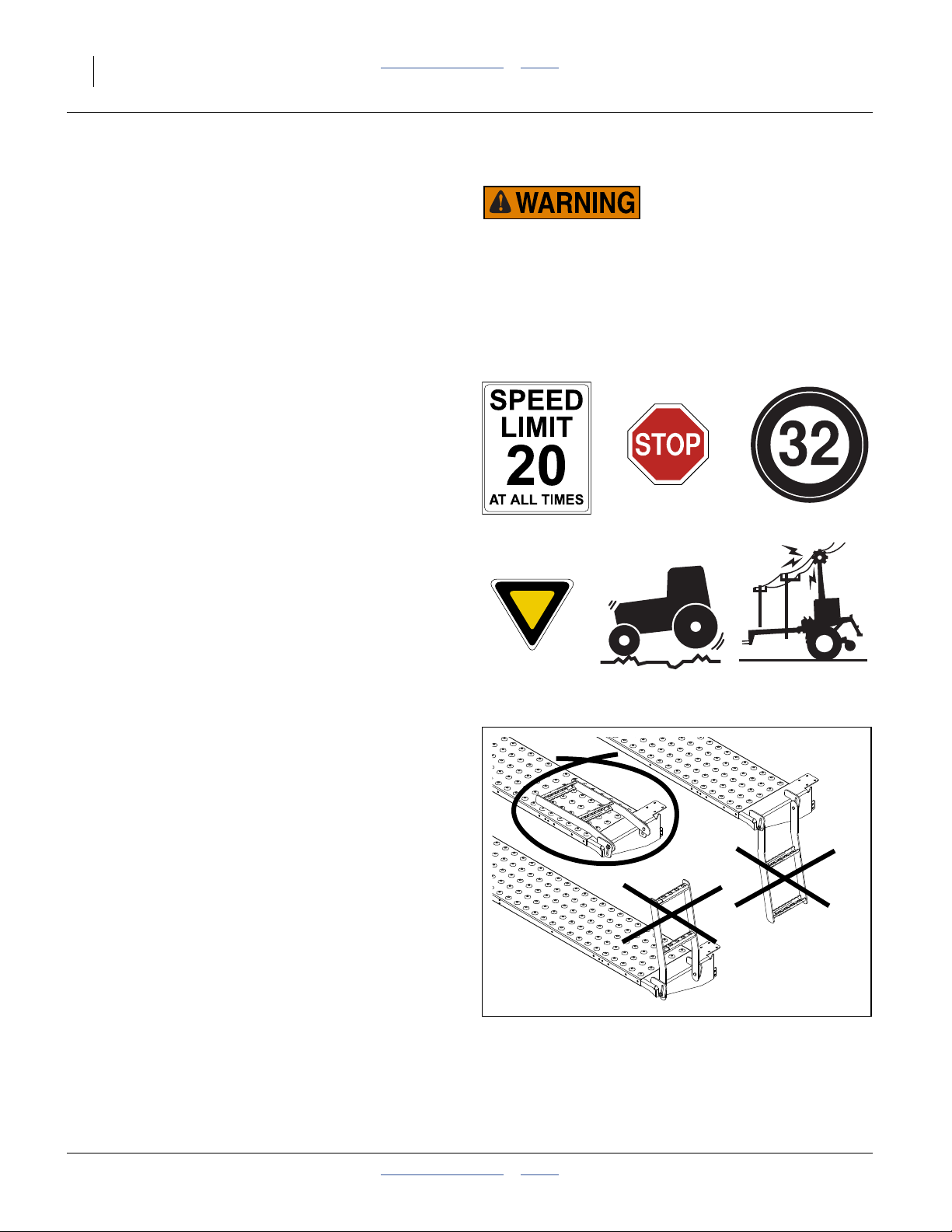
Transport Machinery Safely
Maximum transport speed for implement is 20 mph (32
kph), 13 mph (22 kph) in turns. Some rough terrains
require a slower speed. Sudden braking can cause a
towed load to swerve and upset.
▲ Do not exceed 20 mph. Never travel at a speed which does
not allow adequate control ofsteering andstopping. Reduce
speed if towed load is not equipped with brakes.
▲ Comply with state and local laws.
▲ Do not tow an implement that, when fully loaded, weighs
more than 1.5 times the weight of towing vehicle.
▲ Carry reflectors or flags to mark drill in case of breakdown
on the road.
▲ Keep clear of overhead power lines and other obstructions
when transporting. Refer to transport dimensions under
“Specifications and Capacities” on page 88.
▲ Do not fold or unfold the drill while the tractor is moving
Shutdown and Storage
▲ Lower drill, put tractor in park, turn off engine, and remove
the key.
▲ Secure drill using blocks and supports provided.
▲ Detach and store drill in an area where children normally
do not play.
Tire Safety
Tire changing can be dangerous and should be performed by trained personnel using correct tools and
equipment.
▲ When inflating tires, use a clip-on chuck and extension hose
long enough for you to stand to one side–not in front of or
over tire assembly. Use a safety cage if available.
▲ When removing and installing wheels, use wheel-handling
equipment adequate for weight involved.
2013-06-04 Table of Contents Index 118-999M
Page 8

4 2025A/2525A Table of Contents Index Great Plains Manufacturing, Inc.
Practice Safe Maintenance
▲ Understand procedure before doing work. Use proper
tools and equipment. Refer to this manual for additional
information.
▲ Work in a clean, dry area.
▲ Lower the drill, put tractor in park, turn off engine, and
remove key before performing maintenance.
▲ Make sure all moving parts have stopped and all system
pressure is relieved.
▲ Allow drill to cool completely.
▲ Disconnect battery ground cable (-) before servicing or
adjusting electrical systems or before welding on drill.
▲ Inspect all parts. Make sure parts are in good condition
and installed properly.
▲ Remove buildup of grease, oil or debris.
▲ Remove all tools and unused parts from drill before oper-
ation.
Safety At All Times
Thoroughly read and understand the instructions in this
manual before operation. Read all instructions noted on
the safety decals.
▲ Be familiar with all drill functions.
▲ Operate machinery from the driver’s seat only.
▲ Do not leave drill unattended with tractor engine running.
▲ Do not stand between the tractor and drill during hitching.
▲ Keep hands, feet and clothing away from power-driven
parts.
▲ Wear snug-fitting clothing to avoid entanglement with mov-
ing parts.
▲ Watch out for wires, trees, etc., when folding and raising
drill. Make sure all persons are clear of working area.
118-999M Table of Contents Index 2013-06-04
Page 9
Great Plains Manufacturing, Inc. Table of Contents Index Important Safety Information 5
%
%
Safety Decals
Safety Reflectors and Decals
Your implement comes equipped with all lights, safety
reflectors and decals in place. They were designed to
help you safely operate your implement.
▲ Read and follow decal directions.
▲ Keep lights in operating condition.
▲ Keep all safety decals clean and legible.
▲ Replace all damaged or missing decals. Order new decals
from your Great Plains dealer. Refer to this section for
proper decal placement.
▲ When ordering new parts or components, also request cor-
responding safety decals.
To install new decals:
1. Clean the area on which the decal is to be placed.
2. Peel backing from decal. Press firmly on surface,
being careful not to cause air bubbles under decal.
818-003C
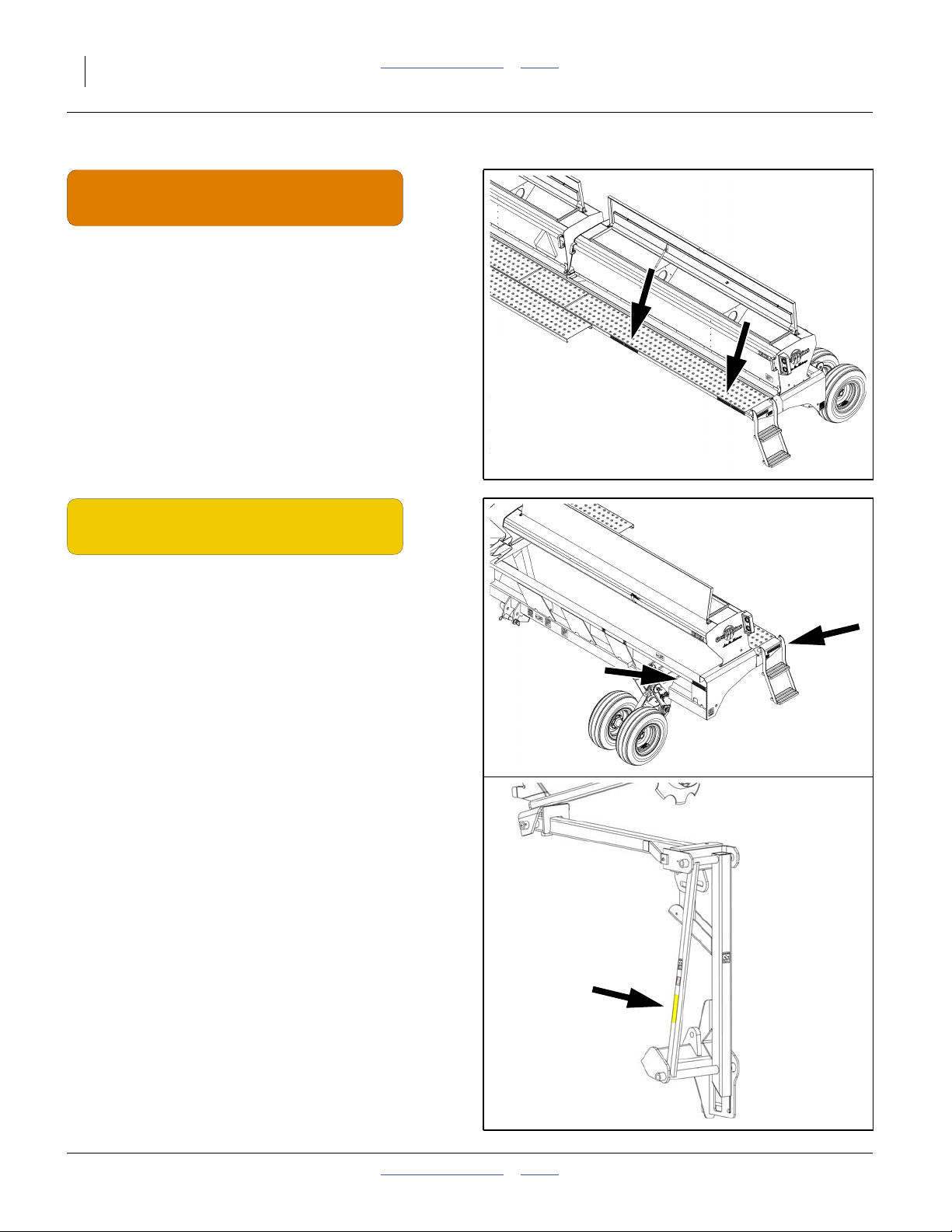
Slow Moving Vehicle Reflector
On the back of the left seed box, near drill center;
1 total
838-266C
Red Reflectors
On rear of walkboards, outside ends,
and near center of each seed box;
four total
29791_66
29791_66
2013-06-04 Table of Contents Index 118-999M
Page 10
6 2025A/2525A Table of Contents Index Great Plains Manufacturing, Inc.
%
838-267C
Daytime Reflectors
On rear of walkboards, outside ends (inboard of reds),
and near center of each seed box (inboard of reds);
four total
29791_66
838-265C
Amber Reflectors
On walkboard ends above ladders,
on the front face of the top front tool bar, outside ends;
four total
On markers (option),
front face of smaller inner arm tube;
one or two total
29791_66%
19196_33%
118-999M Table of Contents Index 2013-06-04
Page 11
Great Plains Manufacturing, Inc. Table of Contents Index Important Safety Information 7
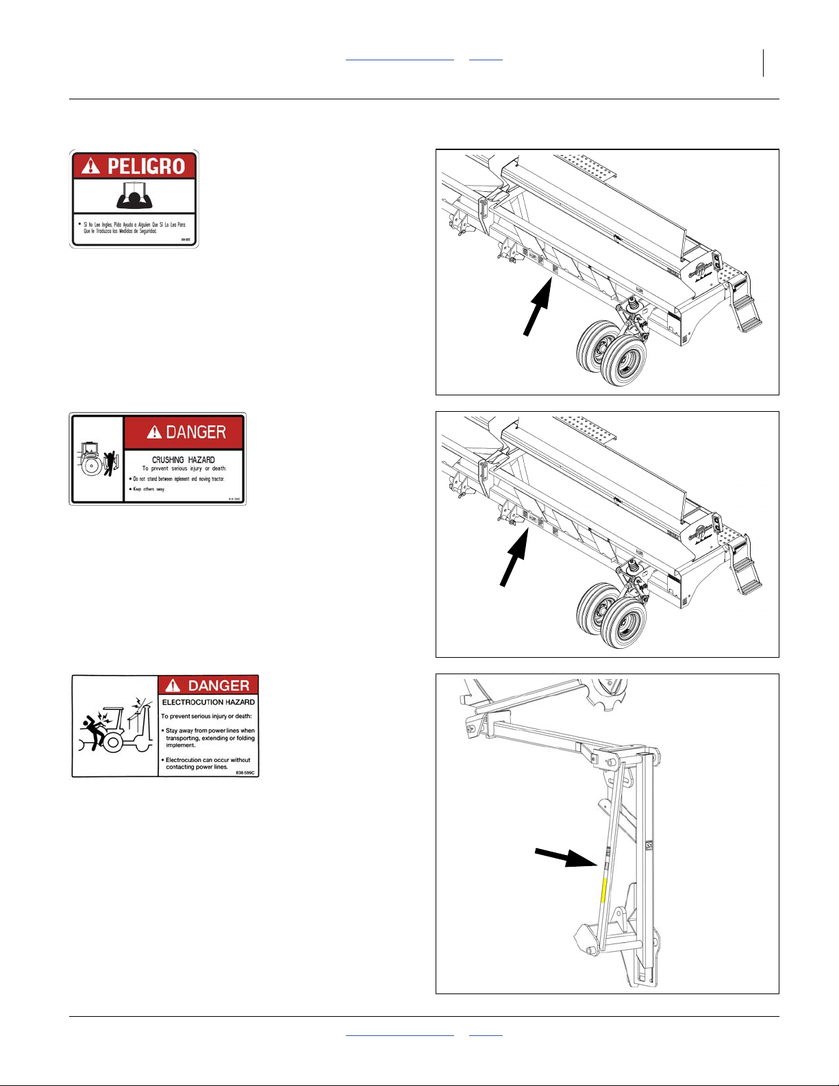
818-557C Danger (in Spanish):
Advising non-English readers to seek translation
On side of tongue; one total
29791_66%
818-590C Danger: Crushing Hazard
Front face of lower front tool bar, left of 3-point hitch;
one total
818-599C Danger: Electrocution Hazard
front face of smaller inner arm tube;
one or two total
29791_66%
19196_33%
2013-06-04 Table of Contents Index 118-999M
Page 12

8 2025A/2525A Table of Contents Index Great Plains Manufacturing, Inc.
818-682C (Option) Warning: Marker Pinch/Crush
On markers (option),
On outside face of main inner arm tube when folded,
on front face of smaller inner arm tube;
two or four total
818-337C Warning: Speed Hazard
On front of top front tool bar, left of hitch;
one total
19196_33%
29791_66%
818-339C Warning: High Pressure Fluid Hazard
On front of lower front tool bar, left of hitch;
one total
29791_66%
118-999M Table of Contents Index 2013-06-04
Page 13
Great Plains Manufacturing, Inc. Table of Contents Index Important Safety Information 9
WARNING
To avoid serious injury or death:
Watch your step when climbing ladder or
walking on walkboard.
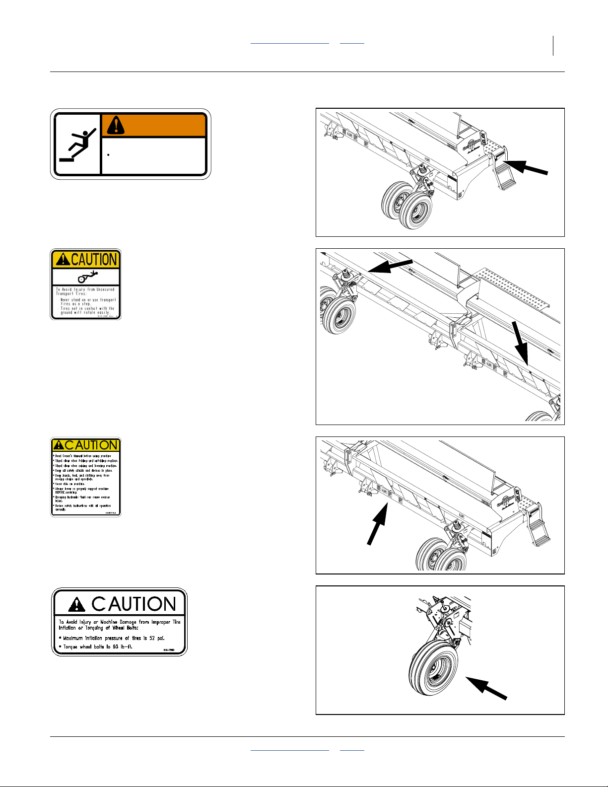
818-339C Warning: Falling Hazard
On walkboard ends, at top of ladder;
two total
838-102C
29791_66%
818-398C Caution: Tires Not A Step
On front of top front tool bar, near gauge wheels;
two total
818-587C Caution: Read Operator’s Manual
On front face of lower front tool bar, left of hitch;
one total
29791_66%
29791_66%
.tif
Standard(non-twin)
600 dpi
single is hidden
behind this mask.
818-752C (single gauge wheels) Caution: Tire Pressure and Torque
On outside rim of each wheel;
four total
2013-06-04 Table of Contents Index 118-999M
26215
Page 14
10 2025A/2525A Table of Contents Index Great Plains Manufacturing, Inc.
Introduction
Great Plains welcomes you to its growing family of new
product owners. The 20- and 25-Foot 3-Point Drills
with Air-Pro
been designed with care and built by skilled workers
using quality materials. Proper setup, maintenance, and
safe operating practices will help you get years of satisfactory use from the machine.
®
Seed Meters (2025A and 2525A) have
Models Covered
2025A-12TR36 20-Foot, 12-Row (6 Twin 8in), 36in
2025A-12TR38 20-Foot, 12-Row (6 Twin 8in), 38in
2525A-16TR36 25-Foot, 16-Row (8 Twin 8in), 36in
2525A-16TR38 25-Foot, 16-Row (8 Twin 8in), 38in
2525A-16TR3815 25-Foot, 16-Row (8 Twin 15in), 38in
2525A-16TR40 25-Foot, 16-Row (8 Twin 8in), 40in
2525A-20TR30 25-Foot, 20-Row (10 Twin 8in), 30in
Description of Unit
The 2025Aand 2525A are fully-mounted three-point precision seeding implements. The 2025A and 2525A
include 25AP Series openers with Air-Pro® meters supporting a wide choice of seed disks. The drill accepts
optional unit-mounted row accessories.
R
L
Figure 1
3-Point Drill
R
F
U
B
L
D
29792
_45%
Intended Usage
Use the 3-Pointdrill toseed production-agriculture crops
in conventional or minimum tillage conditions. Do not
modify the drill for use withattachments other thanGreat
Plains options and accessories specified for use with the
2025A and 2525A.
Document Family
118-999M Owner’s Manual (this document)
118-999B Seed Rate Charts
118-999P Parts Manual
Using This Manual
This manual will familiarize you with safety, assembly,
operation, adjustments, troubleshooting, and maintenance. Read this manual and follow the recommendations to help ensure safe and efficient operation.
The information in this manual is current at printing.
Some parts may change to assure top performance.
Definitions
The following terms are used throughout this manual.
A crucial point of information related to the pr eceding topic.
Read and follow the directions to r emain safe , avoid serious
damage to equipment and ensure desired field results.
Note: Useful information related to the preceding topic.
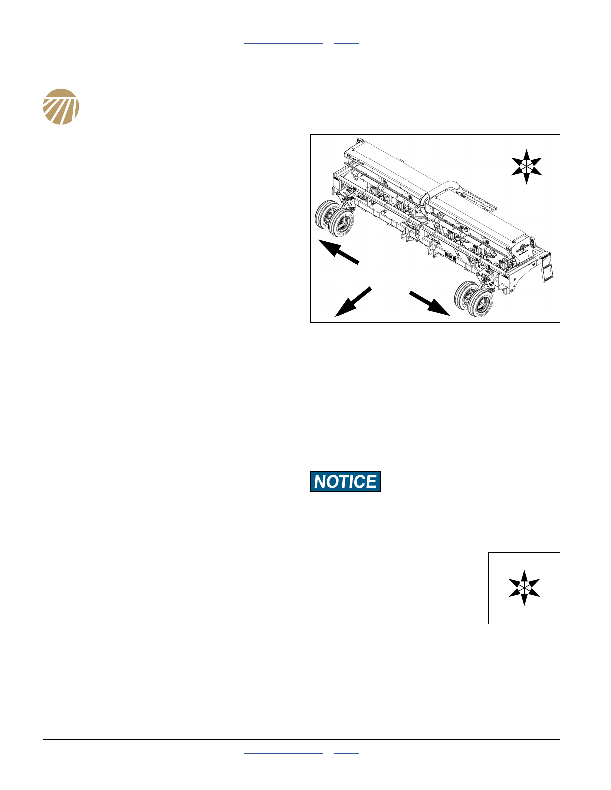
Right-hand and left-hand as used in
this manual are determined by facing
the direction the machine will travel
while in use unless otherwise stated.
An orientation rose in some line art
illustrations shows the directions of:
Up, Back, Left, Down, Front, Right.
F
R
U
B
L
D
118-999M Table of Contents Index 2013-06-04
Page 15
Great Plains Manufacturing, Inc. Table of Contents Index Introduction 11
Owner Assistance
If you need customer service or repair parts, contact a
Great Plains dealer. They have trained personnel, repair
parts and equipment specially designed for Great Plains
products.
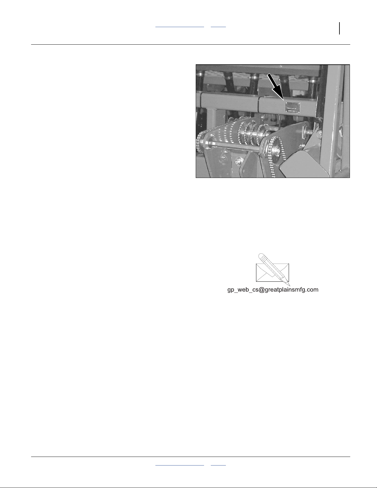
Refer to Figure 2
Your machine’s parts were specially designed and
should only be replaced with Great Plains parts. Always
use the serial and model number when ordering parts
from your Great Plains dealer.The serial-number plate is
located on the left end of the top front tool bar.
Record your 3-Point drill model and serial number here
for quick reference:
Model Number:__________________________
Serial Number: __________________________
Your Great Plains dealer wants you to be satisfied with
your new machine. If you do not understand any part of
this manual orare not satisfiedwith the service received,
please take the following actions.
1. Discuss the matter with your dealership service
manager.Make sure they areawareof any problems
so they can assist you.
2. If you are still unsatisfied, seekout theowner or general manager of the dealership.
Figure 2
Serial Number Plate
For further assistance write to:
Product Support
Great Plains Mfg. Inc., Service Department
PO Box 5060
Salina, KS 67402-5060
18307
785-823-3276
2013-06-04 Table of Contents Index 118-999M
Page 16

12 2025A/2525A Table of Contents Index Great Plains Manufacturing, Inc.
Preparation and Setup
This section helps you prepare your tractor and 2025A
and 2525A Drill for use, and covers tasks thatneed to be
done seasonally, or when the tractor/drill configuration
changes.
Before using the drill in the field, you must hitch it to a
suitable tractor, inspect systems and level the drill.
Before using the drill for the first time, and periodically
thereafter, certain adjustments and calibrations are
required.
Initial Setup
See “Appendix B - Initial and Option Setup” on
page 96 for pre-delivery items (normally completed by
dealer), and first-time/infrequent setup tasks, including:
• (Marker option) adjust marker extension and speed
(page 98).
• (Option) install seed monitor console in tractor
(page 97).
Post-Delivery/Seasonal Setup
On initial delivery,use witha new tractor, andseasonally,
check and as necessary, complete these items before
continuing to the routine setup items:
• (Marker option) bleed hydraulic system (page 72).
• (Option) radar calibration (separate manual).
• (Marker option) de-grease exposed cylinder rods if so
protected at last storage.
Pre-Planting Setup
Complete this checklist before routine setup:
❑ Read and understand “Important Safety Informa-
tion” on page 1.
❑ Check that all working parts are moving freely, bolts
are tight, and cotter pins are spread.
❑ Check that all grease fittings are in place and lubri-
cated. See “Lubrication” on page 77.
❑ Check that all safety decals and reflectors are cor-
rectly located and legible. Replace if damaged. See
“Safety Decals” on page 5.
❑ Inflate tires to pressure recommended and tighten
wheel bolts as specified. See “Tire Inflation Chart”
on page 88.
28341
118-999M Table of Contents Index 2013-06-04
Page 17
Great Plains Manufacturing, Inc. Table of Contents Index Preparation and Setup 13
Hitching Tractor to Drill
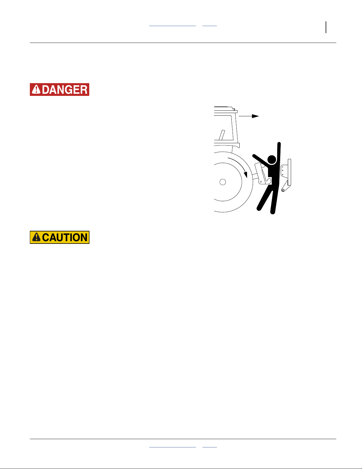
3-Point Hitch
Crushing Hazard:
Do not stand or place any body part between planter andmoving tractor. You may be severely injured or killed by being
crushed between the tractor and planter. Stop tractor engine
and set parking brake before attaching cables and hoses.
1. Raise or lower tractor three-point arms as needed
and pin lower arms to drill.
2. Pin upper arm to drill. For category III and III-N tractors, install hitch pin in the lower hole. For category
IV-N tractors, install hitch pin in the upper hole.
3. Slowly raise drill. Watch for cab interference.
4. Adjust top three-point link so that top edge of drill
box is parallel with ground when drilling.
Note: Do notuse linkto adjust openerdepth. For opener
adjustments, refer to page 43.
5. Set your tractor three-point-draft control to float position.
Load Sway Hazard:
Adjust 3-point hitch arms and sway blocks to minimize any
side-to-side sway to assure proper tracking in the field, and
safe road travel.
2013-06-04 Table of Contents Index 118-999M
Page 18
14 2025A/2525A Table of Contents Index Great Plains Manufacturing, Inc.
Hydraulic Hose Hookup
Great Plains hydraulichoses are color coded to help you
hookup hoses to your tractor outlets. Hoses that go to
the same remote valve are marked with the same color.
Color Hydraulic Function
Black Fan (3 hoses)
Green Markers
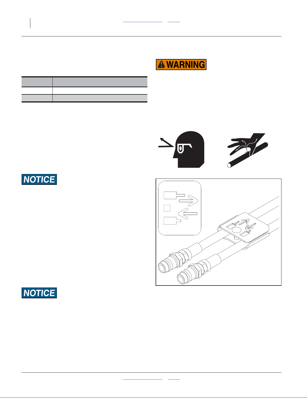
Refer to Figure 3
To distinguish hoses on the same hydraulic circuit, refer
to hose label. The hose under an extended-cylinder symbol feeds a cylinder base end. The hose under a
retracted-cylinder symbol feeds a cylinder rod end.
For the hydraulic motor, connect the hose under the
retracted cylinder symbol to the pressure side of the
motor. Connect the hose under the extended cylinder
symbol to the return side of the motor.
The fan motor further requires hookup of a third line,
which returns hydraulic fluid from the fan motor case.
High Pressure Fluid Hazard:
Relieve pressure before disconnecting hydraulic lines. Use
paper or cardboard, NOT BODY PARTS, to check for leaks.
Wear protective gloves and safety glasses or goggles when
working with hydraulic systems. Escaping fluidunder pressure
can have sufficient pressure to penetrate the skin causing serious injury. If an accident occurs, seek immediate medical
assistance from a physician familiar with this type of injury.
Only trained personnel should work on system hydraulics.
Machine Damage Risk:
Case Drain Hose must be attached first,
prior to inlet and return hoses being connected.
Case Drain Hose must be detached last,
to prevent damage to the fan motor.
Protecting Fan Hydraulic Motor Seals
Low Pressure (Case) Drain Connection
1. Attach case drain hose to low pressure drain connection.
Note: Case drain hose has the smaller1⁄4in I.D. hose
and small, flat-face, connector.
2. Connect low pressure motor return hoseto low pressure return connector. It is distinguished by a large
(1.06in/2.7cm diameter) quick coupler.
Machine Damage Risk:
DO NOT connect the case drain line to a
power-beyond-port.
3. Connect hydraulic hoses to tractor remotes.
Figure 3
Marker Hose Label
27270
118-999M Table of Contents Index 2013-06-04
Page 19
Great Plains Manufacturing, Inc. Table of Contents Index Preparation and Setup 15
Electrical Hookup
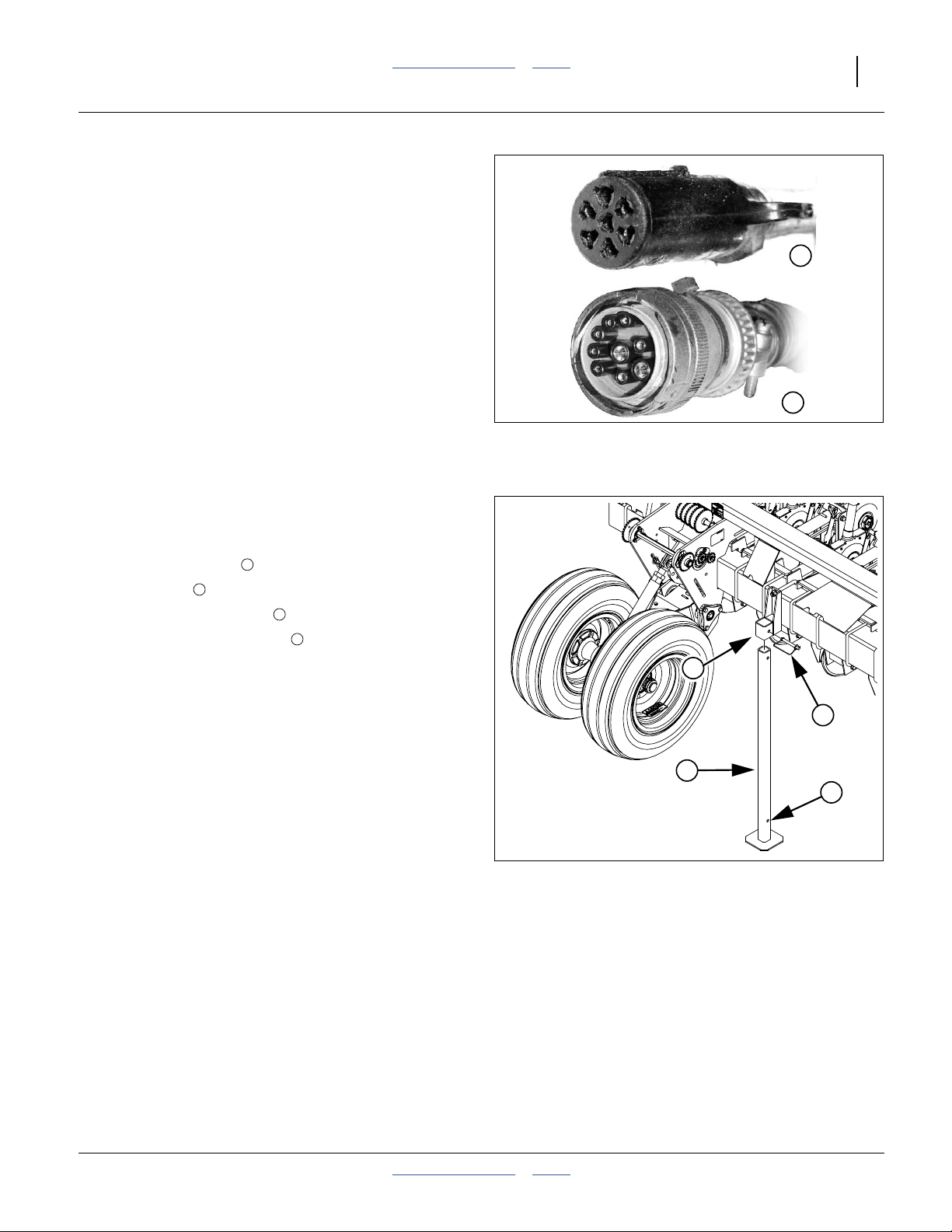
Refer to Figure 4
Make sure tractor isshut down with accessory power off
before making connections.
1. Mate lighting connector to tractor outlet.
2. Option: mate monitor connector to tractor harness.
3. Mate any accessory or aftermarket electrical connectors.
Make connections prior to drill movement. Some drill
hydraulic circuits are under monitor control.
1
2
Raise Parking Stands (2025A only)
Refer to Figure 5
1. Use tractor 3-point to raise drill enough to relieve
weight from stands .
2. Remove pin .
3. Slide stand up in mount .
4. Re-pin at lower stand hole .
4
3
5
6
Figure 4
Connector Identification
5
3
Figure 5
Model 2025A Parking Stand
25236
25237
4
6
26221
2013-06-04 Table of Contents Index 118-999M
Page 20
16 2025A/2525A Table of Contents Index Great Plains Manufacturing, Inc.
Leveling the Drill
For proper operation, and maximum compensation for
varying ground conditions, the openerparallel armsneed
to be parallel to slightly up-hill in normal lowered field
operation. This is controlled by two factors:
• the opener tool bar height, which is controlled by
adjustments to the gauge wheels, and;
• front-to-back level, which is controlled by the 3-point
hitch.
The procedure for setting initial drill height and checking
front-to-back level is:
1. Set gauge wheel adjustments to bedded or non-bed-
ded, via turnbuckle or link and block.
2. Lower drill onto gauge wheels with 3-point.
Set circuit to Float.
3. Adjust 3-point to recommended initial opener tool
bar height.
4. Verify front-to-back level, and adjust with 3-point.
Re-check height.
Make the same adjustmenton both gauge wheel assemblies.
Check that drill is still level side-to-side after setup.
Leveling: Offset-Single Wheel
The offset-single gauge wheel adjusts for bedding by
changing the turnbuckle length.
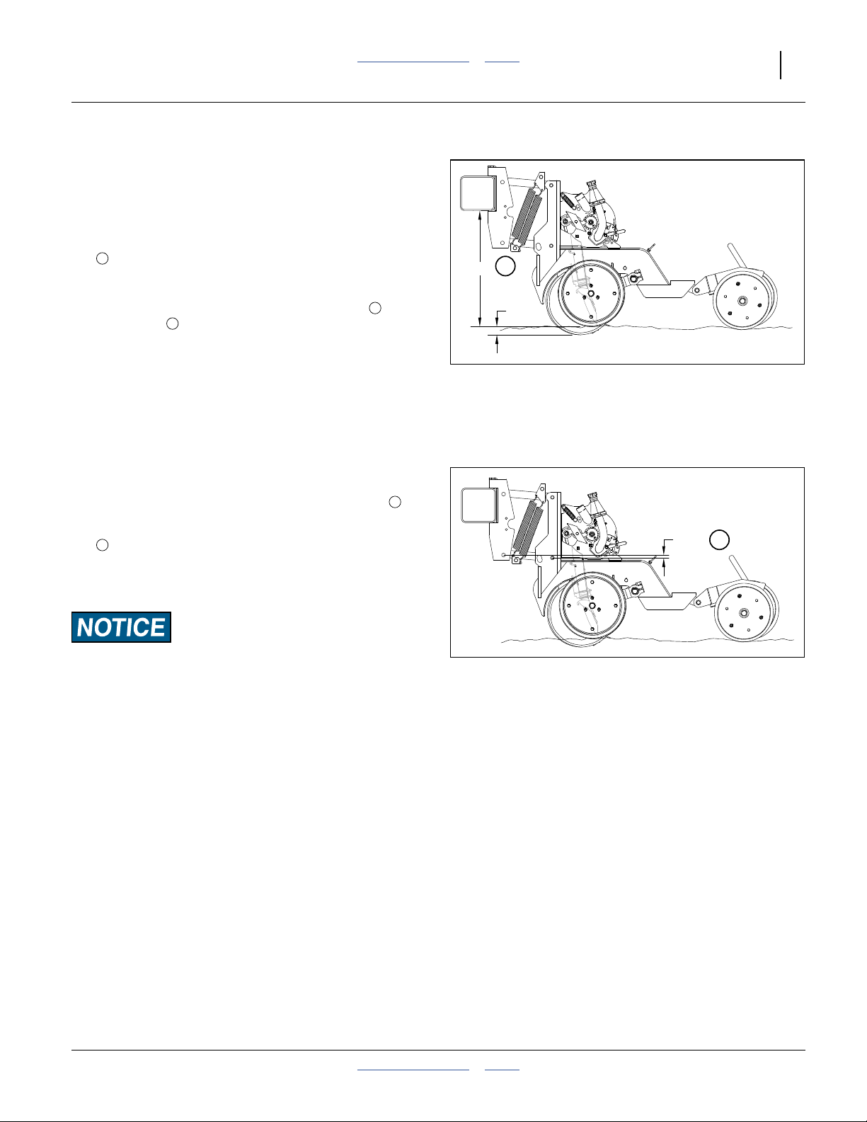
Refer to Figure 6
1. Check the link length. The factory setting for link
1
4
26in
1
171⁄2in
length , measured at center-lines, is:
This corresponds to an opener tool bar height of:
This is for non-bedded planting.
To adjust the drill for bedded planting:
2. Hitch it to a suitabletractor.Move it torepresentative
bedded ground, with the wheels between beds.
3. Lower the drill toplanting position andset the3-point
hitch circuit to Float.
2
3
Figure 6
Offset-Single Wheel Turnbuckle
1
27221
118-999M Table of Contents Index 2013-06-04
Page 21
Great Plains Manufacturing, Inc. Table of Contents Index Preparation and Setup 17
Refer to Figure 7
Note: This presumes a planting depth of 1.75in. If your
depth is different, re-adjust the tool bar height
when adjusting the press-wheels (page 54).
4. Adjust drill distance between bottom of opener tool
bar and planting ground (bed tops):
Tool bar height 26in (66cm)
4
26in
4
Refer to Figure 6 on page 16
5. To adjust turnbuckle length, loosen jam nut . Turn
turnbuckle to shorten or lengthen as necessary.
3
2
13/4in
When adjusting the turnbuckle length, remember:
+ Lengthening turnbuckle raises drill.
- Shortening turnbuckle lowers drill.
Re-tighten jam nut when height is final.
Figure 7
Offset-Single Wheel Height
29820
Note: Do not expose more than 3in (7.6cm) of thread at
either end of turnbuckle.
6. Level drill with top three-point link.
Refer to Figure 8
7. Level drill with top of three-point link. Adjust so that
row units are inclined slightly uphill, measured at
5
the ends of the parallel arms:
1 inch
Arm inclination 1in maximum
5
5
The 1in dimension shown is a general dimension that
varies with planting conditions.
Equipment Damage/Planting Depth Risks:
Ensure the opener mount is running higher than the opener
body. This ensures ample reserve for opener up-float if the
opener strikes a rock or other object.
Figure 8
Offset-Single Wheel Opener Level
29821
2013-06-04 Table of Contents Index 118-999M
Page 22
18 2025A/2525A Table of Contents Index Great Plains Manufacturing, Inc.
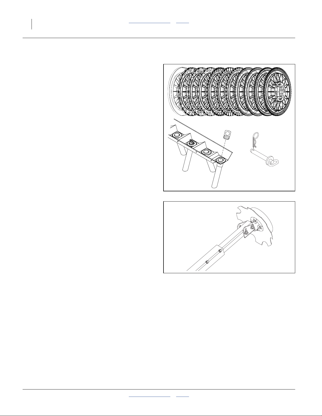
Meter and Row Setup
❑ Select and install correct seed disks forcrop, popula-
tion and desired field speed.
See Seed Rate Manual for disk selection criteria.
See page 48 for disk installation.
If planting at a non-standard row spacing:
❑ Have blank seed disks (page 86) available for bal-
ancing meter pressureat unusedrows, andreducing
meter brush wear.
See page 50 for disk installation.
❑ Have seed tube plugs (page 50) available for block-
ing seed flow to unused rows.
29594
See page 49 for plug installation.
❑ If planting at a non-standard row spacing, have
lock-uppins (page 83)availablefor reducing wear on
unused rows.
See page 51 for row lock-up.
Marker Setup
Prior to first use, check and adjust:
•“Marker Speed Adjustment” on page 98.
Prior to first use, and whenever changing row spacings,
set or reset:
•“Marker Extension” on page 100.
Prior to each planting session, check and adjust:
•“Marker Chain Adjustment” on page 99
•“Marker Disk Adjustment” on page 34.
27226
26226
118-999M Table of Contents Index 2013-06-04
Page 23
Great Plains Manufacturing, Inc. Table of Contents Index 19
Operating Instructions
This section covers general operating procedures. Experience, machine familiarity, and the following information
will lead to efficient operation and good working habits.
Always operate farm machinery with safety in mind.
Pre-Start Checklist
Perform the following steps before transporting the
3-Point drill to the field.
❑ Carefully read “Important Safety Information” on
page 1.
❑ Install seed disks appropriate for crop. See
“Air-Pro® Meter Disk Installation” on page 48.
❑ Lubricate drill as indicated under “Lubrication” on
page 77.
❑ Check all tires for proper inflation. See “Tire Infla-
tion Chart” on page 88.
❑ Check all bolts, pins, and fasteners. Torque as
shown in “Torque Values Chart” on page 90.
❑ Check drill for worn or damaged parts. Repair or
replace parts before going to the field.
❑ Rotate both gauge wheels to see that the drive and
meters are working properly and free from foreign
material.
❑ Check hydraulic hoses, fittings, and cylinders for
leaks. Repair or replace before going to the field.
High Pressure Fluid Hazard:
Relieve pressure before disconnecting hydraulic lines. Use a
piece of paper or cardboard, NOT BODY PARTS, to check for
leaks. Wear protective gloves and safety glasses or goggles
when working with hydraulic systems. Escaping fluid under
pressure can have sufficient pressure to penetrate the skin
causing serious injury. If an accident occurs, seek immediate
medical assistance from a physician familiar with this type of
injury.
Drill Weight
You need to know the weight of your drill, for safe transport, and to assure optimal field operations.
The table below shows typical weights for various models and configurations, with and without seed loaded.
If the ratings for your tractor are marginal, have your drill
weighed at a scale.
Approximate¹ Weights of
Typical Drill Configurations
Empty Drill (standard)
Base Drill with Full Seed Load
Empty Drill (w/options²)
Optioned Drill, Full Seed Load
¹ Weight of your drill weight can vary by hundreds of pounds depending on installed features.
² With Dual Markers, Unit-Mount Coulters and full Weight Kits
2013-06-04 Table of Contents Index 118-999M
2025A 2525A 2525A
-12TR36, -16TR36, -16TR38, -20TR30
-12TR38 -16TR3815, -16TR40
5520 lbs. 7360 lbs. 8200 lbs.
8400 lbs. 10600 lbs. 11440 lbs.
7752 lbs. 9847 lbs. 10847 lbs.
10632 lbs. 13087 lbs. 14087 lbs.
Page 24
20 2025A/2525A Table of Contents Index Great Plains Manufacturing, Inc.
Transporting
Fortransporting with drillattached to ahitch, refer toyour
hitch operator’s manual.
Check Tractor Capacity and Configuration
3-point implements can dangerously reduce weight on
tractor steering wheels.
• Know the transport weight of your drill (see table on
previous page).
• Consult your tractor manual for 3-point limitations.
• Add weights to tractor as required.
When determining the weight of your drill, be sure to
include the weight of any seed loaded and row options.
Remove Extra Drill Weights
Remove weights from optional weight brackets. Move
weights to tractor as needed for ballasting.
Loss of Control Hazard:
Use a tractor rated for theload. Addtractor ballast as needed.
Do not exceed 20 mph. Towing the drill with a vehicle that is
not adequate, or at high speeds, could lead to loss of vehicle
control. Loss of vehicle can result in a serious road accident,
severe injury or death. Check that your tractor has enough to
handle the weight of the drill. Refer to your tractor’s operator
manual for capacities and ballast requirements.
Unload Seed Box
Unload seed box before transporting if at all possible.
See “Material Clean-Out” on page 66.
The drill can be transported with a full box of grain, but
the added weight will increase stopping distance and
decrease maneuverability.
To maintain steeringcontrol, you may need toadd ballast
to your tractor front end. Refer to your tractor operator’s
manual for ballast required.
Secure Markers
Always transport markers in the folded position and
marker hydraulic circuit(s) in neutral (to prevent unintended marker movement in cradles).
Transport Checklist
❑ Plan the route. Avoid steep hills.Keep Clearances in
mind.
❑ Hitch: Make all electrical and hydraulic connections.
See “Hitching Tractor to Drill” on page 13.
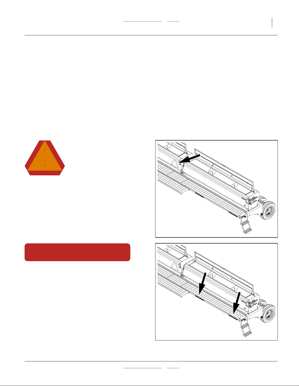
Refer to Figure 9
❑ Fold up walkboard ladders for maximum clearance.
❑ Fold markers. Lock circuit with Neutral setting.
See “Marker Operation (Option)” on page 28.
❑ Raise drill.
❑ Close all seed inlet shutters if transporting with seed.
❑ Always have lights on for highway operation.
❑ Comply with all federal, state and local safety laws
when traveling on public roads.
❑ Travel with caution. Allow safe clearance.
Remember that the drill is wider than the tractor.
Figure 9
Walkboard Ladder for Transport
28828
118-999M Table of Contents Index 2013-06-04
Page 25
Great Plains Manufacturing, Inc. Table of Contents Index Operating Instructions 21
Loading Seed
Watch your step when walking on drill ladder and walkboard. Falling from drill could cause severe injury or
death.
Great Plains recommends loadingmaterials afterthe drill
has been transported to the planting ground.
Seed is heavy.
Pre-loading substantially increases transport hazards:
• Stopping distance increases.
• The center of gravity moves aft:
Tractor steering wheels have less weight on them,
reducing steering effectiveness.
• Turning hazards increase:
Even with effective steering, turns are more difficult to
initiate and more difficult to stop, due to the inertia of
the wide load.
To load materials:
1. Load only in dry conditions.
2. If the seed is treated, wear protective equipment rec-
ommended for the hazards.
3. If loading seed prior to transport, close all seed inlet
shutters (page 46).
4. Lower the drill.
Refer to Figure 10
5. Fold down the ladders.
6. Open the lids for the boxes. Handle is also a latch,
pull out and up to release.
7. Remove any debris or obstructions from the boxes.
8. If planting at a non-standard row spacing, insert
seed plugs in unused rows (page_page 50).
9. Load seed.
Agricultural Chemical Hazard:
Follow seed supplier and chemical manufacturer instructions
for treated seed. Avoid contact with skin or eyes. Avoid breathing dust or fumes - use a respirator. Know what to do if an
accident occurs.
Equipment Damage/Population Risk:
Do not use liquid seed treatments. Pre-treat and dry seed
before loading. Excessively sticky seed does not meter reliably.
Population Risk:
Seed lubricant is required. All seed must be mixed with Ezee
Glide Plus seed lubricant. See page 80.
WARNING
To avoid serious injury or death:
Watch your step when climbing ladder or
walking on walkboard.
838-102C
Mix seed lubricant as you load (page 80).
Load or spread seedevenlyacross all partitions.Use
a tool or gloved hand.
10. Make a note of the quantity loaded, for later confir-
mation of population or application density desired.
Note also the acremeter reading.
11. Close and latch the box lids.
12. Raise the ladders (page 27).
Figure 10
Walkboard Ladder for Loading
28828
Before the firstplanting each season, orwhen using new
meters or meter wheels for thefirst time, orat the start of
each season, before filling with seed, add
<numerator>1⁄<denominator>3 cup Ezee Glide Plus
seed lubricant to bottom of seed box.
2013-06-04 Table of Contents Index 118-999M
Page 26
22 2025A/2525A Table of Contents Index Great Plains Manufacturing, Inc.
Air System Operation
15
14
3
2
1
5
6
7
8
13
4
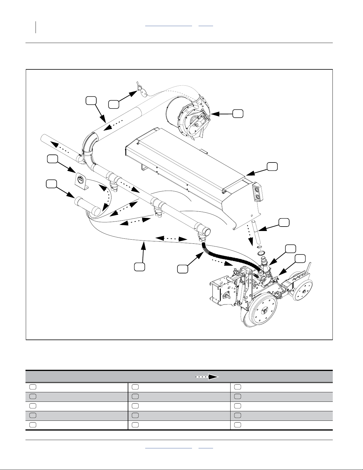
Figure 11
Drill Air System for Air-Pro® Seed Metering
29823
29825
Manifold Pressure System Elements ( shows air direction)
1 6 11
Hydraulic Fan Sliding Seed Tubes Seed Tube (Figure 12)
2 7 12
Butterfly Valve Air-Pro® Seed Meter Sensor Port (Figure 12)
3 8 13
Manifold Pressure Air Seed Inlet Shutter Pressure Sensor Lines
4 9 14
Row Pressurizing Tube Seed Pool (Figure 12) Pressure Sensor Chamber
5 10 15
Seed Box Disk Seed Pocket (Cell) Magnehelic® Pressure Gauge
118-999M Table of Contents Index 2013-06-04
Page 27

Great Plains Manufacturing, Inc. Table of Contents Index Operating Instructions 23
Air and Seeding System Overview
Refer to Figure 11, on page 22, and Figure 12.
The hydraulic fan supplies air exclusively for meter
1
operation. Fan rpm is operator-adjusted (page 25), normally via the tractor circuit’s hydraulic flow control.
A manually-adjusted butterfly valve is providedat the
2
fan outlet. See page 25 for valve adjustment.
The manifold system delivers fan air across thedrill.It
3
includes passive internal design features to balance
pressure across the drill.
Separate pressurization tubes route manifold air to
4
each row unit.
Seed is delivered from the seed box by gravity
through the sliding seed tubes , to the inlet of the
Air-Pro® seed meter .
7
A manually adjusted inlet shutter controls the size of
the seed pool at the base of the meter. The shutter
9
5
6
8
also minimizes air loss back up the seed inlet tube, and
is also used during row shut off. See page 46 for shutter
adjustments.
At the meter, pressurization air exits the meter through
the seed pockets of the disk, and holds seed in the
pockets until released above the seed tube .
Several rows have a pressure sensor port for the
meter pressure system. A line from each of these
rows is connected to a chamber to average the pres-
10
11
12
13
14
sures.
The averaged pressure is reported by a Magnehelic®
gauge visible to the tractor operator. See page 35 for
15
use of the gauge in making fan adjustments.
If the optional seed monitor system is installed, a sensor
in each seed tube (not shown) reports seed passage.
Larger seeds are countedindividually.For smaller seeds,
the system acts as a blockage monitor.
10
8
Use ofthe specialblank disk (page 50),and closingthe
seed inlet shutter (page 46), are particularly important
when a sensor row is shut off.
On any row, running a normal diskwith noseed, or with
an open empty inlet, unbalances the air system. Doing
either at a sensor row causes the gauge to mis-report
as well.
7
12
9
Figure 12
Air-Pro® Meter, Disk Side
4
11
29825
2013-06-04 Table of Contents Index 118-999M
Page 28
24 2025A/2525A Table of Contents Index Great Plains Manufacturing, Inc.
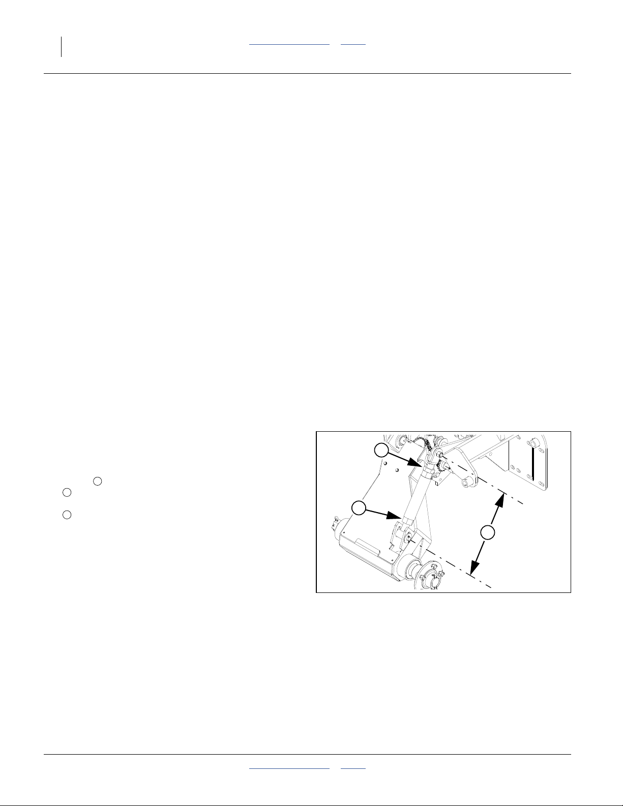
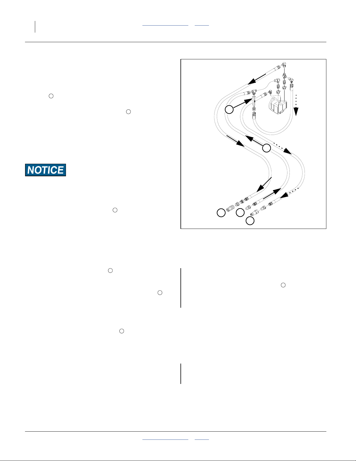
Fan Circuit Operation See also “Fan and Adjustment” on page 35.
Refer to Figure 13
Three hydraulic hoses serve the fan, and must be properly connected for the fan to operate in the correct
direction , at recommended speeds, and without dam-
1
age. See “Hydraulic Hose Hookup” on page 14.
1. Always connect the case drain line first.
2
5
This line protectsthe outer shaft seal ofthe hydraulic
motor.The casedrain is a small line to the hitch, provisioned with a specialized low-seep flat-face case
drain Quick Disconnect. Pressure spikes during
motor operation, and pressure cycles due to temper-
1
ature change are bled off by the case drain.
Motor Seal Damage Hazard
Do not apply pressure to thecase drain line. Do not changethe
special QD connector. A restricted or sealed case drain line
will promptly result in motor seal damage.
2. Connect the motor return line second, to sump.
The drill includes a 1<numerator>1⁄<denomina-
tor>16in low back-pressure QD coupler set. Install
the receptacle on a tractor sump port, and not at a
normal remote return port. The unusual size aids in
3
3
4
2
Figure 13
Hydraulics at Fan
29781
ensuring correct connection,so that themotor return
line handles high volume at low back-pressure,
ensuring full motor performance.
3. Connect the motor inlet line to a tractor remote
capable of 4.5 gallons/minute. If a priority remote is
available, use it for the fan.
4. The fan hydraulic circuit includes a check valve ,
which provides a relief path for oil at motor shutoff.
If the fan is connected in reverse, flow through this
4
If the fan is connected in reverse, it may not run at all
(due to no oil source at the return connection). If oil is
present, oil bypass at the check valve prevents the
5
fan from reaching high rpm. A reversed fan may send
5
some airto themeters, but is incapable of providing reliable air flow for planting.
valve results in low fan rpm provides strong indication reversed connection.
Correct fan directionis shown at . If reversed fan is
1
suspected, observeit during shutoff, as the direction
of motion iseasier to see at lower rpms as it slows to
a stop (initial startup is virtually instantaneous, making observation at start difficult).
Fan speed is controlled by the tractor circuit and butterfly
valve (and not the seed monitor).
You may stop the fan by setting the circuit to neutral or
Fan speed can change as oil heats to operating temperature. Re-check meter pressure more oftenduring early
operations.
float. The check valve slows the blades to a stop by
locally recirculating the oil.
118-999M Table of Contents Index 2013-06-04
Page 29
Great Plains Manufacturing, Inc. Table of Contents Index Operating Instructions 25
l
r
f
r
d
d
Fan General Operating Information
Adjust the fan to provide the meter pressure recommended for the seed disk, seed, and seed density. See
the tables and charts for recommended values in the
Seed Rate Manual.
Normal gauge readings are in the 0.8in to 4.0in water
pressure range, and vary considerably with crop.
Refer to Figure 14
Use tractor remote hydraulic valve flow control to set fan
speed and butterfly valve adjustment to make fineadjustments tometer pressure. Precise technique depends on
tractor capabilities:
• The objective isobtain recommended meter pressure,
and maintain it during end-of-pass marker fold,lift and
turn.
• For any setup adjustment, operate the tractor engine
at typical field rpms, and not at idle.
• Preset the butterfly valve:
If the tractor has fine control of remote flow rates, and
consistent flow at varying tractor engine rpm, initially
set the butterfly valve to 30° or less.
If the tractorhas onlycoarse controlof flow,initially set
the butterfly valve to 45°.
• Set the fan circuit flow to bring the gauge reading to
near the recommended value.
• Fine tune the meter pressure with the butterfly valve.
• If the tractor has marginal flow available, or the list circuit has priority, you may need to experiment with
combinations of fan flow and butterfly valve settings.
Always start the fan with a low flow setting.
Gradually bring fan up to the recommended initial meter
pressure.
At excessive rpm, too much air flow can cause:
• oil heating
• slow lift times
If desired pressure cannot be reached, or require unusually high oil flow at low butterfly valve settings, chances
are the fan is running backwards. Reverse the
inlet/return lines at the hitch.
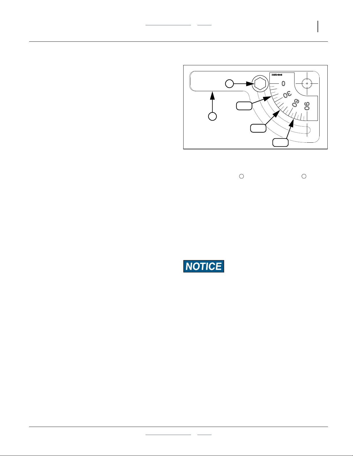
Butterfly Valve Operation:
To adjust, loosen bolt and rotate the handle .
Re-tighten bolt.
0° is wide open - maximum air flow.
90° is closed - minimum air flow.
The valve provides the most effect at settings between
20° and 70°.
Starting at 30° reduces the fan workload.
Starting at45° provides themost adjustment rangeup or
down.
Low Population Risk at Turns:
The fan requires up to 4.5 gpm. This figure does not include oi
for lift/lower or oil for marker operation. Aggressive lift/lowe
operations, and simultaneous lift/marker operations, can
reduce fan rpm below that needed to pressurize meter disks. I
seed falls out of pockets, low population bands will occu
shortly after turns.
Unless the tractor has generous oil flow capacity, raise/fol
markers before lift, and lift slowly. Watch meter pressure an
tune operations to keep it at planting levels in turns.
1
20°
2
45°
Figure 14
Fan Butterfly Valve Handle
1 2
70°
25137
2013-06-04 Table of Contents Index 118-999M
Page 30
26 2025A/2525A Table of Contents Index Great Plains Manufacturing, Inc.
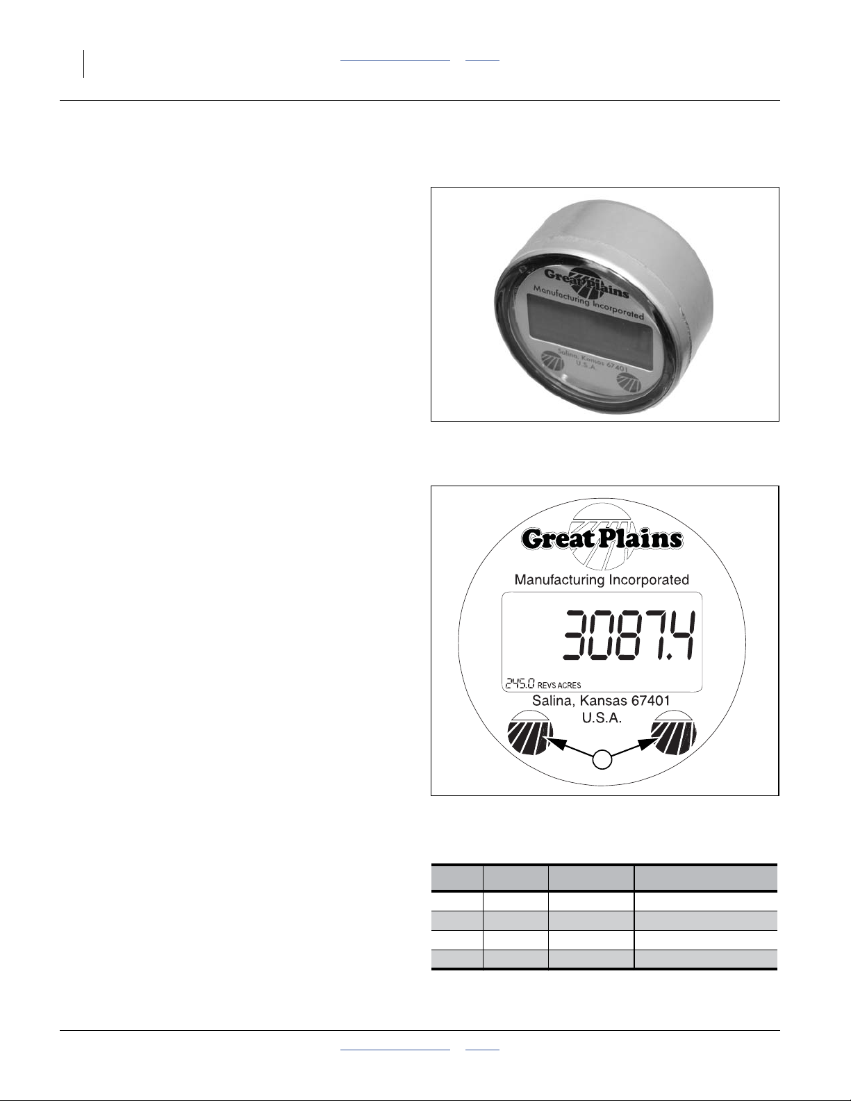
Acremeter Operation
Refer to Figure 15
The acremeter counts shaft rotations whenever the shaft
is rotating - this is with the drill lowered and in motion or
during crank operation. The meter is programmed to display rotations as acres or hectares, when using all rows,
factory-specified tires and tire inflations.
Note: Unusual conditions and/or non-standard row
spacings can cause the acremeter tally to vary
from actual acres planted.
Normal Operating Sequence
1. Record the acremeter reading atthe start of planting
(and after calibration). The large “12345.6” format
display is the grand total area planted since meter
installation. If the display is blank, see “Dormant Display” below.
2. Lower drill and plant. Acremeter counts shaft rotations, calculates acres or hectares, and adds to the
running grand total.
3. During planting (drill lowered and moving forward),
the display blanks (goes dormant), but areatally continues.
4. When raised for turns, obstructions and transport,
the drive wheel stops, and the meter counts no additional (non-planting) rotations.
5. Whenever shaft rotation stops, the LCD display activates after 30 to 60 seconds,and remains visible for
30 to 45 minutes.
6. At the completion ofplanting, record the finalreading
or the grand total. Ifthe display goes dormant before
you can read it, see “Dormant Display”.
7. Subtract the reading at Step 1 from the reading at
Step 6 for the total planted in the present session.
Figure 15
Electronic Acremeter
27378
Dormant Display
Refer to Figure 16
To conserve power, the LCDdisplay blanks itself most of
the time. If you need to read the display after it has
“timed out” and gone dormant:
• use the left gauge wheel to turn the meter shaft once,
or
• gently tap or wave a magnet at either of the Great
Plains logo spotson thelower region of thedisplay. Be
careful not to scratch the window.
When active the lowerleft corner displays the revolutions
per area for which the meter is factory-programmed.
118-999M Table of Contents Index 2013-06-04
Acremeter Programming
Drill Units
2025A Acres 891-087C 316.2 REVS/ACRE
2025A Hectare 891-088C 781.3 REVS/HA
2525A Acres 891-101C 245.0 REVS/ACRE
2525A Hectare 891-102C 605.4 REVS/HA
891-101C Meter Display
1
Figure 16
Part No. Program
29827
Page 31

Great Plains Manufacturing, Inc. Table of Contents Index Operating Instructions 27
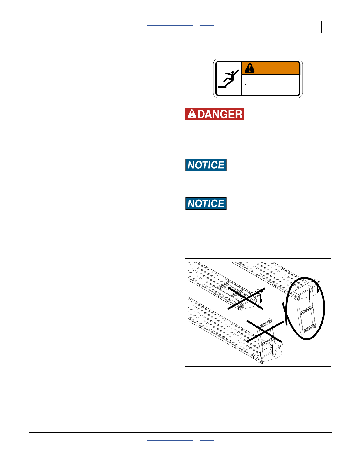
Ladder Operation
WARNING
Falling Hazard:
Lower drill before using ladders andwalkboards. Facetoward
ladder when ascending or descending. Use hand holds provided. Watch your step. A fall from the walkboard could result
in serious injury or death.
Refer to Figure 17
The ladders at each end of the walkboard have three
positions:
1. Locked up for storage:
To put the ladder in this position, swing to the fully
inverted vertical position,and letthe boltsslide tothe
bottom of the slot. Use this position to discourage
climbers when the drill is parked or in storage. This
position is not ideal when the drill is in motion.
2. Folded for transport and field operation:
Use this position when the drill is in motion, as it minimizes stress and wear on the slotted ladder mounts.
3. Down for materials and maintenance:
Use this position for loading seed, unloading seed,
and drill maintenance. Do not use this position during transport, as it reduces lateral clearance. Do not
store the drill with ladders down.
2
3-Point Walkboard Ladder
To avoid serious injury or death:
Watch your step when climbing ladder or
walking on walkboard.
1
Figure 17
838-102C
3
28828
Monitor Operation (Option)
Monitor operation is described in a separatemanual supplied with the DICKEY-john® Seed Manager SE system.
Operations covered in that manual (and therefore not in
this manual) include:
• population monitoring
• setting rate limits and detecting out-of-limits
• GPS integration
Figure 18
Seed Monitor Console
28341
2013-06-04 Table of Contents Index 118-999M
Page 32

28 2025A/2525A Table of Contents Index Great Plains Manufacturing, Inc.
Marker Operation (Option)
Optional marker attachments are available from your
Great Plains dealer.
The operating procedure is different, depending on
whether dual-circuit independent markers or single-circuit sequenced markers are installed.
When fully extended or foldedduring operationsor transport, leave circuit control in Neutral. Set circuit to Float
only for unhitching.
Before operating markers, make sure hydraulics are
properly bled as described under “Bleeding Marker
Hydraulics” on page 76,and markers are operating at a
safe speed, per “Marker Speed Adjustment” on
page 98.
This section presumes correct marker length for your
pass spacing. If this has not been set, or needs to be
changed, see “Marker Extension” on page 100.
This section presumes correctmarker chainslack. Ifyour
chain has been replaced, repaired or stretched, adjust
the links to the correct slack length. see “Marker Chain
Adjustment” on page 99.
Independent Marker Operation
Each marker is on a dedicated tractor hydraulic circuit.
Either or both may be extended or retracted independently by operating the circuit for that marker.
Single-Circuit Sequenced Marker Operation
Dual markers equipped with a sequence valve are powered by the same hydraulic circuit. Starting with both
markers folded, the folding sequence is:
Activate lever - Right unfolds; left stays folded.
Reverse lever - Right folds; left stays folded.
Activate lever - Left unfolds; right stays folded.
Reverse lever - Left folds up; right stays folded.
Sequence repeats.
Both Sides Unfolded (with Sequence Valve)
With both markers in their cradles:
Unfold either side, and when completely deployedMove lever/switch to Retract momentarily, and return to
Extend to deploy other side.
Electrocution Hazard:
Beware of overhead electrical lines. If the markers contact
lines, the tractor, raised drill and any cart can become “hot”
with no indication. A person standing on the ground and
touching equipment can complete the circuit. Serious injuryor
death is likely. At higher voltages electrocution can occur
without direct contact.
Overhead Crushing and Sharp Object Hazard:
Do not allow anyone to stand near or beyond the end of the
wings during marker operations. Marker arms are heavy and
marker discs may be sharp. Serious injury or death is possible.
Equipment Damage / Low Population Risks:
Folding markers at high speed can damage markers, and
starve seed meters of pressurization air. Refer to “Marker
Speed Adjustment” on page 98, and adjust folding speed to a
safe rate.
Note: If one or both markers are extended, they may
drag or shove if left extended during drill raise or
lower operations. To avoid this, fold markers prior
to raise or lower.
118-999M Table of Contents Index 2013-06-04
Page 33

Great Plains Manufacturing, Inc. Table of Contents Index Operating Instructions 29
Field Set-Up Checklists
Use the following tables to develop a final checklist for
your tractor/drill configuration. Additional or fewer steps
may be necessary depending on tractor features, drill
options and planting accessories.
Mechanical Checklist Page
Tool bar height set with 3-point 16
Drill level front to back 16
Ground drive sprockets set for seed disk,
rate, and set alike on each section.
Check chain tension. Re-connect any
loose idler tensioning springs.
33
-
Rotate gauge wheels (top forward), checking that drive system, and meters are
working smoothly.
Record acremeter reading.
Marker extension set 100
Marker disc angle set 34
Electrical Checklist Page
Verify electrical hookups solid 15
Option: Check seed monitor terminal and
observe any diagnostic messages
a
Option: Verify, with drill lowered, that radar
speed sensor is pointed at ground, at an
b
angle approximately 35° below horizontal.
a. Refer to monitor manual.
b. Refer to sensor documentation.
Hydraulic System Checklist Page
Check tractor hydraulic reservoir full Inspect connections for leaks Perform a raise and lower operation Check fan speed and airflow direction a
Check marker circuit 28
a. Operate fan briefly and observe rotor blades spinning toward
exit port. Check rpm on seed monitor.
Air System Checklist Page
Add <numerator>1⁄<denominator>3 cup of
seed lubricant to each air box, prior to first
80
use, and prior to loading seed
Load seed 21
No air leaks (except at meter pockets) -
Row Units Checklist Page
Preset depth handles alike. 43
Preset down force springs alike, except in
tracks.
Set all unit-mounted coulters to1⁄4in shal-
lower than opener blades.
38
41
Check coulter alignment to row 42
Check closing wheel alignment 54
Set press wheels alike. 54
Check action and contact of side depth
wheels
44
Check wheel scraper gaps (if installed) 45
Meters Checklist Page
Correct disks for seed a
Seed inlet shutters set. a
Corn?
Check timing of meters for twin-row
Start fan and bring manifold up to operat-
ing pressure.
Rotate gauge wheels to fill seed disks.
Continue rotation and check for seed flow
below each opener.
a. Refer to Seed Rate Manual.
a
-
2013-06-04 Table of Contents Index 118-999M
Page 34

30 2025A/2525A Table of Contents Index Great Plains Manufacturing, Inc.
Planting
Perform all steps in “Pre-Start Checklist” on page 19
and “Field Set-Up Checklists” on page 29.
First Pass Operation Checklist Page
1. Set tractor 3-point hitch to “depth con-
trol” operation (and not load control)
2. Unfold marker on next-row side. 28
3. Set fan hydraulic circuit to low flow,
engage circuit. Gradually adjust fan
hydraulic flow to obtain recommended
initial meter pressure.
4. Pull forward, lower drill, and begin
planting for a short distance.
5. Stop. Assess:
• planting depth
• seed spacing
• press wheel operation
• fertilizer application (if in use)
6. Make necessary adjustments 32
Sharp Field Turns Checklist Page
-
25
Checking Planting Rate
Although the optional seed monitor can report useful full
pass results, cautious practice includes manually checking the seed rate early in the first pass.
The Seed Rate Chart book for this drill (manual part
number 118-999B) contains sampling instructions.
1. Fold marker 28
2. Raise drill -
3. Make turn -
4. Lower drill -
5. Unfold marker on next-row side. 28
6. Resume planting.
Suspending Planting Checklist Page
1. Stop tractor -
2. Fanhydraulic circuit toFloat or Neutral 24
3. Fold Marker 24
4. Raise drill -
Ending Planting Checklist Page
1. Suspend operations as above, then
2. Unload seed 66
3. Lights ON -
4. Transport 20
118-999M Table of Contents Index 2013-06-04
Page 35

Great Plains Manufacturing, Inc. Table of Contents Index Operating Instructions 31
Short-Term Parking
1. Fold markers. See “Marker Operation (Option)” on
page 28.
2. Choose a location with level firm ground. Do not
unhitch on a slope.
3. Raise the drill.
4. Lower parking stand (page 31).
5. Disconnect hydraulic lines. Secure them so that they
do not touch the ground.
6. Disconnect electrical cables, capping where provisioned.
Long-Term Storage
Complete Parking steps first.
1. Park the drillindoors ifpossible, per the stepsabove.
Great Plains recommends parking/storing in the
raised configuration and on any provided parking
stands.
2. Unload seed from boxes (page 66). Store drill only
without seed.
3. Unload seed from meters (page 66).
4. Remove seed disks from meters (this is primarily to
relieve pressure on brushes). Clean disks of residue
build-up (see Caution at right). Use mild soap,
non-abrasive scrubbers, and hot or warm water. If
using sealed storage, dry disks prior to storage.
Possible Chemical Hazard:
Seed disks will have talc and graphite residue, and may have
residues of hazardous seed treatments. Do not wash disks
where food is prepared, or where cookware or dinnerware is
washed. Wear gloves when washing disks. Avoid spray.
Although the disks are dishwasher-safe, do not wash them in
an appliance also used for food cookware or dinnerware.
5. Close seed inlet shutters at meters (to prevent pest
entry to seed hoses). Thoroughly clean seed and
seed treatment residue from seed meters. See
“Meter Clean-Out” on page 66, for more information.
6. Lubricate all points listed in Maintenance to prevent
rust.
7. Clean drill of mud, dirt, excess oil and grease.
8. Inspect for worn or damaged parts. Make repairs
and service during off season.
9. Use spray paint to cover scratches, chips, and worn
areas on the drill to protect the metal.
10. Cover drill with a tarp if stored outside.
2013-06-04 Table of Contents Index 118-999M
Page 36

32 2025A/2525A Table of Contents Index Great Plains Manufacturing, Inc.
Adjustments
To get full performance from your 3-Point drill, you need
an understanding of allcomponent operations, andmany
provide adjustments for optimal field results. Some of
these have been covered earlier in this manual.
Even if your planting conditions rarely change, some of
these items need periodic adjustment due to normal
wear.
Adjustment Page The Adjustment Affects
Frame height 21 Planting depth consistency
Frame level 16 Planting consistency
Manifold Pressure (values from SRMa) 35 Consistent seed flow and disk singulation
Planting Rate SRMaRefer to Seed Rate Manual
Marker Adjustments
Marker Extension 100 Intended swath spacing
Marker Chain Length Adjustment 54 Marker folding operation
Dual Marker Speed Adjustment 98 Reliable marker operation
25AP Row Unit Adjustments
Opener Depth 43 Planting depth
Row Unit Down Pressure 38 Planting depth uniformity
Row Unit Lock-Up 51 Single/twin-row operation
Row Cleaner Adjustments (Option) 40 Row preparation
Coulter Adjustments (Option) 41 Seed depth uniformity
Opener Disk Adjustments 43 Seed depth, seed-to-soil contact
Side Depth Wheels 43 Seed depth, prevents plugging
Adjusting Gauge Wheel Scrapers 45 Consistent seed furrow depth
Seed Meter Setup and Adjustment 46 Consistent seed population
Seed Inlet Shutter 46 Seed flow to meter; seed pool slope
Seed Pool Slopes 47 Minimal skips and doubles
Seed Disk Installation 48 Correct seeding of your crop and population
Row Shut-Off 49 Alternate row spacings
Seed Firmer Adjustments (Option) 52 Seed-soil contact
Press Wheel Adjustment 54 Effective soil coverage
Speed Sensor Gap (Option) 97
a. SRM: Seed Rate Manual (118-999B)
118-999M Table of Contents Index 2013-06-04
Page 37

Great Plains Manufacturing, Inc. Table of Contents Index Adjustments 33
Setting Planting Rate
Full detailson ratesetting sprocket selection and installation are found inthe Seed RateManual (pub. number
118-999B). This is a summary. Adjusting the seeding
rate requires the following:
1. installing seed disks compatible with the crop and
field speed for the intended population,
2. adjusting drive speed Range sprockets,
3. adjusting Transmission sprockets,
4. setting seed inlet shutters and meter pressure,
5. checking seeding rate.
Seed Disk Selection and Installation
See the Seed Rate Manual for seed disk selection. In
this manual, see “Air-Pro® MeterDisk Installation”on
page 48. Before setting the seeding rate, rotate the
gauge wheels. Check that seedmeters, seed tubesand
drives are working properly and free from foreign material.
Range and Transmission
Refer to Figure 19
Set the same Range and Transmission sprocket combinations on both gauge wheel assemblies. Select the
correct DRIVING/DRIVEN pairing from the storage
shafts on the gauge wheel assembly. Driven Transmission shaft is also one of the sprocket storage shafts.
Each gauge wheel drives its half of the drill. If a chain
breaks or is removed, that half of the drill does not plant.
Drive Speed Range Sprockets
Range sprockets are at front left on each gauge wheel
assembly. Determine the correct drive speed Range
sprockets for your seed by referring to the Seed Rate
Manual.
Transmission Sprockets
The Transmission sprockets are at top right on each
gauge wheel assembly. Determine the correct drive
speed Transmission sprockets for your seed by referring
to the Seed Rate Manual.
Shutters and Manifold Pressure
Obtaining a consistent seed rate, with minimum skips
and doubles, requires adjusting the meter seed inlet
shutter opening, and operating the air system at the a
TRANSMISSION
DRIVING
DRIVING
Figure 19
DRIVEN
DRIVEN
RANGE
26218
Drive Sprockets
pressure most likely to hold one, and only one, seed per
pocket in the seed disk.
The Seed Rate Manual provides suggested initial settings for both shutter and pressure. See page 46 for
shutter adjustments. See page 35 for pressure adjustments.
Checking Planting Rate
Without an optional seed monitor, it is crucial to perform
an actual furrow checkearlyin theplanting toassure that
you are obtaining the desired rate. Periodic inspection of
meters, and further furrow checks, ensurethat rate is not
upset by seed run-out, blockages and malfunctions.
The optional seed monitor senses seed passage below
the meter. It accurately counts individual larger seeds,
and functions as a blockage monitor for smaller seeds.
However, afurrow check isstill wise, as setup errors and
speed mis-calibration can cause the monitor to report a
false rate.
2013-06-04 Table of Contents Index 118-999M
Page 38

34 2025A/2525A Table of Contents Index Great Plains Manufacturing, Inc.
Marker Adjustments
There are three adjustments and three setup/maintenance items for markers:
• Disk Angle (following)
Even if your row spacing rarely changes, you may
need to adjust disk angle for soil conditions and planting speed.
• Shear Bolt Replacement (page 75)
If a marker hangs up on an obstruction, a bolt at the
fold is designed to fail.
• Marker Cylinder Bleed (page 76)
Once set for a specific row spacing, this only needs
periodic checking to ensure the clamp is secure.
• Marker Chain Length (page 99)
• Marker Extension (page 100)
Once set for a specific row spacing, this only needs
periodic checking to ensure the clamp is secure.
• Marker Speed (page 98)
Once initially set by your dealer, this rarely needs
modification.
You may be injured if hit by a folding or unfolding marker.
Markers may fall quickly and unexpectedly if the hydraulics
fail. Never allow anyone near the drill when folding or unfolding the markers.
Marker Disk Adjustment
Sharp Object Hazard:
Use caution when making adjustments in this area. Marker
disks may be sharp.
Refer to Figure 20
1. To change angle of cut, and the width of the mark,
loosen1⁄2-inch bolts holding the disk assembly.
For a wider mark , increase the angle of the
marker with respect to the tube . For a narrower
N
mark , reduce the angle.
Note: Do not set a marker angle wider than need to
make a useful mark. Excess angle increaseswear
on all marker components.
2. Tighten bolts .
Note: The direction of travel tends to drive the disk
angle to Wide. If bolts are not tight enough, or
loosen over time, the disk will slip into the Wide
mark configuration.
2
2
W
1
T
W
N
2
Figure 20
Marker Disk Angle
1
T
T
11757
118-999M Table of Contents Index 2013-06-04
Page 39

Great Plains Manufacturing, Inc. Table of Contents Index Adjustments 35
Fan and Adjustment
1. These steps presume that correct seed disks are
installed (per SeedRate Manual),and the seedinlet
shutters are set for the seed (page 46).
2. With fan off, check meter pressure reported by the
Magnehelic®
3. Determine the recommended meter pressure based
on your own notes or the published value in the
Seed Rate Manual.
4. Put tractor in Park and set brakes. Set tractor engine
speed to typical field rpm. Lift drill.
5. Start thefan. Gradually increase fan speed usingthe
tractor’s hydraulic flow control for the circuit. Using
hydraulicflow and/or the butterfly valve, adjust meter
pressure to the developed or suggested value from
step 3.
6. Rotate gauge wheels to fill meters. Meters are filled
when seed begins emerging below two or more
openers. With fan running,put thetractor inPark and
set the brakes. Walk behind the wings, remove several rain covers, and check for seed in meters by
looking through the clear disks.
Note: Meter fill must be done separately for each drill
section.
7. Re-check meter pressure. With meters and disks
filled, air lossthrough emptydisk pockets is reduced,
and meter pressurization can change.
8. Begin planting. Troubleshoot any obvious problems
or optional seed monitor alarms.
9. During the first pass, take note of the average populations reported on the optional seed monitor.
If no seed monitor is installed, or the reported seed
monitor population varies from your intentions by a
significant amount, it is imperative to perform a furrow check.
For serious rate variances, for which the source of
the problem and the solution are not quickly determined, see “Population Troubleshooting Charts”
on page 58.
If the population is only slightly low, the problem can
be skips (periodic empty disk pockets). If slightly
high, the problem can be doubles (period pockets
with double seed). An adjustment to the meter pressurization may correct either condition (see step 12).
a
gauge. Re-zero as needed.
1
Magnehelic® Gauge
Re-zero the Magnehelic® gauge on level ground with
the fan off, and if possible, under no-wind conditions.
Turn the set screw on the meter face until it reads
zero from the tractor driver’s viewing position.
Port ID for Troubleshooting:
Over-pressure relief port (with plug in place)
2
Low-pressure port (breather/atmospheric pressure)
3
High-pressure port (from manifold chamber)
4
Small seeds, such as Milo, may be under-reported by
the optional seed monitor. Use the “Alternate
Skip/Double Check” below to verify seed status at the
disc pockets.
Furrow Check:
Expose several seeds in each of several rows, being
careful not to disturb their relative positions. Measure
and average the distancebetween seeds.Compare this
to the predicted seed spacing for the population in the
Seed Rate Manual.
Any instances of no seed where expected may be a
sign of “skips”. Finding two seeds at the same spot is
clear indication of “doubles”
1
2
Figure 21
3
4
29842
a. Magnehelic is a registered trademark of Dwyer Instruments, Inc.
2013-06-04 Table of Contents Index 118-999M
Page 40

36 2025A/2525A Table of Contents Index Great Plains Manufacturing, Inc.
10. Resume planting.
A small varyingpopulation deviation betweenrows is
normal. If a row is consistently running lower or
higher than the other rows, it could indicate a meter
or seed sensor problem that needs attention. “Popu-
lation Troubleshooting Charts” on page 58.
11. Continue to monitor meter pressure.
When oil reaches operating temperature, fan speed
can change. Expect to make periodicadjustments to
fan circuit or butterfly valve to maintain ideal meter
pressure.
12. Skips:
If all else is correct, and the overall average population is running low (or there are gaps upon furrow
check), the cause may be seeds falling out of disk
pockets before delivery to the seed tube. Increase
meter pressure to correct this.
13. Doubles:
If all else is correct, and the overall average population is running high (or there are double seeds upon
furrow check), the cause may be two seeds in some
disk pockets at delivery to the seed tube. Decrease
meter pressure to correct this.
Insufficient meter pressure, or unusually rough fields,
can increase theincidence of emptypockets.Be sure to
rule out other causes (such as skipping chains, meter
starvation, incorrect meterdisks) beforeadjusting meter
pressurization to reduce apparent skips.
Excess meter pressure can increase the incidence of
doubles. Be sure to rule out other causes (such as
incorrect meter disks) before adjusting meter pressurization to reduce doubles.
Fine-Tuning (with optional Seed Monitor)
After several passes, and you are comfortable with the
drill’s operation, you can optimize meter pressurization.
Use this method during longer passes, so there are
fewer distractions (and see sidebar regarding Milo).
14. Observe the current overall average population
reported by the monitor.
15. Adjust the fan speed down, in small steps, waiting
5-10 seconds between adjustments, until skipsoccur
(actual population begins falling below target). Note
the pressure at which skips begin.
16. Restore pressure to the initial value at step 14.
17. Adjust the fan speed up, by periodic small increments, until doubles occur (actual population begins
rising above target). Note the pressure at which doubles begin.
18. Adjust meter pressure to a value halfway between
the limits established at step 15 and step 17. This is
the ideal value for your crop, disk and population,
providing equal margin against skips and doubles.
Record this value for future use.
Alternate Skip/Double Check
Small seeds, particularlyMilo, are lessreliably sensed as
skips or doublesby the seedtube sensors, andwatching
monitor population is unlikely to locate the pressure limits. This test can also be quicker for all seeds.
A. After planting a few passes with initial settings,
remove the rain covers from several rows (use rows
with a variety of seed hose lengths and routes).
B. Make a meter pressurization adjustment. Resume
planting for a pass or less.
C. Stop drill motion but leave engine at field rpm and
fan running.
D. Inspect the seed disks closely. Look for empty seed
cells (skips) and cells with multiple seeds (doubles).
E. Repeat step B-to-step D until limits are established.
Record limits. Re-install rain covers. Plant with
median settings.
118-999M Table of Contents Index 2013-06-04
Page 41

Great Plains Manufacturing, Inc. Table of Contents Index Adjustments 37
l
25AP Series Row Unit Adjustments
Refer to Figure 22 (which depicts a row unit populated
with most optional accessories supported for use with
the 3-Point drill)
Fromfront toback, aGreat Plains25 SeriesAir-Pro®row
unit (25AP) can include the following capabilities (some
optional):
1. Lock-Up Pin Storage Hole (Hole Standard)
See “Row Unit Shut-Off” on page 49.
2. Down-Pressure Cam (Standard)
Row units are mounted on parallel arms. This parallel-action mounting allows the row-unit to move up
and down while staying horizontal. Springs add an
adjustable force, set by the cam, to the row weight.
See “Row Unit Down Pressure” on page 38.
3. Air Inlet (Standard)
Pressure-regulated air enters the meter here and
holds seed in the disk pockets. See “Fan and
Adjustment” on page 35.
4. Seed Delivery Inlet (Standard)
Gravity carries seed from the seed box into the
meter at the shutter . The tube is easily removed
for inspection. There are no adjustments.
6
2
1
3
4
5
8
6
9
7
14
10
Do not back up with row units in the ground. To do so wil
cause severe damage and row unit plugging.
12
11
25AP Series Row Unit
13
Figure 22
15
16
29600
5. Air-Pro® Seed Meter (Standard, Choice of Disks)
See “Air-Pro® Meter Disk Installation” on page 48.
6. Seed Inlet Shutter (Standard)
This controls the level of bulk seed at the disk.There
are four operating settings, plus fully open
(clean-out) and fullyclosed (shut-offor storage).See
“Seed Inlet Shutter Adjustment” on page 46.
7. Side Gauge Wheel Depth (Standard)
The T-handle sets planting depth by controlling the
height of the side gauge wheels relative to the
opener discs. See “Side Gauge Wheel Adjust-
ment” on page 44.
8. Press Wheel Force, Angle, Stagger (Standard)
The press wheels close the furrow, gently pressing
the soil over the seed to ensure good seed to soil
contact for even emergence. See “Press Wheel
Adjustment” on page 54.
9. Row Unit Lock-Up Hole (Hole Standard)
Pins are standardon somemodels. Withthe rowunit
raised above level, the lock-up pin is inserted here.
See “Row Unit Shut-Off” on page 49.
10. Row Cleaner (Option)
Row cleaners cleartrash fromthe row, to adepth set
by an adjustment on the arms. See “Unit-Mount
Cleaner Adjustments” on page 40.
11. Unit-Mount Coulter (Option)
Coulters cut remaining trash and begin opening the
seed furrow.Working depthis setby row depthand a
mounting hole selection. See “Coulter Adjust-
ments” on page 41.
12. Opener Discs (Standard)
Row-unit double disc openers create the seedbed
furrow. They have adjustments for angle and spacing. See “Row-Unit Opener Disk Adjustments” on
page 43.
13. Seed Tube with Sensor (Standard)
Requires no adjustment.
14. Scrapers (Optional, not shown)
Inside scrapers require no adjustment. For gauge
wheel scrapers, see “Adjusting Gauge Wheel
Scrapers” on page 45.
15. Seed Firmers (Seed Flap Standard, not shown)
An optional seed firmer (Keeton shown) minimizes
seed bounce and improves soil contact. It may also
deliver fertilizer. See “Seed Firmer Adjustments”
on page 52.
16. Press Wheel Type (Choice)
A variety of single and dual press wheel assemblies
are available, some region-specific. Consult your
Great Plains dealer.
2013-06-04 Table of Contents Index 118-999M
Page 42

38 2025A/2525A Table of Contents Index Great Plains Manufacturing, Inc.
Row Unit Down Pressure
Refer to Figure 23
The ideal amount of down-force causes the side gauge
wheels to compress any loosesurface soil, butnot press
a trench into subsoil.
To assess down-force, operate the planter for a short distance on typical ground (with or without seeding), and
stop. Leave the planter lowered (row units in ground).
At several row units, inspect the furrow created by the
opener discs, but prior to furrow closing by the press
wheels.
Note: Be sure to inspect rows both in and out of tire
tracks.
Refer to Figure 24
1. If the side gauge wheels are leaving no tracks, or
light tracks, increase down-force.
2. If the wheels are compressing trash and loose soil,
and leaving clear tracks right at the top of the subsoil, down-force is probably correct and needs no
adjustment.
3. If the wheels are creating a trench into the subsoil,
down-force is too high and needs to be reduced.
Figure 23
Checking Furrow
Light or no side gauge
wheel tracks
Gauge wheels compress
loose soil only
Inspect Furrow Here
Insufficient down-force
Increase down-force
1
Ideal
No adjustment required
2
{
29600
Adjusting Down-Force
Refer to Figure 25
Row unit springs provide the primary down pressure
necessary for row unit disks to open a seed trench. The
weight of the row units themselves contributes about
130 pounds (59 kg) of the total force.
The springs allow therow units to float down into depressions and up over obstructions. Springs also provide
down force on coulters whenusing optional row mounted
coulters, and provide the primary down force on row
cleaners (optional), seed firmers (optional) and press
wheels.
1
Side gauge wheels
making deep tracks
Assessing Down-force
1
25 Series Row Unit Springs
Down-force too high
Reduce down-force
3
Figure 24
Figure 25
29600
118-999M Table of Contents Index 2013-06-04
Page 43

Great Plains Manufacturing, Inc. Table of Contents Index Adjustments 39
An adjuster cam sets down pressure individually for
2
each row unit. This isuseful for penetrating hard soiland
planting in tire tracks. For best results always adjust tractor tires so they are not ahead of 30in rows.
Refer to Figure 27 and Figure 28
Cam Notch Pounds Kilograms
zero (out of notch) Lock-Up & Maintenance
one 235 105
two 260 120
three 295 135
four 355 160
five 415 190
six 475 215
tip Do Not Use
29831
Use only enough down pressure to cut the seed trench
and maintain proper soil-firming over seed. Excessive
row unit down force will lead to premature wear on row
unit components, uneven seed depth and gauge wheel
slippage.
Refer to Figure 26 (shown at cam setting 2),
Figure 27 and Figure 28
To adjust down pressure, use a 1<numerator>1⁄<denominator>8in (29mm) openend wrench orthe tool stored
3
under the walkboard.
1. Raise the drill. Although this adjustment can be
made with the planter lowered, the springs will be in
tension, and will require more effort. The extra force
required may also damage tools.
2. Put tractor in Park and shut it off.
3. Position wrench on the fixed nut near or slightly
4
forward of vertical.
4. Pull upper spring link back.
5. Move the adjustment cam to the new setting on
the spring adjust bar .
5
2
6
Note: Do not set all rows higher than notch four. Using
high settings across all rows causes uneven planting, and may cause gauge wheels to slip or lose
traction entirely. Individual rowsmay be set higher
if running in tire tracks.
3
Figure 26
25AP Series Row Unit
Spring Adjustment
4
6
Figure 27
Row Unit Minimum Cam (at 1)
Figure 28
Row Unit Maximum Cam (at 6)
2
5
29605
27065
bottom
27065
top
2013-06-04 Table of Contents Index 118-999M
Page 44

40 2025A/2525A Table of Contents Index Great Plains Manufacturing, Inc.
Unit-Mount Cleaner Adjustments
Refer to Figure 29 and Figure 30
Optional Martin row cleaners are unit-mounted, using:
UMRC: Unit-Mount Row Cleaner (stand-alone), or
UMC-RC: Unit-Mount Coulter RC (on coulter bracket,
with or without a coulter disk present).
There are two adjustments:
1. Wheel placement (forward or aft mounting hole, for
more or less aggressive cleaning), and
2. Wheel height, adjusted by a stop. Cleaner arms
float. The stop only sets the lowest position.
In UMRC mount, a pinned cross-tube on the mount
3
adjusts the depth. In UMC-RC (coulter) mount, a sliding
down-stop block adjusts how close to the ground the
6
row cleaners operate.
The row cleaner needs to be adjusted for your condi-
tions, crop changes, and as coulters and openers wear.
Ideally, cleaners contact only the trash, and do not disturb the soil. If allowed to “dig”, row cleaners can reduce
seed coverage.
Suggested initial depth is tine tips at ground level.
Make the adjustment withthe drill raised.Install lift-assist
cylinder locks. Also check bolt tightness prior to each
5
planting session, to avoid down-stop slippage.
To adjust the row cleaner:
1. Determine the height adjustment required. Measure
from the lowest tine to the ground. Determine the
desired new measurement.
2. Support most or all of the weight of the arm to prevent injury and ease theadjustment. Loosen bolts
on UMC-RC. Remove bent pin on UMRC.
2
3. Support arm at desired height.
4. UMRC: Slide adjustment tube until cross-tube
contacts arm at target height. Insert bent pin in
1 3
2
whichever hole pair is most in alignment.
5. UMC-RC: Slide the down-stop on the arm :
6 4
- back toward the pivot for shallower cleaning, or
- forward toward the tines for deeper cleaning.
Tighten the bolts . Each possible hole pairing
5
adjusts the tine height by about <numerator>3⁄<denominator>4in (19mm).
6. Check the new height measurement.
Refer to Row Cleaner manual 204-085M-A for further
information on use, adjustment and maintenance of row
cleaners.
UMRC: Cleaner Adjust
Sharp Object Hazard:
Wear hand protection when working in this area. Row cleaner
tines, casting edges and coulter blades are sharp.
5
UMC-RC: Row Cleaner Adjust
1
2
Figure 29
5
Figure 30
3
27308
4
6
27343
118-999M Table of Contents Index 2013-06-04
Page 45

Great Plains Manufacturing, Inc. Table of Contents Index Adjustments 41
Coulter Adjustments
Note: Coulters are not factory-installed. Check align-
ment and depth prior to first use.
Coulter Depth Adjustment
The ideal operating depth for coulters is1⁄4in (6mm)
above opener depth. Although they may have originally
been set to this depth, coulter (and opener) blades wear
with time, and may need adjusting.
Adjusting the coulter depth is accomplished by re-mounting the coulter blade in one of the six mounting holes
arranged in a staggered pattern in the coulter bracket.
Refer to Figure 31 and Figure 32
Raise planter andinstall cylinderlocks before working on
coulters. Row unit may be fully lowered or locked up. Do
not attempt to move blade when the current or new position causes it to contact the ground during the adjustment. Be careful around the front end of row units. Row
cleaner tines and coulter blades may be sharp.
To adjust coulter depth:
1. Determine the present opener and coulter depths.
2. Note which bracket hole the coulter is presently
using.
3. Determine which new hole will position the coulter
closer to the1⁄4in-above depth. See the table below.
4. Removethe5⁄8-11 x 4inbolt, lock washer and nut(
in Figure 31).
5. Move the blade to the new position. Insert the bolt,
and tighten on the lock washer and nut.
Figure 31
25 Series Unit-Mounted Coulter
2
3
5
1
4
7
6
7
29124
Hole
Number
2
3
5
1
4
6
6. Re-adjust row cleaners, if installed.
If a worn coulter cannot be adjusted to satisfactory operating depth, replace coulter.
2013-06-04 Table of Contents Index 118-999M
Depth of (new) coulter blade
relative to (new) opener blades
1in (25mm) above
5
⁄8in (16mm) above
1
⁄4in (6mm) above
0
<numerator>3⁄<denominator>8in (9.5mm)
below
<numerator>3⁄<denominator>4in (19mm)
below
Figure 32
Coulter Blade Mounting Holes
29125
Page 46

42 2025A/2525A Table of Contents Index Great Plains Manufacturing, Inc.
Coulter Row Alignment
Refer to Figure 33
For unit-mounted coulters, the ideal alignment is for the
blade to open a furrow directly ahead of the opener
discs.
As a check on coarse alignment, sight along the coulter
blade center-line , the gap between the opener
blades , and the centerline between the press
wheels . If they are clearly out of alignment, either the
2
3
1
coulter or the press wheels (or both) may be in need of
adjustment.
The exacting test of correct alignment is field results.
1
Operate the planter on some test ground (no seed
required), and verify that the opener blades are in the
groove opened by the coulter, and that the press wheels
are centered over the furrow. See “Press Wheel Adjust-
2
ment” on page 54 for press wheel alignment.
3
Refer to Figure 34
To adjust coulter alignment, loosen the four bolts that
4
attach its bracket to the row unit. The holes on the row
unit are slotted, side-to-side, and allow the coulter
bracket sideways and rotational adjustment.
Keep the coulter blade vertical while adjusting.
If theblade cannot be broughtinto alignment, check that
the blade spindle itselfis using thesame holelocation on
each side of the bracket.
Figure 33
25 Series Coulter Alignment
4
Figure 34
25 Series Coulter Mount
26125
26126
118-999M Table of Contents Index 2013-06-04
Page 47

Great Plains Manufacturing, Inc. Table of Contents Index Adjustments 43
Row-Unit Opener Disk Adjustments
25AP Series openers have three adjustments:
1. planting/seed depth
2. opener disc to disc clearance
3. gauge wheel/opener disk clearance (page 44)
Setting Planting Depth
Refer to Figure 35
The “T” handle sets planting depth by limitingthe how
1
high the side depth gauge wheels ride relative to the
opener disks. The position of the seed tube itself is fixed
relative to the disks, and is not adjusted.
To adjustseed depth, pull the “T” handle up and back,
1
move it forward or aft, andset it back in adifferent pair of
holes in the scale.
• For shallower planting, move the “T” handle for-
1
ward.
• For deeper planting, move the “T” handle back.
1
Opener Disc Contact Region
Refer to Figure 36
Opener disc angle and stagger is not adjustable, but
disc-to-disc spacing is, and may need attention as discs
experience normal wear. Spacers will need to be reset
when blades are replaced.
The ideal spacing causes the blades to be in contact for
about one inch . If you insert two pieces of paper
4
between the blades, they should slide to within zero
(touching) to 11⁄2in (3.8cm) ofeach other. If zero, the gap
between the blades should not be significantly greater
than the thickness of two sheets of paper.
If the contact region is significantly larger or there is a
large gap, it needsto be adjustedby moving one ormore
spacer washers.
Adjusting Disc Contact
Refer to Figure 36 and Figure 37
1. Raise the planter and install lift cylinder locks.
2. Remove the side gauge wheels on the row unit in
5
need of adjustment.
3. Remove the bolt retaining the opener disc on
6 7
one side. Carefully remove the disc. Do not lose the
hub components and spacer washers , .
8 9
4. To reduce thespacing betweenthe discs(the normal
case), move one spacerwasher from theinside to
the outside of the disc.
9
8
5. Re-assemble and check disk contact.
2
Figure 35
Opener Adjustments
4
Figure 36
Opener Disc Contact Region
8
7
Figure 37
Opener Disc Spacers
6
1
3
29600
5
26127
9
26128
2013-06-04 Table of Contents Index 118-999M
Page 48

44 2025A/2525A Table of Contents Index Great Plains Manufacturing, Inc.
Side Gauge Wheel Adjustment
Refer to Figure 38 and Figure 39
Disc-to-wheel angle and clearance ideally has the wheel
just touching the disk when the wheel is raised to planting depth (is up against the stop set by the “T” handle.
The goal is to have both disksand wheels turn freely,but
keep soil and trash from getting between them.
These two adjustments interact with each other. Changing one requires at least checking the other.
In addition to changing the disk angle due to changing
depth or new field conditions, these two settings may
need attention over time as the disk and wheels wear
from normal use. This adjustment will also need to be
made if any opener components are replaced.
Refer to Figure 39
For 2in (5.1cm) planting depth, adjust side gauge wheel
angle so wheels contact row unit disks at the bottom of
wheel. Check with row units in soil so wheels are held
up.
At the same time, keep side gauge wheels close to
opener disks so openers do not plug with soil or trash.
Note: Wheels should be out far enough so disks and
wheels turn freely.
Refer to Figure 41 on page 45
To adjust side gauge wheels:
1. Raise the planter and install lift cylinder locks.
2. Loosen hex-head bolt . Move wheel and arm out
on O-ring bushing.
3. Loosen pivot bolt Turn hex adjuster so indicator
4
notch is at 5 o’clock to 7 o’clock.
Note: Use this as the starting point for adjustment.
4. Move wheel arm in so side gauge wheel contacts
row unit disk. Tightenhex-head bolt to clamp arm
around bushing and shank.
Refer to Figure 40
5. Check wheel-to-disk contact at 2in (5.2cm) planting
depth. Lift wheel 2in, check contact and release.
When let go, wheel should fall freely.
• If wheel does not contact disk atbottom to area where
blade leaves contact with soil, move hex adjuster until
wheel is angled for proper contact with disk.
1
2 2
1
Side Gauge
Wheel
Side Gauge
Wheel
Opener
Disks
Incorrect
Correct
Figure 38
Disk/Gauge Wheel Alignment
Contact Within this Area
Figure 39
Opener-Gauge Wheel Contact
Figure 40
Checking Wheel/Disc Contact
22531
26129
118-999M Table of Contents Index 2013-06-04
Page 49

Great Plains Manufacturing, Inc. Table of Contents Index Adjustments 45
• If wheel does not fall freely, loosen hex-head bolt
1
and slide wheelarm outjust until wheel and arm move
freely. Retighten hex-head bolt according to grade:
1
⁄2in Grade 5 bolt, 75 ft-lbs (102 N-m).
1
⁄2in Grade 8 bolt, 110 ft-lbs (149 N-m).
1
Note: Use “Torque Values Chart” on page 90 for refer-
ence.
6. Keep turning hex adjuster and moving wheel arm
until the wheel is adjusted properly. When satisfied,
tighten pivot bolt to 110 ft-lbs (149 N-m).
2
Adjusting Gauge Wheel Scrapers
Refer to Figure 42 (depicting a bottomview)
Scrapers are optional, and may be useful in moist or
sticky soils that tendto accumulateon gauge wheelsand
reduce intended planting depth.
To adjust scrapers:
1. Loosen nut .
2. Slide scraper towardgauge wheel until scraper
5
6 8
touches tire.
3. Slide scraper away from wheel leaving a
<numerator>1⁄<denominator>8in (3mm) gap at .
6 8
7
4. Rotate scraper left and right around bolt, making
sure it cannot touch tire if bumped in field. If it can
touch tire, back scraper away from wheel until it cannot.
5. Center scraper angle on bolt until gap is con-
5 7
stant.
6. Tighten nut .
5
1
Starting Point
Disk/Gauge Wheel Adjustment
1
4
4
Figure 41
5
7
8
Figure 42
Gauge Wheel Scraper
2
2
22524
22525
6
25273
2013-06-04 Table of Contents Index 118-999M
Page 50

46 2025A/2525A Table of Contents Index Great Plains Manufacturing, Inc.
Seed Meter Setup and Adjustment
There are adjustments for seedinlet, andchoice ofdisks.
There are no other adjustments, and in particular no
brush adjustments, at the meter.
Meter Rain Cover
The rain cover keeps side winds from unseating seed in
disk pockets. It also keeps precipitation, sunlight and
field debris out of the meters.
Refer to Figure 43
To remove the rain cover, peel the flexible snap latches,
1 2
at top and rear , awayfrom the meter housing. Pivot
the cover forward and down at tab in slot.
When removing a cover, inspect it for damage and missing parts. If a cover does not have both latches, and an
intact edge seal under the latches, the cover is apt to be
lost during transport or field operations.
To replace a latch, temporarily remove the seal near the
latch. Slide the replacement latch onto the cover lugs
from the meter side, then snap the other end down over
the lugs. Re-install the seal.
Seed Inlet Shutter Adjustment
Refer to Figure 44 (showing the shutter at setting 3)
The seed inlet shutter regulates the volume of bulk seed
presented to the seed disk. The operating settings vary
with crop, seed size and treatments.The shutteralso has
settings for row shut-off (completely closed), and
clean-out (wide open).
The Seed Rate Charts include suggested initial shutter
settings. Refine thesesettings basedon experience, and
on inspection of the slope of the seed pool at the bottom
of the seed disk.
The shutter is operated by a handle. Liftthe handle away
from the meter plate. Move the handle to half a setting
higher than thenew setting,then backto thenew setting,
and lower the pawl into that slot.
The table at right is a general summary of shutter settings.
3
2
Setting Setting Typically Used For
Top (0) Closed: Row Shut-Off, Meter Re-Fill
| (1)
|| (2)
||| (3) Corn, round popcorn
|||| (4) Large corn, or heavily treated corn
Bottom (5) Wide Open: Clean-Out
1
Figure 43
Rain Cover Removal
0
|
Figure 44
Seed Inlet Shutter
Small seeds, such asMilo, with littleor
no treatments
Small treated seeds and ediblebeans
(such as Soybeans)
3
29606
II
III
||||
5
29607
118-999M Table of Contents Index 2013-06-04
Page 51

Great Plains Manufacturing, Inc. Table of Contents Index Adjustments 47
Optimal Seed Pool Slopes
The optimal seed slope is one that results in the most
consistent seeding,with minimalskips and doubles. The
column at right has photographs of pool slopes found to
be optimal for representative seeds.
If the suggested initial shutter settings donot seem to be
working for your seed, adjust the shutter to achieve specific reserve slope targets.
Refer to Figure 45
For medium size and smaller seeds that flow easily, the
slope runs from just above the 8:00 (o’clock) position on
the housing wall, forward and down to one or two seeds
deep at the base of the rear strip brush .
Refer to Figure 46 and Figure 47
For medium size and larger, or heavily treated smaller
seeds that flow less easily, the slope runs from at or
slightly above the 8:30 (o’clock) position on the housing
wall, forward and down to 3-6 seeds deep at the base of
the rear strip brush .
In general,the seeds at the base of the strip brush need
to be deep enough thatno air escapes there,and so that
just enough seeds are present to begin populating cells.
Keep the top left/rear end of the pool below the 9:00
o’clock position (meter horizontal center-line).
Meter Re-Fill
Once planting is underway with the seed pools set, it is
infrequently possible for bridging at or above the inlet to
starve the meter of seed.
An empty meter causes a “Row Failure” alarm on the
optional seed monitor. Row numbers are counted from
the left wing (outside row is row 1).
Stop, and put the tractor in Park. Leave the fan running.
Locate the failed row, remove the rain cover, and verify
that the meter is empty. Note the shutter setting. Temporarily open the shutter one of two notches wider. if the
problem was inlet bridging, seed should flow into the
meter immediately.
If inlet bridging is not the problem, little or no seed flows
into the meter with the shutter open wider. In this case,
the problem is further upstream in the seed flow, and
maybe bridging atthe air releasescreen atthe topof the
meter, or plugging in the seed box.
If no obvious foreign object was the cause of the bridging, the shutter setting may have been too small for the
seed. Verify that this and other operating rows were at
the correctinitial shutter setting. If so, re-set the shutters
to the next higher opening.
1
1
Milo: Seed Inlet Shutter at: 1
Soybeans: Seed Inlet Shutter at: 2
Corn: Seed Inlet Shutter at: 3
Foreign Object Risk:
After clearing a bridge, or a delivery blockage above the
meter, check the seed pool at the meter for any debris that
might have been the original cause. Remove such debris from
the meter before planting. Don’t run the risk of an object
lodging in a seed pocket and causing on-going skips.
8:00
Figure 45
8:30
Figure 46
8:30
Figure 47
1
29602
1
29604
1
29603
2013-06-04 Table of Contents Index 118-999M
Page 52

48 2025A/2525A Table of Contents Index Great Plains Manufacturing, Inc.
Air-Pro® Meter Disk Installation
1. Cross-check Seed Rate Chart data against part
number/description molded into disks to be used.
Population Risk:
Use the same disk in all active rows.
2. Inspect disks to be installed. Do not install damaged
or excessively worndisks. Either can cause irregular
seeding. Chips and cracks accelerate brush wear.
3. Remove meter rain cover (page 46).
Refer to Figure 48 (depicting an emptymeter)
4. Inspect meter (see page 68 for details).
5. Make sure clamp is aligned with seat .
Refer to Figure 49
6. With the seed pocket side facing the meter housing,
place the new seed disk on the disk seat.
7. Rotate disk clamp clockwise 45deg to clampdisk.
Clamp seats into detents in disk hub.
Note: On a new meter, or with new brushes installed,
force the disk into the brushes to allow the disk
clamp to rotate. This condition eases asthe brush
fibers are trained during initial rotations.
Note: With slightly used brushes, when a disk is first
clamped, it is normal for the disk hubto be flat with
the face of the disk seat only on the inlet (rear)
side. The disk fully seats as it first turns. This condition eases as the brush fibers receive further
use.
1 2
1
3
4
2
Figure 48
Disk Removed From Meter
3
1
Figure 49
Disk on Clamp and Seat
1
29608
29611
Brush Mis-Seating Risk:
Rotate disks forward shortly after disk installation. If planting
is not anticipated within an hour or two of disk installation,
rotatethe drive system a few turns to ensure that meter brushes
lean in the correct direction. Correct lean improves meter
performance and reduces air consumption. This step is
particularly important for new brushes.
Brush seating may be accomplishedwith orwithout seed
present. Rotate the section’s gauge wheel (top forward),
or rotate the section’s meter drive shaft, top forward, with
a <numerator>7⁄<denominator>8in open-end wrench.
8. Reset seed inlet shutter to setting recommended
by Seed Rate Chart, or toyour own developed value.
9. Re-install rain cover (page 46).
118-999M Table of Contents Index 2013-06-04
4
Figure 50
Disk Clamped
29614
Page 53

Great Plains Manufacturing, Inc. Table of Contents Index Adjustments 49
Removing a Seed Disk
Refer to Figure 51
1. Remove rain cover. If seed is present, close
shutter topreventmore seed from entering meter.
Attach funnel (page 66).
2. Hold seed disk in meter. Rotate disk clamp counterclockwise 45° to release disk.
3. Tilting top of disk toward meter, slowly remove disk,
allowing seed to collect in funnel. Open shutter to
release remaining seed up to wing tube.
4. Clean seed from all brushes. Clean disk seat ( in
Figure 48 page 48), so that new disks can seat fully.
Inspect brushes for excess wear and damage. See
“Meter Brush Maintenance” on page 68.
5. Inspect removed disks forexcess wear and damage.
Set aside any disks requiring replacement. Clean
other removed disks and place in storage. See
“Seed Disk Maintenance” on page 70.
6. Re-install the rain cover (page 46).
4
1
3
4
2
1
Figure 51
Remove Disk
29611
Row Unit Shut-Off
Skip-row operations, such as planting from every other
row when switching from 30in twin-row to 30in single-row, requires shutting down unused rows.
Shutting off seeding at a row involves 4 to 7 steps:
1. Identify the rows to shut off.
2. Install outlet plugs in the seed box.
3. Fully close seed inlet shutter (always done).
4. Replace seed disk with blank disk (always done).
5. Lock up row unit to reduce wear (optional).
6. Reset marker extension (if used, page 100).
7. Reset monitor active row pattern and row spacing to
avoid nuisance alarms (always done).
Note: Meter drive is not disabled on 25AP row units dur-
ing shut-off.
2
1
Figure 52
Seed Inlet Shutter Closed
29609
2013-06-04 Table of Contents Index 118-999M
Page 54

50 2025A/2525A Table of Contents Index Great Plains Manufacturing, Inc.
1. Identify Rows to Shut Off
On twin-row drills, openers are installed with short and
1
long opener mounts. If locking up unused rows of a
twin-row drill, shut off the rear (long mount) rows.
On single-row drills with mid-length mounts, any rows
may be locked up.
2. Close Seed Tube at Box
Refer to Figure 53
To prevent a small amount of seed from becoming
unavailablefor planting, installplugs at thetop of seed
1
tubes at unused rows. See page 83 for plug ordering
information.
Figure 53
26226
Seed Tube Shutoff
3. Close Seed Shutter
Refer to Figure 52 on page 49
Lift the handle away from the plate. Move it to the top
2
position, and release the handle into the notch.
Closing the shutter prevents meter pressure air from
1
leaking into the seed delivery tube (which is usually
empty if a plug is installed in the box), resulting in lower
pressures in adjacent rows, with risk of skips.
The shutter also stops seed flow from a row as soon as
the meter is empty.
4. Install Blank Disk
Refer to Figure 54
Clean out meter. See “Meter Clean-Out” on page 66.
Remove seed disk and install blank disk. See “Air-Pro®
Meter Disk Installation” on page 48.
Figure 54
Shutter Closed, Blank Disk Installed
29610
Blank disks (part number817-841C) are essential in row
shut-off,both tomaintain consistentmeter back-pressure
to meter pressure and to prevent wear on a seed disk.
Blank disks are engineered to simulate a seed disk with
seed in all pockets. Blanks are particularly important on
the rows with sensor lines to the pressure chamber.
Irregular Seeding Risk:
Always use a blank disk in a shut-off row. Operating with no
disk, or with a seed disk but no seed, destabilizesthe regulated
airflow, particularly at rows with pressure sensor lines.
118-999M Table of Contents Index 2013-06-04
Page 55

Great Plains Manufacturing, Inc. Table of Contents Index Adjustments 51
5. Lock-Up Row
Alternate twin-row units (the rear units) can be pinned in
the up position to accommodate single-row spacing.
Refer to Figure 55
The lock-up pins for each front row unit are located in
a storage hole in therow unit mount. To lockup a unit,
1
2
2
1
the unit must be raised, and the pin moved to thelock-up
3
hole in the row unit shank.
4
3
Crushing and Sharp Object Hazards:
Do not attempt to lift a row unit by hand. The weight of the
unit, plus the force of the springs (even at minimum) is too
great (plus, a free hand is needed for pin insertion). Even with
multiple people lifting, hand-lifting is unsafe - there are
numerous sharp edges, and the row unit snaps down violently
if a grip is lost.
Note: If you lose a pin, the replacement part number is
805-033C
1. Raise the drill. Although this adjustment can be
made with the drill lowered, the springs willbe in tension, and will require more effort. The extra force
may also damage tools.
2. Install lift assist cylinder locks. Lower parking stands.
3. Set the down pressure spring cam to zero, per the
instructions on page 39.
4. Raise the row unit high enough that the hole for the
pin is above the lower parallel arm. This can be done
in several ways, including:
a. use a hoist at the rear of the shank
b. use a jack under the shank extension
4
5
Figure 55
25AP Row Unit Lock-Up Pin
3
5
25269
29600
Crushing Hazard:
Use a jack or hoist. Raising a row unit on a block by lowering
the drill is risky. The potential for hydraulic failure creates a
Figure 56
25AP Row Unit Locked Up
29756
safety hazard. Full lowering can damage components.
Refer to Figure 56
5. Remove the pin from the storage hole and insert
and secure it in the lock-up hole .
6. Lower row unit until lock-up pin rests on lower parallel arm.
2013-06-04 Table of Contents Index 118-999M
2
3
Certain Machine Damage:
Do not pin the row unit while it is in the lowered position.
If the pin is inserted below the parallel arm, unit damage
occurs as soon as planting begins.
Page 56

52 2025A/2525A Table of Contents Index Great Plains Manufacturing, Inc.
Sprocket Indexing (Stagger)
28420
If you are planting:
• twin-row crops,
• with seed disks having 24 cells or less,
• at seed interval spacings above 61⁄2inches (16.5cm),
you can synchronize each pair of adjacent meters in a
twin row sothat you achieve the maximum seed-to-seed
spacing between the units of the pair.
Refer to the Seed Rate Manual for details.
Seed Firmer Adjustments
25AP row units include a standard seed flap, and accept
one oftwo optional seed firmers (which maybe included
in your selected opener bundle).
Row unit disk blades may be sharp. Use caution when making
adjustments in this area. To adjust the Keeton Seed Firmer,
lower the planter until the disks of the row units are resting on
the ground.
Keeton Seed Firmer Adjustment
The optional Keeton Seed Firmer is an engineered polymer shape that slides down the seed trench. It traps
seeds as they exit the seed tube and firms them into the
bottom of the “V”.
Refer to Figure 57
The Firmeris provided with a presettension which is recommended for using the first year. The tension screw
can be tightened in subsequent years according to your
needs. Firmers should provide just enough tension to
push seeds to the bottom of the trench.
1
1
Figure 57
Keeton Seed Firmer
28316
118-999M Table of Contents Index 2013-06-04
Page 57

Great Plains Manufacturing, Inc. Table of Contents Index Adjustments 53
Seed-Lok® Seed Firmer Lock-Up
Optional Seed-Lok® firming wheels provide additional
seed-to-soil contact. The wheels are spring loaded and
6
do not require adjusting. In some wet and sticky conditions the wheelsmay accumulate soil. To avoid problems
associated with this, you can lock-up the firmers.
Refer to Figure 58 (which depicts a rowunit with discs, side
depth wheels/arms andpress wheels removed for illustrative
1
purposes - removal is notnecessary for lock/unlock)
To lock up Seed-Lok® wheels:
1. Raise planter. Insert lift assist cylinder locks.
2. Lift Seed-Lok®lock-up handle untillever stop is
1 2
2
3
free to rotate.
3. Rotate lever stop to side/idle position . Release
lock-up handle .
4. Push up on Seed-Lok® wheel until wheel arm
latches up .
1
4
5
To release a locked-up Seed-Lok®:
1. Insert a1⁄4in tool drive tip in the tool hole of the
handle . Alternatively, lift up on the wheel .
1 4
2. Rotate the handle clockwise (handle arm up) until
the Seed-Lok® wheel releases at the latch point
and falls free.
3. While holding the handleup, rotate the raisedportion
of the lever stop under both sides of the handle
2 2
3
4
5
6
Figure 58
5
Seed-Lok® Lock-Up
Note: Engage the lever stop under the handle when
Seed-Lok®is in use. Ifleft disengaged , afurrow
obstruction could cause unintended lock-up.
31543
2
3
at the arm end. Remove the tool.
Seed-Lok® Seed Firmer Lock-Up (old style)
Optional Seed-Lok® firming wheels provide additional
seed-to-soil contact. The wheels are spring loaded and
2
1
do not require adjusting. In some wet and sticky conditions the wheelsmay accumulate soil. To avoid problems
associated with this, you can lock-up the firmers.
Refer to Figure 59
To lock up Seed-Lock wheels:
1. Raise planter.
2. Rotate Seed-Lok® lock-up handle 90 degrees
2
down on top of row unit body.
3. Push up on Seed-Lok® wheel until wheel arm
3
latches up.
3
Figure 59
Seed-Lok® Lock-Up (old style)
2013-06-04 Table of Contents Index 118-999M
22909
Page 58

54 2025A/2525A Table of Contents Index Great Plains Manufacturing, Inc.
Press Wheel Adjustment
The press wheels close the furrow which gently presses
the soil over the seed to ensure good seed-to-soil contact for even emergence.
To provideconsistent seedfirming, the press wheels are
free to move downward from their normal operating position. Thissystem maintains closing/pressing action even
if the row unit arm is lifted when the disks encounter
obstructions.
There are three adjustments available on the press
wheel assembly:
Refer to Figure 60
1. Down pressure (shown at maximum)
2. Wheel stagger (shown staggered)
3. Centering (see Figure 62 on page 55)
Press Wheel Down Pressure
Handle sets down pressure, which may need adjustment for different soil types and field conditions.
• Relax the handle forward (in the direction of travel)for
• Pull the handle back for increased down pressure.
Note: Higher press wheel down pressures reduce the
Press Wheel Stagger
The factory stagger setting has been found optimal for
residue flow. If your conditions appear to require even
press wheels, you might try one row before re-configuring the entire planter. To change the stagger:
Refer to Figure 61
1. Raise the drill. Set stands or jacks under drill frame.
2. Removethe bolt , nut and lock-washer for the
3. Move the spacer and wheel to the forward of
4. Re-install the bolt, lock washer and nut. Tighten.
1
decreased down pressure.
1
down force on the main row unit shank components, such as the openers. High press wheel settings may require an increase in overall row unit
down force. See page 38.
Shut off tractor and remove key.
4 5 6
left press wheel .
the two mounting holes at .
8
7 8
2
Higher press wheel down pressures reduce the down
force on the main row unit shank components, such as
the openers. High press wheel settings may require an
increase in overall row unit down force. See page 38.
1
3
2
Figure 60
Press Wheel Adjustments
25118
1
2
5
3
6
7
8
4
Figure 61
Press Wheel Force & Stagger
118-999M Table of Contents Index 2013-06-04
22907
Page 59

Great Plains Manufacturing, Inc. Table of Contents Index Adjustments 55
Press Wheel Centering
If one press wheel is running in the seed trench, or the
wheels are not centered over the trench, the angle of
the press wheel assembly can be adjusted as follows:
1
3
2
1
Refer to Figure 62
1. Determine how far, and in which direction, the press
wheel assembly needs to move tocenter the wheels.
2. Raise the drill. Set stands or jacks under drill frame.
Shut off tractor and remove key.
3. Loosen the1⁄2in hex-head bolts and .
2 3
4
Note: Do not loosen the square-head bolts forward of
the hex-head bolts.
4. Turn the hex head cam under the forward hex
head jam bolt , and move the required amount.
3
5. Tighten both hex head bolts and .
4
2 3
Figure 62
Press Wheel Centering
(View from beneath opener)
25277
If press wheel adjustments do not provide satisfactory
furrow closing, your conditions may require alternate
press wheels. A variety of wheel assemblies are available. Consult your Great Plains dealer.
2013-06-04 Table of Contents Index 118-999M
Page 60

56 2025A/2525A Table of Contents Index Great Plains Manufacturing, Inc.
Troubleshooting
Planting Rate Problems
When startingup witha newplanter, a new cropor anew
population it isimportant tophysicallydouble check what
the monitor is reporting in the cabby digging seeds.This
is to verify that you are set up correctly to plant the
desired population. Do not rely solely on the population
reported by the optional seed monitor.
Also during start up it is common to encounter alarms
and readouts on the optional seed monitor that don’t
seem to make sense. It is critical to troubleshoot these
alarms not only to make sure the planter drive is set
properly to hit the target population, but also to fix incorrect entries in the monitor setup to eliminate nuisance
alarms.
Before entering the troubleshooting charts to remedy a
monitor or population problem, it is helpful to use the following flowchart to get a handle on what may be wrong.
The basis for finding what is wrong comes from knowing
exactly what the planter is actually doing in the soil.
Always dig or observe seed on the ground when checking populations.
1. Is the spacing on the
ground correct?
2. Is the population reported
by the optional seed monitor1⁄2 the actual or is the
reported population too
high by a factor of 2?
3. Is the population reported
by the optional seed monitor close to the target population?
No: Check the ground drive transmission and range sprocket selections, or
the population settings on a hydraulic drive unit. See also “Population
Too Low” or “Population Too High” in the troubleshooting charts.
Yes: Go to step 2.
No: Go to step 3.
Yes: An incorrect row spacing value entered in the seed monitor can cause
this. Example: 15 inches instead of 30 inches. Correct the row spacing
error on the optional seed monitor console.
The system can also be off by a large factor if incorrect range sprockets
are installed. Check seed rate charts against range and transmission
sprockets on the planter.
No: Check seed rate charts against transmission sprockets selected. See
“Population Too Low”or“Population Too High” in the troubleshooting
charts.
Yes: If slightly under,see “Population Too Low” if slightly over, see“Popula-
tion Too High”.
Suggested Furrow Check:
Plant a short distance and dig seeds, or run with the
closing wheels wired up to leave an open seed trench.
Based on seeds found, determine an average distance
between seeds. Compare the distance between seeds
to the seed spacing listed in the charts for your population. This is listed as “inches per seed”.
118-999M Table of Contents Index 2013-06-04
Page 61

Great Plains Manufacturing, Inc. Table of Contents Index Troubleshooting 57
Seed Pool Troubleshooting
1
29832
Figure 63
Rear Cross-Section of Air-Pro® Meter in Normal and Row-Failed Conditions
29832
Normal: Filled Delivery Blockage Bridging: Inlet Screen Bridging: Inlet Shutter
Inlet is filled to seed box.
Seed move slowly down as
singulated by meter.
No seed arriving from box.
Air back-flow is occurring.
1
Causes may include:
• seed run-out
• blockage in seed box
• plugged sliding seed tube
Oversizematter in seed has
caused a bridge atthe top of
the inlet.
Air back-flow is occurring,
1
which can reduce meter
pressure at other rows.
A bridge at the shutter is
blocking flow. Causes may
include:
• oversize seed
• shutter setting too low
• oversize matter in seed
• seedtubepluginstalled in
seed box
• foreign matter in seed
• excessive or sticky seed
treatment
Actions: Actions: Actions: Actions:
No action required.
Continue Planting.
1. Correct cause of block-
age.
2. Resume planting.
1. Close shutter.
2. Tap on screencone and
inspect.
3. Remove lock ring. Lift
sliding seed tube off
inlet if step 2 doesn’t
1. If shutter was at suggested opening,
increase one notch.
2. Check seed pool for foreign matter.
3. Resume planting.
clear,
4. Check seed pool for foreign matter.
5. Resume planting.
2013-06-04 Table of Contents Index 118-999M
Page 62

58 2025A/2525A Table of Contents Index Great Plains Manufacturing, Inc.
Population Troubleshooting Charts
Population Too Low
Problem Cause Solution
Overall
Low
Population
Incorrect seed rate Using Seed Rate Manual, check:
• seed disk selection,
• Range/Transmission sprocket setup, and
• tire size and inflation.
Empty pockets on disk (skips) due to insufficient air pressure.
Empty pockets on disk (skips) due to sticky
seed treatments not allowing seed to rapidly
fill the pockets.
Empty pockets on disk (skips) due to rough
field conditions causing seeds to fall from
the disks.
Empty pockets on disk (skips) due to seed
pool too low, and seeds are not filling every
pocket on the disk.
Empty pockets on disk (skips) due to disk
speed too high, and pockets are not filling.
Empty pockets on disk (skips) due to singulation (4 tufted) brush too aggressive.
Empty pockets on disk (skips) due to seed
too big for pocket.
Seeds are not falling from disk, and get carried past drop zone. Static electricity can
cause small, lightweight seedsto cling tothe
pocket and not fall out.
Air pressure too low, as confirmed by gauge. Increase fan speed or reduce butterfly valve setting.
Air pressure too low, but gauge reading is
within range or reading high.
Tire slippage due to wet conditions Wait for drier conditions.
Tire slippage due to under-inflation Inflate tires to specification (page 88).
Tire slippage due to incorrect gauge wheel
setup.
Methodically increase the meter pressure.
See “Fan and Adjustment” on page 35.
Increase seed lubricant.
Decrease field speed or increase the air pressure in
the meter.
Open shutter one notch.
Decrease field speed or change to a higher cell count
disc.
Check for matted, stuck together fibers. Wash, scrape
clean, or replace as needed.
Select the correct disk for the seed size.
The graphite component ofEzee GlidePlus addresses
this issue. Increase the amount of Easy Glide Plus
and/or morethoroughly mix the lubricant into the seed.
• Inspect the1⁄4in sample lines from the row units up
to the sensor chamber for leaks (page 35).
• Make sure all non-planting rows have blank disks
and shutters are closed (page 50).
• Re-zero the gauge with the fan off (page 35).
• Check gauge vent line for kinks, pinchesor plugging
(page 35).
If a tire is seriously worn, replace both.
Check gauge wheel leveling prior to first use
(page 16). Remember to re-level gauge wheel when
switching between bedded and non-bedded planting.
118-999M Table of Contents Index 2013-06-04
Page 63

Great Plains Manufacturing, Inc. Table of Contents Index Troubleshooting 59
Population Too Low
Problem Cause Solution
Overall
Low
Population,
cont.
Low
Population,
One
Section
Low
Population,
Single Row
Excess field speed Plantwithin speed ranges recommended inSeed Rate
Manual.
(option) Incorrect speed sensor constant. Perform speed calibration per seed monitor manual.
(option) Incorrect magnetic speed sensor
gap.
(option) Incorrect radar speed sensor angle. With planter lowered, check radar speed sensor angle
Pass gaps too large Check marker extension (page 100).
Actual field size is different Population may be correct, and calculations are not.
Acremeter reporting excess distance Acremeter readings are not 100% precise. The meter
Drive setup not identical between sections Match sprocket assignments on both ground drives
Skipping chain from drive to section Check chain slack.
Tire problems Check and match tire inflation.
Tire slippage on one section Raise drill and rotategauge wheels. If one section has
Shutter opening too narrow - starving meter
of seed (low seed pool)
Meter starvation due to bridging at shutter Re-adjust for shutter bridging (page 47).
Meter starvation due to blockage above inlet Clear blockage (page 47).
Meter starvationdue to bridging above inlet,
caused by high levels of seed treatment
Incorrect seed disk on one row Install correct seed disk.
Chain skipping at row unit. Check chain, idler and sprocket condition.
Skips due to low meter pressure at one or
several rows
Skips due to skipping chain Check for worn chain, worn idlers, low chain slack
Skips due to debris in disk pockets Remove rain covers. Inspect and clean out disks.
Row has blank disk installed Replace with seeding disk.
Seed tube plugged Raise drill, expose bottom of seed tube and clean out.
Check and adjust (page 97).
per DICKEY-john® recommendations.
For GPS, check planter size programmed.
programming is based onan average swathfor the drill
size (and never accounts for swath changes ifrows are
shut down). Readings also vary with conditions (tire
slippage, and effective rolling radius in soft soils) and
planting patterns. Also check that acremeter is correct
model and programming for drill. See table on
page 26.
Replace worn chain.
If a tire is seriously worn, replace both.
high resistance to turning, locate and correct binding
problem (such as: failed bearing, damaged shaft,
insufficient chain slack, fouled meter).
Adjust shutter to higher setting.
If seed is treated, increase seed lubricant.
Clear bridge (page 47). Increase seed lubricant.
Check shutter setting. Check for excess wear on seed
drop brush. Check for loose or leaking pressure hose.
(page 72) and failed meter bearing.
2013-06-04 Table of Contents Index 118-999M
Page 64

60 2025A/2525A Table of Contents Index Great Plains Manufacturing, Inc.
Population Too High
Problem Cause Solution
Overall High
Population
Incorrect seed rate Check seed rate charts
Two seeds per pocket on the disk (dou-
bles), due to excess meter pressurization
Two seeds per pocket on the disk (dou-
bles), due to pockets too large for the
seed
The meter pressure is too high, as confirmed by gauge
Air meter pressure too high due to pressure sensor not zeroed properly.
Air pressure too high, but gauge is within
range or reading low.
(option) False alarms or actual seed rate
errors due tomonitor setup with incorrect
row count, spacing or active rows
Incorrect cell count Replace seed disks with correct disks, or reset rate for
(option) Incorrect speed sensor constant. Perform speed calibration per seed monitor manual.
(option) Incorrect magnetic speedsensor
gap.
(option) Incorrect radar speed sensor
angle.
Doubles due to incorrect disk for crop or
seed size
Sticky seeds: excess seed treatment Increase seed lubricant.
(option) Incorrect speed sensor constant Perform speed calibration per DICKEY-john® monitor
Overlapping passes Check marker extension (page 100).
Actual field size is different Population may be correct, and calculations are not.
Acremeter under-reporting distance Acremeter readings are not 100% precise. The meter
Methodically decrease the meter pressure.
See “Fan and Adjustment” on page 35.
Select a disk with smaller pockets.
Reduce fan speed or increase butterfly valve setting.
Re-zero the gauge with the fan off.
Check:
• Inspect the1⁄4in sample lines from the row units up to
the sensor chamber for leaks (page 35).
• Make sure all non-planting rows have blank disks
(page 50).
• Check that rubber pressure relief plug is seated in
gauge (page 35).
When troubleshooting population issues, always first
rule out seed monitor setup. Review drill configuration
and monitor setup.
current disks (if within range).
Check and adjust (page 97).
With planter lowered, check radar speed sensor angle
per DICKEY-john® recommendations.
Use recommended disk for crop and seed size.
manual.
For GPS, check planter size programmed.
programming is based on an average swath for the drill
size (and never accounts for swath changes if rows are
shut down). Readings also vary with conditions (tire slippage, and effective rolling radius in soft soils) and planting patterns. Also check thatacremeter iscorrect model
and programming for drill. See table on page 26.
118-999M Table of Contents Index 2013-06-04
Page 65

Great Plains Manufacturing, Inc. Table of Contents Index Troubleshooting 61
Population Too High
Problem Cause Solution
High
Population,
Single Row
Excess meter pressure causing doubles Check shutter.
Worn seed-drop brush and/or strip
brushes allowing excess seed to pass
Worn meter bearing causing seed disk
wobble and doubles
Incorrect seed disk with higher cell count. Install correct disk.
Replace worn brushes.
Replace meter bearing.
Population Related
Problem Cause Solution
Overall
Population
Alarms
(with optional
seed monitor)
Mismatch
Between
Reported and
Furrow
Population
(with optional
seed monitor)
Excessive
Seed
Cracking
Skips and
Bare Spots
After Turns
False alarms or actual rate errors
due to monitor setup with incorrect [active] row count or spacing
Incorrect cell count Replaceseed disks withcorrect disks,or resetrate for current
(option) Improper gap on magnetic speed sensor.
Incorrect speed sensor constant Perform speed calibration per monitor manual.
(option) Incorrect radar speed
sensor angle.
Seed run-out. Due to unequal
outlets per box division, and if
planting across slopes, some
rows will run out before others.
Small seeds (example milo) are
not reliably sensed in the seed
tube
Seed tube sensor is not counting
all seeds
Seeds / revolution value in the
monitor setup does not match the
disk cell count.
Incorrect seed pocket size Use correct disk for seed.
Damaged, old or dried-out seed Use new seed.
Unclean seed Use clean seed.
Fan was turned off at turns Leavefan running;meter pressuremust bemaintained during
Insufficient hydraulic flow to keep
fan running at speed required to
maintain meter pressure
When troubleshooting population issues, always first rule out
seed monitor setup. Review drill configuration and monitor
setup.
disks (if within range).
Check speed sensor on drill for a gap to toothed wheel of:
1
⁄32in (0.020-0.040in, 0.5-1.0mm). Improper gap can cause
erratic speed signal causing monitorto falsely report improper
planting rate.
With planter lowered, check radar speed sensor angle per
DICKEY-john® recommendations.
Re-distribute seed tofavor rows that have run out, and plan to
re-fill shortly.
Run with rain covers in place to minimize ambient light intrusion. Use the population scaling factor in the seed monitor
system to compensate for missed seeds. Remember to set
this back to 100% for large seeds.
Clean the seed tube of graphite and dust buildup with long
narrow seed tube brush. Replace sensors that malfunction.
Correct the value in a setup screen or install the correct cell
count disc.
turns, or seed will fall out of disk pockets.
Check tractor capability against requirements (page 88).
If sufficient:
• Fold markers before engaging lift.
• Use a less aggressive lift rate.
• Monitor meter pressure during end-of-pass operations.
2013-06-04 Table of Contents Index 118-999M
Page 66

62 2025A/2525A Table of Contents Index Great Plains Manufacturing, Inc.
Population Related
Problem Cause Solution
Seed too
shallow or
scattered on
ground from a
Bottom of seed tube damaged. Replace seed tube. Avoid setting planter straight down. Use
forward motion when lowering.
Row not penetrating in tire tracks. Increase down force on parallel arm springs.
Opener depth too shallow. Change side depth wheel setting.
single row
Twin Rows
were timed
but became
out of time.
Timing will change when a population change has been made.
Chain has jumped. Check sprockets and chain for excessive wear or rusty stuck
Re-time meters from the population based timing chart.
links.
General T r oubleshooting
Problem Cause Solution
Population
Alarms
ExcessSeed
Remaining
Seed
Consumptio
n Too High
Rows Not
Planted
Uneven
seed
spacing
See “Population Troubleshooting Charts” on page 58.
See “Population Troubleshooting Charts” on page 58.
Field size different. After ruling out population problems, re-check geography.
Excessive gaps between drill
passes.
See “Population Troubleshooting Charts” on page 58.
Field size different. After ruling out population problems, re-check geography.
Excessive overlap.
Irregular shaped field.
If not detected by optional seed
monitor, check for plugged row-unit
seed tube
See “Population Troubleshooting Charts” on page 58.
Excessive field speed. Reduce field speed.
Unclean seed. Use clean seed.
Damaged seed tube Inspect; repair or replace.
Seed-Lok® plugging. Lock up Seed-Lok®, page 53.
Row-unit discs not turning. See “Row-unit discs not turning freely” in this Trouble-
Worn/rusted sprockets and/or chain
idler or bearings.
Partially plugged row-unit seed tube. Lift up drill, expose bottom of seed tube and clean out.
Lack of proper seed lubrication on
seed.
Adjust marker, page 100.
Adjust marker, page 100.
Lift drill, expose bottom of seed tube and clean out.
shooting chart.
Check and replace any worn/rusted sprockets or chain idlers.
See “Seed Lubricant” on page 83.
118-999M Table of Contents Index 2013-06-04
Page 67

Great Plains Manufacturing, Inc. Table of Contents Index Troubleshooting 63
General T r oubleshooting
Problem Cause Solution
Uneven
seed depth
Press wheel
or row-units
plugging
Row-unit
discs not
turning
freely
Press
wheels not
compacting
the soil as
desired.
Excessive field speed. Reduce field speed.
Planting conditions too wet. Wait until drier weather.
Incorrect coulter depth setting. See coulter manual or set unit mounted coulter.
Excessiveor improper row unit down
pressure spring setting.
Damaged seed tubes. Check seed tubes for damage.
Seed-Lok® building up with dirt. Lock up Seed-Lok®, page 53.
Row-unit not penetrating low spots. Adjust row-unit, see instructions beginning on page 38.
Rough planting conditions. Rework the field.
Seed firmer not in place and set to
correct tension.
Planting conditions too wet. Wait until drier weather.
Too much pressure on row-units. Reduce down pressure on row-units.
Coulters set too deep, bring up
excess dirt and moisture.
Planter not set to run level from front
to rear.
Backed up with drill in the ground. Clean out and check for damage.
Failed disc bearings. Replace disc bearings.
Disc blades worn. Replace disc blades.
Scraper worn or damaged. Side
depth wheels not set correctly.
Row-unit plugged with dirt. Clean row-unit.
Planting conditions too wet. Wait until drier weather.
Incorrect side depth wheel adjust-
ment
Seed-Lok® is plugging row-unit. Lock up Seed-Lok®, page 53.
Failed disc bearings. Replace disc bearings.
Bent or twisted row-unit frame. Replace row-unit frame.
Partially plugged row-unit seed tube. Lift up drill, expose bottom of seed tube and clean out.
Incorrect spring handle setting See “Press Wheel Adjustment” on page 54.
Insufficient row unit down-force See “Row Unit Down Pressure” on page 38.
Use of incorrectly shaped tire for
your conditions.
Not level front to rear. Check tongue height and top link adjustment.
Wheel stagger needs adjustment for
conditions
Too wet or cloddy Wait until drier weather or rework ground.
See “Row Unit Down Pressure” on page 38.
See “Seed Firmer Adjustments” on page 52.
Check coulter adjustment.
Check tool bar height page 16
Adjust side depth wheels page.
See “Side Gauge Wheel Adjustment” on page 44.
Wedge shaped wheels work best on narrow spacings and in
wet conditions. Round edge wheels work best in wider row
spacings and drier conditions.
See “Press Wheel Adjustment” on page 54.
2013-06-04 Table of Contents Index 118-999M
Page 68

64 2025A/2525A Table of Contents Index Great Plains Manufacturing, Inc.
General T r oubleshooting
Problem Cause Solution
Hydraulic
marker
functioning
improperly,
or not at all
Marker disk
does not
mark
Speed
Reading
Doesn’t
Match
Tractor
Marker/Fold switch set to Fold. CFM Switch must be set to “Marker”. Set tractor remote cir-
cuit to Neutral or Float before operating switch.
Marker/Aux valve set to Aux On a drill with optional Auxiliary Hydraulics, selector valve
must be set to Marker for markers to function. Set tractor
remote circuit to Neutral or Float before changing valve.
Air or oil leaks in hose fittings or connections.
Low tractor hydraulic oil level. Check tractor hydraulic oil level.
Loose or missing bolts or fasteners. Check all bolts and fasteners.
Needle valve(s) plugged. Open needle valves, cycle markers slowly and reset needle
Marker folding linkage does nothave
enough slack to allow markerdisk to
drop into field depressions.
Monitor speed reading will only
match tractor with planter lowered
Check all hose fittings and connections for air or oil leaks.
valves, refer to page 98.
Maximum down float should be limited by the chain, refer to
page 99.
Reverse marker disk to pull or throw dirt.
If speeds don’t agree during planting (with planter lowered),
re-calibrate radar speed sensor with planter lowered.
118-999M Table of Contents Index 2013-06-04
Page 69

Great Plains Manufacturing, Inc. Table of Contents Index 65
Maintenance and Lubrication
Maintenance
Proper servicing and maintenance is the key to long
implement life. With careful and systematic inspection,
you can avoid costly maintenance, downtime, andrepair.
Alwaysturnoff and removethe tractor key before making
any adjustments or performing any maintenance.
Crushing Hazard:
Always have transport locks in place and frame sufficiently
blocked up when working on implement. You may be severely
injured or killed by being crushed under the falling implement.
High Pressure Fluid Hazard:
Check all hydraulic lines and fittings before applyingpressure.
Fluid escaping from a very small hole can be almost invisible.
Use paper or cardboard, not body parts, and wear heavy
gloves to check for suspected leaks. Escaping fluid under pressure can have sufficient pressure to penetrate the skin. If an
accident occurs, seek immediate medical assistance from a
physician familiar with this type of injury.
1. After using yourdrill for several hours, check allbolts
to be sure they are tight.
2. Remove excess slack from chains. Clean and use
chain lube on all roller chains as needed.
3. Maintain proper air pressure in drill tires.
4. Keep disk scrapers properly adjusted.
5. Clean drill on a regular basis. Regular and thorough
cleaning will lengthen equipment life and reduce
maintenance and repair.
6. Lubricate areas listed under “Lubrication” on
page 77.
7. Replace any worn, damaged, or illegible safety
decals by obtaining new labels from your Great
Plains dealer.
2013-06-04 Table of Contents Index 118-999M
Page 70

66 2025A/2525A Table of Contents Index Great Plains Manufacturing, Inc.
Material Clean-Out
When planting iscompleted, itis commonly thecase that
some seed remains.There maybe seed inthe hopper or
bulk box, seed in the airbox, a small amount of seed in
the hose lines, and seed in the meters.
A complete system clean-out is a 2 step process.
A. Scoop or vacuum seed from above box.
B. Clean out meters and inlets.
Seed Box Clean-Out
From above, use a scoop, bucket or vacuum to remove
as much seed as possible from the box. This usually
takes much less time than draining the box through individual meters.
Meter Clean-Out
1
Refer to Figure 64
The drill includes an 817-811C container for meter
clean-out, stored in a spring-loaded holder at the right
rear of the air manifold. The container can hold all the
seed in the meter and inlet (up to a closed slide gate).
The container can be converted into a true funnel for
complete system clean-out.
Note: The hoppers are connected to the rows with
clampedhose,and are not intended to beroutinely
unlatched and tipped for clean-out.
Funnel Conversion
Materials and tools needed:
• a length of 11⁄2in I.D. hose
2
• a worm drive clamp with a working diameter of
3
approximately 11⁄2 to 21⁄4in
• a hacksawa with fine-toothed blade
Trim the sump from the funnel. Slide the hose fully
onto the funnel tip. Secure with clamp (do not
-over-tighten clamp, the funnel wall be crushed).
The choice of complete system clean-out process
depends on whether you are using the 817-811C as a
container or funnel.
4 2
1
3
4
Figure 64
Convert Container to Funnel
3
2
29988
a. The funnel wall is thin ABS. Scissor-type pipe-cutting tools may fracture it. Rotary-type pipe cutting tools may slip off.
118-999M Table of Contents Index 2013-06-04
Page 71

Great Plains Manufacturing, Inc. Table of Contents Index Maintenance and Lubrication 67
Refer to Figure 65
The 817-811C seed collection accessory (funnel ) provided with the drill can be used in one of two ways:
• As provided, the 817-811Cis a containerthat canhold
the entire seed volume present from the meter up to
the bottom of the seed box (if the box is largely empty
above the outlets to the sliding tubes).
• The 817-811C can also be used as a true funnel. For
this use, cut the end off the sump , and attach a
hose or tube with 11⁄2in (3.8 cm) inside diameter.
The funnel may be attached to the housing of the seed
meter, freeing your hands for other tasks during
clean-out. Normal use of the funnel is:
8. Close the seed inlet shutter on the meter (page 46).
This minimizes the seed volume at disk removal.
9. Remove the rain cover (page 46). The funnel cannot
be snapped in place with the cover installed.
10. Align the left (rear) end of the funnel lip with the
top of the lower (rear) coverlatch ear. Place the right
(front) end of the funnel lip between the meter
housing and the seed tube.
11. Rotate the funnel forward until the slot at lip center
engages a tab on the bottom center of the meter
housing.
12. Remove the seed disk (page 49).
13. Slowlyopen the seed shutter (page 46) to empty the
seed up to the seed box.
14. If the seed box was not emptied, there may be more
seed than the funnel can hold (as a container). Use
the shutter to turn seed flow off, and empty funnel.
2
4
1
Possible Dust and Chemical Fume Hazard:
Wear a respirator, and any other protective equipment specified by the seed and/or seed treatment supplier. Expect dust
and fumes during clean-out.
3
4
2
3
Funnel Positioned and Engaged
Alternate Meter Clean-Out
To usea shop vacuum cleaner, with narrow hose nozzle,
to clean out a meter:
• Close the seed shutter.
• Release the meter clamp, hold the disk against the
meter.
• Tip the top of the disk away from the meter.
• Insert hose nozzle and remove seed.
• Open shutter to allow seeds in inlet and drop hose to
flow to vac nozzle.
1
Figure 65
29612
Refer to Figure 66
15. Clean seed from all brushes (shop vac recommended).
16. Inspect brushes (page 68).
17. Rotate funnel clockwise, remove and empty.
18. For imminent operations:
Install next seed wheel or blank disk (page 50) for
operations. Set inlet shutter for next seed (page 46).
19. For storage:
Close seed inlet shutter. Leave disk out.
20. Re-install rain cover (page 46).
2013-06-04 Table of Contents Index 118-999M
5
7
6
Figure 66
Brush Inspection
29608
Page 72

68 2025A/2525A Table of Contents Index Great Plains Manufacturing, Inc.
Meter Brush Maintenance
Possible Chemical Hazard:
Wear a respirator for brush cleaning. Brushes will have talc
and graphite residue, and may have residues of hazardous
seed treatments.
Refer to Figure 67
A HEPA vacuum cleaner is recommended for brush
cleaning. Washing brushes is not recommended and
may cause matting. Do not scrape them with sharp
instruments.
The first indicationsof excess brushor damage wearare
normally observed on the seed monitor or in air system
operation.
• If the tufted brushes are worn/damaged, the seed
“double” rate rises, increasing population.
Finding an occasional cracked seed “hung up” on a
tuft fiberis not uncommon, and is not an indicator that
brush maintenance is required. Merely remove the
seed.
• If the strip brushes are worn/damaged, air pressure
regulation may become unstable, or requireincreasing
fan speed over time.
If you find you need to exceed recommended fan rpm
ranges, the regulated air system may be taking too
much air due to meter leakage.
5
6 7
• If the seed drop brush is worn/damaged, its
5
7
6
Figure 67
Brushes
anti-static effect may fade, which can result in “skips”
due to smaller seeds failing to release, and lower populations.
If an obviousgrooveis worn in the dropbrush,replace
it.
29608
In severe cases, seed mayleak past thestrip brushes,
causing spikes inpopulation. Ifyou frequently observe
seed in between the strip brushes, one or both may
need replacement.
118-999M Table of Contents Index 2013-06-04
Page 73

Great Plains Manufacturing, Inc. Table of Contents Index Maintenance and Lubrication 69
Meter Brush Replacement
Consult the Parts manual (118-999P) for current replacement part numbers.
Refer to Figure 68
Tufted Brush Replacement
1. Remove and save both 10-24 hex head cap
screws and nylock nuts (not shown).
2. Remove the tufted brush assembly , and replace
with new assembly.
3. Re-insert the 10-24 screws, and re-start the nylock
nuts.Carefully tighten eachnut justuntil platehas no
play under the screw heads.
4. Add a half turn to the nuts. Do not tighten fasteners
to normal 10-24 torque, or the plate may fracture.
Strip Brush Replacement
Note: Do not loosen or remove any of the three <numer-
1. Insert the flat blade of a large screwdriver into the
slots of the brush holder snaps . Turn each snap
clockwise to release brush holder .
2. Prepare to catch drop brush (which will fall lose).
Slide brushholder leftand up to free front edge from
under washer . Remove brush holder.
3. Remove used strip brushes from the holder by sliding them downward out of the grooves.
Refer to Figure 69
4. Insert replacement strip brushes into grooves at
holder bottom so that notched ends are at the
bottom.
Refer to Figure 68
5. Check strip brush positioning with a trial re-insertion
of the brush holder. Theends of the long brush must
fit snugly into meter housing grooves at top and
lower rear . The bottom end of the short brush
must fit snugly in the lower front housing groove .
If any significant force is require to re-seat the brush
holder, a strip brush is likely too high or too low.
6. Relax the position ofthe brushholder,re-position the
drop brush (see below), and re-seat the brush
holder.
7. Starting with the bottom snap, swing snaps back
into engagement.
11
12
ator>5⁄<denominator>16-18 cap screws retaining the brush holder.
13
14
16
17
20
15
18
19
20
13
12 15
13
11
13
20
Figure 68
Brush Replacement
Figure 69
Strip Brush Notches
19
14
16
17
21
29719
18
18
29720
2013-06-04 Table of Contents Index 118-999M
Page 74

70 2025A/2525A Table of Contents Index Great Plains Manufacturing, Inc.
Seed Disk Maintenance
Refer to Figure 70
When removing seed disks, inspect them for wear and
damage. If there isany seeddust ortreatment build-up in
the cell pockets , or along the raised wiper ridges ,
clean the disks and re-inspect.
Replace disks for conditions including:
• Chips at circumference . These will leak air.
• Chips at edges or in sculpted surfaces of cell
pockets . These can leak air and/or adversely affect
singulation.
• Cracks over 2in (5cm) long in the working face of
the disk, or any cracks in support webs or to an edge.
• Warping - if any part of the disk does not press firmly
on the seed drop brushes (page 48) in operation,
replace the disk.
• Wear - if a wiper ridge is worn away, replace the disk.
If the seed pockets are worn through, or the air
5
ports have enlarged, replace the disk.
Cleaning and Storing Seed Disks
1 2
3
1
4
4
2
1
1
3
5
Figure 70
Disk Seed Cells and Wiper
29613
Possible Chemical Hazard:
Wear gloves when washing disks. Avoid spray. Do not wash
disks where food is prepared, or where cookware or dinnerwareis washed.Seed disks will havetalc and graphite residue,
and may have residues of hazardous seed treatments. Although
the disks are dishwasher-safe, do not wash them in an appliance also used for food preparation or food serving items.
Use warm or hot water, mild soap, and a sponge or soft
brush to remove build-up.
If disks arewashed, allow themto dry completely prior to
storage.
Retain original shipping cartons for disk storage. Otherwise, store them on edge (and not leaning), or stacked
horizontally on a spindle, to minimize risk of warps. Any
seed residue on disks may attract pests. Fully enclose
dry disks to prevent rodent damage.
118-999M Table of Contents Index 2013-06-04
Page 75

Great Plains Manufacturing, Inc. Table of Contents Index Maintenance and Lubrication 71
Seed Tube Maintenance
Refer to Figure 72 and Figure 71
Clean inner sliding seed tube if it will not slide.
Replace inner sliding seed tube if you see any visible
cracks.
1
Sliding Seed Tube Replacement
To replace inner sliding seed tube, follow these steps:
1. Make sure seed box and meterare empty (page 66).
2. Lift lock ring above lower swept boot .
3. Lift boot off meter inlet , and slide inner tube down
and out of outer tube .
4. Loosen bottom clamp . Remove swept boot from
inner tube.
5. Inspect outer sliding seed tube for wear and replace
if necessary. Loosen top clamp and pull outer sliding seed tube from seed box grommet .
6. Fit new outer sliding seed tube into seed box grommet. Set the distance from seed box grommet lip
to the top of the clamp to:
3
⁄16in (4.7mm).
A
7. Set the reveal of the outer sliding seed tube above
the rubber grommet to:
minimum:1⁄2in (12.7mm)
B
maximum:5⁄8in (15.8mm)
B
Tighten clamp.
8. Fit inner sliding seed tube into swept boot and
tighten clamp.
9. Place lock ring over inner tube. Insert new inner sliding seed tube inside outer sliding seed tube. Fit
swept booth over meter inlet. Secure with lock ring.
2 3
5
6
4
7
8
A
B
B
8
7
Figure 71
Upper Seed Tube Components
A
6
29835
6
1
4
3
2
5
Boot and Grommet Maintenance
Periodically check seed meter swept boots and seed
box grommets for weathering and cracking. Replace
as necessary. Check sliding seed tubes at this time.
8
3
Figure 72
Lower Seed Tube Components
2013-06-04 Table of Contents Index 118-999M
29834
Page 76

72 2025A/2525A Table of Contents Index Great Plains Manufacturing, Inc.
Chain Maintenance
Inspect and lubricate chains regularly. The slack of new
chains tends to increase during the first few hours of
operation due to seating.
See also “Chain Routing” on page 94.
Chain Slack
Check slack at fixed idlers within the first 8 hours of operation and tighten idlers as necessary. Check slack at
spring-operated idlers seasonally.
Refer to Figure 73, which, for clarity, greatly exaggerates
slack, and omitsthe idlers.
1. Measure the span for allowable slack:
Locate the longest span of each chain (usually the
span which does not run through the idlers).
2. Determine the ideal slack:
Long chains (over 36in/91cm):
Vertical short chains:1⁄4in per foot (2.1cm/m)
Horizontal short chains:1⁄2in per foot (4.2cm/m).
3. Measure the current slack :
Acting at aright angle tothe chain spanat the center
of the span, deflect the chain in both directions. The
slack is the distance of the movement.
4. Adjust the idlers for ideal slack.
1
1
⁄4in per foot
2
1
2
Figure 73
Measuring Chain Slack
27264
Chain Clips
Whenever mounting a chain, make sure the clip at the
removable link is oriented to minimize snags.
Refer to Figure 74 (arrow shows chain direction)
Install clip with open end facing away from direction of
chain travel (shown by gray or striped arrows in chain
routing diagrams).
Meter Drive Chain
Refer to Figure 75 (which depicts drill raised)
When performing periodic lubrication, check chain condition. Replace chain if any frozen kinks are not corrected
by lubrication.
When performing seasonal checks, lower drill to put
chain at minimum idler spring tension.
Check that idler spring length , measured fromoutside
of pin to outside of pin, is not shorter than:
7.0in (17.8 cm)
Lift spring off idler assembly . Check that idler assembly pivots freely. Re-attach spring.
Check chain clip orientation. Check chain routing at
shank idler(s) (see page 94).
5
3
4
Figure 74
Chain Clip Orientation
5
3
4
Figure 75
25AP Meter Drive Chain
26482
29616
118-999M Table of Contents Index 2013-06-04
Page 77

Great Plains Manufacturing, Inc. Table of Contents Index Maintenance and Lubrication 73
Spreaders and Scrapers
Refer to Figure 76
1. Remove side gauge wheels from arms to access
row-unit disks and scrapers.
2. With the unit raised, check blade spreader for
wear. Replace spreader if it is
narrower. To replace, remove disk blades , drive
out roll pins , and install new spreader.
3. When reinstalling disk blades, put two shims
between bearing and shank on each blade. Tighten
bolts.
4. Checkamount of contact between blades, andadjust
number of shims as needed. Store extra shims on
outside of blade. See “Opener Disc Contact
Region” on page 43.
Note: You may need fewer washers under worn disks.
5. Check that outside disk scrapers are formed to
disk blades to help remove any mud. Bend/twist
scrapers to fit blades asneeded. Every 200 acres of
operation, check outside scrapers for adjustment
and wear. Replace outside scrapers as necessary.
2
1
⁄2in (13mm) wide or
5
1
3
4
Row-Unit Side Wheels
Note: It is normal for the blade spreader to have some
looseness in the holder and between the blades.
Some looseness is required for proper operation.
5
3
4
2
3
1
Figure 76: 25AP
Spreaders and Scrapers
4
22839
Refer to Figure 77
1. Lift opener side wheel off the ground. Move tire in and
out to check for end play. Check for roughness in
bearing by rotating wheel. If bearings are rough,
inspect and replace if necessary.
2. Side wheels are preset at the factory. Due to normal
wear it may become necessary tomake adjustments
so the wheel remains close to the disk. To prevent
plugging, loosen clamp bolt and slide arm inward
to take up gap between side wheeland diskblade. If
more adjustment is needed, go to step 3.
3. Removebolt andwheel . Removeshims from
the inside of wheel and place them on the outside
of wheel. Always place removed shims from the
inside to the outside. When installed, wheel should
turn freely and not hit the arm at the curve. Do not
add any more shims than necessary.
4. Disassemble side gauge wheel arm from unit.
Remove bushing from sleeve and check for
wear. If necessary, replace bushing.
5. When reinstalling side gauge wheels, align tab on
hex adjustment with notch in bushing. Replace
bolt and tighten.
6. Adjust side gauge wheels.Refer to see“Side Gauge
Wheel Adjustment” on page 44.
2 3 4
3
6 7
8
1
5
1
8
6
7
5
{
3
4
2
4
Figure 77
Side Gauge Wheel Shims
Sharp Object Hazard:
Be careful when working in this area. Disk edges are sharp.
21894
2013-06-04 Table of Contents Index 118-999M
Page 78

74 2025A/2525A Table of Contents Index Great Plains Manufacturing, Inc.
Seed Flap Replacement
(YP2025A s/n B1002K+ and YP2525A B1039L+)
Refer to Figure 78
To replace an 816-302C seed flap use a needle nose
pliers or similar tool to grasp “T” top of flap. Pull upward
to pull flap up out of metal bracket .
Push new seed flap down through metal bracket
until flap snaps into place with “T” top resting on top of
bracket.
1 2
1
2
2
1
Seed Flap Replacement
(YP2025A s/n B1001K- and YP2525A B1038L-)
Refer to Figure 79
To replace a seed flap use a needle nose pliers or
similar tool and squeeze the tabs together. Pull plastic
seed flap down out of metal bracket .
If replacing with 817-349C:
Push new seed flap up through metal bracket until
tabs on seed flap snap in place.
If replacing with 816-302C:
See seed flap replacement instructions below.
1 3
2
1
2
1 3
Figure 78
816-302C Seed Tube Flap
31047
2
2
3
1
Figure 79
817-349C Seed Tube Flap
18398
118-999M Table of Contents Index 2013-06-04
Page 79

Great Plains Manufacturing, Inc. Table of Contents Index Maintenance and Lubrication 75
Marker Maintenance
See also:
“Marker Operation (Option)” on page 28
“Marker Chain Adjustment” on page 99
“Sequenced Dual Marker Speed Adjustment” on
page 98
“Marker Extension” on page 100
“Marker Disk Adjustment” on page 34
“Marker Transport Carrier” on page 99
Marker Shear Bolt
Refer to Figure 80
The markerarm is attached to marker bodywith a shear
bolt , which is intended to fail if the marker strikes an
1
obstruction, allowing the marker to swing back around a
second bolt .
If the shearbolt breaks,replace it withan equivalentbolt,
which is one of:
3
⁄16-18x1<numerator>3⁄<denominator>4in Grade 2 bolt
(Great Plains 802-253C) or
3
⁄16-18x2in Grade 2 bolt (Great Plains 802-266C).
If that size is not available in your local market, temporarily substitute an M10x1.5 Class 5.8 metric bolt and
nut.
Do not use a higher grade bolt, or marker hang-ups may
result in machine damage.Do notuse alowergrade bolt,
or you may experience nuisance shears.
2
2
Figure 80
Marker Shear Bolt
1
15669
Marker Grease Seal Cap
Refer to Figure 81
If grease seal cap for marker-disk-hub bearings is
damaged or missing, disassemble and clean hub.
Repack with grease and install new seal or grease cap.
1
1
Figure 81
Marker Bearing and Cap
18795
2013-06-04 Table of Contents Index 118-999M
Page 80

76 2025A/2525A Table of Contents Index Great Plains Manufacturing, Inc.
Bleeding Marker Hydraulics
To function properly, the marker hydraulics must be free
of air. If hydraulics have not been bled, they will operate
with jerky, uneven motions and could cause markers to
drop rapidly during folding or unfolding. If hydraulics were
not bled during initial implement setup or if you replace a
part in hydraulic system during the life of the drill, complete the following procedures.
High Pressure Fluid Hazard:
Relieve pressure before disconnecting hydraulic lines. Wear
protective gloves and safety glasses or goggles when working
with hydraulic systems. Escaping fluid under pressure can
have sufficient pressure to penetrate the skin causing serious
injury.Use a pieceof paper or cardboard, NOT BODY PARTS,
to check for leaks. If an accident occurs, seek immediate medical attention from a physician familiar with this type of injury.
Only trained personnel should work on system hydraulics!
System Contamination Risk:
Always use liquid pipe sealant when adding or replacing NPT
(National Pipe Thread, tapered thread) pipe-thread fittings. To
avoid cracking hydraulic fittings from over tightening, and to
keep tape fragments from clogging filters, do not use plastic
sealant tape.
RefertoFigure 82(whichdepictsthe leftside ofa dualmarker
and sequence valve - theprocedure is the same forsingle
markers and dual-singles)
1. Extend a marker on one side.
2. Disconnect the rod end at the marker arm.
3. Support the cylinder so that the rod cannot strike
anything over its full range of travel.
4. Supply oil until the rod is fully retracted.
5. Set circuit to neutral.
6. Carefully crack the JIC fitting at the base end.
7. Supply oil to Extend until the fitting seeps. Setcircuit
to neutral and tighten fitting.
8. Supply oil until the rod is fully extended. Set circuit to
neutral.
9. Carefully crack JIC fitting at rod end of cylinder.
10. Supply oil to Retract until fitting seeps. Set circuit to
neutral and tighten fitting.
11. Adjust rod extension and re-pin.
12. Repeat bleeding for other marker side.
1
2
3
JIC Torque Chart
Size Foot-Pounds N-m
<numerator>7⁄<denom
inator>16-20
1
⁄2-20 15-16 20-22
<numerator>9⁄<denom
inator>16-18
<numerator>3⁄<denom
inator>4-16
<numerator>7⁄<denom
inator>8-14
<numerator>11⁄<deno
minator>16-12
Over-Torque Leak Risk:
11-12 15-16
18-20 24-28
38-42 52-58
57-62 77-85
79-87 108-119
3
2
Figure 82
Marker Cylinder Bleed
1
26247
118-999M Table of Contents Index 2013-06-04
Page 81

Great Plains Manufacturing, Inc. Table of Contents Index Maintenance and Lubrication 77
Lubrication
Multipurpose
spray lube
Opener Side Wheel Bushing
8
Top and bottom, both sides of each row-unit,
4 per row unit
Type of Lubrication: Grease
Quantity: Until grease emerges
Gauge Wheel Arm Pivots
15
4 zerks per row unit; two each drive assembly
Type of Lubrication: Grease
Quantity: Until Grease emerges
Multipurpose
grease lube
29837
Multipurpose
oil lube
Intervals (servicehours)
at which lubrication is
50
required
18267
Marker Hinges (Option)
25
3 zerks per marker (at the center of each hinge tube);
3 or 6 total
Type of Lubrication: Grease
Quantity: Until Grease emerges
19196
2013-06-04 Table of Contents Index 118-999M
Page 82

78 2025A/2525A Table of Contents Index Great Plains Manufacturing, Inc.
Row Cleaner Bearings (Option)
50
1 zerk each wheel, 1 or 2 wheels per row
Type of lubrication: Grease
Quantity = Until resistance is felt
To avoid damaging the seal, do not add grease at high
pressure.
26342
Gauge Wheel Chains
As Required
4 chains, 1 each side; 8 total
Remove chain guard for access to lower chain.
Type of Lubrication: Chain Lube
Quantity = Coat thoroughly
Note: Lubricate chains any time there is a chance of
moisture, and when being stored atthe endof the
planting season.
Meter Drive Chains
As Required
1 chain each meter
Type of Lubrication: Chain Lube
Quantity = Coat thoroughly
Note: Lubricate chains any time there is a chance of
moisture, and when being stored atthe endof the
planting season.
26252
29616
118-999M Table of Contents Index 2013-06-04
Page 83

Great Plains Manufacturing, Inc. Table of Contents Index Maintenance and Lubrication 79
Offset Single Gauge Wheel Bearings
Seasonal
2 races each wheel;
4 total
Type of Lubrication: Grease
Quantity: Repack
24322
Marker Disk Hub (Option)
4 bearings; 2 each marker
Type of Lubrication: Grease
Quantity: Re-pack
Seasonal
16557
2013-06-04 Table of Contents Index 118-999M
Page 84

80 2025A/2525A Table of Contents Index Great Plains Manufacturing, Inc.
Seed Lubricants
Air-Pro® Meters (all seeds)
Ezee Glide Plus Talc + Graphite Mix
821-069C bucket, 5 gallon (19 liter)
Ezee Glide Plus Lubricant
To maximize performance of Great Plains metering systems, it is imperative to use only “Ezee Glide Plus” lubricant. “Ezee Glide Plus” Talc-Graphite lubricant is
mandatory for all seeds, especially treated or inoculated
seed. Thorough mixing of seed and added lubricant is
required.
Recommended usage:
For clean seeds other than milo, cotton, and sunflowers
sprinkle one cupof Ezee Glide PlusTalc per4 bushelsor
units (170 ml per 100 liters) of seed.
For milo, cotton, and sunflowers doublethe applicationto
one cup (or more) per 2 bu or units (335 ml per 100
liters) of seed.
Adjust this rate as necessary so all seeds become
coated while avoidingan accumulation of lubricant in the
bottom of the hopper.
For seed with excessive treatment, or for humid planting
environments, increase the rate as needed for smooth
meter operation.
29248
Irritation and Chronic Exposure Hazard:
Wear gloves. DO NOT use hands or any part of your body to
mix seed lubricant. Wear a respirator when transferring and
mixing. Avoid breathing lubricant dust. Not an acute hazard.
May cause mechanical eye or skin irritation in high concentrations. As with all mineral spills, minimize dusting during
clean-up. Prolonged inhalation may cause lung injury. Product can become slippery when wet.
118-999M Table of Contents Index 2013-06-04
Page 85

Great Plains Manufacturing, Inc. Table of Contents Index 81
Row
1
RS-485 OUT
RS-485 OUT
RS-485 IN
RS-485 IN
Row
2
Row
3
R3 R4
Row
4
R5
Row
5
R6
Row
6
R7
Materiaial F Flowow
Modu
le 2
Materiaial F
low
Modu
le 3
Mate
rial F
low
Modu
le 1
Row
7
R8
Row
8
R9
Row
9
R10
Row
10
Row
11
Row
12
R2R1
Row
1
Row
2
Row
3
R25R2R26
Row
4
R27
Row
5
R28
Row
6
R29
Row
7
R30
Row
8
R31
Row
9
R32
Row
10
Row
11
Row
12
R24R2R23
Row
1
Row
2
Row
3
R13R1R14
Row
4
R15
Row
5
R16
Row
6
R17
Row
7
R18
Row
8
R19
Row
9
R20R2R21R2R22
Row
10
Row
11
Row
12
R12R1R11
P1 P2
RS-485 IN
RS-485 OUT
Hi
tch C
onnectors
Seed d Manag
er SE
Options
Seed Monitor
The DICKEY-john® Seed Manager SE provides precise
seed counts for larger seeds, and blockage detection for
smaller seeds. With an optional speed sensor (or
optional Y-cable to connect to an existing sensor), it can
also report population and area planted.
Kits are provide for various row counts, and include the
console, tractor harness and drill harnessa, as well as
one or more DICKEY-john® operation and troubleshooting manuals.
Seed tube sensors are standard on the 3-Point drills and
are factory pre-installed.
The seed monitor harness is end-user or
dealer-installed, and includes a Great Plains installation
manual (298-284M).
Se
er S
29838
Drill Model
Monitor Kit
2025A-12TR36 298-290A
2025A-12TR38 298-290A
2525A-16TR36 298-368A
2525A-16TR38 298-368A
2525A-16TR3815 298-368A
2525A-16TR40 298-368A
2525A-20TR30 298-674A
Speed Sensors
If your tractor does not already have a speed sensor
compatible with the DICKEY-john® Seed Manager SE,
order either a magnetic pickup or radar sensor kit.
Speed Sensor
Magnetic Universal Pickup 402-151K
DICKEY-john® RVSII Radar 833-179C
Sensor Kit
Mate
Mat
ria
low
Mod
le
RS-485
RS-485
Ro
Ro
Ro
Ro
Ro
Ro
Ro
Ro
Ro
Ro
Ro
Ro
R1
Ro
Ro
Ro
Ro
R1
R1
tch
onnect
Mate
Mod
RS-485
Ro
Ro
R1
R1
Ro
Ro
le
RS-
Ro
Ro
R1
R1
Ro
R2
R2
Ro
Ro
Ro
Ro
R1
R2
low
Mod
le
RS-485 O
RS-485
Ro
Ro
Ro
Ro
Ro
Ro
Ro
Ro
R2
R2
R2
R3
R3
R3
27413
Radar Y-Cables
To connect to an existing tractor sensor, or share the
DICKEY-john® radar with other tractor functions, order
one of the following Y-cables.
Y-Cable Kit Description
CAT Challenger 65,75 A & B Series
with factory-installed radar
CAT Challenger 35 through 55, and
65C through 95E
Case-IH/CNH Magnum 833-197C
Magnavox radar (John Deere) 833-198C
Ford Genisys with factory-installed
radar
Part Number
833-195C
833-196C
833-199C
Ro
a. Provided drill harnesses do not presently include connections for a fan rpm sensor, meter pressure sensor or hopper level sensor.
2013-06-04 Table of Contents Index 118-999M
Page 86

82 2025A/2525A Table of Contents Index Great Plains Manufacturing, Inc.
Hitch Setback Kit
This accessory extends the 3-point hitch to eliminate
interference with:
• Great Plains SSH auxiliary hitch, or;
• some 3-point tractor models
when the drill has:
• unit-mounted coulters, or
• UMCs and row cleaners.
Description
25 SERIES PFH SETBACK KIT 118-130A
Part Number
Weight Bracket Kit
The optional weight bracket kit is used to add up to 10 (5
per side) standard “suitcase” weights to the drill frame,
increasing the amount of down-force available to row
units, and improving gauge wheel ground contact.
Use of thesekits canadd between 150and 1150pounds
to the field weight of your drill.
Description
20P/24P/25P WEIGHT BRACKET KIT 118-071A
Each kit includes two brackets and mounting hardware.
Suitcase weights are not included.
Part Number
Markers
Hydraulic markers are available for all models as
dual-circuit, with each side operated by a separate dedicated tractor hydraulic circuit.
For 20-foot 2025A, markers are also available as single-circuit, with an automatic sequence valve for
fold/unfold on each side.
26225
26227
Description
2025A Flat Fold Markers
with sequence valve
2025A Flat Fold Markers
for separate circuits
2525A Flat Fold Markers
for separate circuits
118-999M Table of Contents Index 2013-06-04
Part
Number
113-611A
113-803A
113-784A
19196
Page 87

Great Plains Manufacturing, Inc. Table of Contents Index Options 83
Seed Lubricant
Description
Ezee Glide Plus Talc + Graphite
Mix (5 gallon / 18.9 liter container)
For use, see “Seed Lubricants” on page 80.
Order
Number
821-069C
Seed Tube Plug
This plug stops seed flow from theseed box at the top of
a seed tube. This minimize unusable seed when rows
are shut down for alternate spacings. Order oneplug per
row to set inactive.
Description Part Number
Seed tube plug 816-366C
See “Row Unit Shut-Off” on page 49. Row shut-down
also requires blank seed disks (page 86). Row lock-up is
also recommended.
Lock-Up Pin
If rows are shut off, you can reduce unnecessary wear
on the unused row units by locking them up. Order one
pin per row unit locked-up.
29248
26226
Description Part Number
PIN HITCH 1 X 6 W/HAIRPIN 805-033C
See “Row Unit Shut-Off” on page 49. Row shut-down
also requires blank seed disks (page 86). Seed tube
plugs (above) are also recommended.
2013-06-04 Table of Contents Index 118-999M
27226
Page 88

84 2025A/2525A Table of Contents Index Great Plains Manufacturing, Inc.
Unit-Mounted Row Options
Row Cleaners
Optional Martin row cleaners are unit-mounted, either:
• “stand-alone”, using a unit-mount assembly ( ), or;
• added to a UMC coulter disk mounting bracket ( ,
with or without a disk).
Twin-Row drills and narrow row spacings support only
single-wheel unit-mounted row cleaners, in alternating
left/right cleaner hub orientations. Order one kit per row.
1
2
Single-Wheel, Stand-Alone Part Number
SINGLE ARM RC ASM LH 207-092S
SINGLE ARM RC ASM RH 207-093S
Single-Wheel, Coulter-Mount Part Number
LH ROW CLEANER UNIT 207-215K
RH ROW CLEANER UNIT 207-216K
27308
1
2
27308
Unit-Mounted Disk Coulters
Optional unit-mount disk coulters (UMCs) are available
with 15in (38.1cm) fluted blades or 15in turbo blades.
Check tractor clearance. Use of UMCs, particularly in
combination with row cleaners, may require a hitch setback kit (page 82).
Order one kit per row
15in UM Coulters Part Number
Coulter with Fluted Blade 202-616L
Coulter with Turbo Blade 202-617L
Coulter Blades
Replacement and alternate coulterblades include (qty. 1
per row unit):
Blade Part Number
Fluted, 15in (50 flutes) 820-331C
Turbo, 15in (20 flutes) 820-327C
Straight, 14in 820-259C
For operations, see:
“Coulter Adjustments” on page 41.
29124
25299
118-999M Table of Contents Index 2013-06-04
Page 89

Great Plains Manufacturing, Inc. Table of Contents Index Options 85
Gauge Wheel Scrapers
When planting inmoist or stickysoils, thesescrapers are
useful in preventing build-up that might otherwise result
in shallow planting.
Order one part per wheel (2 per opener).
Wheel Scrapers Part Number
21⁄2in (6.4cm) scraper 404-194D
3in (7.6cm) scraper 404-195D
4in (10.2cm) scraper 404-196D
The scrapers mount on the bottom rear of the depth
wheel arm, using the existing bolt and lock washer. The
slot in the scraper is long enough to clear the lower
grease zerk, and allow adjustment as wheel and scraper
wear.
For operations, see:
“Adjusting Gauge Wheel Scrapers” on page 45.
Inside Disk Scrapers
When planting inmoist or stickysoils, thesescrapers are
useful in preventing build-up that might otherwise impair
opener disc performance.
Description
Inside Scraper 122-278S
This scraper cannot be used with Seed-Lok seedfirmers
installed. It is compatible with seed flaps and optional
Keeton seed firmers.
See page 104 for scraper installation. The spring-loaded
carbide scraper requires no adjustment.
Part
Number
25298
29185
2013-06-04 Table of Contents Index 118-999M
Page 90

86 2025A/2525A Table of Contents Index Great Plains Manufacturing, Inc.
Seed Meter Disks
Air-Pro® meters accept a variety of seed disks, each
optimized for specificseeds, plus a special blank disk for
row shut-off. Disks are simple to change. Choices
include:
Part
Meter Disks
Blank, 000 Cell 817-841C
Corn, 024 Cell (Large, Flat) 817-836C
Corn, 024 Cell (Large, Round) 817-794C
Corn, 024 Cell (Small, Round or Flat) 817-795C
Corn, 040 Cell (Large, Flat) 817-838C
Corn, 040 Cell (Large, Round 817-796C
Corn, 040 Cell (Small, Round or Flat) 817-797C
Cotton, 60 Cell 817-857C
Milo, 065 Cell 817-849C
Milo, 130 Cell 817-800C
Soybeans, 084 Cell 817-798C
Soybeans, 168 Cell 403-551D
Sunflower, 24 Cell 817-851C
Volumetric No. 1, 84 Cell 817-867C
Number
29594
The blank disk is used for row shut-off. See “Row Unit
Shut-Off” on page 49. For alternate spacings, the use
of seed tube plugs (page 83) and row lock-up pins are
also recommended.
For operations, see:
“Seed Meter Setup and Adjustment” on page 46.
Clean-Out Container
One container is provided with the drill. Order the following part for additional or replacement containers.
Description
AIR METER CLEAN OUT FUNNEL 817-811C
See “Funnel Conversion” on page 66.
See “Meter Clean-Out” on page 66.
Order
Number
29992
118-999M Table of Contents Index 2013-06-04
Page 91

Great Plains Manufacturing, Inc. Table of Contents Index Options 87
Seed Firmers
The base2025A and2525A Planterrequires achoice of
row unit bundles whichinclude oneof threefirmers:seed
flap, Keeton, or Seed-Lok. Only one type of seed firmer
may be installed at the same time. Order one per row.
Seed-Lok® Seed Firmer
Description Part Number
25 Series Seed-Lok® kit
(per opener)
For operations, see:
“Seed Firmer Adjustments” on page 52.
Keeton Seed Firmer
The Keeton seed firmer supports low-rate fertilizer delivery. For this use, a liquid fertilizer system must also be
installed, such as from a fertilizer hitch.
Description Part Number
Keeton seed firmer (per opener) 890-840C
404-093K
25293
For operations, see:
“Seed Firmer Adjustments” on page 52.
Row Unit Press Wheels
The base Yield Pro drill includes a choice of press
wheels. Additional wheels are available, and all may be
field-installed.
This manual does not list kit part numbers as the available wheels are oftenregion-specific. ConsultyourGreat
Plains dealer.
For operations, see:
“Press Wheel Adjustment” on page 54.
28316
29331
2013-06-04 Table of Contents Index 118-999M
Page 92

88 2025A/2525A Table of Contents Index Great Plains Manufacturing, Inc.
Appendix A - Reference Information
Specifications and Capacities
2025A Specifications and Capacities
2025A -12TR36 -12TR38
Row Count (Pairs) 12 (6) 12 (6)
Row Spacing 36 in. 38 in.
Twin Spacing 8 in. 8 in.
Seed Capacity 48 bu.
Weight (minimum, empty)¹
Weight (maximum, empty)¹
Tractor Hitch Category III, III-N and IV-N
Tractor (min. drill config.)
Tractor (max. drill config.)
Hydraulics Remotes 1 (fan), plus 1 or 2 for markers; at 2250 psi
Hydraulic Flow (no markers) 12 gpm
Hydraulic Flow (w/ markers) 14 gpm
Swath 216 in. 228 in.
Span 188 in. 198 in.
Clearance Width 252 in. 252 in.
Length 80 in. 80 in.
Height (field, no markers) 74 in.
Height (field, w/markers) 86 in.
Height (transport)²
Clearance (transport)²
Tires 11Lx15SL 12 Ply Tubeless
Opener down-force 235 - 475 lbs.
Opener travel 10 in.
Opener depth range 0-3.5 in.
¹ Weight can vary by hundreds of pounds depending on options installed.
² Clearance varies with hitch type and tractor capability. Transport height depends on clearance.
5500 lbs. 5500 lbs.
7800 lbs. 7800 lbs.
185 hp 185 hp
210 hp 210 hp
103 in.
17 in.
Tire Inflation Chart
Wheel Tire Size Inflation
Single
Offset
Gauge
118-999M Table of Contents Index 2013-06-04
11Lx15SL 12 Ply
Tubeless
52 psi
All tires are warranted by the original manufacturer of the tire.
Tire warranty information is found in the brochures included with
your Operator’s and Parts Manuals or online at the manufacturer’s web sites listed below. For assistance or information, contact your nearest Authorized Farm Tire Retailer.
Manufacturer Web site
Firestone www.firestoneag.com
Gleason www.gleasonwheel.com
Titan www.titan-intl.com
Tire Warranty Information
Page 93

Great Plains Manufacturing, Inc. Table of Contents Index Appendix A - Reference Information 89
2525A Specifications and Capacities
2525A -16TR36 -16TR38 -16TR3815 -16TR40 -20TR30
Row Count (Pairs) 16 (8) 16 (8) 16 (8) 16 (8) 20 (10)
Row Spacing 36 in. 38 in. 38 in. 40 in. 30 in.
Twin Spacing 8 in. 8 in. 15 in. 8 in. 8 in.
Seed Capacity 54 bu.
Weight (minimum, empty)¹ 7400 lbs. 7400 lbs. 7400 lbs. 7400 lbs. 8200 lbs.
Weight (maximum, empty)¹ 9800 lbs. 9800 lbs. 9800 lbs. 9800 lbs. 10800 lbs.
Tractor Hitch Category III, III-N and IV-N
Tractor (min. drill config.) 235 hp 235 hp 235 hp 235 hp 270 hp
Tractor (max. drill config.) 265 hp 265 hp 265 hp 265 hp 300 hp
Hydraulics Remotes 1 (fan), plus 1 or 2 for markers; at 2250 psi
Hydraulic Flow (no markers) 14 gpm 14 gpm 14 gpm 14 gpm 14 gpm
Hydraulic Flow (w/ markers) 18 gpm 18 gpm 18 gpm 18 gpm 18 gpm
Swath 288 in. 304 in. 304 in. 320 in. 300 in.
Span 260 in. 274 in. 281 in. 288 in. 278 in.
Clearance Width 302 in. 302 in. 302 in. 302 in. 302 in.
Length 80 in. 80 in. 80 in. 80 in. 80 in.
Height (field, no markers) 81 in. 81 in. 81 in. 81 in. 81 in.
Height (field, w/markers) 96 in. 96 in. 96 in. 96 in. 96 in.
Height (transport)² 113 in. 113 in. 113 in. 113 in. 113 in.
Clearance (transport)² 17 in. 17 in. 17 in. 17 in. 17 in.
Tires 11Lx15SL 12 Ply Tubeless
Opener down-force 235 - 475 lbs.
Opener travel 10 in.
Opener depth range 0-4 in.
¹ Weight can vary by hundreds of pounds depending on options installed.
² Clearance varies with hitch type and tractor capability. Transport height depends on clearance.
2013-06-04 Table of Contents Index 118-999M
Page 94

90 2025A/2525A Table of Contents Index Great Plains Manufacturing, Inc.
Torque Values Chart
Bolt
Size
Bolt Head Identification
Bolt
Size
Bolt Head Identification
5.8 8.8 10.9
Grade 2 Grade 5 Grade 8 Class 5.8 Class 8.8 Class 10.9
a
in-tpi
1
⁄
-20
4
1
⁄
-28
4
5
⁄
-18
16
5
⁄
-24
16
3
⁄
-16
8
3
⁄
-24
8
7
⁄
-14
16
7
⁄
-20
16
1
⁄
-13
2
1
⁄
-20
2
9
⁄
-12
16
9
⁄
-18
16
5
⁄
-11
8
5
⁄
-18
8
3
⁄
-10
4
3
⁄
-16
4
7
⁄
-9
8
7
⁄
-14
8
1-8
1-12
1
⁄
-7
1
8
1
1
⁄
-12
8
1
1
⁄
-7
4
1
1
⁄
-12
4
3
⁄
-6
1
8
3
1
⁄
-12
8
1
1
⁄
-6
2
1
1
⁄
-12
2
Torque tolerance + 0%, -15% of torquing values. Unless otherwise specified use torque values listed above.
b
N-m
7.4 11 16
8.5 13 18
15 24 33
17 26 37
27 42 59
31 47 67
43 67 95
49 75 105
66 105 145
75 115 165
95 150 210
105 165 235
130 205 285
150 230 325
235 360 510
260 405 570
225 585 820
250 640 905
340 875 1230
370 955 1350
480 1080 1750
540 1210 1960
680 1520 2460
750 1680 2730
890 1990 3230
1010 2270 3680
1180 2640 4290
1330 2970 4820
d
ft-lb
N-m N-m
ft-lb ft-lb ft-lb ft-lb ft-lb
5.6 8 12
61014 5 811
11 17 25 12 19 27
13 19 27 13 21 29
20 31 44 24 39 53
22 35 49 29 45 62
32 49 70 42 67 93
36 55 78 44 70 97
49 76 105 66 77 105
55 85 120 68 105 150
70 110 155 73 115 160
79 120 170 105 165 230
97 150 210 115 180 245
110 170 240 145 230 300
170 265 375 165 260 355
190 295 420 205 325 450
165 430 605 230 480 665
185 475 670 355 560 780
250 645 910 390 610 845
275 705 995 705 1120 1550
355 795 1290 785 1240 1710
395 890 1440 1270 1950 2700
500 1120 1820 1380 2190 3220
555 1240 2010
655 1470 2380
745 1670 2710
870 1950 3160
980 2190 3560
c
mm x pitch
M 5 X 0.8
M 6 X 1
M 8 X 1.25
M 8 X 1
M10 X 1.5
M10 X 0.75
M12 X 1.75
M12 X 1.5
M12 X 1
M14 X 2
M14 X 1.5
M16 X 2
M16 X 1.5
M18 X 2.5
M18 X 1.5
M20 X 2.5
M20 X 1.5
M24 X 3
M24 X 2
M30 X 3.5
M30 X 2
M36 X 3.5
M36 X 2
N-m N-m N-m
357
71115
17 26 36
18 28 39
33 52 72
39 61 85
58 91 125
60 95 130
90 105 145
92 145 200
99 155 215
145 225 315
155 240 335
195 310 405
220 350 485
280 440 610
310 650 900
480 760 1050
525 830 1150
960 1510 2100
1060 1680 2320
1730 2650 3660
1880 2960 4100
a. in-tpi = nominal thread diameter in inches-threads per inch
b. N · m = newton-meters
c. mm x pitch = nominal thread diameter in mm x thread pitch
d. ft-lb = foot pounds
946
25199m
25199
118-999M Table of Contents Index 2013-06-04
Page 95

Great Plains Manufacturing, Inc. Table of Contents Index Appendix A - Reference Information 91
Hydraulic Diagrams
Fan Hydraulics (standard)
29781
2013-06-04 Table of Contents Index 118-999M
Page 96

92 2025A/2525A Table of Contents Index Great Plains Manufacturing, Inc.
Marker Hydraulics
Dual Sequenced Markers (Option)
26247
118-999M Table of Contents Index 2013-06-04
Page 97

Great Plains Manufacturing, Inc. Table of Contents Index Appendix A - Reference Information 93
Independent Markers (Option)
26246
2013-06-04 Table of Contents Index 118-999M
Page 98

94 2025A/2525A Table of Contents Index Great Plains Manufacturing, Inc.
Chain Routing
25AP Final Meter Drive
Legend:
1
34T
56P
Sprocket or idler Tooth count
Chain Pitch count
Direction of chain in motion
19T
0
12T
19T
2
94P
29619
25AP: Meter Drive (Front type)
Note: No idlers on mount.
0
1
top chain passes over single idler on shank
2
be sure to reconnect idler spring
3
4
19T
4
12T
2
120
2
148
3
12T
29621
29620
25AP: Meter Drive (Mid type)
Note: be sure to reconnect idler spring
118-999M Table of Contents Index 2013-06-04
2
3
top chain passes between 2 idlers at mount
4
top chain passes between 2 idlers at shank
Note: be sure to reconnect idler spring
25AP: Meter Drive (Rear type)
2
3
top chain passes between 2 idlers at mount
4
top chain passes between 2 idlers at shank
Page 99

Great Plains Manufacturing, Inc. Table of Contents Index Appendix A - Reference Information 95
Ground Drive Chains
108
27T
112
30T
102
112
15T
Offset Single-Wheel Drive
26235
102
45T
154
50T
Single-Wheel Drive
126
15T
26236
15T
27T
112
76P
118
30T
Dual-Wheel Drive
2013-06-04 Table of Contents Index 118-999M
15T
26223
Drive Tower to Transfer Shaft (all Drives)
28T
26237
Page 100

96 2025A/2525A Table of Contents Index Great Plains Manufacturing, Inc.
Appendix B - Initial and Option Setup
Pre-Delivery Items
These items are normally completed bythe GreatPlains
dealer prior to releasing the implement to the customer.
Install Press Wheels
To meet highway clearance requirements, press wheel
arms and wheels on wing rows are not factory-installed.
Refer to Figure 83
1. Remove and save the1⁄2-13x1in hex head bolt and
washer at the back of an incomplete row unit .
There are four boltsat this location. Remove onlythe hex head
bolts. Do not loosen or remove the square head bolts forward.
2. Remove and save the1⁄2-13x11⁄2in hex head bolt ,
washer, and eccentric adjuster nut.
3. Align the1⁄2in holes in the press wheel assembly
with the1⁄2-13 tapped holes in the row unit, loosely
assemble with the1⁄2-13x1in hex head bolt and
washer .
4. Loosely screw in the1⁄2-13x11⁄2in hex head bolt ,
washer, and eccentric adjuster nut. Rotate the
adjuster to visually align the press wheel assembly
with the row unit, and tight the adjust and both bolts.
2 3
4
2
4
4
Press Wheel Assembly
3
Figure 83
1
2
25383
118-999M Table of Contents Index 2013-06-04
 Loading...