

Page 1
Operator’ s Manual
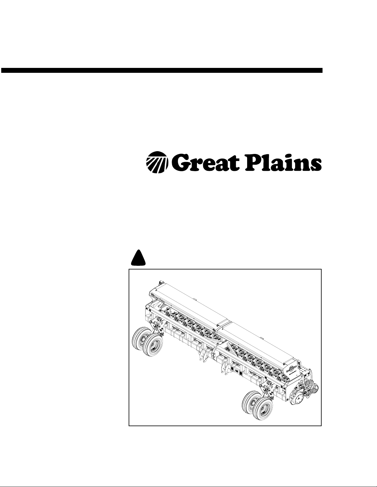
2015P and 2515P
3-Point Precision Bean Machine
Manufacturing, Inc.
www.greatplainsmfg.com
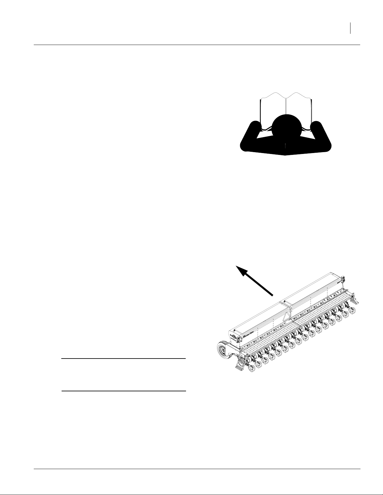
Read the operator’s manual entirely.Whenyouseethissymbol, the subsequent
instructions and warnings are serious - follow without exception. Your life and
!
the lives of others depend on it!
g18394
Cover illustration may show optional equipment not supplied with standard unit.
© Copyright 2000 Printed 4/11/2005
173-208M
Page 2

Table of Contents
Important Safety Information . . . . . . . . . . . . . . . . . . . . . .1
Safety Decals. . . . . . . . . . . . . . . . . . . . . . . . . . . . . . . . 7
Introduction. . . . . . . . . . . . . . . . . . . . . . . . . . . . . . . . . . . 12
Description of Unit . . . . . . . . . . . . . . . . . . . . . . . . . . . 12
Intended Usage . . . . . . . . . . . . . . . . . . . . . . . . . 12
Models Covered . . . . . . . . . . . . . . . . . . . . . . . . . 12
Using This Manual. . . . . . . . . . . . . . . . . . . . . . . . . . . 13
Definitions. . . . . . . . . . . . . . . . . . . . . . . . . . . . . . 13
Owner Assistance . . . . . . . . . . . . . . . . . . . . . . . . . . . 14
Preparation and Setup . . . . . . . . . . . . . . . . . . . . . . . . . . 15
Prestart Checklist. . . . . . . . . . . . . . . . . . . . . . . . . . . . 15
Hitching Tractor to Bean Machine . . . . . . . . . . . . . . . 15
Hydraulic Hose Hookup. . . . . . . . . . . . . . . . . . . . . . . 17
Lift Assist . . . . . . . . . . . . . . . . . . . . . . . . . . . . . . 17
Bleeding Lift Assist Hydraulics. . . . . . . . . . . . . . . . . . 18
Leveling Bean Machine . . . . . . . . . . . . . . . . . . . . . . . 18
Operating Instructions . . . . . . . . . . . . . . . . . . . . . . . . . . 20
Prestart Checklist. . . . . . . . . . . . . . . . . . . . . . . . . . . . 20
Field Operation . . . . . . . . . . . . . . . . . . . . . . . . . . . . . 21
Meter and Sliding Seed Tube . . . . . . . . . . . . . . . 22
Talc Lubricant . . . . . . . . . . . . . . . . . . . . . . . . . . . 22
Graphite Lubricant . . . . . . . . . . . . . . . . . . . . . . . .22
Row Unit Operation . . . . . . . . . . . . . . . . . . . . . . 23
Marker Operation . . . . . . . . . . . . . . . . . . . . . . . . 23
Transporting. . . . . . . . . . . . . . . . . . . . . . . . . . . . . . . . .24
Transporting with Markers . . . . . . . . . . . . . . . . . .24
Transporting with Lift Assist . . . . . . . . . . . . . . . . 24
Parking. . . . . . . . . . . . . . . . . . . . . . . . . . . . . . . . . . . . 25
Adjustments . . . . . . . . . . . . . . . . . . . . . . . . . . . . . . . . . . 26
Row Unit Adjustments . . . . . . . . . . . . . . . . . . . . . . . . 26
Down Pressure. . . . . . . . . . . . . . . . . . . . . . . . . . 26
Coulter Depth . . . . . . . . . . . . . . . . . . . . . . . . . . . 27
Row Unit Seeding Depth . . . . . . . . . . . . . . . . . . 27
Side Gauge Wheels . . . . . . . . . . . . . . . . . . . . . . 28
1 x 12 Closing Wheel Option . . . . . . . . . . . . . . . 29
Closing Disk Option . . . . . . . . . . . . . . . . . . . . . . 30
Frame Height. . . . . . . . . . . . . . . . . . . . . . . . . . . . . . . 30
Seeding Rate. . . . . . . . . . . . . . . . . . . . . . . . . . . . . . . 30
Drive Speed Range Sprockets . . . . . . . . . . . . . . 31
Transmission Sprockets . . . . . . . . . . . . . . . . . . . 31
Shutting Off Seed Flow. . . . . . . . . . . . . . . . . . . . 32
Cleaning Out Meters. . . . . . . . . . . . . . . . . . . . . . 33
Changing Seed Meter Wheels . . . . . . . . . . . . . . 34
Checking Singulated Seeding Rate . . . . . . . . . . 37
Seed rate charts . . . . . . . . . . . . . . . . . . . . . . . . . 37
Marker Adjustments. . . . . . . . . . . . . . . . . . . . . . . . . . 38
Bleeding Marker Hydraulics . . . . . . . . . . . . . . . . 38
Folding Speed with Needle Valves . . . . . . . . . . . 39
Troubleshooting . . . . . . . . . . . . . . . . . . . . . . . . . . . . . . . 45
Maintenance . . . . . . . . . . . . . . . . . . . . . . . . . . . . . . . . . . 50
Options . . . . . . . . . . . . . . . . . . . . . . . . . . . . . . . . . . . . . . 62
Specifications and Capacities. . . . . . . . . . . . . . . . . . . . 65
Seed Rate Charts . . . . . . . . . . . . . . . . . . . . . . . . . . . . . . 66
Appendix . . . . . . . . . . . . . . . . . . . . . . . . . . . . . . . . . . . . . 80
Folding Speed with Sequence Valve . . . . . . . . . 39
Marker Disk Adjustment . . . . . . . . . . . . . . . . . . . 39
Changing disk angle. . . . . . . . . . . . . . . . . . . . . . 39
Leveling marker disk. . . . . . . . . . . . . . . . . . . . . . 40
Transport Carrier . . . . . . . . . . . . . . . . . . . . . . . . 40
Marker Chain (2515P only). . . . . . . . . . . . . . . . . 41
Marker Width . . . . . . . . . . . . . . . . . . . . . . . . . . . 42
Seed-Lok Lock Up. . . . . . . . . . . . . . . . . . . . . . . . . . . 44
Maintenance and Lubrication . . . . . . . . . . . . . . . . . . 50
Meter Maintenance. . . . . . . . . . . . . . . . . . . . . . . 51
Meter Slide Maintenance . . . . . . . . . . . . . . . . . . 51
Chain Tension. . . . . . . . . . . . . . . . . . . . . . . . . . . 53
Inner Sliding Seed Tube Replacement. . . . . . . . 54
Outer Sliding Seed Tube Replacement . . . . . . . 54
Grommet Maintenance. . . . . . . . . . . . . . . . . . . . 55
Drive System . . . . . . . . . . . . . . . . . . . . . . . . . . . 55
Row Unit Disk Spreaders and Scrapers. . . . . . . 55
Row Unit Disks. . . . . . . . . . . . . . . . . . . . . . . . . . 56
Row Unit Side Wheels . . . . . . . . . . . . . . . . . . . . 56
Marker Maintenance. . . . . . . . . . . . . . . . . . . . . . 57
Storage . . . . . . . . . . . . . . . . . . . . . . . . . . . . . . . . . . . 57
Drive Chains. . . . . . . . . . . . . . . . . . . . . . . . . . . . 58
Drive Chains. . . . . . . . . . . . . . . . . . . . . . . . . . . . 58
Lubrication. . . . . . . . . . . . . . . . . . . . . . . . . . . . . . . . . 58
Gauge Wheel Arm Pivots. . . . . . . . . . . . . . . . . . 58
Wheel Bearings . . . . . . . . . . . . . . . . . . . . . . . . . 59
Marker Hinge Points. . . . . . . . . . . . . . . . . . . . . . 59
Side Wheel Arm, Row Unit. . . . . . . . . . . . . . . . . 59
Lift Assist Arm Pivots . . . . . . . . . . . . . . . . . . . . . 60
Lift Assist Castors. . . . . . . . . . . . . . . . . . . . . . . . 60
Marker Disk Bearings. . . . . . . . . . . . . . . . . . . . . 60
Lift Assist Wheel Bearings . . . . . . . . . . . . . . . . . 61
Unit-Mounted Coulter . . . . . . . . . . . . . . . . . . . . . 61
Markers . . . . . . . . . . . . . . . . . . . . . . . . . . . . . . . . . . . 62
Lift Assist. . . . . . . . . . . . . . . . . . . . . . . . . . . . . . . . . . 62
Spring Packages . . . . . . . . . . . . . . . . . . . . . . . . . . . . 63
Coulter. . . . . . . . . . . . . . . . . . . . . . . . . . . . . . . . . . . . 63
Seed-Lok® Firming Wheels . . . . . . . . . . . . . . . . . . . 64
DICKEY-john® Monitor . . . . . . . . . . . . . . . . . . . . . . . 64
Torque Values Chart . . . . . . . . . . . . . . . . . . . . . . . . . 80
Tire Inflation Chart. . . . . . . . . . . . . . . . . . . . . . . . . . . 81
Warranty . . . . . . . . . . . . . . . . . . . . . . . . . . . . . . . . . . 82
© Copyright 2000Allrights Reserved
Great Plains Manufacturing, Inc. provides this publication“as is” without warranty of any kind, either expressed or implied. While every precaution has been takenin the
preparationofthismanual,GreatPlainsMan uf acturing,Inc.assumesno responsibility for errorsoromissions.Neither is any liabilityassumedfordamages resulting from
theuseof the information contained herein. Great Plains Manufacturing,Inc. reservestheright to reviseandimproveits products as it sees fit. This publication describes
the state of this product at the time of its publication, and may not reflect the product in the future.
The following are trademarks of Great Plains Mfg., Inc.: Application Systems, Ausherman, Land Pride, Great Plains
All other brands and product names are trademarks or registered trademarks of their respective holders.
Great Plains Manufacturing, Incorporated Trademarks
Printed in the United States of America.
4/11/2005
173-208M
Page 3

Important Safety Information
Look for Safety Symbol
The SAFETY ALERT SYMBOL indicates there is
apotential hazard to personal safetyinvolvedand
extrasafety precaution must be taken. When you
see this symbol, be alert and carefully read the
message that follows it. In addition to design and
configuration of equipment, hazard control and
accident prevention are dependent upon the
awareness, concern, prudence and proper training of personnel involved in the operation,
transport, maintenance and storage of
equipment.
Important Safety Information
!
1
Be Aware of Signal Wor ds
Signal words designate a degree or level of hazard seriousness.
DANGER indicates an imminently hazardous situation which, if not avoided, will result in death or
serious injury. This signal word is limited to the
most extreme situations, typically for machine
components that, for functional purposes, cannot
be guarded.
WARNINGindicates a potentially hazardous situationwhich, if not avoided,could resultin death or
serious injury, and includes hazards that are exposed when guards are removed. It may also be
used to alert against unsafe practices.
CAUTION indicates a potentially hazardous situation which, if not avoided,may result in minor or
moderate injury. It may also be used to alert
against unsafe practices.
DANGER
!
WARNING
!
CAUTION
!
4/11/2005
173-208M
Page 4
2015P and 2515P
2
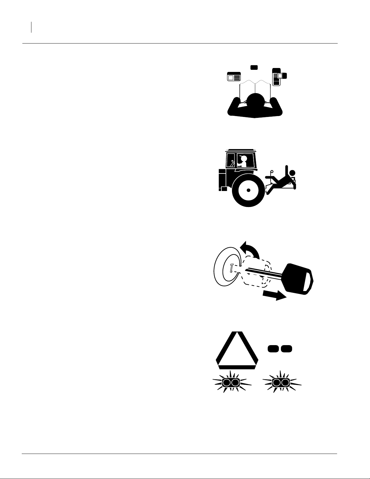
Be Familiar with Safety Decals
▲ Read and understand “Safety Decals,”page 7,
thoroughly.
▲ Read all instructions noted on the decals.
Keep Riders Off Machinery
Riders obstruct the operator’s view. Riders could
be struck by foreign objects or thrown from the
machine.
▲ Never allow children to operate equipment.
▲ Keep all bystanders away from machine dur-
ing operation.
Shutdown and Storage
▲ Lower 3-Point Precision Bean Machine, put
tractor in park, turn off engine, and remove the
key .
▲ Secure 3-Point Precision Bean Machine using
blocks and supports provided.
▲ Detach and store 3-Point Precision Bean
Machine in an area where children normally
do not play.
Use Safety Lights and Devices
Slow-moving tractors and towed implements can
create a hazard when driven on public roads.
They are difficult to see, especially at night.
▲ Use flashing warning lights and turn signals
whenever driving on public roads.
▲ Use lights and devices provided with imple-
ment.
OFF
173-208M
4/11/2005
Page 5
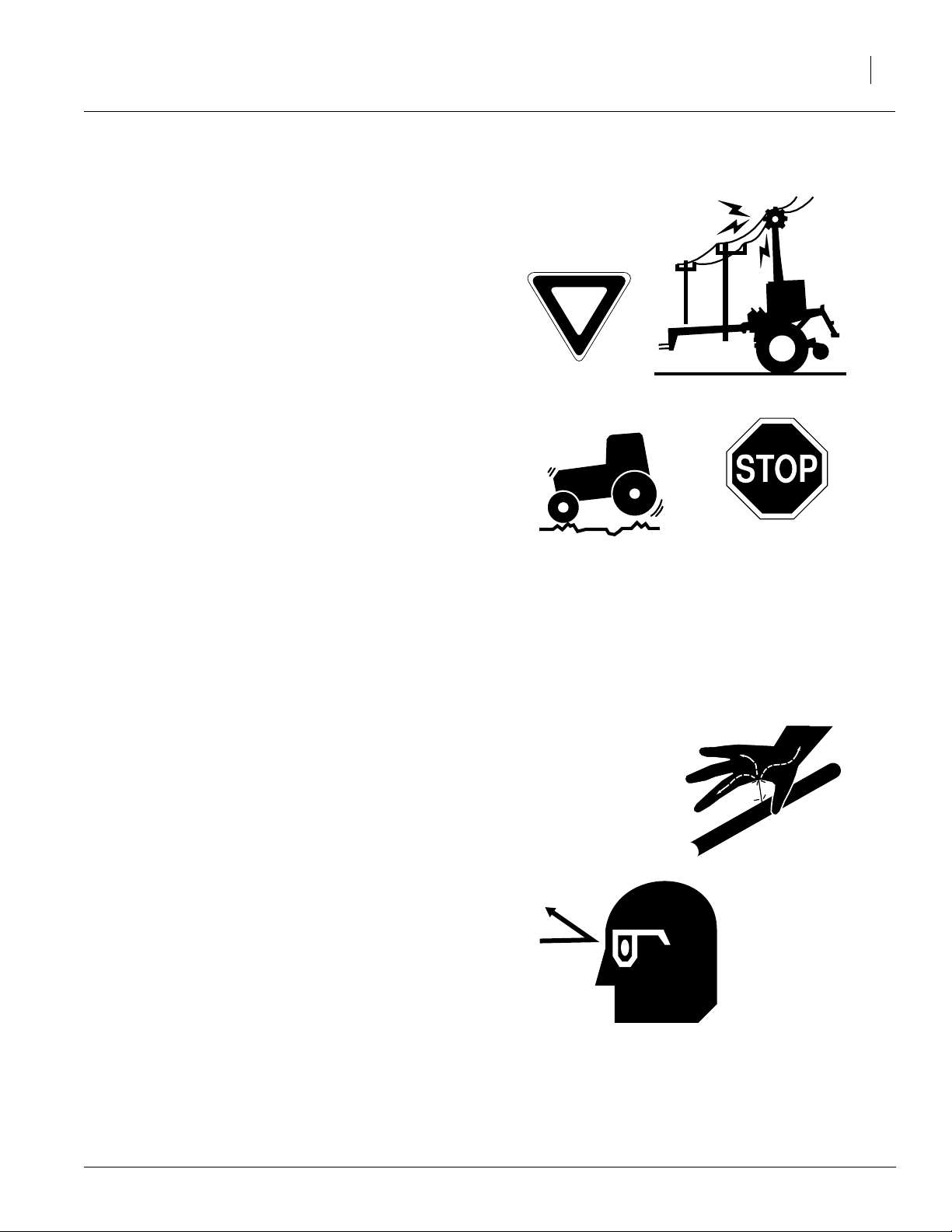
Transport Machinery Safely
Maximum transport speed for implement is 20
mph. Some rough terrains require a slower
speed.Sudden brakingcan cause atowed loadto
swerve and upset.
▲ Do not exceed 20 mph. Never travel at a
speed which does not allow adequate control
of steering and stopping. Reduce speed if
towed load is not equipped with brakes.
▲ Comply with state and local laws.
▲ Do not tow an implement that, when fully
loaded, weighs more than 1.5 times the weight
of towing vehicle.
▲ Carry reflectors or flags to mark 3-Point Preci-
sion Bean Machine in case of breakdown on
the road.
Important Safety Information
3
▲ Keep clear of overhead power lines and other
obstructions when transporting. Refer to transport dimensions under “Specifications and
Capacities,” page 65.
▲ Do not fold or unfold the 3-Point Precision
Bean Machine markers while the tractor is
moving.
Avoid High Pressure Fluids
Escaping fluid under pressure can penetrate the
skin, causing serious injury.
▲ Avoid the hazard by relieving pressure before
disconnecting hydraulic lines.
▲ Use a piece of paper or cardboard, NOT
BODY PARTS, to check for suspected leaks.
▲ Wear protective gloves and safety glasses or
goggles when working with hydraulic systems.
▲ If an accident occurs, see a doctor immedi-
ately. Any fluid injected into the skin must be
surgically removed within a few hours or gangrene may result.
4/11/2005
173-208M
Page 6

2015P and 2515P
4
Practice Safe Maintenance
▲ Understand procedure before doing work. Use
proper tools and equipment. Refer to this manual for additional information.
▲ Work in a clean, dry area.
▲ Lower the 3-Point Precision Bean Machine,
put tractor in park, turn off engine, and remove
key before performing maintenance.
▲ Make sure all moving parts have stopped and
all system pressure is relieved.
▲ Allow 3-Point Precision Bean Machine to cool
completely.
▲ Disconnect battery ground cable (-) before
servicing or adjusting electrical systems or
before welding on 3-Point Precision Bean
Machine.
▲ Inspect all parts. Make sure parts are in good
condition and installed properly.
▲ Remove buildup of grease, oil or debris.
▲ Remove all tools and unused parts from 3-
Point Precision Bean Machine before operation.
Prepare for Emergencies
▲ Be prepared if a fire starts.
OFF
▲ Keep a first aid kit and fire extinguisher handy.
▲ Keep emergency numbers for doctor, ambu-
lance, hospital and fire department near
phone.
Wear Pr otective Equipment
▲ Wear protective clothing and equipment.
▲ Wear clothing and equipment appropriate for
the job. Avoid loose-fitting clothing.
▲ Because prolonged exposure to loud noise
can cause hearing impairment or hearing loss,
wear suitable hearing protection such as earmuffs or earplugs.
▲ Because operating equipment safely requires
your full attention, avoid wearing radio headphones while operating machinery.
173-208M
911
4/11/2005
Page 7
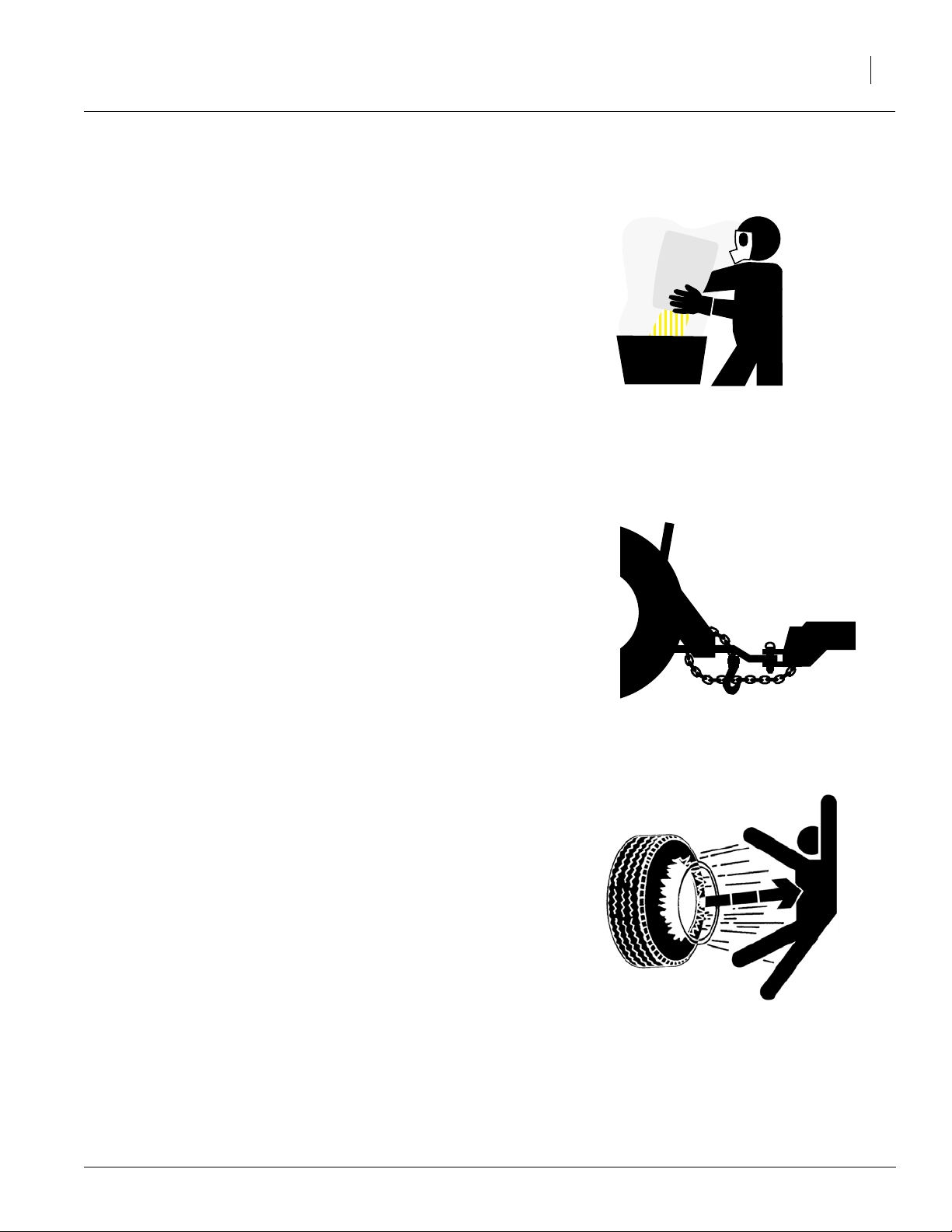
Handle Chemicals Properly
Agricultural chemicals can be dangerous. Improperusecan seriously injurepersons,animals,
plants, soil and property.
▲ Read and follow chemical manufacturer’s
instructions.
▲ Wear protective clothing.
▲ Handle all chemicals with care.
▲ Avoid inhaling smoke from any type of chemi-
cal fire.
▲ Store or dispose of unused chemicals as
specified by chemical manufacturer.
Use A Safety Chain
▲ Use a safety chain to help control drawn
machinery should it separate from tractor
drawbar.
Important Safety Information
5
▲ Use a chain with a strength rating equal to or
greater than the gross weight of towed
machinery.
▲ Attach chain to tractor drawbar support or
other specified anchor location. Allow only
enough slack in chain to permit turning.
▲ Replace chain if any links or end fittings are
broken, stretched or damaged.
▲ Do not use safety chain for towing.
Tire Safety
Tire changing can be dangerous and should be
performed by trained personnel using correct
tools and equipment.
▲ When inflating tires, use a clip-on chuck and
extension hose long enough for you to stand
to one side–not in front of or over tire assembly. Use a safety cage if available.
▲ When removing and installing wheels, use
wheel-handling equipment adequate for
weight involved.
4/11/2005
173-208M
Page 8
2015P and 2515P
6
Safety At All Times
Thoroughly read and understand the instructions
in this manual before operation. Read all instructions noted on the safety decals.
▲ Be familiar with all 3-Point Precision Bean
Machine functions.
▲ Operate machinery from the driver’s seat only.
▲ Do not leave 3-Point Precision Bean Machine
unattended with tractor engine running.
▲ Do not dismount a moving tractor. Dismount-
ing a moving tractor could cause serious injury
or death.
▲ Do not stand between the tractor and 3-Point
Precision Bean Machine during hitching.
▲ Keep hands, feet and clothing away from
power-driven parts.
▲ Wear snug-fitting clothing to avoid entangle-
ment with moving parts.
▲ Watch out for wires, trees, etc., when folding
markers and raising 3-Point Precision Bean
Machine. Make sure all persons are clear of
working area.
▲ Do not turn tractor too tightly, cause 3-Point
Precision Bean Machine to ride up on wheels.
This could cause personal injury or equipment
damage.
173-208M
4/11/2005
Page 9
Important Safety Information
7
Safety Decals
Your implement comes equipped with all safety
decals in place. They were designed to help you
safely operate your implement.
▲ Read and follow decal directions.
▲ Keep all safety decals clean and legible.
▲ Replace all damaged or missing decals. Order
new decals from your Great Plains dealer.
Refer to this section for proper decal placement.
▲ When ordering new parts or components, also
request corresponding safety decals.
▲ To install new decals:
1. Cleanthe areaonwhich the decalis tobe
placed.
2. Peel backing from decal. Press firmly on
surface, being careful not to cause air
bubbles under decal.
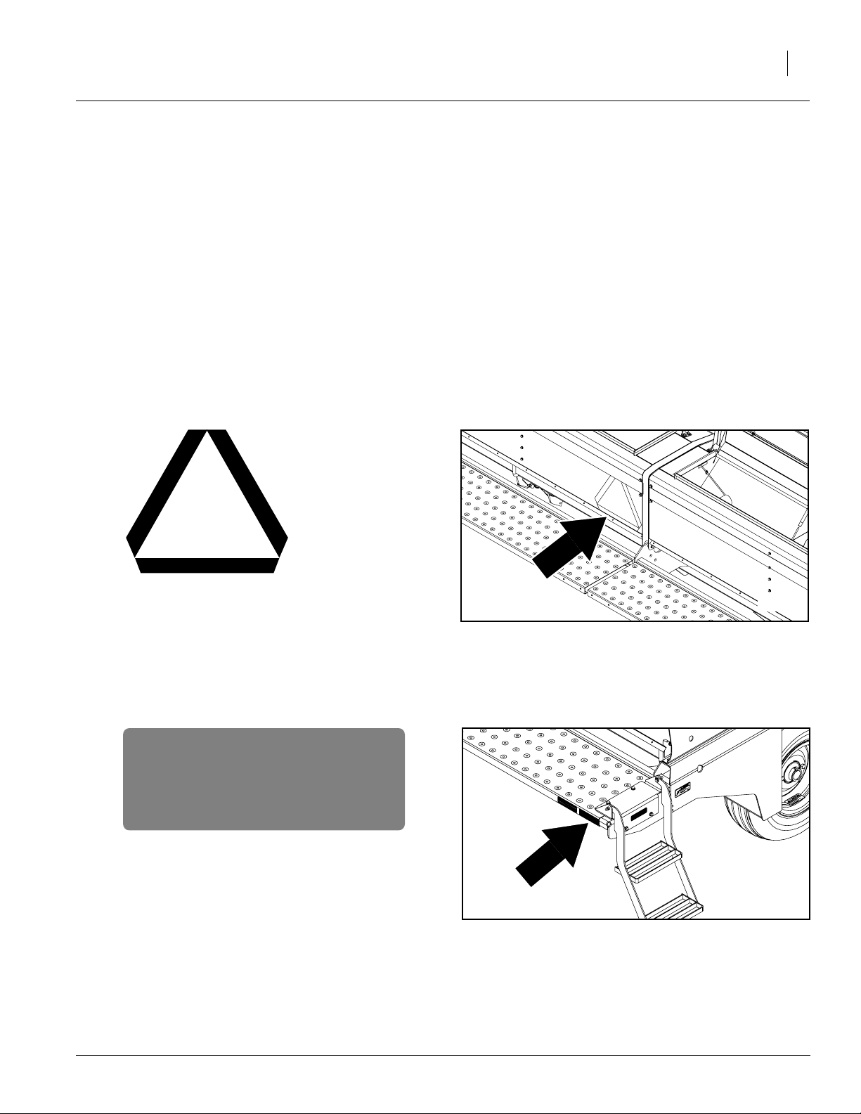
818-003C
Slow Moving Vehicle Sign
838-266C
Red Reflectors
Reflector on both ends of bean machine;
two reflectors total.
17769
17769
4/11/2005
173-208M
Page 10
2015P and 2515P
8
838-265C
Amber Reflectors
Reflectorson both ends ofbeanmachine;
four reflectors total.
18542
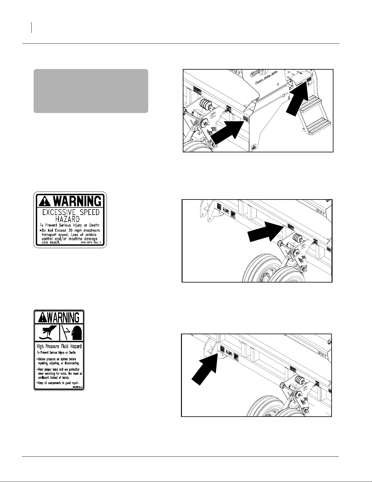
818-337C
Excessive Speed Hazard
818-339C
High Pressure Fluid Hazard
18542
18542
173-208M
4/11/2005
Page 11
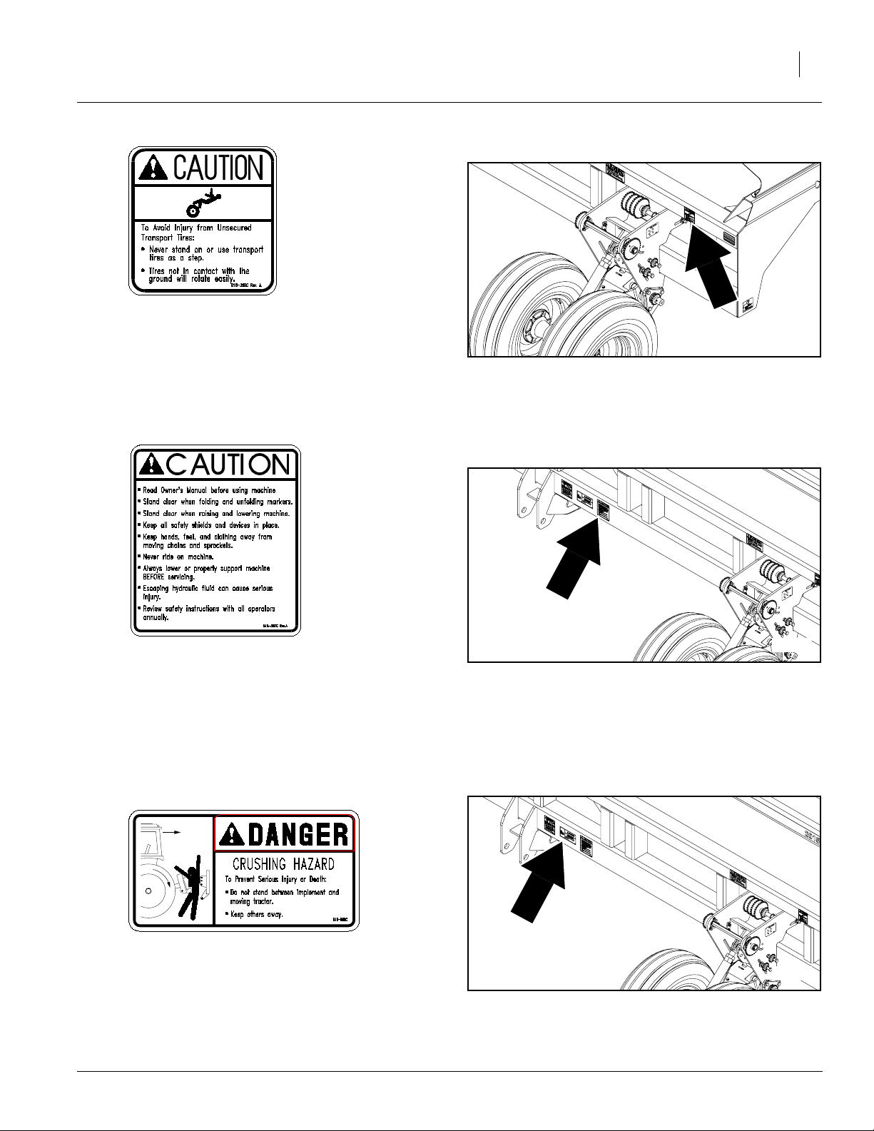
818-398C
Caution Tires Not a Step
Important Safety Information
18542
9
818-587C
Caution Operational
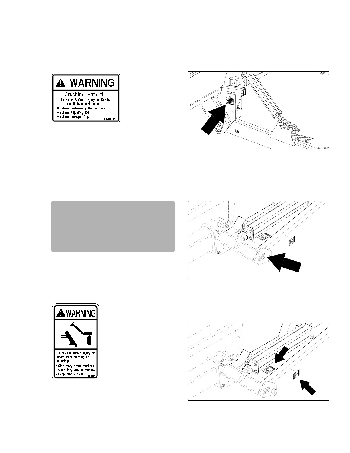
818-590C
Crushing Hazard
18542
18542
4/11/2005
173-208M
Page 12
2015P and 2515P
10
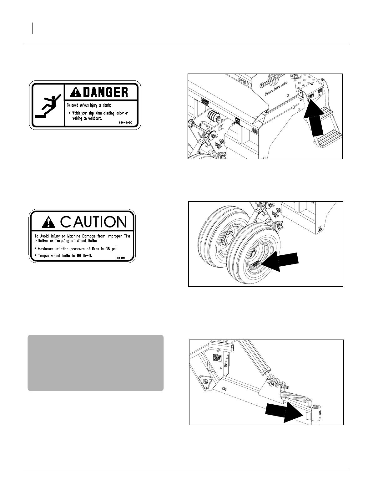
838-102C
Falling Hazard
18542
818-855C
Caution Tire 36 PSI
838-265C
Amber Reflector
Reflector on each optional lift-
assist arm; two reflectors total
18542
17770
173-208M
4/11/2005
Page 13
838-057C
Crushing Hazard
Important Safety Information
17770
11
838-265C
Amber Reflector
Reflector on each optional marker
818-682C
Warning Pinch/Crush Marker
17843
17843
4/11/2005
173-208M
Page 14
2015P and 2515P
12
Introduction
GreatPlains welcomesyouto itsgrowingfamilyof
newproduct owners. This 3-Point Precision Bean
Machinehas beendesignedwith careandbuiltby
skilled workers using quality materials. Proper
setup, maintenance and safe operating practices
willhelp you get yearsof satisfactory use from the
machine.
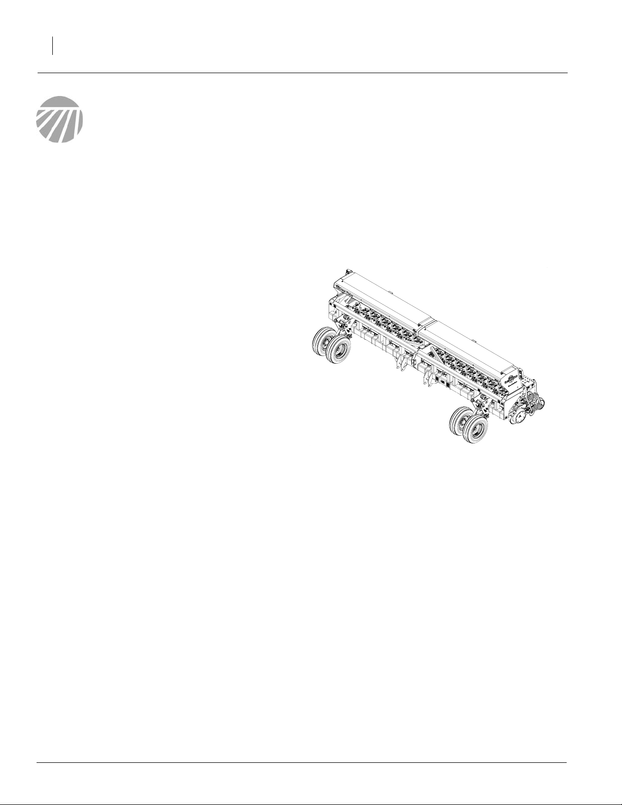
Description of Unit
The 2015P and 2515P model bean machines are
3-point mounted precision seeding bean machines equipped with double-disk, planter-style
rowunits.Seeding depth, closing wheel pressure
and row unit down force can be adjusted.
Intended Usage
Use the bean machine to seed production-agriculture crops only. Do not modify the bean
machine for use with attachments other than
Great Plains options and accessories specified
for use with the bean machine.
Models Covered
2015P and 2515P
18394
173-208M
4/11/2005
Page 15
Using This Manual
This manual will familiarize you with safety, assembly, operation, adjustments, troubleshooting
and maintenance. Read this manual and follow
the recommendations to help ensure safe and efficient operation.
The information in this manual is current at printing. Some parts may change to assure top
performance.
Definitions
The following terms are used throughout this
manual.
Singulated Seeds - seeds that are metered individually, such as soybeans, corn, cotton and milo.
The seed meter separates individual seeds from
the seed pool and distributes them one at a time.
The seed rates are designated as seeds per acre.
Introduction
13
Sliding seed tubes - telescoping tubes which connect the seed box and seed meters.
Seed meter - the component which separates the
seeds for distribution.
Seed meter wheel - a changeable wheel inside
the seed meter with small pockets for separating
seeds.
Seed wheel pockets - indentations on the seed
meterwheel which collect seedsfor distributionto
the opener seed tube.
Right-hand and left-hand as used in this manual
are determined by facing the direction the machine will travel while in use unless otherwise
stated.
IMPORTANT: A crucial point of information related to the preceding topic. For safe and correct operation, read and follow the directions
provided before continuing.
NOTE: Useful information related to the preceding topic.
Machine travel
direction
Left-hand
side
Right-hand
side
18540
4/11/2005
173-208M
Page 16

2015P and 2515P
14
Owner Assistance
If you need customer service or repair parts, contact a Great Plains dealer. They have trained
personnel, repair parts and equipment specially
designed for Great Plains products.
Refer to Figure 1
Yourmachine’spartswerespecially designedand
should only be replaced with Great Plains parts.
Alwaysuse the serial and model number when ordering parts from your Great Plains dealer. The
serial-number plate is located on the front left
hand end.
Record your bean machine model and serial number here for quick reference:
Model Number:__________________________
Serial Number: ___________________________
Your Great Plains dealer wants you to be satisfied
with your new machine. If you do not understand
anypartof thismanual orare not satisfiedwith the
service received, please take the following
actions.
1. Discuss the matter with your dealership service manager. Make sure they are aware of
any problems so they can assist you.
2. If you are still unsatisfied, seek out the owner
or general manager of the dealership.
3. For further assistance write to:
Product Support
Great Plains Mfg. Inc., Service Department
PO Box 5060
Salina, KS 67402-5060
Figure 1
Serial Number Locations
18455
173-208M
4/11/2005
Page 17

Preparation and Setup
Thissection will help youprepareyour tractor and
3-Point Precision Bean Machine for use. Before
using the 3-Point Precision Bean Machine in the
field, you must hitch the bean machine to a suitabletractor(see“TractorRequirements,”page65)
and level the bean machine.
Prestart Checklist
1. Readand understand “ImportantSafetyInformation,” page 1.
2. Check that all working parts are moving freely, bolts are tight, and cotter pins are spread.
Preparation and Setup
15
3. Checkthat all grease fittings are in place and
lubricated. Refer to “Lubrication,” page 58.
4. Checkthatallsafety decalsand reflectors are
correctly located and legible. Replace if damaged. See “Safety Decals,” page 7.
5. Inflate tires to pressure recommended and
tighten wheel bolts as specified. See “Appendix,” page 80.
Hitching T ractor to Bean Machine
!
DANGER
You may be severelyinjured or killed by being crushed
betweenthe tractor and bean machine.Donot standor
place any part of your body between bean machine
and moving tractor. Stop tractor engine and set park
brake before installing the hitch pin.
1. Allowlowerthree-point links on tractor to float
independent of each other. Do not pin lower
links together.
2. Raise or lower tractor three-point arms as
needed and pin tractor lower links to bean
machine.
4/11/2005
Refer to Figure 2
Category II and III tractors with quick
hitch: Use pins provided with bean machine.
Discard bushings provided with bean machine.
Figure 2
Category II and III Tractors with Quick Hitch
18550
173-208M
Page 18
2015P and 2515P
16
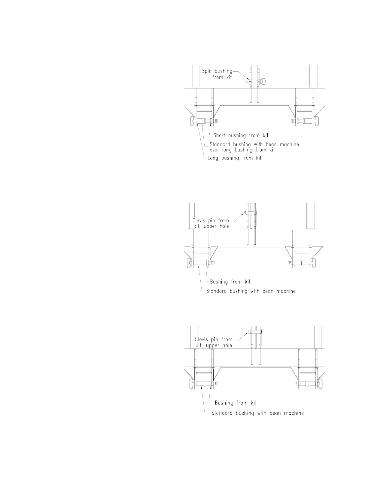
Refer to Figure 3
Category II tractors, no quick hitch: Discard pins provided with bean machine. Order
Great Plains kit, part number 173-170A. Use
pins and bushings as shown. See Figure 4.
Category III tractors, no quick hitch: Use
pins provided with bean machine. Use bushings provided with bean machine to space
lower tractor links to the outside.
Refer to Figure 4
Figure 3
17984
Category II Tractors, No Quick Hitch
Category IV tractors with Cat IV-N quick
hitch: Discard upper pin provided with bean
machine.Use other pinsand bushings provided with bean machine. Also, order Great
Plains kit, part number 173-171A. Use pins
and bushings as shown.
Refer to Figure 5
Category IV tractors, no quick hitch: Discard upper pin provided with bean machine.
Use other pins and bushings provided with
bean machine. Also, order Great Plains kit,
part number173-171A. Usepins andspacers
as shown.
1. Pin top three-point link to bean machine.
Figure 4
Category IV Tractors with Quick Hitch
17986
NOTE: If bean machine is outfitted with optional
lift assist, operate tractor and bean machine without tractor top link. On quick hitches, pin quick
hitch tobeanmachineandremovetractor top link.
2. Slowly raise bean machine. Watch for cab interference.
173-208M
Figure 5
Category IV Tractors, No Quick Hitch
17985
4/11/2005
Page 19
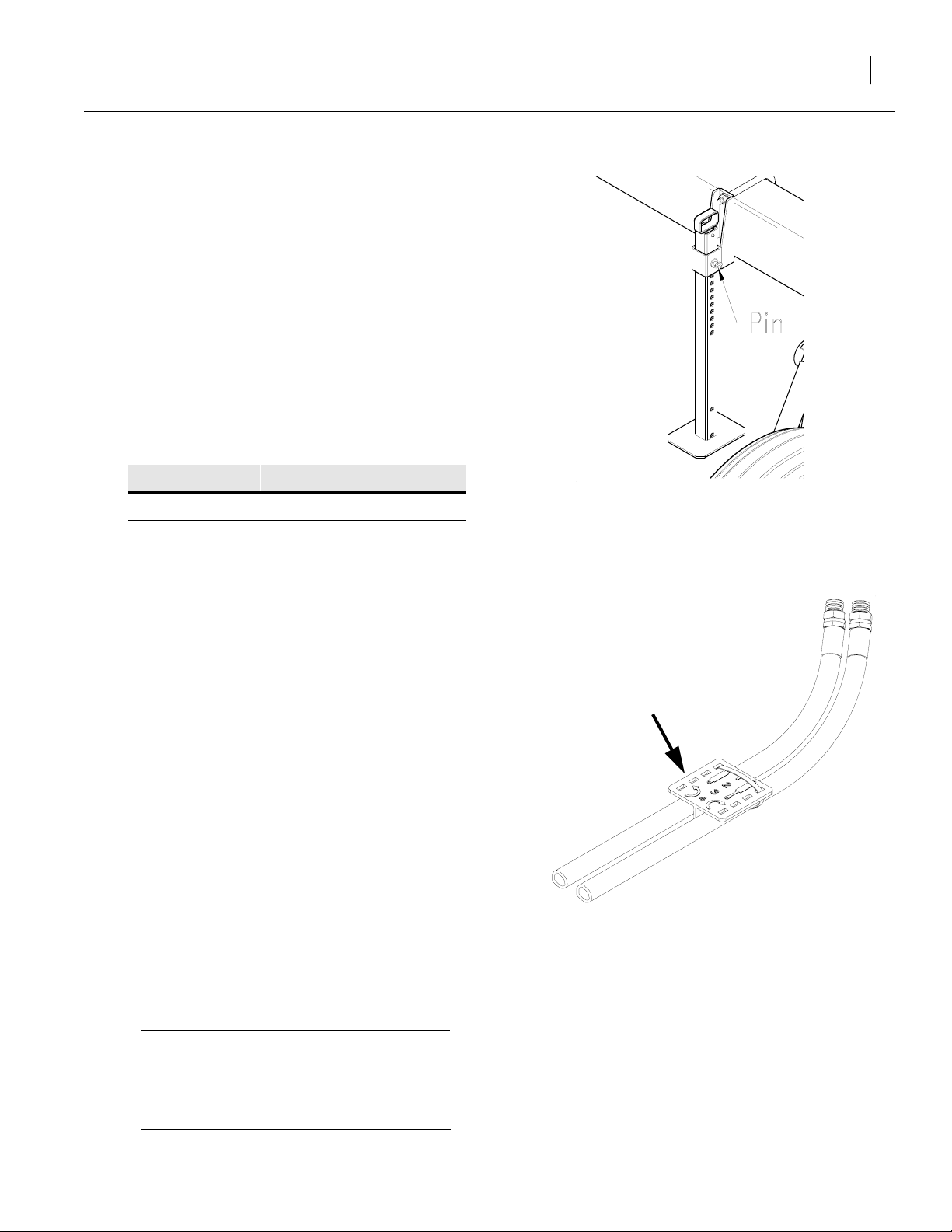
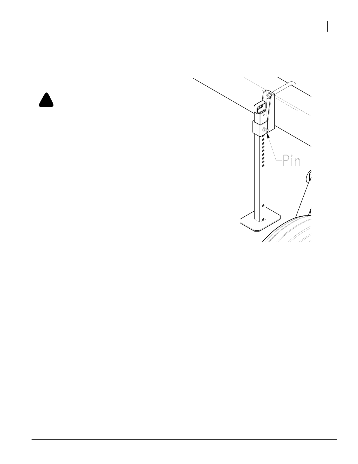
Refer to Figure 6
3. Remove pins holding parking stands and
raise stands. Replace pins in lowest hole in
each stand.
4. Set your tractor three-point-draft control to
float position.
5. Plug lead from bean machine light harness
into tractor receptacle.
Hydraulic Hose Hookup
Great Plains hydraulic hoses are color coded to
help you hookup hoses to your tractor outlets.
Hoses that go to the same remote valve are
marked with the same color.
Color Hydraulic Function
Red Field Lift Cylinders
Orange Marker Cylinders
Preparation and Setup
Figure 6
Parking Stand
17
13508
Refer to Figure 7
To distinguishhoseson thesame hydrauliccircuit,
referto plastic hose holder.Hose under extendedcylinder symbol feeds cylinder base ends. Hose
under retracted-cylinder symbol feeds cylinder
rod ends.
Lift Assist
Hydraulics for the optional lift assist can be
plumbed three different ways.
• Tractor remote valve drives lift assist alone
• Tractor remote valve drives lift assist and
three-point hitch
• Tractor hydraulic circuit for three-point hitch
drives lift assist and three-point hitch
To operate the lift assist on its on remote valve,
plug hydraulic hoses into valve outlets.
To plumb together the lift-assist and three-point
hydraulics,contact your tractor dealer for specific
instructions.
Hose label
Figure 7
Hydraulic Hose Label
17641
4/11/2005
IMPORTANT: Before plumbing the lift assist
into your tractor three-point circuit, contact
your tractor dealer for detailed instructions.
Failure to properly plumb the hydr aulics can
cause tractor damage.
173-208M
Page 20
2015P and 2515P
18
Bleeding Lift Assist Hydraulics
!
WARNING
Crushing hazard. The hydraulics could fail, causing
the bean machine to fall and crush you. Never work
under the raised bean machine unless secured with
channel locks. Never bleed an O-ring fitting, which
could damage the seal and cause the implement to
drop rapidly.
The lift-assist hydraulics must be free of air.If the
lift assist raises with jerky, uneven motions, or if a
hydrauliccomponent is replaced during the life of
the lift assist, follow these steps to bleed air from
the hydraulics.
1. Check that the tractor hydraulic reservoir is
full.
Loosen
Loosen
Figure 8
Lift Assist Hydraulic Tee Fitting
18554
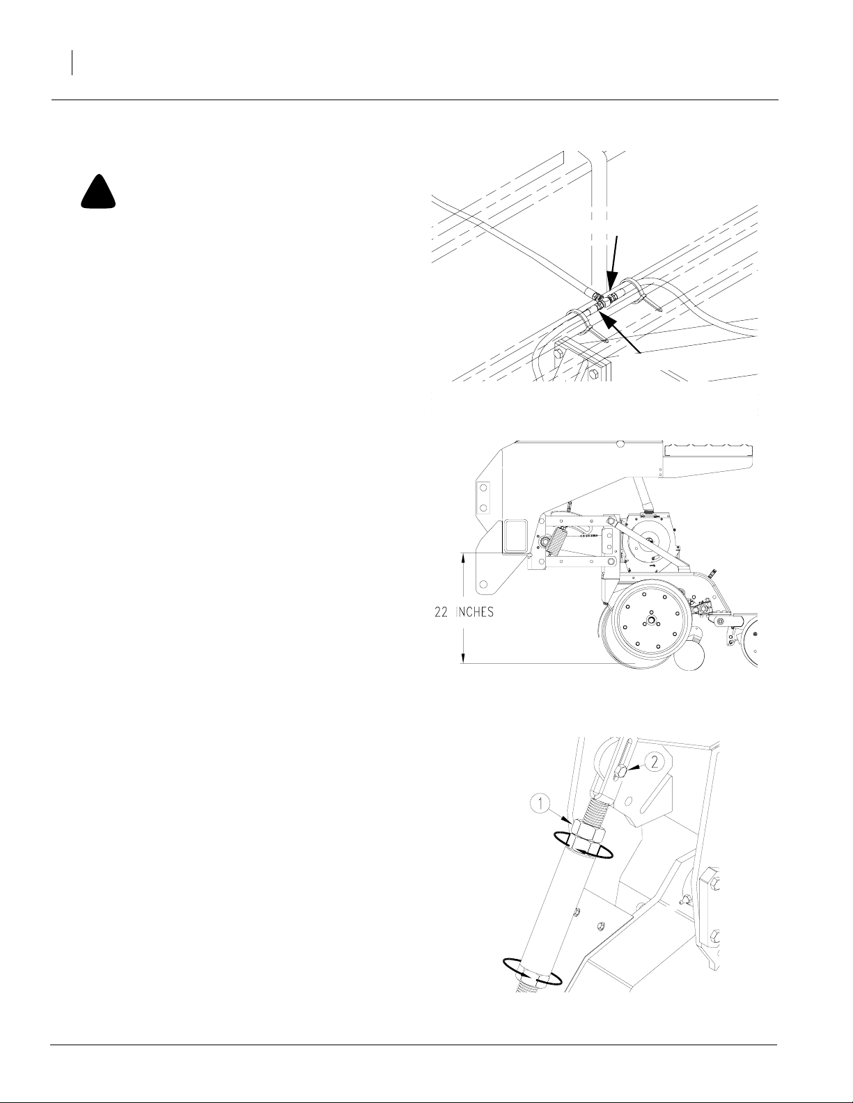
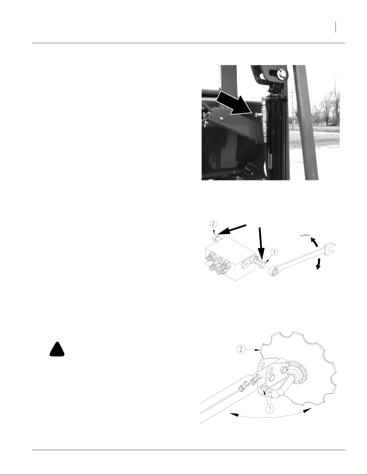
Refer to Figure 8
2. Loosenteefittingon bothsides of thetee. Tee
fitting is located under bean machine box.Engage tractor hydraulic lever for the lift assist
until oil appears at loosened fittings. Tighten
fittings.
Leveling Bean Machine
Refer to Figure 9
Adjust bean machine so opener tube runs 22
inches above ground when bean machine is lowered in field.
Refer to Figure 10
1. Loosen jam nut (1) near top clevis of each
gauge-wheel turnbuckle.
NOTE: Jam nut is left-hand threaded.
2. Bolt upper clevis in upper mount hole (2).
3. Set turnbuckle length. Turn turnbuckle to
shortenorlengthen as necessary. Initially set
lengthto 151/4 inchesbetween pincenters to
achievethe 22-inch dimension mentioned
above.When adjusting turnbuckle, remember:
Figure 9
Initial Operating Height
18543
• Lengthening turnbuckle raises bean machine.
• Shortening turnbuckle lowers bean machine.
4. After adjusting both turnbuckles to same
length, tighten jam nuts.
173-208M
Figure 10
17773
Gauge-Wheel Turnbuckle
4/11/2005
Page 21
5. Ifusing the bean machine without optional lift
assist, level bean machine with top threepoint link. Shorten or lengthen link until the
top of the bean machine box is parallel with
the ground.
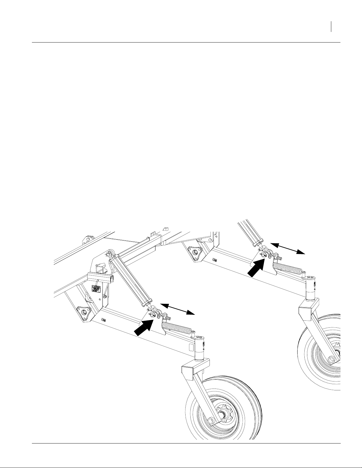
6. Ifusing bean machine withoptional lift assist,
useeyeboltadjustmenton lift-assist cylinders
to level bean machine.
Refer to Figure 11
With the row-unit springs at the lightest setting, loosen jam nutsand shorten or lengthen
eyebolts until top of bean machine boxis leveland lift-assistcylinders collapsecompletely
when bean machine is lowered. To raise or
lower bean machine, adjust eyebolts.
Preparation and Setup
19
Raise
Raise
Lower
Lower
4/11/2005
Figure 11
Eyebolt Adjustment for Lift Assist
17770
173-208M
Page 22

2015P and 2515P
20
Operating Instructions
This section covers general operating procedures. Experience, machine familiarity and the
following information will lead to efficient operation and good working habits. Always operate
farm machinery with safety in mind.
Prestart Checklist
!
WARNING
Escaping fluid under pressure can have sufficient pressure to penetrate the skin. Check all hydraulic lines
and fittings before applying pressure. Fluid escaping
froma very small hole can be almost invisible.Use paper or cardboard, not body parts, and wear heavy
gloves to check for suspected leaks. If injured, seek
medical assistance from a doctor that is familiar with
this type of injury. Foreign fluids in the tissue must be
surgically removed within a few hours or gangrene
will result.
1. Carefullyread “Important SafetyInformation,”
page 1.
2. Lubricate bean machine as indicated under
“Lubrication,” page 58.
3. Check all tires for proper inflation. See “Appendix,” page 80.
4. Checkall bolts, pinsandfasteners. Torque as
shown in “Appendix,” page 80.
5. Check bean machine for worn or damaged
parts. Repair or replace parts before going to
the field.
6. Check hydraulic hoses, fittings and cylinders
for leaks. Repair or replace before going to
the field.
7. Rotate both gauge wheels to see that the
drive and meters are working properly and
free from foreign material.
!
DANGER
Watchyourstep when walkingon bean machineladder
and walkboard. Falling from bean machine could
cause severe injury or death.
173-208M
4/11/2005
Page 23

Field Operation
!
DANGER
You may be severelyinjured or killed by being crushed
betweenthe tractor and bean machine.Donot standor
place any part of your body between bean machine
and moving tractor. Stop tractor engine and set park
brake before installing pins.
Hitch bean machine to a suitable tractor or hitch.
Refer to “Hitching Tractor to Bean Machine,”.
Refer to Figure 12
1. Make sure proper seed meter wheels are in
place. For information on how to change the
seed meter wheels see page 34.
Refer to Figure 13
2. Makesure all seed meter clean out doors are
closed and pinned. Formore information see
page 33.
3. Set seeding rate as explained in “Seeding
Rate”, page 30.
Seed
meter
wheel
Operating Instructions
Figure 12
Seed meter wheel in place
Seed meter
clean out door
21
19190
Refer to Figure 14
4. Open and pin sliding seed tubes. For further
information see page 32.
5. Adjust row unit for necessary down pressure
and desired seeding depth. Refer to “Adjustments”, page 26.
6. If bean machine has optional lift assist, lower
bean machine in the field and check that liftassist cylinders are retracted fully. If not, add
weights to weight brackets until cylinders retract completely.
7. Load box with clean seed and talc.
8. Raise bean machine. Rotate gauge wheel.
Check that seed meters, seed tubes and
drives are working properly and free from foreign material by looking for seed flow under
each row opener.
9. Record acremeter readout. Subtract initial
reading from later readings to determine
acres planted.
10. Pull forward, lower bean machine and begin
seeding.
Retaining
clip
Figure 13
Seed meter clean out door in closed position
Sliding seed
tubes
18261
11. Always lift bean machine out of the ground
when turning at row ends and for other shortradius turns. Seeding will stop automatically
as bean machine is raised.
4/11/2005
Figure 14
Sliding seed tubes in open position
18448
173-208M
Page 24

2015P and 2515P
22
Meter and Sliding Seed Tube
Refer to Figure 15
Figure 15 shows the seed meter and seed tubes.
Before operation, make sure you are using the
correct seed meter wheel for the seed you are
using.
For information on meter adjustments, refer to
“Seeding Rate”, page 30.
If your bean machine has been exposed to the elementsfor aperiodof time withseedin the boxes,
check to make sure the seed in the seed tubes
and meters has not become wet.
Seed tube
Seed
meter
Opener
seed tube
Sliding
Figure 15
Seed Meter
Spring-loaded
idler
18458
Talc Lubricant (821-046C)
IMPORTANT!
All talc is not created equal, use Great Plains
brand talc for optimum seed flow.
Talc lubricant is mandatory forall seeds, especially treated or inoculated seed.
Recommended usage:
For clean seeds sprinkle (1) one cup of talc per 3
bushels of seed.
For seed with excessive treatment, or for humid
plantingenvironments,double ortriple talc rateas
needed.
!
CAUTION
Do not use hands or any part or your body to mix talc
lubricant.
Graphite Lubricant (821-042C)
IMPORTANT!
For Milo Planting Only
Powdergraphitemust bemixedwith themiloseed
in combination with talc for proper seed
singulation.
Recommended usage:
For clean seeds sprinkle (1) one cup of graphite
per 9 bushels of seed.
For seed with excessive treatment, or for humid
planting environments, double or triple graphite
rate as needed.
!
CAUTION
Do not use hands or any part of your body to mix
graphite lubricant.
173-208M
4/11/2005
Page 25

Row Unit Operation
IMPORTANT: Do not back up with row units in
the ground. To do so will cause severe damage and plugging.
For information on row unit adjustments, refer to
page26. Formore information on troubleshooting
row unit problems, see “Troubleshooting”, page
45.
Marker Operation
Optional marker attachments are available from
your Great Plains dealer. Before operating markers, make sure hydraulics are properly bled as
described under “Marker Adjustments”, page 38.
Dualmarkersequippedwith asequence valveare
powered off the same hydraulic circuit. Starting
with both markers folded,the foldingsequence is:
Operating Instructions
23
1. Activate lever - Right unfolds; left stays
folded.
2. Reverselever- Right folds up; left stays
folded.
3. Activate lever - Left unfolds; right stays
folded.
4. Reverse lever - Left folds up; right stays
folded.
5. Sequence repeats.
You can adjust marker folding speed. Refer to
“MarkerAdjustments”,page 38,andadjustfolding
speed to a safe rate. Folding markers at high
speed can damage markers.
4/11/2005
173-208M
Page 26

2015P and 2515P
24
Transporting
!
WARNING
Towing the bean machine at high speeds or with a vehicle that is not heavy enough could lead to loss of vehicle control. Loss of vehicle control could lead to
seriousroadaccidents, injuryand death. Toreduce the
hazard,do not exceed 20 mph. Check that your tractor
has enough ballast to handle the weight of the bean
machine. Refer to your tractor operator’s manual for
ballast requirements.
Beforetransporting the bean machine, followand
check these items:
Unload seed box. Unload seed boxbefore transporting if at all possible. To do so:
• Place tarp under bean machine or a bucket
under each seed meter.
• Use large bucket to empty box as much as
possible. Make sure sliding seed tubes are in
theopen position. Openseed meter cleanout
to empty seed out of sliding seed tube and
meter.
The bean machine can be transported with a full
box of grain, but the added weight will increase
stopping distance and decrease maneuverability.
NOTE: To maintain steering control, you may
needto add ballast to your tractorfront end. Refer
to your tractor operator’s manual for ballast required.
Road rules. Comply with all federal, state and local safety laws when travelingon public roads.
Refer to Figure 16
Clearance. Remember that the bean machine is
wider than the tractor. Allow safe clearance. Fold
up walkboard ladder for maximum clearance.
Transporting with Markers
Always transport markers in the folded position.
Figure 16
Ladder Folded for Transport
18456
Refer to Figure 17
Transporting with Lift Assist
Before transporting or servicing bean machine,
install cylinder lock channels over extended cylinder rods.
During field use, store lock channels on side
plates of lift-assist arms.
173-208M
Figure 17
Lock Channels
17733
4/11/2005
Page 27
Parking
See ”Storage”, page 57 for additional information
on long-term storage.
!
WARNING
Empty seed box before unhitching bean machine to
prevent bean machine from falling backward.
1. Park bean machine on a level, solid area.
2. Lowerthree-point hitch until bean machine is
on ground.
Refer to Figure 18
3. Removepins from parking stands and lower
standsto the ground. If groundissoft, place a
board or plate under stands to increase contact area. Replace pins in stands.
25
4. Extendorretract thetop link ofthe tractoruntil
top three-point pin is free. Remove pin.
5. Removepins from lower links.
13508
Figure 18
Parking Stand
4/11/2005
173-208M
Page 28

2015P and 2515P
26
Adjustments
Row Unit Adjustments
Down Pressure
Springs providethe down pressure necessary for
rowunit disks to open a seed trench. The springs
allow the row unit to float down into depressions
and up over obstructions.
You can adjust down pressure individually for
eachrow unit. Use onlyenoughdown pressure to
cut the seed trench and maintain proper soil-firming overseed. Excessivedown pressure will lead
to premature wear on row-unit components.
Refer to Figure 19
To adjust, lift T-handle:
• Move T-handle back to increase spring pressure.
• Move T-handle ahead toward tractor to decrease spring pressure.
Refer to the Down Pressure Charts on the right
for the amount of spring pressure at the row unit
for each spring setting.
Medium-Duty Spring Package
First Holes (Closest to Tractor) 260 lb
Second Holes 280 lb
Third Holes 310 lb
Fourth Holes 330 lb
Fifth Holes (Closest to Press Wheels) 350 lb
Heavy-Duty Spring Package
First Holes (Closest to Tractor) 360 lb
Second Holes 400 lb
Third Holes 440 lb
Fourth Holes 470 lb
Fifth Holes (Closest to Press Wheels) 530 lb
Down Pressure Charts
173-208M
Increase
spring pressure
Down pressure
T-handle
Decrease
spring pressure
Figure 19
Row Unit Spring Adjustment
Front of bean
machine
18449
4/11/2005
Page 29

Coulter Depth
Optional coulters allow bean machine to penetrate tough ground conditions. Adjust coulters to
the same depth as the row unit disks.
Refer to Figure 20
1. To adjust coulter depth, loosen 3/4-inch jam
nut (1) and 3/4-by-3-inch hex bolt (2).
2. Byturning camhex(3), rotatethe camcasting
to the desired height. Each notch represents
about 1/4 inch of depth.
3. Torque bolt and jam nut to values recommended in the “Appendix,” page 80.
Row Unit Seeding Depth
Seeding depth is controlled by gauge wheels
mounted on the sides of the row unit disks.
Figure 20
Row Unit Mounted Coulter
Adjustments
15053
27
Refer to Figure 21
To adjust seeding depth:
1. Raise bean machine to remove weight from
gauge wheels.
2. Raise and move T-handle.
• Move T-handle ahead to decrease seeding
depth.
• Move T-handle back to increase seeding
depth.
3. MoveT-handles on all row units to the same
location.
T-handle
Increase
seeding depth
Opener Depth Adjustment
Figure 21
Decrease
seeding depth
18459
4/11/2005
173-208M
Page 30

2015P and 2515P
28
Side Gauge Wheels
Refer to Figure 22
The side gauge wheels have two, interrelated
adjustments:
• angle of side gauge wheel, and
• distance between side gauge wheel and row
unit disk.
Refer to Figure 23
Side Gauge
Wheel
Opener
Disks
Side Gauge
Wheel
Adjust side-gauge-wheel angle so the wheels
contact the row unit disks between 4 and 8
o’clock.
At the same time, keep the side gauge wheels
close to the opener disks so openers do not plug
with soil or trash but far enough out so the disks
and wheels turn freely.
Refer to Figure 24
To adjust side gauge wheels:
1. Raise implement slightly to remove weight
from side gauge wheels.
2. Loosen hex-head bolt (1). Move wheel and
arm out on o-ring bushing.
3. Loosenpivot bolt (2). Turn hex adjuster (3) so
roll pin (4) is at 1 o’clock. Use this as the starting point for adjustment.
4. Movewheel arm in so side gauge wheel contacts row unit disk. Tighten hex-head bolt (1)
to clamp arm around bushing and shank.
8 o’clock
Incorrect Correct
Figure 22
Side Gauge Wheels
4 o’clock
17812
Figure 23
Wheel-to-Disk Contact Area
5. Check the wheel-to-disk contact. Lift wheel
and arm. When let go, the wheel should fall
freely.
• If wheel does not contact disk from 4 to 8
o’clock, move hex adjuster until wheel is an-
gled for proper contact with disk.
• If wheel does not fall freely, loosen hexheadbolt (1) andslide wheel armout just until
wheel and arm move freely. Retighten hexhead bolt.
6. Keepturning hex adjuster and moving wheel
arm until the wheel is adjusted properly.
When satisfied, tighten pivot bolt to 110 footpounds. Tighten pivot bolt (2).
173-208M
1
Starting Point
Side Gauge Wheel Adjustment
3
2
4
18450
Figure 24
4/11/2005
Page 31
1 x 12 Closing Wheel Option
The closing wheels can be adjusted for down
pressure, alignment and offset.
Down Pressure. Adjust closing wheel so it has
enough down force to close the seed trench without unnecessary compaction.
Refer to Figure 25
Starting
position
Adjustments
29
Start with T-handle in first notch. If seed trench
doesnotclose, move handle tonextnotch and try
again.Keepmoving handleback untilseed trench
closes.
Alignment. If one closing wheel is running in the
seed trench or closing wheels are not centered
over the seed trench, adjust closing wheels as
follows.
Refer to Figure 26
1. Raisebeanmachineslightly toremoveweight
from closing wheels.
2. Loosen two 1/2-inch mounting bolts (1).
3. Turn adjuster cam (2) left or right to center
wheels over the seed trench.
4. Torque 1/2-inch mounting bolts as recom-
mended, see “Appendix,” page 80.
Move handle back for more
down pressure
Figure 25
Closing Wheel Down Pressure
Figure 26
Closing Wheel Alignment
17888
17719
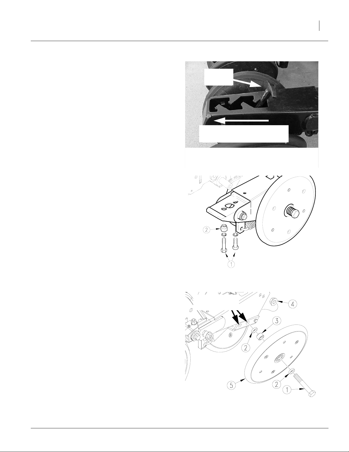
Offset. The closing wheels can be offset to help
preventtrash from plugging the closing wheels.
To offset the closing wheels:
Refer to Figure 27
1. Raisebeanmachineslightly toremoveweight
from closing wheels.
2. Remove5/8-inch bolt (1), spacers (2), pivot
tube (3) and hex flange nut (4) attaching
wheel (5) to press-wheel arm.
3. Move closing wheel (5) to other mounting hole
and reattach with hardware. Torque bolt as recommended, see “Appendix,”page 80.
4/11/2005
mounting hole
locations
Closing Wheel Offset
Figure 27
12347
173-208M
Page 32

2015P and 2515P
30
Closing Disk Option
For proper seed-to-soil contact, the closing disks
must have enough down pressure to close the
seed trench without unnecessary soil
compaction.
Refer to Figure 28
To adjust downpressure on closing disks, ratchet
spring cam to next cam height by turning head of
support bolt (1) clockwise.
Frame Height
Bean machine operating height directly affects
the working range of the row units. Initially adjust
frame height as explained under “Leveling Bean
Machine”, page 18. You can make further adjustments to compensate for field conditions.
Figure 28
Closing Disk and Tube Holes
17720
Refer to Figure 29
NOTE: Jam nut is left-hand threaded.
Make sure upper clevis (2) is in the upper mount
hole. Loosen jam nut (1) to lengthen or shorten
gauge-wheel turnbuckle.
• Lengthening turnbuckles raises bean machine and allows less row unit down float.
• Shortening turnbuckleslowersbean machine
and allows less row unit up float.
Adjust both turnbuckles to the same length and
tighten jam nuts.
After adjusting gauge-wheel turnbuckles, be sure
to level the bean machine with top hitch link.
NOTE:Lowering the bean machine increases the
risk of row unit damage on rocks or obstructions.
Seeding Rate
Adjusting the seeding rate requires the following:
1. adjusting drive speed range sprockets,
Figure 29
Gauge Wheel Turnbuckle
17773
2. adjusting transmission sprockets,
3. preparing seed meters,
4. checking seeding rate.
Before setting the seeding rate, rotate the gauge
wheels. Check that seed meters, seed tubes and
drives are working properly and free from foreign
material.
173-208M
4/11/2005
Page 33

Drive Speed Range Sprockets
Selectthe correct drivespeedrange sprocketsfor
your seed by referring to the Seed Rate Charts
beginning on page 66.
Refer to Figure 30
Loosen idler (1) and remove chain (2). Remove
retaining pins (3) from shafts and install speed
range sprockets as necessary.
NOTE: Make sure the correct sprockets have
been installed in the DRIVER and DRIVEN locations as shown.
Reroute chain over sprockets and idlers as
shown. Move idler into chain so chain has 1/4inch slack in its longest span. Tighten idler and install retaining pins.
Driven
3
2
Adjustments
31
Set the same drive range sprocket combination
on both gauge wheels.
Transmission Sprockets
To change the seeding rate, change the transmission sprocket combination. Refer to the Seed
Rate Charts beginning on page 66.
Refer to Figure 31
Loosen idler plate (1) and remove drive chain (2).
Removelynch pins (3) from shafts and rearrange
drive and driven sprockets as necessary.
Reroute drive chain over sprockets and idlers as
shown. Move idlers into chain so chain has 1/4inch slack in its longest span. Tighten idlers and
install lynch pins.
1
Driver
Figure 30
Drive Speed Range Sprockets Adjustment
Driven
Driver
3
2
3
18277
Set the same transmission sprocket combination
on both gauge wheels.
4/11/2005
1
Figure 31
Transmission Sprockets Adjustment
3
18278
173-208M
Page 34

2015P and 2515P
32
Shutting Off Seed Flow
Refer to Figure 32
Figure 32 shows the sliding seed tubes in the
open position. To shut off seed flow, move tubes
forward.The following instructions explain how to
shut off seed flow to each meter.
Sliding seed
tubes
Shut off
Refer to Figure 33
1. Removethe retaining clipand pullpin. Do not
remove cotter pin.
Refer to Figure 34
2. Movemeter cap to position seed tube over
shut off pad.
3. Place pin in hole of meter cap and install retaining clip.
Figure 32
Sliding Seed Tubes in open position
Slidingseed
tube
Retaining
clip
Figure 33
Sliding
seed tube
18290
Shut off
pad
18302
4. Repeat steps 1 through 3 for each meter.
NOTE: When pin with retaining clip is located in
the slot, sliding seed tube is open. When pin with
retaining clip is located in the hole, sliding seed
tube is closed.
173-208M
Retaining
clip
Figure 34
Figure 1
18303
18303
4/11/2005
Page 35

Cleaning Out Meters
NOTE:Shut off sliding seed tubes before attempting to clean out seed meters.
Refer to Figure 35
For seed meter clean out:
1. Position tarp or buckets under the row unit(s)
whose meter(s) you will be cleaning out.
Retaining clip
Adjustments
33
2. Removeretaining clip and pull pin.
Refer to Figure 36
3. Pull up on meter clean out door to open.
Refer to Figure 37
Clean out door
Meter clean out door
Clean out door
Figure 35
Meter clean out
Figure 36
18261
19190
4. When meter is empty, push meter clean out
door back to its original position to close.
NOTE:You mayneed to shake the clean out door
a little before closing to make sure all seeds fall
out.
5. Replace pin and retaining clip.
4/11/2005
Clean out door
Close and pin clean out door
Figure 1
Figure 37
Meter Clean Out
18293
19192
173-208M
Page 36

2015P and 2515P
34
Changing Seed Meter Wheels
Choose the correct seed meter wheel for the type
ofseed you will beusing. Be sure to usethe same
wheel type on all meters.
Refer to Figure 38
To change seed meter wheels:
1. Shutoff seedflow to metersby movingsliding
seed tubes. For more information see page
32.
Refer to Figure 39
2. Clean out meter. For more information see
page 33.
Sliding seed
tube
Figure 38
Sliding seed tube shut off
18298
Refer to Figure 40
3. Push in spring-loaded wheel retainer and
turn. Pull off wheel retainer and spring.
173-208M
Figure 37
Figure 39
Meter clean out
Meter clean out
Wheel retainer
and spring
Figure 40
Remove wheel retainer and spring
19192
19192
18294
4/11/2005
Page 37
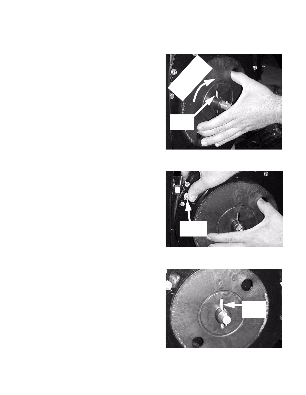
Refer to Figure 41
4. Pull seed meter wheel out about 1/4 inch, or
pastthewheel drivepin, andspin backwardto
clean out seeds from top pockets.
Adjustments
35
5. Removeseed meter wheel.
NOTE: With the seed meter wheel removed, you
may want to check the meter for internal damage
or trash.
Refer to Figure 42
6. Place new wheel on meter wheel shaft and
push meter slide retaining clip forward while
pushing in seed meter wheel.
Spin wheel
backward before
removing
Wheel
drive pin
Remove seed meter wheel
Retaining
clip
Figure 41
18295
Refer to Figure 43
7. Be sure slots in the center of seed meter
wheel are aligned with the wheel drive pin on
the meter shaft.
4/11/2005
Figure 42
Place new seed meter wheel on wheel shaft
18296
Wheel
drive pin
Figure 43
Position seed meter wheel
18299
173-208M
Page 38

2015P and 2515P
36
Refer to Figure 44
8. Reinstallspring and lock wheel knob in place.
Wheel
knob
Refer to Figure 45
9. Close and pin seed meter clean out.
Refer to Figure 46
10. Open sliding seed tubes and pin in place.
Figure 44
Wheel retainer locked in place
Figure 45
Close and pin clean out
19190
19192
173-208M
Figure 46
Open and pin sliding seed tube
18300
4/11/2005
Page 39

Checking Singulated Seeding Rate
The seed charts are based on cleaned and sized
seed. Extreme seed size variations, foreign material and tire pressure will affect the seeding rate.
Check the seed population rate as described
below.
1. Adjust the planting depth to a shallow setting.
2. Plantat the desired planting speed fora short
distance.
3. Using Table 1, determine how many rows
need to be counted.
4. Measurea distance of 17’ 5” in the planted area.
5. Count the number of seeds, in the appropriate number of rows, over the distance measured.
Planted row
spacing
(inches)
15 2 17’ 5”
30 1 17’ 5”
Number of
rows to count
Table 1
Adjustments
Length of row
to measure
37
6. Multiply the number of seeds counted by
1,000. This is the plant population in seeds
per acre.
Example 1:
If you have a 15-inch row spacing bean machine,
according to Table 1, two rows must be counted.
Measure 17’ 5” and count the number of seeds in
two rows. If the number is, for example, 180, multiply 180 by 1,000.
180 x 1,000 = 180,000 seeds per acre.
Example 2:
If you have a 15-inch row spacing bean machine,
butdesire to plant soybeans on 30-inch row spacing, according to Table 1, one row must be
counted. Measure 17’ 5” and count the number of
seeds in one row. If the number is, for example,
180, multiply 180 by 1,000.
180 x 1,000 = 180,000 seeds per acre.
7. Ifthe plantingpopulation is significantly different than desired, make the following checks:
• Double check the transmission and range
sprocket combinations. Refer to the seed
population chart for the seed being planted.
Seed rate charts
Seed rate charts begin on page 66. The charts
givetransmission sprocketcombination and drive
range sprockets for row spacing used, to achieve
the population or pounds per acre desired. The
charts also giveseedspacing for singulated seed.
4/11/2005
• Check the air pressure in the gauge wheel
tires. Refer to “Tire Inflation Chart” on page
81.
• Refer to Troubleshooting on page 45.
Each seed chart has a corresponding page showing the different drive ranges for that seed and a
transmission sprocket reference.
173-208M
Page 40

2015P and 2515P
38
Marker Adjustments
Bleeding Marker Hydraulics
To fold properly, the marker hydraulics must be
free of air.If the markers fold in jerky, uneven motions, follow these steps.
!
CAUTION
You may be injured if hit by a folding or unfolding
marker. Markers may fall quickly and unexpectedly if
the hydraulics fail. Never allow anyone near the bean
machine when folding or unfolding the markers.
!
WARNING
Escaping fluid under pressure can have sufficient pressure to penetrate the skin. Check all hydraulic lines
and fittings before applying pressure. Fluid escaping
froma very small hole can be almost invisible.Use paper or cardboard, not body parts, and wear heavy
gloves to check for suspected leaks. If injured, seek
medical assistance from a doctor that is familiar with
this type of injury. Foreign fluids in the tissue must be
surgically removed within a few hours or gangrene
will result.
Check that tractor hydraulic reservoir is full.
1. Withboth markers lowered into field position,
loosenhydraulic-hose fittingsat rod and base
endsof markercylinders.If applicable,loosen
fittings on back side of sequence valve.
IMPORTANT: Neverbleed an O-ring fitting. Instead, bleed a nearby pipe or JIC fitting.
2. With tractor idling, activate tractor hydraulic
valveuntil oil seeps out around a loosened fitting. Tighten that fitting.
IMPORTANT: JIC fittings do not require high
torque. JIC and O-ring fittings do not require
sealant. Always use liquid pipe sealant when
adding or replacing pipe-thread fittings. To
avoid crac king hydraulic fittings from over
tightening, do not use plastic sealant tape.
3. Reactivate tractor hydraulic valve until oil
seeps out around another loosened fitting.
Tighten that fitting. Repeat process until all
loosened fittings have been bled and tightened.
173-208M
4/11/2005
Page 41
Folding Speed with Needle Valves
Refer to Figure 47
A needle valvecontrols the folding speed of markersthat areplumbed separately.The needlevalve
is near the rod end of the marker cylinder.
With tractor idling at a normal operating speed,
adjust markerfoldingto a safe speed. Turn adjustment knob clockwise to reduce folding speed or
counterclockwise to increase folding speed. Excessivefoldingspeed could damage markersand
void the warranty.
Adjustments
39
Folding Speed with Sequence Valve
Refer to Figure 48
If markers are tied together with an optional sequence valve, adjust folding speed with hex
adjustment screws on the sequence-valve body.
There is one adjustment screw for raising speed
(1) and one forlowering speed (2). Identifyadjustment screws by markings stamped in valve body.
With tractor idling at a normal operating speed,
adjust markerfoldingto a safe speed. Turn adjustmentscrews clockwise to decrease foldingspeed
and counterclockwise to increase folding speed.
Excessive folding speed could damage markers
and void the warranty.
Afteradjustingthefoldingspeed, tighten jam nuts
on hex adjustment screws to hold settings.
Marker Disk Adjustment
!
CAUTION
Marker disks may be sharp. Use caution when making
adjustments in this area.
Figure 47
Needle Valve
Hex adjustment
screws
Figure 48
Speed Adjustment, Sequence Valve
Increase
speed
Decrease
speed
17620
14048
Changing disk angle
Refer to Figure 49
Ifmark leftbymarker disk is not clearly visible,adjust disk angle to make a wider mark. Loosen two
1/2 inch bolts (1) holding disk assembly (2). Rotate disk assembly as desired.
4/11/2005
Figure 49
Disk Angle
17676
173-208M
Page 42

2015P and 2515P
40
Leveling marker disk
Refer to Figure 50
If the marker disk is not square with the ground
when the marker is lowered in the field, or if the
marker arm tends to fold up while lowered in the
field, adjust the marker mount.
To adjust, loosen 1/2-inch bolts (1) and rotate
marker mount (2) until marker disk is square with
the ground (3).
Transport Carrier
Refer to Figure 51
Whenmarker isfolded,the second sectionshould
rest in transport-carrier saddle.
To adjust front-to-rear position of saddle, loosen
1/2-by-6-inch u-bolts (1) that fasten transport-carrier mount onto boxframe.Slide transport-carrier
assembly forward or back as needed.
To adjust height of saddle, loosen 1/2-by-2-inchubolts (2) that hold carrier tube to mounting bracket. Slide carrier tube up or down as needed.
17635
Figure 50
Squaring Disk Marker
173-208M
Figure 51
Adjusting Marker Carrier
15632
4/11/2005
Page 43

Marker Chain (2515P only)
Refer to Figure 52
There are two interrelated adjustments for the
marker chain. Make these adjustments in the following order.
1. Lifting Slack. With marker unfolded, back
full-threaded adjustment bolt (1) down until
head extends as little as possible. Slowly fold
marker while observing disk. If marker disk
slides across ground more than a foot before
chain and linkage lifts it up, the chain is too
long.
Shorten chain one or two links by moving clevis(2). Checkadjustmentby repeatingfolding
process.
If chain is too short when marker is unfolded,
it will prevent end of marker from dropping
into field depressions, causing skips in your
marker line. Correct this condition by lengthening chain one or two links at clevis (2).
2. FoldingSlack.Fold marker.Usefull-threaded
adjustment bolt (1) to take slack out of chain
whilemarkerisfolded.Extend boltuntil thereis
no chain slack. Lock bolt in this position by
tightening nuts (3) on either side of upright
channel (4).
Figure 52
Marker Chain Adjustment
Adjustments
15669
41
4/11/2005
173-208M
Page 44

2015P and 2515P
42
Marker Width
Refer to Figure 53
To adjust marker width, loosen jam nuts (1) and
1/2-inchset screws(2). Movemarkerdisk tube (3)
in or out to get the proper dimension.
Refer to Figure 54
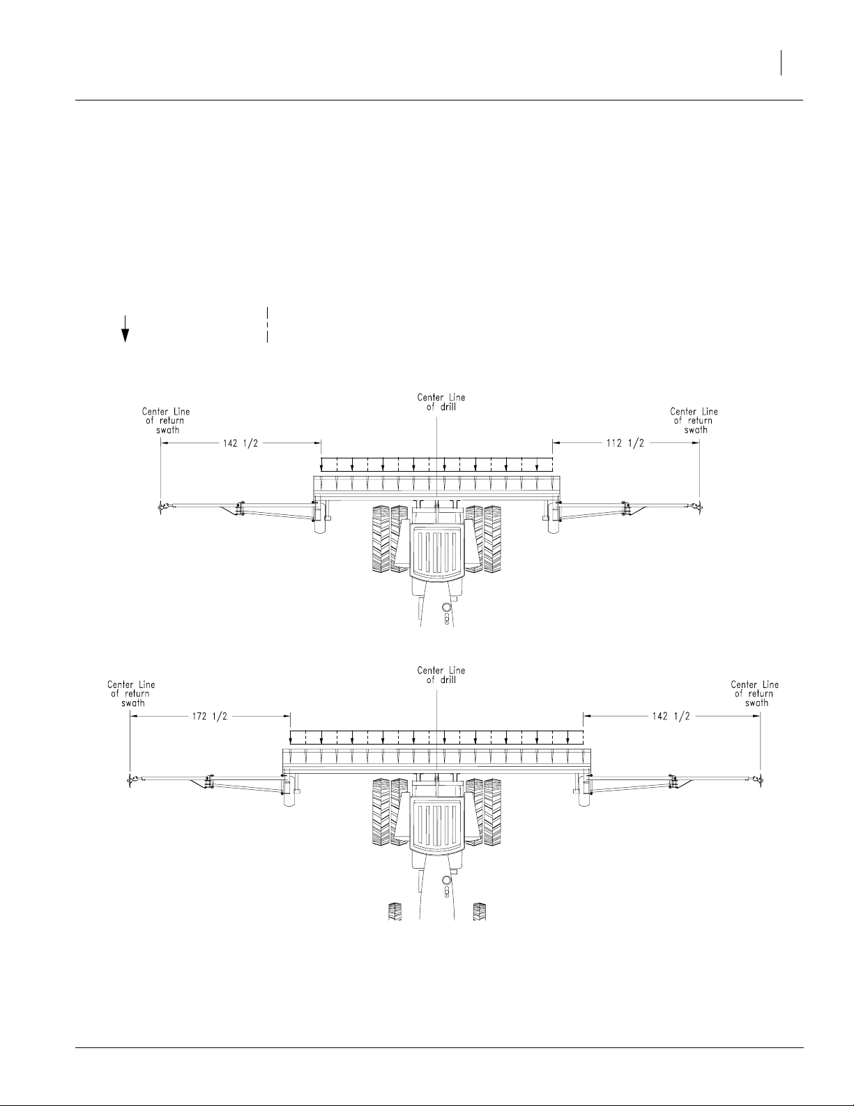
The diagram below shows marker widths for 15inch spacing with all meters open.
To measure for marker width adjustment:
1. Lowerbean machine in the field and drive forward a few feet.
2. Measurefrom themiddle of theoutside rowto
the mark in the ground made by the marker
disk.
NOTE:If planting 30 inch rowspacing byshutting
off meters, markers may need to be readjusted.
Refer to page 43 for more information.
2015P
18304
Figure 53
Marker Width
173-208M
2515P
Figure 54
Marker Width
18530
4/11/2005
Page 45
Refer to Figure 55
A 30 inch row spacing can be achieved by shutting off certain meters.The diagrambelow shows
which rows to shut off, which to leave on and the
marker width to use.
Legend:
= planting rows = non planting rows
Adjustments
43
2015P
2515P
Figure 55
Marker Width
18551
4/11/2005
173-208M
Page 46
2015P and 2515P
44
Seed-Lok Lock Up
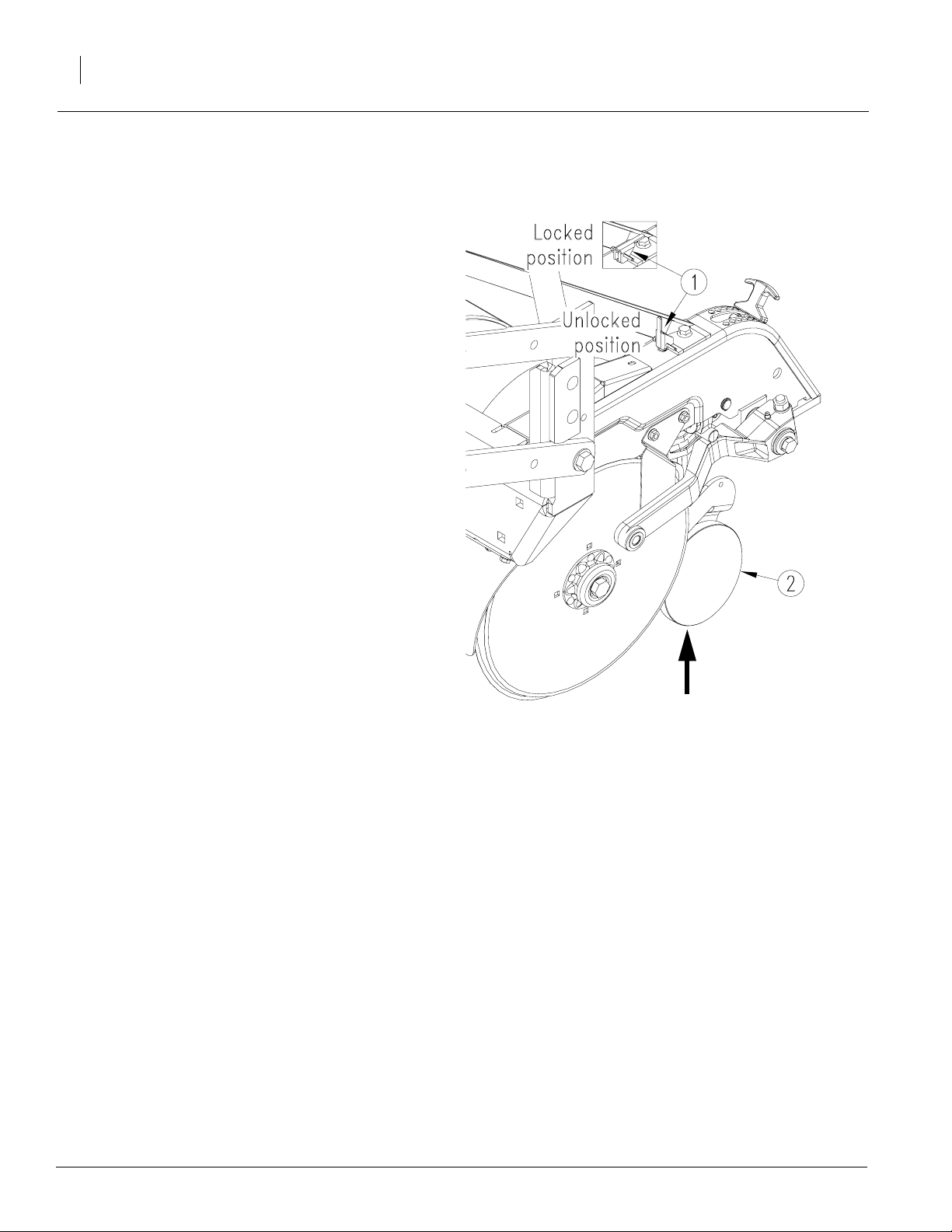
Refer to Figure 56
Optional Seed-Lok firming wheels provide additional seed-to-soil contact. The wheels are spring
loaded and do not require adjusting. In some wet
and stickyconditions the wheels may accumulate
soil.
To lock up the firming wheels in wet conditions,
raise bean machine. Push the lock-up handle (1)
on top of the row-unit body up into the position.
Push up on the firming wheel (2) until the wheel
arm latches up.
To unlock the firming wheels, turn the lock-up
handle back to its 90-degree position.
NOTE:Side gauge wheel is removed in figure 56
for clarity.
Push Seed-Lok
up to lock.
Figure 56
Seed-Lok Lock Up
18454
173-208M
4/11/2005
Page 47

Troubleshooting
Problem Cause Solution
Troubleshooting
45
Planting too much
Planting too little
Incorrect seed rate or sprocket combination.
Wrong seed meter wheel installed. Install correct seed meter wheel.
Actual field size is different. Verify field size.
Excessive overlap.
Irregular shaped field.
Incorrect tire size or air pressure. Correct tire size and air pressure, page
Meter clean out door is open. Close and pin meter clean out door,
Seed meter wheel spring or retaining
cap damaged or missing.
Incorrect seed meter wheel for seed
size.
Seed meter wheel not seated correctly
on meter shaft.
Seed meter wheel damaged or missing. Check seed meter wheel and replace if
Seed meter slide is sticking open. Remove and clean seed meter slide and
Seed meter slide worn. Replace seed meter slide, page 51.
Incorrect seed rate or sprocket combina-
tion.
Check seed rate information beginning
on page 30.
Adjust marker, page 42.
81.
page 33.
Check seed meter wheel spring and
retaining cap, page 34.
Verify seed count on seed bag with seed
meter wheel.
Check installation of seed meter wheel,
page 34.
damaged.
check for wear, page 51.
Check seed rate information beginning
on page 30.
4/11/2005
Excessive field speed. Slow down. Check Seeding Rate Chart
Incorrect seed meter wheel for seed
size.
Incorrect tire size or air pressure. Correct tire size and air pressure, page
Check seed level in seed box. Fill seed box.
Actual field size is different. Verify field size.
Excessive gaps between bean machine
passes.
Not enough talc lubricant Add more talc lubricant, page 22.
Build up of seed treatment in meter. Clean out seed meter, page 33. Add
for correct maximum field speed.
Verify seed count on seed bag with seed
meter wheel.
81.
Adjust marker, page 38.
more talc lubricant.
173-208M
Page 48

2015P and 2515P
46
Problem Cause Solution
Planting too little (cont’ d)
Uneven seed spacing
Seed flow shut off not 100% open and
pinned.
Plugged sliding seed tube. Clean out sliding seed tube.
Plugged row unit seed tube. Lift up bean machine, expose bottom of
Seed meter wheel damaged. Replace seed meter wheel.
Obstruction in meter (foreign material or
uncleaned seed).
Thrown or worn drive chains. Check drive chains.
Worn sprockets and/or chain idlers. Replace sprockets and/or chain idlers,
Excessive field speed. Slow down. Check Seeding Rate Chart
Unclean seed. Use clean seed.
Lack of talc lubricant. Add talc lubricant, page 22.
Build up of seed treatment in meter. Clean out seed meter, page 33. Add
Seed-Lok plugging. Lock up Seed-Lok, page 44.
Opener disks not turning. See “Opener disks not turning freely” in
Check seed flow shut off, page 32.
seed tube and clean out.
Clean seed meter.
page 55.
for correct maximum field speed.
more talc lubricant.
this Troubleshooting chart.
Uneven seed depth
Plugged or damaged opener seed tube. Lift up bean machine, expose bottom of
Worn/rusted sprockets and/or chain
idler.
Seed meter wheel damaged or worn. Check seed meter wheel and replace.
Seed meter slide worn. Replace seed meter slide, page 51.
Plugged sliding seed tube. Clean out sliding seed tube.
Incorrect seed meter wheel for seed
size.
Excessive field speed. Slow down. Check Seeding Rate Chart
Coulter depth adjustment Check adjustment, see page 27.
Planting conditions too wet. Wait until drier weather.
Bean machine frame height incorrect. Check bean machine frame height, page
Bean machine not level front-to-back in
field.
Row unit side depth wheels are set too
deep for soil conditions or coulter depth.
Row unit spring force is set too high. Check row unit adjustments, page 26.
seed tube and clean out.
Check and replace any worn/rusted
sprockets or chain idlers.
Verify seed count on seed bag with seed
meter wheel.
for correct maximum field speed.
30.
Readjust top link to level bean machine.
Check row unit adjustments, page 26.
173-208M
Seed-Lok building up with dirt. Lock up Seed-Lok, page 44.
4/11/2005
Page 49

Problem Cause Solution
Troubleshooting
47
Uneven seed depth (cont’ d)
Opener disks not turning
freely .
Acremeter does not measure
accurately
NOTE:Acremeter is most accu-
rate when seeding back and forth
with markers with few headlands,
curves and pointrows.
Seed bouncing out of furrow. Engage Seed-Lok in dry conditions,
Damaged row unit seed tube. Check disk spreader, page 55.
Partially plugged row unit seed tube. Lift up bean machine, expose bottom of
Row unit plugged with dirt. Clean row unit.
Planting conditions too wet. Wait until drier weather.
Seed-Lok is plugging opener. Lock up Seed-Lok, page 44.
Bean machine frame height incorrect. Check bean machine frame height, page
Bean machine not level front-to-back in
the field.
Opener side depth wheels not adjusted
correctly.
too tight - dragging on blade
too loose - allowing dirt between
blade and wheel
Row unit spring force is set too high. Check row unit adjustments, page 26.
Too much blade-to-blade contact. Take shims under head of bolt and put
Failed disk bearings. Replace disk bearings.
Bent or twisted opener frame. Replace opener frame.
Incorrect tire size or air pressure Correct tire size or air pressure, page 81.
Excessive overlap or gaps between
passes.
Soil conditions. Loose soil and slippage will cause varia-
Check that acremeter is for your width of
bean machine.
page 44.
seed tube and clean out.
30.
Readjust top link to level bean machine.
Check row unit adjustments, page 26.
between opener and disk bearing, see
page 56 for information.
Avoid overlap or gaps. Check marker
adjustment, page 42.
tions in acres registered.
Refer to bean machine parts manual.
4/11/2005
Press wheels not compacting
the soil as desired
Actual field size different. Verify field size.
Too wet or cloddy. Wait until drier weather or rework
Coulter set too shallow. Check coulter adjustment, page 27.
Bean machine not running level front-to-
back in the field.
Row unit spring pressure too high. Reduce row unit spring pressure.
Not enough pressure on press wheels. Check row unit adjustment, page 26.
ground.
Readjust top link to level bean machine.
173-208M
Page 50

2015P and 2515P
48
Problem Cause Solution
Excessive seed cracking
Bean machine boxes do not
empty evenly
Excessive field speed. Slow down. Check Seed Rate Chart for
Unclean seed. Use clean seed.
Incorrect seed meter wheel. Change seed meter wheel, page 34.
Incorrect seed size for seed meter
wheel.
Build up of seed treatment in seed meter
wheel pockets.
Worn or damaged seed meter wheel. Replace seed meter wheel.
Worn or damaged meter slide. Replace meter slide, page 51.
Damaged, old or dry seed. Use clean, new seed.
Right and left hand seed rates are not
set the same.
Tire sizes or tire inflation not equal on
right and left gauge wheels.
Meter(s) are shut off. Open meter(s).
Row unit seed tube plugged. Lift up bean machine, expose bottom of
Sliding seed tube plugged. Clean out sliding seed tube.
Drive chains damaged or missing. Replace drive chains.
Drive torque requirements different on
right and left gauge wheel drives.
correct maximum field speed.
Verify seed count on seed bag with seed
meter wheel.
Clean seed meter wheel. Add more talc
lubricant.
Readjust rates, see Seed Rate Chart.
Correct tire size or tire inflation, page 81.
seed tube and clean out with wire.
Check gauge wheels and tires.
Press wheel or row units plugging
Unequal number of sliding seed tubes in
each box compartment.
Planting around fields vs. back-andforth.
Rough field conditions maymove seed in
the box.
Planting conditions too wet. Wait until drier weather.
Bean machine not running level front-to-
back in the field.
Bean machine frame height incorrect. Adjust bean machine frame height, page
Row unit set too deep. Readjust, page 26.
Row unit spring force is set too high. Check row unit adjustments, page 26.
Row unit 1 x 12 press wheel stagger
adjustment not correct.
Backed up with row units in the ground Clean out and check for damage.
Failed disk bearings Replace disk bearings.
Disk blades worn. Adjust or replace disk blades, page 56.
Correct planting operation.
Readjust top link to level bean machine.
30.
Correct press wheel stagger.
173-208M
4/11/2005
Page 51

Problem Cause Solution
Troubleshooting
49
Bean machine is not pulling
level front-to-back
Hydraulic marker functioning
improperly
Marker disk does not mark
Chain
Row unit side depth wheels not adjusted
correctly.
Scraper worn or damaged. Replace scraper.
Incorrect top link adjustment. Readjust top hitch link to level bean
Air or oil leaks in hose fittings or connections.
Low tractor hydraulic oil level. Check tractor hydraulic oil level.
Loose or missing bolts or fasteners. Check all bolts and fasteners.
Needle valve plugged. Open needle valve,cycle markers slowly
Needle valve(s) in sequence valve
plugged.
Marker folding linkage does not have
enough slack to allow marker disk to
drop into field depressions.
Disk orientation not correct for field conditions.
Debris in retainer clip Be sure retainer clip is facing opposite
Readjust, page 26.
machine.
Check all hose fittings and connections
for air or oil leaks.
and reset needle valve, refer to page 39.
Open needle valves, cycle markers
slowly and reset needle valves, refer to
page 39.
Maximum down float should be limited
by the slot at the rod end of the marker
cylinder - not by the chain, refer to page
39.
Reverse marker disk to pull or throw dirt.
way of chain travel
4/11/2005
173-208M
Page 52

2015P and 2515P
50
Maintenance and Lubrication
Maintenance
Proper servicing and maintenance is the key to
long implement life. With careful and systematic
inspection, you can avoid costly maintenance,
downtime and repair.
Alwaysturn off and removethe tractor keybefore
making any adjustments or performing any
maintenance.
!
WARNING
You may be severelyinjured or killed by being crushed
under the falling implement. Always have transport
locks in place and frame sufficiently blocked up when
working on implement.
OFF
!
WARNING
Escaping fluid under pressure can have sufficient pressure to penetrate the skin. Check all hydraulic lines
and fittings before applying pressure. Fluid escaping
froma very small hole can be almost invisible.Use paper or cardboard, not body parts, and wear heavy
gloves to check for suspected leaks. If injured, seek
medical assistance from a doctor that is familiar with
this type of injury. Foreign fluids in the tissue must be
surgically removed within a few hours or gangrene
will result.
1. After using bean machine for several hours,
check all bolts to be sure they are tight.
2. Lubricate areas listed under “Lubrication”,
page 58.
3. Adjust idlers to remove excess slack from
chains. Clean and use chain lube on all roller
chains as needed.
4. Inflate tires as specified on “Tire Inflation
Chart”, page 81.
5. Replace any worn, damaged or illegible safety decals. Order new decals from your Great
Plains dealer. Refer to “Safety Decals”, page
7.
173-208M
4/11/2005
Page 53

Meter Maintenance
Meter Slide Maintenance
Refer to Figure 57
Maintenance and Lubrication
51
Forproperseeding operation,seasonallyor when
changing crops,checkmeter slide for wear.If you
have a noticeable increase in seeding rate you
may need to replace the meter slide.
1. If seed box is not empty,shut off sliding seed
tubes.
Refer to Figure 58
2. Clean out seed meter.
Sliding seed
tube
Figure 57
Sliding seed tube shut off
18298
Refer to Figure 59
3. Removewheel retainer and spring. Refer to
page 34 for more information.
4. Pull seed meter wheel out about 1/4 inch, or
pastthewheel drivepin, andspin backwardto
clean out seeds from top pockets.
5. Removethe seed meter wheel.
Meter slide retaining clip
Spin wheel
backward before
removing
Wheel
drive pin
Remove seed meter wheel
Figure 58
Figure 59
19190
18295
4/11/2005
173-208M
Page 54

2015P and 2515P
52
Refer to Figure 60
6. Check for excess wear on meter slide (1).
Slight wear at the top corner is normal.
7. If slide is not excessivelyworn, stop here. If it
is, continue with the following steps to replace.
Refer to Figure 61
8. Removeretaining clip and pin from meter.
NOTE: Meter slide is spring loaded and the two
meterslidesprings will bereleasedwhenyou pull
the pin. Use care not to lose pins and springs.
9. Check removed pin for wear and replace if
worn.
Figure 60
Meter slide location
Retaining
clip
Figure 61
Meter slide retaining clip
18269
Refer to Figure 62
10. Remove meter slide (1) with springs (2).
11. Place springs in new meter slide andinstallin
meter.
12. Reinstall seed meter wheel.
173-208M
Figure 62
Meter slide and springs
18269
4/11/2005
Page 55

Refer to Figure 63
13. Close and pin meter clean out.
Maintenance and Lubrication
53
Refer to Figure 64
14. Open and pin sliding seed tube.
Chain Tension
The seed meter drive has a spring-loaded idler
which requires no adjusting. However, chain
stretch may make it necessary to shorten the
chain.
Refer to Figure 65
Forbest chain tension the recommended vertical
distance between chain idlers should be not less
than 1/4 inch and not more than 3/4 inch. This
measurement should be taken with opener arms
horizontal.
Refer to Figure 66
Figure 63
Close and pin meter clean out
Figure 64
Open and pin sliding seed tube
rear idler
front idler
Arms
horizontal
Figure 65
Seed Meter Chain Idlers
4/11/2005
NOTE: The front idler should be below the rear
idler.Be sure chain is installed with the chain connector link retainer towards the centerline of the
opener and the clip opening (split end) faces the
opposite way of the chain travel.
Figure 66
Connecting link
173-208M
Page 56
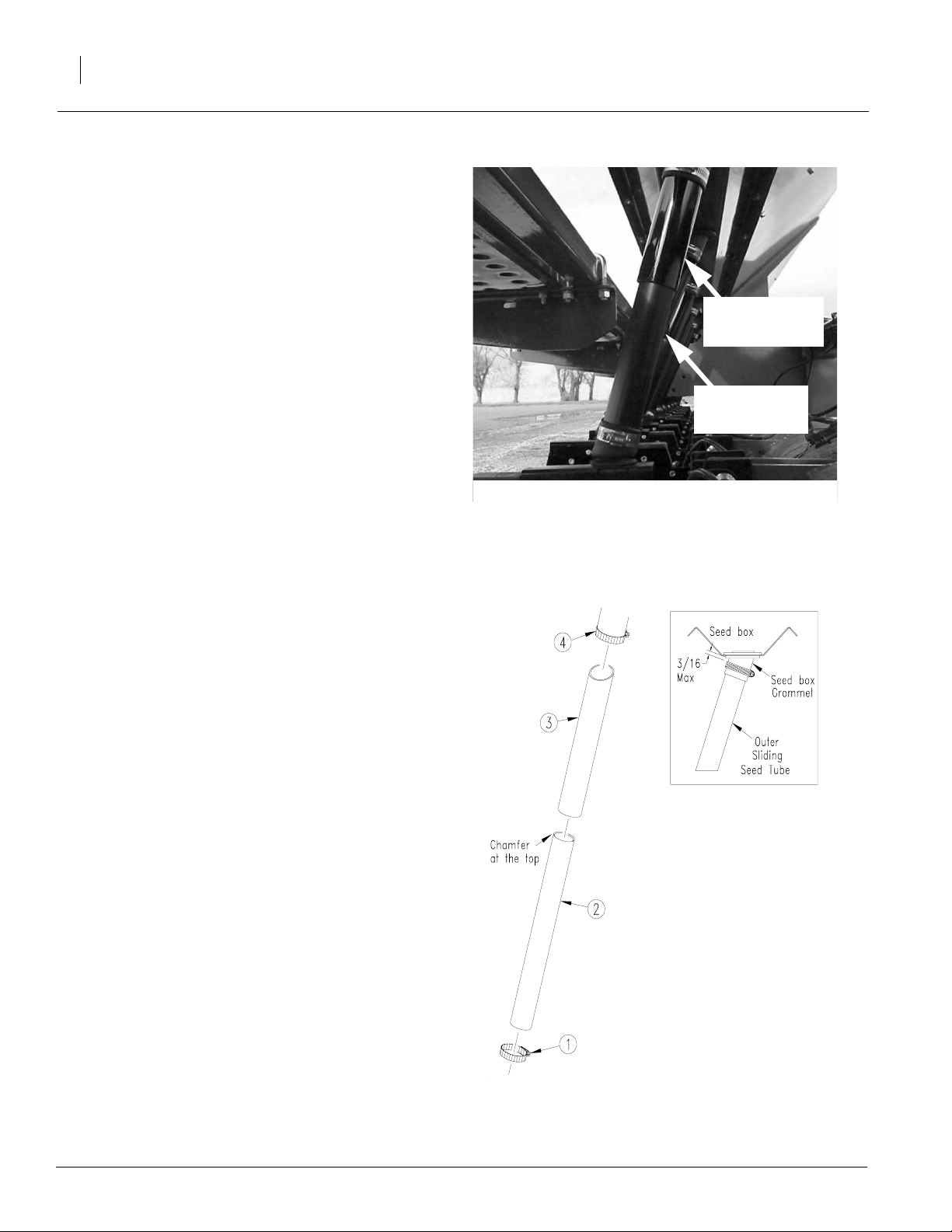
2015P and 2515P
54
Inner Sliding Seed Tube Replacement
Clean inner and outer sliding seed tubes if they
will not slide. Replace inner sliding seed tube if
you see any visible cracks or large burrs.
Refer to Figure 67
To replace inner sliding seed tube follow these
steps:
1. Make sure seed box is empty.
2. Loosen bottom clamp (1).
3. Pull inner sliding seed tube (2) out of seed
meter grommet and pull down out of outer
sliding seed tube (3).
4. Inspect outer sliding seed tube for wear and
replace if necessary.
5. Placenewinner slidingseed tubeinside outer
sliding seed tube. Make sure the chamfer on
the inside of the tube is up as shown.
6. Fit inner sliding seed tube into seed meter
grommet and tighten clamp.
Outer Sliding Seed Tube Replacement
Replace outer sliding seed tube if you see excessive wear on the inside of the tube.
Refer to Figure 68
To replace outer sliding seed tube follow these
steps:
Figure 67
Sliding seed tubes
Outer sliding
seed tube
Inner sliding
seed tube
18451
1. Make sure seed box is empty.
2. Loosen bottom clamp (1).
3. Pull inner sliding seed tube (2) out of seed
meter grommet and pull down out of outer
sliding seed tube (3).
4. Loosen top clamp (4) and pull outer sliding
seed tube from seed box grommet.
5. Fit new outer sliding seed tube into seed box
grommet. Inside the seed box the distance
from the top of the seed tube to the top of the
grommet should be between 1/4 inch to 3/8
inch, see insert in Figure 65. Tighten clamp
(4).
6. Replace inner sliding seed tube inside outer
sliding seed tube as shown, fit into seed
meter grommet and tighten clamp (1).
173-208M
Figure 68
Sliding Seed Tube Replacement
18274
4/11/2005
Page 57

Grommet Maintenance
Periodically check seed meter and seed box
grommets forweathering or cracking and replace
as necessary. Check sliding seed tubes at this
time to make sure they slide freely.
Drive System
Refer to Figure 69
Maintenance and Lubrication
55
Forproperoperationand topreventdowntimeand
repair,keepdrivechains properly adjusted and lubricated. Regularly check drive chains for excess
slack and wear.Adjust idlers to remove any excess slack from chains.
NOTE: Be sure chain is installed with the chain
connectorlink retainer towards the centerline and
the clip opening (split end) facing the opposite
way of the chain travel. See figure 66 page 53.
Row Unit Disk Spreaders and Scrapers
NOTE:It is normal forthe blade spreader to have
some looseness in the holder and between the
blades.Some looseness is required forproper operation.
Refer to Figure 70
1. Removeside gauge wheels from arms to access opener disks and scrapers.
2. Withtheunit raised,check theblade spreader
(1) for wear.Replace spreader if it is 1/2 inches wide or narrower.Toreplace, removedisk
blade(3). Driveout the roll pins (2)and install
a new spreader.
18266
18265
Figure 69
Drive Chains and Idlers
3. When reinstalling disk blades, put two shims
(4) between bearing and shank on each
blade. Tighten bolts.
NOTE: You may need fewerwashers on worn
disks.
4. Check that outside disk scrapers (5) are
formed to disk blades to help remove any
mud. Bend and twist scrapers to fit blades as
necessary. After every 200 acres of bean machine operation, check outside scrapers for
properadjustment andwear.Replaceoutside
scrapers as necessary.
4/11/2005
Figure 70
Disk Spreader and Scraper
17766
173-208M
Page 58
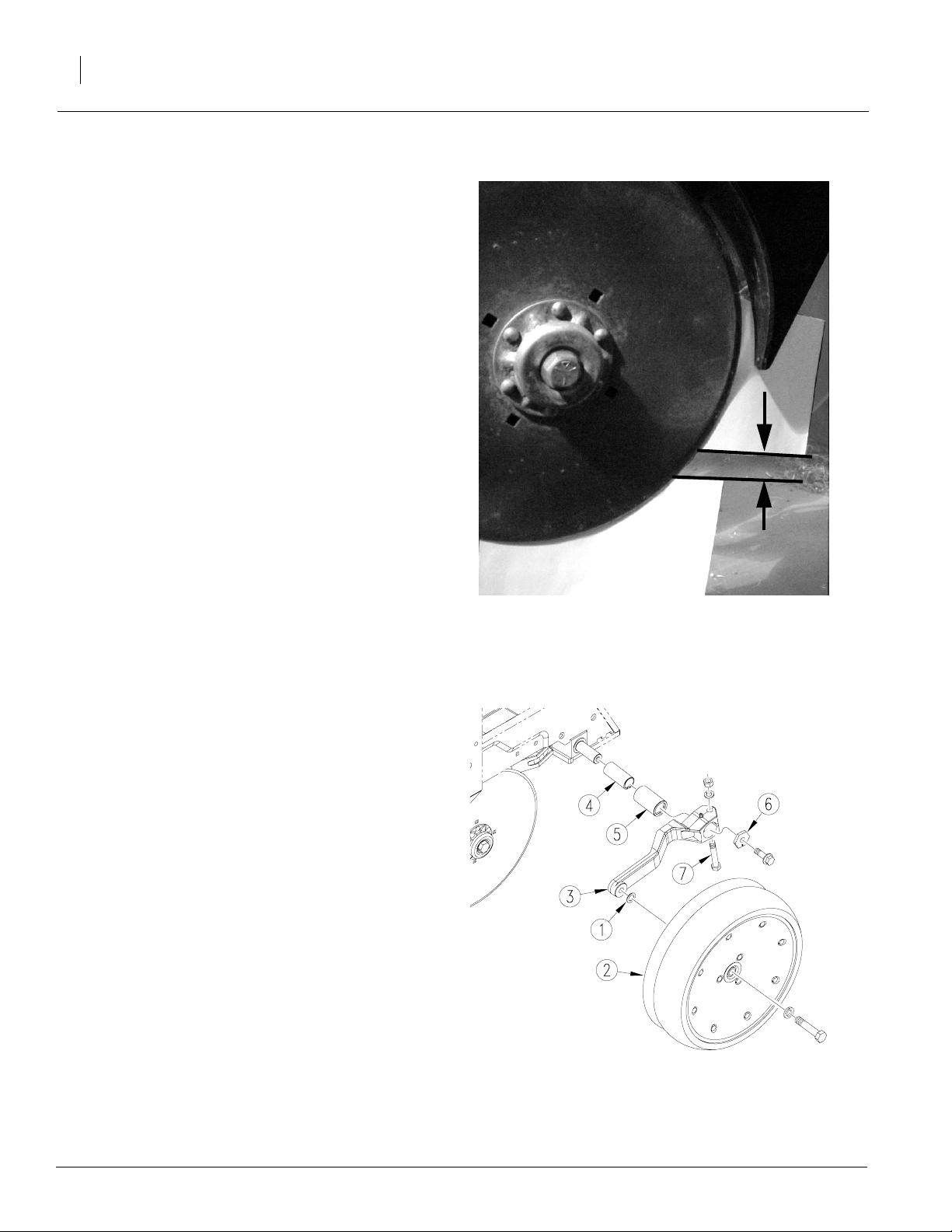
2015P and 2515P
56
Row Unit Disks
1. Removeside gauge wheels from arms to access row unit disks.
1. Check the disk blades for wear. To maintain
proper planting depth, replace if worn to a diameter of 14 1/2 inches or less.
Refer to Figure 71
2. Check contact point between disk blades.
Place a piece of paper in top gap between
disks blades. Bring paper down until it stops.
In lower gap place another piece of paper.
Bring paper up until it stops. Measure the distance between two pieces of paper. The distance must be between 1/2 and 1 3/4 inches.
Add or remove shims as needed to get the
correct contact point.
Row Unit Side Wheels
Refer to Figure 72
1. Lift opener side wheel off the ground. Move
tire in and out to check forend play. Check for
roughness in bearing by rotating wheel. If the
bearings are rough, inspect and replace if
necessary.
1. Checkfor the correct number of shims (1) betweenthe sidegauge wheel(2) andthe wheel
arm (3). There must be at least one shim between the wheel bearing and arm. When installed, the wheel should turn freely and not
hit the arm at the curve. Do not add any more
shims than necessary.
2. Disassembleside-gauge-wheel arm fromrow
unit. Removebushing (4) from sleeve(5) and
check bushing for wear. Replace bushing if
necessary.
3. When reinstalling side gauge wheels, align
tab on hex adjustment (6) with notch in bushing. Replace bolt and tighten.
4. To preventpluggingloosen clamp bolt (7) and
slide arm inward to take up gap between side
wheel and disk blade.
5. Adjust side gauge wheels. Refer to “Adjustments,” page 28.
1/2 inch to
1 3/4 inches
Figure 71
Opener disks contact point
Figure 72
Opener Side Wheel
18412
18452
173-208M
4/11/2005
Page 59

Marker Maintenance
Refer to Figure 73
Themarkerarmis attached to marker body with a
3/8-inch, grade 2, shear bolt. If this shear bolt
breaks, replace it with a grade 2 bolt.
NOTE: Failure to replace the shear bolt with a
grade 2 bolt can cause marker damage.
Ifgrease-seal capformarker-disk-hubbearings is
damagedor missing, disassembleand clean hub.
Repack with grease and install a new seal or
grease cap.
Storage
Store the 3-PointPrecision Bean Machine where
children do not play. If possible, store the 3-Point
Precision Bean Machine inside for longer life.
Maintenance and Lubrication
Figure 73
Marker Shear Bolt
17621
57
1. Unload seed box:
• Place tarp under bean machine or a bucket
under each seed meter.
• Use a large bucket to empty box as much as
possible. Make sure sliding seed tubes are in
theopen position. Openseed meter cleanout
to empty seed out of sliding seed tube and
meter.
2. Thoroughly clean seed and seed-treatment
residue from boxes and seed meters.
3. Removeseed meter wheels. Store flat and
out of the weather.
4. Removeany dirt and debris that can hold
moisture and cause corrosion.
5. Lubricate and adjust all roller chains.
6. Lubricate areas noted under “Lubrication”,
page 58.
7. Inspect bean machine for worn or damaged
parts. Makerepairs and serviceduring theoff
season.
8. Usespray paint to coverscratches, chips and
worn areas on the bean machine to protect
the metal.
9. Coverwith a tarp if stored outside.
4/11/2005
173-208M
Page 60
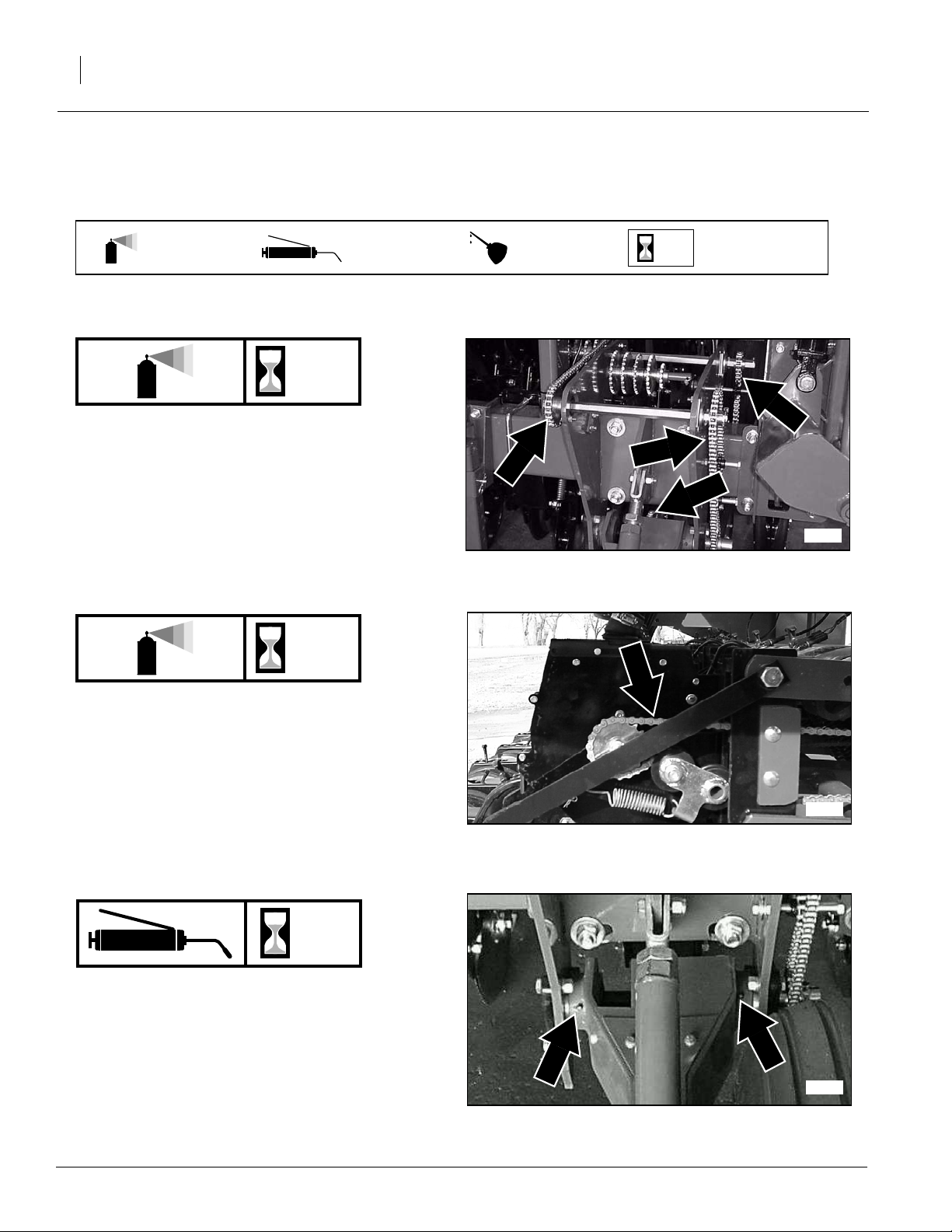
2015P and 2515P
58
Lubrication
Multipurpose
spray lube
Drive Chains
Type of Lubrication: Chain Lube
Quantity = Coat thoroughly
As
Required
As
Required
Multipurpose
grease lube
Multipurpose
oil lube
50
Intervals at which
lubrication is required
18265
Drive Chains
Use care not to spray inside of meter.
Type of Lubrication: Chain Lube
Quantity = Coat thoroughly
15
Gauge Wheel Arm Pivots
Zerks on both gauge-wheel arms
Type of Lubrication: Grease
Quantity = Until grease emerges
18286
18267
173-208M
4/11/2005
Page 61
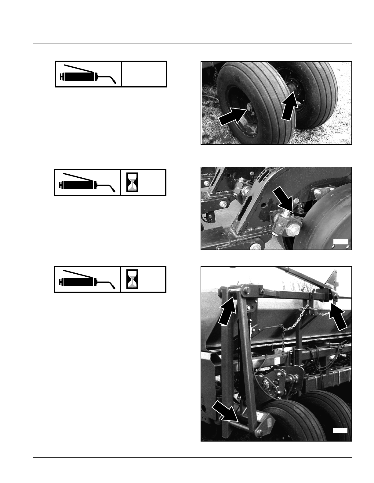
Seasonally
Wheel Bearings
Type of Lubrication: Grease
Quantity = Repack
6
Maintenance and Lubrication
59
17788
Side Wheel Arm, Row Unit
Zerks on both side-wheel arms; two zerks on
each row unit.
Type of Lubrication: Grease
Quantity = Until grease emerges
25
Marker Hinge Points
Type of Lubrication: Grease
Quantity = Until grease emerges
18453
4/11/2005
17784
173-208M
Page 62

2015P and 2515P
60
Marker Disk Bearings
Type of Lubrication: Grease
Quantity = Repack
Seasonally
17784
10
Lift Assist Arm Pivots
Two zerks per arm; four zerks total
Type of Lubrication: Grease
Quantity = About five pumps
10
Lift Assist Castors
One zerk per arm; two zerks total
1827517789
Type of Lubrication: Grease
Quantity = Until grease is visible
173-208M
1827517789
4/11/2005
Page 63
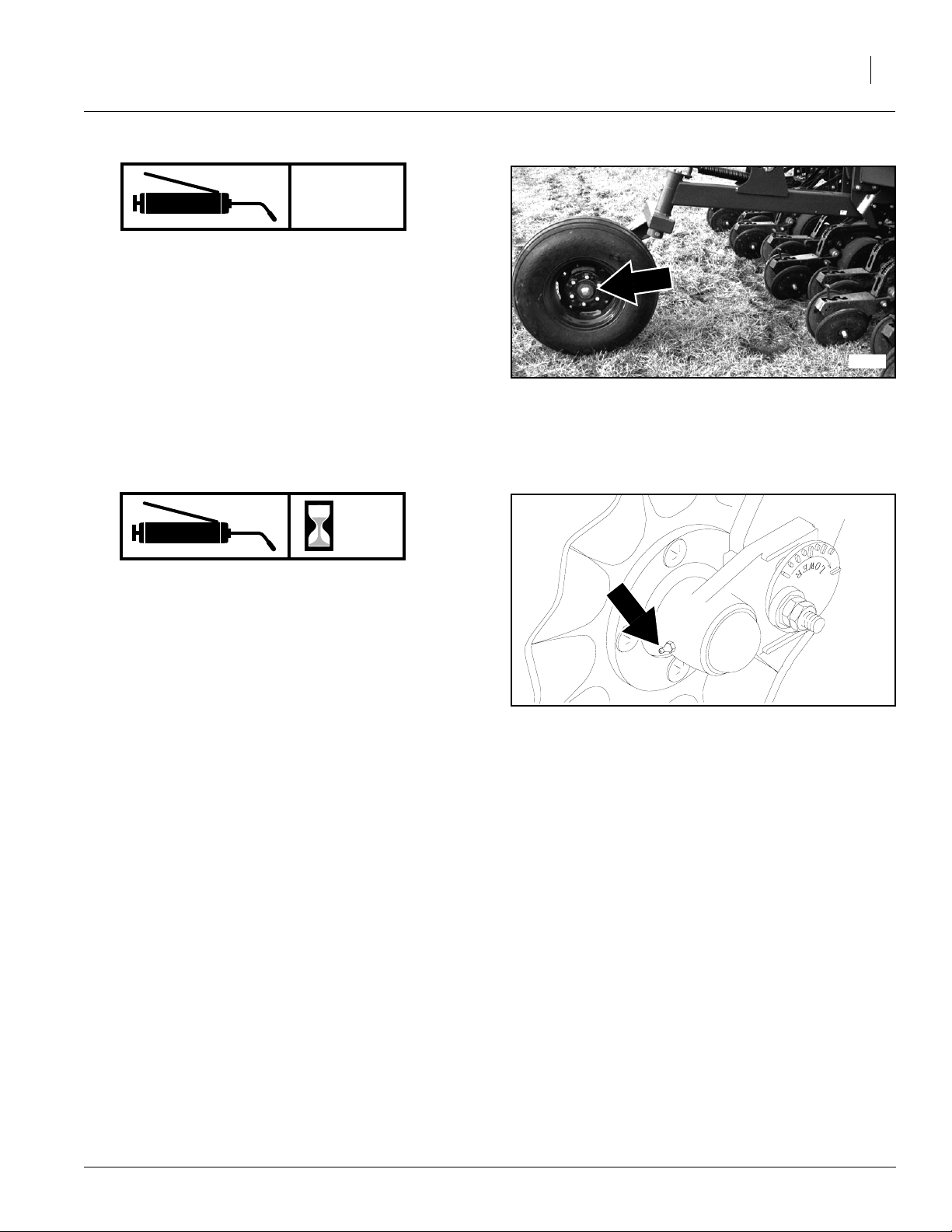
Seasonally
Lift Assist Wheel Bearings
Type of Lubrication: Grease
Quantity = Repack
Maintenance and Lubrication
61
18275
Unit-Mounted Coulter
Type of Lubrication: Grease
Quantity = Until resistance is felt
20
17789
4/11/2005
173-208M
Page 64

2015P and 2515P
62
Options
Markers
Hydraulic markers havea cast hub,tapered roller
bearings and a bolt-on blade to leave a mark for
you to follow on the next field pass. Each marker
requires a hydraulic circuit for operation. A sequence valve is available so markers can be
operated on the same hydraulic circuit.
Formore information on the markers, referto “Operating Instructions,”page 20, and “Maintenance
and Lubrication,” page 50.
To order lift assist, contact your Great Plains
dealer.
Marker Packages Part Number
20’ Bean Machine Dual Marker 113-682A
25’ Bean Machine Dual Marker 113-683A
Sequence Valv e 113-466A
Lift Assist
The optional lift assist is availablefor smaller tractors to help raise the bean machine for field turns
and transport.
For more information on the lift assist, refer to
“Preparation and Setup,” beginning on page 15,
“Operating Instructions,”page 20, and “Maintenance and Lubrication,”page 50.
To order lift assist, contact your Great Plains
dealer.
18461
173-208M
Lift Assist Package Part Number
Lift Assist 124-034A
18529
4/11/2005
Page 65

Spring Pac ka ges
Differentspring packages are availabletoprovide
more down or less pressure on the row unit. The
heavy-duty package provides from 360 to 530
poundsof downpressure atthe openerdisks. The
medium-duty package provides from 260 to 350
pounds of down pressure at the opener disks.
For adjustment information on the spring packages, refer to “Adjustments,” page 26.
To order a spring package, contact your Great
Plains dealer.
Spring Packages Part Number
Heavy Duty Springs 173-150S
Medium Duty Springs 406-006S
Options
63
Coulter
The optional conservation coulters mount on the
rowunits and till a strip for the opener disks in noor minimum till conditions
Forinformationonhowtoadjust thecoulters,refer
to “Adjustments,”page 27. For lubrication information, refer to “Maintenance and Lubrication,”
page 61.
To order coulters, contact your Great Plains
dealer.
Coulter Packages Part Number
Conservation Coulter Fluted 204-416A
Conservation Coulter 3/4 Wavy 204-338A
Conservation Coulter T urbo 204-391A
17729
12204
4/11/2005
173-208M
Page 66

2015P and 2515P
64
Seed-Lok® Firming Wheels
The optional spring-loaded Seed-Lok firming
wheelpressesseed directly into the bottom of the
seed bed. The Seed-Lok option provides more
evenemergence since seeds are planted and
firmed at the same depth.
To order Seed-Lok firming wheels, contact your
Great Plains dealer.
Seed-Lok Packages Part Number
Seed Lok 98 Row Unit 404-093K
15202
DICKEY-john® Monitor
The DICKEY-john®Monitor option is a micro-processor based monitoring system. If seed is not
going to the ground, the monitor will sound and indicate which meter has stopped planting. The
system also provides information for seed spacing, seed population, area, ground speed and the
projected area/hr.
15848
173-208M
4/11/2005
Page 67

Specifications and Capacities
Row Spacing, Inches
Rows Per bean machine
Weight, Pounds
Working Width
Transport Width
Height
Seedbox Capacity
Gauge Wheel Tires
Tractor Requirements
* with markers and without lift assist
Specifications and Capacities
2015P 2515P
15 15
16 20
7200 * 8940 *
20 feet 25 feet
20 feet 7 inches 25 feet 1 inch
5 feet 11 inches 5 feet 11 inches
48 bushels 57.6 bushels
11L x 15, 8 ply 11L x 15, 8 ply
Category II, III, III-N or IV-N Category III or IV-N;200 hp
65
4/11/2005
173-208M
Page 68

2015P and 2515P
66
2015P Corn 28 Cell Wheel (Singulating)
Wheel P/N’s
403-083D (round corn 1400-1900 krl/lb)
403-096D (round corn 1700-2200 krl/lb)
403-086D (flat corn 1500-1675 krl/lb)
403-088D (flat corn 1625-1800 krl/lb)
Seed Rate Charts
1400-1900 krl/lb.
Talc required Range Sprockets
Transmission
Sprockets
Driver Driven (seeds/acre) (inches) (mph)
17 28 13,850 30.2 8
17 27 14,363 29.1 8
17 26 14,915 28.0 8
19 28 15,479 27.0 8
17 25 15,512 27.0 8
19 27 16,053 26.1 8
17 24 16,158 25.9 8
19 26 16,670 25.1 8
17 23 16,861 24.8 8
19 25 17,337 24.1 8
19 24 18,059 23.2 8
23 28 18,738 22.3 8
19 23 18,844 22.2 8
23 27 19,432 21.5 8
24 28 19,553 21.4 8
23 26 20,179 20.7 8
24 27 20,277 20.6 8
25 28 20,367 20.5 8
17 19 20,410 20.5 8
23 25 20,987 19.9 8
24 26 21,057 19.9 8
25 27 21,122 19.8 8
26 28 21,182 19.7 8
23 24 21,861
24 25 21,899 19.1 8
25 26 21,934 19.1 8
26 27 21,967 19.0 8
27 28 21,997 19.0 8
23 23 22,812 18.3 8
28 27 23,656 17.7 8
27 26 23,689 17.7 8
26 25 23,724 17.6 8
25 24 23,762 17.6 8
24 23 23,803 17.6 8
28 26 24,566 17.0 8
27 25 24,636 17.0 8
26 24 24,713 16.9 8
25 23 24,795
19 17 25,495 16.4 8
28 25 25,549 16.4 8
27 24 25,663 16.3 8
26 23 25,787 16.2 8
28 24 26,613 15.7 8
27 23 26,779 15.6 8
23 19 27,614 15.1 8
28 23 27,771 15.1 7
24 19 28,815 14.5 7
25 19 30,015
23 17 30,863 13.5 7
26 19 31,216 13.4 7
24 17 32,205 13.0 6
27 19 32,416
25 17 33,546 12.5 6
28 19 33,617 12.4 6
26 17 34,888 12.0 6
27 17 36,230 11.5 6
28 17 37,572 11.1 5
Seed
Population
15” Row Spacing
Driver = 15
Driven = 30
Seed
Spacing
19.1 8
16.9 8
13.9 7
12.9 6
Max Plant
speed
173-208M
4/11/2005
Page 69

Specifications and Capacities
2015P Corn 56 Cell Wheel (Singulating)
Wheel P/N 403-084D (round corn 1400-1900 krl/bl.)
67
1400-1900 kernels/pound
Talc required Range Sprockets
Transmission
Sprockets
Driver Driven (seeds/acre) (inches) (mph)
17 28 13,850 15.1 8
17 27 14,363 14.6 8
17 26 14,915 14.0 8
19 28 15,479 13.5 8
17 25 15,512 13.5 8
19 27 16,053 13.0 8
17 24 16,158 12.9 8
19 26 16,670 12.5 8
17 23 16,861 12.4 8
19 25 17,337 12.1 8
19 24 18,059 11.6 8
23 28 18,738 11.2 8
19 23 18,844 11.1 8
23 27 19,432 10.8 8
24 28 19,553 10.7 8
23 26 20,179 10.4 8
24 27 20,277 10.3 8
25 28 20,367 10.3 8
17 19 20,410 10.2 8
23 25 20,987 10.0 8
24 26 21,057 9.9 8
25 27 21,122 9.9 8
26 28 21,182 9.9 8
23 24 21,861 9.6 8
24 25 21,899 9.5 8
25 26 21,934 9.5 8
26 27 21,967 9.5 8
27 28 21,997 9.5 8
23 23 22,812 9.2 8
28 27 23,656 8.8 8
27 26 23,689 8.8 8
26 25 23,724 8.8 8
25 24 23,762 8.8 8
24 23 23,803 8.8 8
28 26 24,566 8.5 8
27 25 24,636 8.5 8
26 24 24,713 8.5 8
25 23 24,795 8.4 8
19 17 25,495 8.2 8
28 25 25,549 8.2 8
27 24 25,663 8.1 8
26 23 25,787 8.1 8
28 24 26,613 7.9 8
27 23 26,779 7.8 8
23 19 27,614 7.6 8
28 23 27,771 7.5 8
24 19 28,815 7.3 8
25 19 30,015 7.0 7
23 17 30,863 6.8 7
26 19 31,216 6.7 7
24 17 32,205 6.5 7
27 19 32,416 6.5 7
25 17 33,546 6.2 7
28 19 33,617 6.2 7
26 17 34,888 6.0 6
27 17 36,230 5.8 6
28 17 37,572 5.6 6
Seed
Population
30” Row Spacing
Driver = 15
Driven = 30
Seed
Spacing
Max Plant
speed
4/11/2005
173-208M
Page 70

2015P and 2515P
68
2015P Corn 42 Cell Wheel (Singulating)
Wheel P/N 403-097D (round corn 1400-1700 krl/lb.)
1400-1700 krl/lb.
Talc required Range Sprockets
Transmission
Sprockets
Driver Driven (seeds/acre) (inches) (mph)
17 28 13,850 15.1 8
17 27 14,363 14.6 8
17 26 14,915 14.0 8
19 28 15,479 13.5 8
17 25 15,512 13.5 8
19 27 16,053 13.0 8
17 24 16,158 12.9 8
19 26 16,670 12.5 8
17 23 16,861 12.4 8
19 25 17,337 12.1 8
19 24 18,059 11.6 8
23 28 18,738 11.2 8
19 23 18,844 11.1 8
23 27 19,432 10.8 8
24 28 19,553 10.7 8
23 26 20,179 10.4 8
24 27 20,277 10.3 8
25 28 20,367 10.3 8
17 19 20,410 10.2 8
23 25 20,987 10.0 8
24 26 21,057 9.9 8
25 27 21,122 9.9 8
26 28 21,182 9.9 8
23 24 21,861
24 25 21,899 9.5 8
25 26 21,934 9.5 8
26 27 21,967 9.5 8
27 28 21,997 9.5 8
23 23 22,812 9.2 7
28 27 23,656 8.8 7
27 26 23,689 8.8 7
26 25 23,724 8.8 7
25 24 23,762 8.8 7
24 23 23,803 8.8 7
28 26 24,566 8.5 7
27 25 24,636 8.5 7
26 24 24,713 8.5 7
25 23 24,795
19 17 25,495 8.2 7
28 25 25,549 8.2 7
27 24 25,663 8.1 7
26 23 25,787 8.1 6
28 24 26,613 7.9 6
27 23 26,779 7.8 6
23 19 27,614 7.6 6
28 23 27,771 7.5 6
24 19 28,815 7.3 6
25 19 30,015 7.0 5
23 17 30,863 6.8 5
26 19 31,216 6.7 5
24 17 32,205 6.5 5
27 19 32,416
25 17 33,546 6.2 5
28 19 33,617 6.2 5
26 17 34,888 6.0 5
27 17 36,230 5.8 4
28 17 37,572 5.6 4
Seed
Population
30” Row Spacing
Driver = 20
Driven = 30
Seed
Spacing
Max Plant
speed
9.6 8
8.4 7
6.5 5
173-208M
4/11/2005
Page 71

Specifications and Capacities
2515P Corn 28 Cell Wheel (Singulating)
Wheel P/N’s
69
403-083D (round corn 1400-1900 krl/lb)
403-096D (round corn 1700-2200 krl/lb)
Rd corn 1400-2200 krl/lb.
Flat corn 1500-1800 krl/lb.
Talc Required
Transmission
Sprockets
Driver Driven (seeds/acre) (inches) (mph)
17 28 13,868 30.2 8
17 27 14,381 29.1 8
17 26 14,934 28.0 8
19 28 15,499 27.0 8
17 25 15,532 26.9 8
19 27 16,073 26.0 8
17 24 16,179 25.8 8
19 26 16,691 25.1 8
17 23 16,882 24.8 8
19 25 17,359 24.1 8
19 24 18,082 23.1 8
23 28 18,762 22.3 8
19 23 18,868 22.2 8
23 27 19,457 21.5 8
24 28 19,578 21.4 8
23 26 20,205 20.7 8
24 27 20,303 20.6 8
25 28 20,393 20.5 8
17 19 20,436 20.5 8
23 25 21,013 19.9 8
24 26 21,084 19.8 8
25 27 21,149 19.8 8
26 28 21,209 19.7 8
23 24 21,889 19.1 8
24 25 21,927 19.1 8
25 26 21,962 19.0 8
26 27 21,995 19.0 8
27 28 22,025 19.0 8
23 23 22,841 18.3 8
28 27 23,687 17.7 8
27 26 23,719 17.6 8
26 25 23,754 17.6 8
25 24 23,792 17.6 8
24 23 23,834 17.5 8
28 26 24,598 17.0 8
27 25 24,668 17.0 8
26 24 24,744 16.9 8
25 23 24,827 16.8 8
19 17 25,528 16.4 8
28 25 25,582 16.3 8
27 24 25,696 16.3 8
26 23 25,820 16.2 8
28 24 26,647 15.7 8
27 23 26,813 15.6 8
23 19 27,649 15.1 8
28 23 27,806 15.0 7
24 19 28,851 14.5 7
25 19 30,054 13.9 7
23 17 30,902 13.5 7
26 19 31,256 13.4 7
24 17 32,246 13.0 6
27 19 32,458 12.9 6
25 17 33,589 12.4 6
28 19 33,660 12.4 6
26 17 34,933 12.0 6
27 17 36,276 11.5 6
28 17 37,620 11.1 5
Seed
Population
403-086D (flat corn 1500-1675 krl/lb)
403-088D (flat corn 1625-1800 krl/lb)
15” Row Spacing
Range Sprockets
Driver =15
Driven = 30
Seed
Spacing
Max Plant
speed
4/11/2005
173-208M
Page 72

2015P and 2515P
70
2515P Corn 56 Cell Wheel (Singulating)
Wheel P/N 403-084D (round corn 1400-1900 krl/lb)
Rd corn 1400-1900 krl/lb.
Talc Required Range Sprockets
Transmission
Sprockets
Driver Driven (seeds/acre) (inches) (mph)
17 28 13,868 15.1 8
17 27 14,381 14.5 8
17 26 14,934 14.0 8
19 28 15,499 13.5 8
17 25 15,532 13.5 8
19 27 16,073 13.0 8
17 24 16,179 12.9 8
19 26 16,691 12.5 8
17 23 16,882 12.4 8
19 25 17,359 12.0 8
19 24 18,082 11.6 8
23 28 18,762 11.1 8
19 23 18,868 11.1 8
23 27 19,457 10.7 8
24 28 19,578 10.7 8
23 26 20,205 10.3 8
24 27 20,303 10.3 8
25 28 20,393 10.3 8
17 19 20,436 10.2 8
23 25 21,013 10.0 8
24 26 21,084 9.9 8
25 27 21,149 9.9 8
26 28 21,209 9.9 8
23 24 21,889 9.6 8
24 25 21,927 9.5 8
25 26 21,962 9.5 8
26 27 21,995 9.5 8
27 28 22,025 9.5 8
23 23 22,841 9.2 8
28 27 23,687 8.8 8
27 26 23,719 8.8 8
26 25 23,754 8.8 8
25 24 23,792 8.8 8
24 23 23,834 8.8 8
28 26 24,598 8.5 8
27 25 24,668 8.5 8
26 24 24,744 8.5 8
25 23 24,827 8.4 8
19 17 25,528 8.2 8
28 25 25,582 8.2 8
27 24 25,696 8.1 8
26 23 25,820 8.1 8
28 24 26,647 7.8 8
27 23 26,813 7.8 8
23 19 27,649 7.6 8
28 23 27,806 7.5 7
24 19 28,851 7.2 7
25 19 30,054 7.0 7
23 17 30,902 6.8 7
26 19 31,256 6.7 7
24 17 32,246 6.5 6
27 19 32,458 6.4 6
25 17 33,589 6.2 6
28 19 33,660 6.2 6
26 17 34,933 6.0 6
27 17 36,276 5.8 6
28 17 37,620 5.6 5
Seed
Population
30” Row Spacing
Driver = 15
Driven = 30
Seed
Spacing
Max Plant
speed
173-208M
4/11/2005
Page 73

Specifications and Capacities
2515P Corn 42 Cell Wheel (Singulating)
Wheel P/N’s
71
403-097D (1400-1700 seeds/lb)
Rd corn 1400-2000 krl/lb
Talc Required Range Sprockets
Transmission
Sprockets
Driver Driven (seeds/acre) (inches) (mph)
17 28 13,868 15.1 8
17 27 14,381 14.5 8
17 26 14,934 14.0 8
19 28 15,499 13.5 8
17 25 15,532 13.5 8
19 27 16,073 13.0 8
17 24 16,179 12.9 8
19 26 16,691 12.5 8
17 23 16,882 12.4 8
19 25 17,359 12.0 8
19 24 18,082 11.6 8
23 28 18,762 11.1 8
19 23 18,868 11.1 8
23 27 19,457 10.7 8
24 28 19,578 10.7 8
23 26 20,205 10.3 8
24 27 20,303 10.3 8
25 28 20,393 10.3 8
17 19 20,436 10.2 8
23 25 21,013 10.0 7
24 26 21,084 9.9 7
25 27 21,149 9.9 7
26 28 21,209 9.9 7
23 24 21,889 9.6 7
24 25 21,927 9.5 7
25 26 21,962 9.5 7
26 27 21,995 9.5 7
27 28 22,025 9.5 7
23 23 22,841 9.2 7
28 27 23,687 8.8 7
27 26 23,719 8.8 7
26 25 23,754 8.8 7
25 24 23,792 8.8 6
24 23 23,834 8.8 6
28 26 24,598 8.5 6
27 25 24,668 8.5 6
26 24 24,744 8.5 6
25 23 24,827 8.4 6
19 17 25,528 8.2 6
28 25 25,582 8.2 6
27 24 25,696 8.1 6
26 23 25,820 8.1 6
28 24 26,647 7.8 6
27 23 26,813 7.8 6
23 19 27,649 7.6 6
28 23 27,806 7.5 5
24 19 28,851 7.2 5
25 19 30,054 7.0 5
23 17 30,902 6.8 5
26 19 31,256 6.7 5
24 17 32,246 6.5 5
27 19 32,458 6.4 5
25 17 33,589 6.2 4
28 19 33,660 6.2 4
26 17 34,933 6.0 4
27 17 36,276 5.8 4
28 17 37,620 5.6 4
Seed
Population
403-098D (1700-2000 seeds/lb)
30” Row Spacing
Driver = 20
Driven = 30
Seed
Spacing
Max Plant
speed
4/11/2005
173-208M
Page 74

2015P and 2515P
72
2015P Row Milo Low Rate 102 Cell Wheel (Singulating)
Wheel P/N 403-080D (12000-18000 seeds/lb.)
12000-18000 seeds/lb.
Talc & Graphite required Range Sprockets
Transmission
Sprockets
Driver Driven (seeds/acre) (inches) (mph) (inches) (mph)
17 28 25,227 16.6 8 8.3 8
17 27 26,161 16.0 8 8.0 8
17 26 27,167 15.4 8 7.7 8
19 28 28,194 14.8 8 7.4 8
17 25 28,254 14.8 8 7.4 8
19 27 29,239 14.3 8 7.2 8
17 24 29,431 14.2 8 7.1 8
19 26 30,363 13.8 8 6.9 8
17 23 30,711 13.6 8 6.8 8
19 25 31,578 13.2 8 6.6 8
19 24 32,893 12.7 8 6.4 8
23 28 34,130 12.3 8 6.1 8
19 23 34,324 12.2 8 6.1 8
23 27 35,394 11.8 8 5.9 8
24 28 35,614 11.7 8 5.9 8
23 26 36,755 11.4 8 5.7
24 27 36,933 11.3 8 5.7 8
25 28 37,098 11.3 8 5.6 8
17 19 37,176 11.2 8 5.6 8
23 25 38,226 10.9 8 5.5 8
24 26 38,354 10.9 8 5.5 8
25 27 38,472
26 28 38,582 10.8 8 5.4 8
23 24 39,818 10.5 8 5.3 8
24 25 39,888 10.5 8 5.2 8
25 26
26 27 40,011 10.5 8 5.2 8
27 28 40,066 10.4 8 5.2 8
23 23 41,550 10.1 8 5.0 8
28 27 43,089 9.7 8 4.9 8
25 26 43,148 9.7 8 4.8 8
26 25 43,212 9.7 8 4.8 8
25 24 43,281 9.7 8 4.8 8
24 23 43,356 9.6 8 4.8 8
28 26 44,746 9.3 8 4.7 8
27 25 44,874
26 24 45,012 9.3 8 4.6 8
25 23 45,163 9.3 8 4.6 8
19 17 46,438 9.0 8 4.5 8
28 25 46,536 9.0
27 24 46,743 8.9 8 4.5 8
26 23 46,969 8.9 8 4.5 8
28 24 48,475 8.6 8 4.3 8
27 26 48,776
23 19 50,297 8.3 8 4.2 8
28 23 50,582 8.3 8 4.1 7
24 19 52,484 8.0 8 4.0 7
25 19 54,671 7.6
23 17 56,214 7.4 8 3.7 7
26 19 56,857
24 17 58,658 7.1 8 3.6 6
27 19 59,044 7.1 8 3.5 6
25 17 61,102 6.8 8 3.4 6
28 19 61,231 6.8 8 3.4 6
26 17 63,547 6.6 8 3.3 6
27 17 65,991 6.3 8 3.2 6
28 17 68,435 6.1 8 3.1 5
Seed
Population
39,952 10.5 8 5.2 8
15” Row Spacing 30” Row Spacing
Driver =15
Driven = 60
Seed
Spacing
10.9 8 5.4 8
Max Plant
speed
9.3 8 4.7 8
8 4.5 8
8.6 8 4.3 8
8 3.8 7
7.4 8 3.7 7
Range Sprockets
Driver = 15
Driven = 30
Seed
Spacing
Max Plant
speed
8
173-208M
4/11/2005
Page 75

Specifications and Capacities
2015P Row Milo High Rate 270 Wheel
Wheel P/N’s 403-082D (12000-18000 seeds/lb)
12000-18000 seeds/pound 15” Row Spacing 30” Row Spacing
Talc and Graphite
Required
Transmission
Sprockets
Driver Driven (seeds/acre) (inches) (mph) (inches) (mph)
17 28 66,776 6.3 8 3.1 8
17 27 69,249 6.0 8 3.0 8
17 26 71,913 5.8 8 2.9 8
19 28 74,632 5.6 8 2.8 8
17 25 74,789 5.6 8 2.8 8
19 27 77,396 5.4 8 2.7 8
17 24 77,906 5.4 8 2.7 8
19 26 80,373 5.2 8 2.6 8
17 23 81,293 5.1 8 2.6 8
19 25 83,588 5.0 8 2.5 8
19 24 87,071 4.8 8 2.4 8
23 28 90,344 4.6 8 2.3 8
19 23 90,857 4.6 8 2.3 8
23 27 93,690 4.5 8 2.2 8
24 28 94,272 4.4 8 2.2 8
23 26 97,294 4.3 8 2.1 8
24 27 97,764 4.3 8 2.1 8
25 28 98,200 4.3 8 2.1 8
17 19 98,407 4.2 8 2.1 8
23 25 101,186 4.1 8 2.1 8
24 26 101,524 4.1 8 2.1 8
25 27 101,837 4.1 8 2.1 8
26 28 102,128 4.1 8 2.0 8
23 24 105,402 4.0 8 2.0 8
24 25 105,585 4.0 8 2.0 8
25 26 105,754 4.0 8 2.0 8
26 27 105,911 3.9 8 2.0 8
27 28 106,056 3.9 8 2.0 8
23 23 109,984 3.8 8 1.9 8
28 27 114,058 3.7 8 1.8 8
27 26 114,214 3.7 8 1.8 8
26 25 114,384 3.7 8 1.8 8
25 24 114,567 3.7 8 1.8 8
24 23 114,766 3.6 8 1.8 8
28 26 118,445 3.5 8 1.8 8
27 25 118,783 3.5 8 1.8 8
26 24 119,150 3.5 8 1.8 8
25 23 119,548 3.5 8 1.7 8
19 17 122,924 3.4 8 1.7 8
28 25 123,182 3.4 8 1.7 8
27 24 123,732 3.4 8 1.7 8
26 23 124,330 3.4 8 1.7 8
28 24 128,315 3.3 8 1.6 8
27 26 129,112 3.2 8 1.6 8
23 19 133,139 3.1 8 1.6 8
28 23 133,894 3.1 8 1.6 7
24 19 138,928 3.0 8 1.5 7
25 19 144,716 2.9 8 1.4 7
23 17 148,802 2.8 8 1.4 7
26 19 150,505 2.8 8 1.4 7
24 17 155,272 2.7 8 1.3 6
27 19 156,294 2.7 8 1.3 6
25 17 161,742 2.6 8 1.3 6
28 19 162,082 2.6 8 1.3 6
26 17 168,211 2.5 8 1.2 6
27 17 174,681 2.4 8 1.2 6
28 17 181,151 2.3 8 1.2 5
Seed
Population
Range Sprockets
Driver =15
Driven = 60
Seed
Spacing
Max Plant
speed
Range Sprockets
Driver = 15
Driven = 30
Seed
Spacing
Max Plant
speed
73
4/11/2005
173-208M
Page 76

2015P and 2515P
74
2515P Row Milo Low Rate 102 Cell Wheel (Singulating)
403-080D (12000-18000 seeds/lb)
Wheel P/N’s
403-093D (10500-18000 seeds/lb)
10500-18000 seeds/pound
Talc and Graphite
Required
Transmission
Sprockets
Driver Driven (seeds/acre) (inches) (mph) (inches) (mph)
17 28 25,259 16.6 8 8.3 8
17 27 26,194 16.0 8 8.0 8
17 26 27,202 15.4 8 7.7 8
19 28 28,230 14.8 8 7.4 8
17 25 28,290 14.8 8 7.4 8
19 27 29,276 14.3 8 7.1 8
17 24 29,469 14.2 8 7.1 8
19 26 30,02 13.8 8 6.9 8
17 23 30,750 13.6 8 6.8 8
19 25 31,618 13.2 8 6.6 8
19 24 32,935 12.7 8 6.3 8
23 28 34,174 12.2 8 6.1 8
19 23 34,367 12.2 8 6.1 8
23 27 35,439 11.8 8 5.9 8
24 28 35,659 11.7 8 5.9 8
23 26 36,802 11.4 8 5.7 8
24 27 36,980 11.3 8 5.7 8
25 28 37,145 11.3 8 5.6 8
17 19 37,223 11.2 8 5.6 8
23 25 38,274 10.9 8 5.5 8
24 26 38,402 10.9 8 5.4 8
25 27 38,521 10.9 8 5.4 8
26 28 38,631 10.8 8 5.4 8
23 24 39,869 10.5 8 5.2 8
24 25 39,939 10.5 8 5.2 8
25 26 40,003 10.5 8 5.2 8
26 27 40,062 10.4 8 5.2 8
27 28 40,117 10.4 8 5.2 8
23 23 41,603 10.1 8 5.0 8
28 27 43,144 9.7 8 4.8 8
25 26 43,203 9.7 8 4.8 8
26 25 43,267 9.7 8 4.8 8
25 24 43,336 9.6 8 4.8 8
24 23 43,412 9.6 8 4.8 8
28 26 44,803 9.3 8 4.7 8
27 25 44,931 9.3 8 4.7 8
26 24 45,070 9.3 8 4.6 8
25 23 45,220 9.2 8 4.6 8
19 17 46,497 9.0 8 4.5 8
28 25 46,595 9.0 8 4.5 8
27 24 46,803 8.9 8 4.5 8
26 23 47,029 8.9 8 4.4 8
28 24 48,536 8.6 8 4.3 8
27 26 48,838 8.6 8 4.3 8
23 19 50,361 8.3 8 4.2 8
28 23 50,647 8.3 8 4.1 7
24 19 52,551 8.0 8 4.0 7
25 19 54,740 7.5 8 3.8 7
23 17 56,286 7.4 8 3.7 7
26 19 56,930 7.3 8 3.7 7
24 17 58,733 7.1 8 3.6 6
27 19 59,120 7.1 8 3.5 6
25 17 61,180 6.8 8 3.4 6
28 19 61,309 6.8 8 3.4 6
26 17 63,628 6.6 8 3.3 6
27 17 66,075 6.3 8 3.2 6
28 17 68,522 6.1 8 3.1 5
Seed
Population
15” Row Spacing 30” Row Spacing
Range Sprockets
Driver =15
Driven = 60
Seed
Spacing
Max Plant
speed
Range Sprockets
Driver = 15
Driven = 30
Seed
Spacing
Max Plant
speed
173-208M
4/11/2005
Page 77

Specifications and Capacities
2515P Row Milo High Rate 270 Cell Wheel (Singulating)
Wheel P/N’s
75
403-082D (12000-18000 seeds/lb)
10500-18000 seeds/pound 15” Row Spacing 30” Row Spacing
Talc and Graphite
Required
Transmission
Sprockets
Driver Driven (seeds/acre) (inches) (mph) (inches) (mph)
17 28 66,861 6.3 8 3.1 8
17 27 69,338 6.0 8 3.0 8
17 26 72,005 5.8 8 2.9 8
19 28 74,728 5.6 8 2.8 8
17 25 74,885 5.6 8 2.8 8
19 27 77,495 5.4 8 2.7 8
17 24 78,005 5.4 8 2.7 8
19 26 80,476 5.2 8 2.6 8
17 23 81,397 5.1 8 2.6 8
19 25 83,695 5.0 8 2.5 8
19 24 87,182 4.8 8 2.4 8
23 28 90,460 4.6 8 2.3 8
19 23 90,973 4.6 8 2.3 8
23 27 93,810 4.5 8 2.2 8
24 28 94,393 4.4 8 2.2 8
23 26 97,418 4.3 8 2.1 8
24 27 97,889 4.3 8 2.1 8
25 28 98,326 4.3 8 2.1 8
17 19 98,533 4.2 8 2.1 8
23 25 101,315 4.1 8 2.1 8
24 26 101,654 4.1 8 2.1 8
25 27 101,967 4.1 8 2.1 8
26 28 102,259 4.1 8 2.0 8
23 24 105,536 4.0 8 2.0 8
24 25 105,720 4.0 8 2.0 8
25 26 105,889 3.9 8 2.0 8
26 27 106,046 3.9 8 2.0 8
27 28 106,192 3.9 8 2.0 8
23 23 110,125 3.8 8 1.9 8
28 27 114,203 3.7 8 1.8 8
25 26 114,360 3.7 8 1.8 8
26 25 114,530 3.7 8 1.8 8
25 24 114,713 3.6 8 1.8 8
24 23 114,913 3.6 8 1.8 8
28 26 118,596 3.5 8 1.8 8
27 25 118,935 3.5 8 1.8 8
26 24 119,302 3.5 8 1.8 8
25 23 119,701 3.5 8 1.7 8
19 17 123,081 3.4 8 1.7 8
28 25 123,340 3.4 8 1.7 8
27 24 123,890 3.4 8 1.7 8
26 23 124,489 3.4 8 1.7 8
28 24 128,479 3.3 8 1.6 8
27 26 129,277 3.2 8 1.6 8
23 19 133,309 3.1 8 1.6 8
28 23 134,065 3.1 8 1.6 7
24 19 139,105 3.0 8 1.5 7
25 19 144,901 2.9 8 1.4 7
23 17 148,992 2.8 8 1.4 7
26 19 150,697 2.8 8 1.4 7
24 17 155,470 2.7 8 1.3 6
27 19 156,493 2.7 8 1.3 6
25 17 161,948 2.6 8 1.3 6
28 19 162,289 2.6 8 1.3 6
26 17 168,426 2.5 8 1.2 6
27 17 174,904 2.4 8 1.2 6
28 17 181,382 2.3 8 1.2 5
Population
Seed
Range Sprockets
Driver =15
Driven = 60
Seed
Spacing
Max Plant
speed
403-091D (10500-14000 seeds/lb)
Range Sprockets
Driver = 15
Driven = 30
Seed
Spacing
Max Plant
speed
4/11/2005
173-208M
Page 78

2015P and 2515P
76
2015P 100 Cell Wheel Soybeans
Wheel P/N 403-071D
1700-2200 seeds/pound
Talc Required Range Sprockets
Transmission
Sprockets
Driver Driven (seeds/acre) (inches) (mph) (inches) (mph)
17 28 98,928 4.2 8 2.1 6
17 27 102,592 4.1 8 2.0 6
17 29 106,538 3.9 8 2.0 6
19 28 110,566 3.8 8 1.9 5
17 25 110,799 3.8 8 1.9 5
19 27 114,661 3.6 8 1.8 5
17 24 115,416 3.6 8 1.8 5
19 26 119,071 3.5 8 1.8 5
17 23 120,434 3.5 8 1.7 5
19 25 123,834 3.4 8 1.7 5
19 24 128,994 3.2 8 1.6 5
23 28 133,843 3.1 8 1.6 4
19 23 134,602 3.1 8 1.6 4
23 27 138,801 3.0 8 1.5 4
24 28 139,663 3.0 8 1.5 4
23 26 144,139 2.9 8 1.5 4
24 27 144,835 2.9 8 1.4 4
25 28 145,482 2.9 8 1.4 4
17 19 145,788 2.9 8 1.4 4
23 25 149,905 2.8 8 1.4 4
24 26 150,406 2.8 8 1.4 4
25 27 150,870 2.8 8 1.4 4
26 28 151,301 2.8 8 1.4 4
23 24 156,151 2.7 8 1.3 4
24 25 156,422 2.7 8 1.3 4
25 26 156,673 2.7 8 1.3 4
26 27 156,905 2.7 8 1.3 4
27 28 157,120 2.7 8 1.3 4
23 23 162,940 2.6 7 1.3 3
28 27 168,975 2.5 7 1.2 3
27 26 169,207 2.5 7 1.2 3
26 25 169,457 2.5 7 1.2 3
25 24 169,729 2.5 7 1.2 3
24 23 170,024 2.5 7 1.2 3
28 26 175,474 2.4 7 1.2 3
27 25 175,975 2.4 7 1.2 3
26 24 176,518 2.4 7 1.2 3
25 23 177,108 2.4 7 1.2 3
19 17 182,109 2.3 7 1.1 3
28 25 182,493 2.3 7 1.1 3
27 24 183,307 2.3 7 1.1 3
26 23 184,193 2.3 7 1.1 3
28 24 190,096 2.2 6 1.1 3
27 23 191,277 2.2 6 1.1 3
23 19 197,243 2.1 6 1.1 3
28 23 198,361 2.1 6 1.1 3
24 19 205,819 2.0 6 1.0 3
25 19 214,394 2.0 6 1.0 3
23 17 220,448 1.9 5 0.9 2
26 19 222,970 1.9 5 0.9 2
24 17 230,033 1.8 5 0.9 2
27 19 231,546 1.8 5 0.9 2
25 17 239,617 1.7 5 0.9 2
28 19 240,122 1.7 5 0.9 2
26 17 249,202 1.7 5 0.8 2
27 17 258,787 1.6 5 0.8 2
28 17 268,371 1.6 4 0.8 2
Seed
Population
15” Row Spacing 30” Row Spacing
Driver = 30
Driven = 30
Seed
Spacing
Max Plant
speed
Range Sprockets
Driver = 30
Driven = 15
Seed
Spacing
Max Plant
speed
173-208M
4/11/2005
Page 79

2015P 110 Cell Wheel Soybeans
403-070D (2200-2700 seeds/lb)
403-061D (2700-3200 seeds/lb)
Wheel P/N’s
Specifications and Capacities
77
403-066D (3100-3800 seeds/lb)
403-068D (3600-4000 seeds/lb)
2200-4000 seeds/pound
Talc Required Range Sprockets
Transmission
Sprockets
Driver Driven (seeds/acre) (inches) (mph) (inches) (mph)
17 28 108,820 3.8 8 1.9 7
17 27 112,851 3.7 8 1.9 7
17 29 117,191 3.6 8 1.8 6
19 28 121,623 3.4 8 1.7 6
17 25 121,879 3.4 8 1.7 6
19 27 126,127 3.3 8 1.7 6
17 24 126,957 3.3 8 1.6 6
19 26 130,978 3.2 8 1.6 6
17 23 132,477 3.2 8 1.6 6
19 25 136,218 3.1 8 1.5 5
19 24 141,893 2.9 8 1.5 5
23 28 147,228 2.8 8 1.4 5
19 23 148,063 2.8 8 1.4 5
23 27 152,681 2.7 8 1.4 5
24 28 153,629 2.7 8 1.4 5
23 26 158,553 2.6 8 1.3 5
24 27 159,319 2.6 8 1.3 5
25 28 160,030 2.6 8 1.3 4
17 19 160,367 2.6 8 1.3 4
23 25 164,895 2.5 8 1.3 4
24 26 165,447 2.5 8 1.3 4
25 27 165,957 2.5 8 1.3 4
26 28 166,431 2.5 8 1.3 4
23 24 171,766 2.4 8 1.2 4
24 25 172,064 2.4 8 1.2 4
25 26 172,340 2.4 8 1.2 4
26 27 172,595 2.4 8 1.2 4
27 28 172,833 2.4 8 1.2 4
23 23 179,234 2.3 8 1.2 4
28 27 185,872 2.2 8 1.1 4
27 26 186,127 2.2 8 1.1 4
26 25 186,403 2.2 8 1.1 4
25 24 186,702 2.2 8 1.1 4
24 23 187,026 2.2 8 1.1 4
28 26 193,021 2.2 8 1.1 4
27 25 193,572 2.2 8 1.1 4
26 24 194,170 2.2 8 1.1 4
25 23 194,819 2.1 8 1.1 4
19 17 200,320 2.1 7 1.0 3
28 25 200,742 2.1 7 1.0 3
27 24 201,638 2.1 7 1.0 3
26 23 202,612 2.1 7 1.0 3
28 24 209,106 2.0 7 1.0 3
27 23 210,405 2.0 7 1.0 3
23 19 216,967 1.9 7 1.0 3
28 23 218,198 1.9 7 1.0 3
24 19 226,400 1.8 7 0.9 3
25 19 235,834 1.8 6 0.9 3
23 17 242,493 1.7 6 0.9 3
26 19 245,267 1.7 6 0.9 3
24 17 253,036 1.7 6 0.8 3
27 19 254,701 1.6 6 0.8 3
25 17 263,579 1.6 6 0.8 3
28 19 264,134 1.6 6 0.8 3
26 17 274,122 1.5 5 0.8 2
27 17 284,665 1.5 5 0.7 2
28 17 295,208 1.4 5 0.7 2
Seed
Population
15” Row Spacing 30” Row Spacing
Driver = 30
Driven = 30
Seed
Spacing
Max Plant
speed
Range Sprockets
Driver = 30
Driven = 15
Seed
Spacing
Max Plant
speed
4/11/2005
173-208M
Page 80

2015P and 2515P
78
2515P Soybeans 100 Cell Wheel (Singulating)
Wheel P/N 403-071D (1700-2200 seeds/lb)
1700-2200 seeds/pound
Talc Required Range Sprockets
Transmission
Sprockets
Driver Driven (seeds/acre) (inches) (mph) (inches) (mph)
17 28 99,054 4.2 8 2.1 6
17 27 102,723 4.1 8 2.0 6
17 29 106,674 3.9 8 2.0 6
19 28 110,707 3.8 8 1.9 5
17 25 110,941 3.8 8 1.9 5
19 27 114,808 3.6 8 1.8 5
17 24 115,563 3.6 8 1.8 5
19 26 119,223 3.5 8 1.8 5
17 23 120,588 3.5 8 1.7 5
19 25 123,992 3.4 8 1.7 5
19 24 129,159 3.2 8 1.6 5
23 28 134,014 3.1 8 1.6 4
19 23 134,774 3.1 8 1.6 4
23 27 138,978 3.0 8 1.5 4
24 28 139,841 3.0 8 1.5 4
23 26 144,323 2.9 8 1.4 4
24 27 145,020 2.9 8 1.4 4
25 28 145,668 2.9 8 1.4 4
17 19 145,974 2.9 8 1.4 4
23 25 150,096 2.8 8 1.4 4
24 26 150,598 2.8 8 1.4 4
25 27 151,063 2.8 8 1.4 4
26 28 151,494 2.8 8 1.4 4
23 24 156,350 2.7 8 1.3 4
24 25 156,622 2.7 8 1.3 4
25 26 156,873 2.7 8 1.3 4
26 27 157,105 2.7 8 1.3 4
27 28 157,321 2.7 8 1.3 4
23 23 163,148 2.6 7 1.3 3
28 27 169,190 2.5 7 1.2 3
27 26 169,423 2.5 7 1.2 3
26 25 169,674 2.5 7 1.2 3
25 24 169,946 2.5 7 1.2 3
24 23 170,241 2.5 7 1.2 3
28 26 175,698 2.4 7 1.2 3
27 25 176,200 2.4 7 1.2 3
26 24 176,744 2.4 7 1.2 3
25 23 177,335 2.4 7 1.2 3
19 17 182,342 2.3 7 1.1 3
28 25 182,726 2.3 7 1.1 3
27 24 183,541 2.3 7 1.1 3
26 23 184,428 2.3 7 1.1 3
28 24 190,339 2.2 6 1.1 3
27 23 191,521 2.2 6 1.1 3
23 19 197,495 2.1 6 1.1 3
28 23 198,615 2.1 6 1.1 3
24 19 206,081 2.0 6 1.0 3
25 19 214,668 1.9 6 1.0 3
23 17 220,729 1.9 5 0.9 2
26 19 223,255 1.9 5 0.9 2
24 17 230,326 1.8 5 0.9 2
27 19 231,842 1.8 5 0.9 2
25 17 239,923 1.7 5 0.9 2
28 19 240,428 1.7 5 0.9 2
26 17 249,520 1.7 5 0.8 2
27 17 259,117 1.6 5 0.8 2
28 17 268,714 1.6 4 0.8 2
Seed
Population
15” Row Spacing 30” Row Spacing
Driver = 30
Driven = 30
Seed
Spacing
Max Plant
speed
Range Sprockets
Driver = 30
Driven = 15
Seed
Spacing
Max Plant
speed
173-208M
4/11/2005
Page 81

2515P Soybeans 110 Cell Wheel (Singulating)
403-070D (2200-2700 seeds/lb)
403-061D (2700-3200 seeds/lb)
Wheel P/N’s
Specifications and Capacities
79
403-066D (3100-3800 seeds/lb)
403-068D (3600-4000 seeds/lb)
2200-4000 seeds/pound
Talc Required Range Sprockets
Transmission
Sprockets
Driver Driven (seeds/acre) (inches) (mph) (inches) (mph)
17 28 108,959 3.8 8 1.9 7
17 27 112,995 3.7 8 1.9 7
17 26 117,341 3.6 8 1.8 6
19 28 121,778 3.4 8 1.7 6
17 25 122,035 3.4 8 1.7 6
19 27 126,289 3.3 8 1.7 6
17 24 127,119 3.3 8 1.6 6
19 26 131,146 3.2 8 1.6 6
17 23 132,646 3.2 8 1.6 6
19 25 136,392 3.1 8 1.5 5
19 24 142,075 2.9 8 1.5 5
23 28 147,416 2.8 8 1.4 5
19 23 148,252 2.8 8 1.4 5
23 27 152,876 2.7 8 1.4 5
24 28 153,825 2.7 8 1.4 5
23 26 158,755 2.6 8 1.3 5
24 27 159,522 2.6 8 1.3 5
25 28 160,234 2.6 8 1.3 4
17 19 160,572 2.6 8 1.3 4
23 25 165,106 2.5 8 1.3 4
24 26 165,658 2.5 8 1.3 4
25 27 166,169 2.5 8 1.3 4
26 28 166,644 2.5 8 1.3 4
23 24 171,985 2.4 8 1.2 4
24 25 172,284 2.4 8 1.2 4
25 26 172,560 2.4 8 1.2 4
26 27 172,816 2.4 8 1.2 4
27 28 173,053 2.4 8 1.2 4
23 23 179,463 2.3 8 1.2 4
28 27 186,109 2.2 8 1.1 4
27 26 186,365 2.2 8 1.1 4
26 25 186,641 2.2 8 1.1 4
25 24 186,940 2.2 8 1.1 4
24 23 187,265 2.2 8 1.1 4
28 26 193,267 2.2 8 1.1 4
27 25 193,820 2.2 8 1.1 4
26 24 194,418 2.2 8 1.1 4
25 23 195,068 2.1 8 1.1 4
19 17 200,576 2.1 7 1.0 3
28 25 200,998 2.1 7 1.0 3
27 24 201,895 2.1 7 1.0 3
26 23 202,871 2.1 7 1.0 3
28 24 209,373 2.0 7 1.0 3
27 23 210,674 2.0 7 1.0 3
23 19 217,244 1.9 7 1.0 3
28 23 218,476 1.9 7 1.0 3
24 19 226,690 1.8 7 0.9 3
25 19 236,135 1.8 6 0.9 3
23 17 242,802 1.7 6 0.9 3
26 19 245,580 1.7 6 0.9 3
24 17 253,359 1.7 6 0.8 3
27 19 255,026 1.6 6 0.8 3
25 17 263,916 1.6 6 0.8 3
28 19 264,471 1.6 6 0.8 3
26 17 274,472 1.5 5 0.8 2
27 17 285,029 1.5 5 0.7 2
28 17 295,586 1.4 5 0.7 2
Seed
Population
15” Row Spacing 30” Row Spacing
Driver = 30
Driven = 30
Seed
Spacing
Max Plant
speed
Range Sprockets
Driver = 30
Driven = 15
Seed
Spacing
Max Plant
speed
4/11/2005
173-208M
Page 82

2015P and 2515P
80
Appendix
Torque Values Chart
Bolt Head Identification
Bolt Head Identification
Bolt Size
(Inches)
1
in-tpi
1/4" - 20 7.4 5.6 11 8 16 12 M 5 X 0.8 4 3 6 5 9 7
1/4" - 28 8.5 6 13 10 18 14 M 6 X 1 7 5 11 8 15 11
5/16 - 18 15 11 24 17 33 25 M 8 X 1.25 17 12 26 19 36 27
5/16" - 24 17 13 26 19 37 27 M 8 X 1 18 13 28 21 39 29
3/8" - 16 27 20 42 31 59 44 M10 X 1.5 33 24 52 39 72 53
3/8" - 24 31 22 47 35 67 49 M10 X 0.75 39 29 61 45 85 62
7/16" - 14 43 32 67 49 95 70 M12 X 1.75 58 42 91 67 125 93
7/16" - 20 49 36 75 55 105 78 M12 X 1.5 60 44 95 70 130 97
1/2" - 13 66 49 105 76 145 105 M12 X 1 90 66 105 77 145 105
1/2" - 20 75 55 115 85 165 120 M14 X 2 92 68 145 105 200 150
9/16" - 12 95 70 150 110 210 155 M14 X 1.5 99 73 155 115 215 160
9/16" - 18 105 79 165 120 235 170 M16 X 2 145 105 225 165 315 230
5/8" - 11 130 97 205 150 285 210 M16 X 1.5 155 115 240 180 335 245
5/8" - 18 150 110 230 170 325 240 M18 X 2.5 195 145 310 230 405 300
3/4" - 10 235 170 360 265 510 375 M18 X 1.5 220 165 350 260 485 355
3/4" - 16 260 190 405 295 570 420 M20 X 2.5 280 205 440 325 610 450
7/8" - 9 225 165 585 430 820 605 M20 X 1.5 310 230 650 480 900 665
7/8" - 14 250 185 640 475 905 670 M24 X 3 480 355 760 560 1050 780
1" - 8 340 250 875 645 1230 910 M24 X 2 525 390 830 610 1150 845
1" - 12 370 275 955 705 1350 995 M30 X 3.5 960 705 1510 1120 2100 1550
1-1/8" - 7 480 355 1080 795 1750 1290 M30 X 2 1060 785 1680 1240 2320 1710
1 1/8" - 12 540 395 1210 890 1960 1440 M36 X 3.5 1730 1270 2650 1950 3660 2700
1 1/4" - 7 680 500 1520 1120 2460 1820 M36 X 2 1880 1380 2960 2190 4100 3220
1 1/4" - 12 750 555 1680 1240 2730 2010
1 3/8" - 6 890 655 1990 1470 3230 2380
1 3/8" - 12 1010 745 2270 1670 3680 2710
1 1/2" - 6 1180 870 2640 1950 4290 3160
1 1/2" - 12 1330 980 2970 2190 4820 3560
Grade 2 Grade 5
N · m2ft-lb3N · m ft-lb N · m ft-lb mm x pitch4N · m ft-lb N · m ft-lb N · m ft-lb
Torque tolerance + 0%, -15% of torquing values. Unless otherwise specified use torque values listed above.
Grade 8
Bolt Size
(Metric)
1
in-tpi = nominal thread diameter in inches-threads per inch
4
mm x pitch = nominal thread diameter in millimeters x thread pitch
5.8 8.8 10.9
Class 5.8 Class 8.8 Class 10.9
2
N· m = newton-meters
3
ft-lb= foot pounds
173-208M
4/11/2005
Page 83

Tire Inflation Chart
Appendix
81
Tire Size Inflation
PSI
7.50 x 20" 4-Ply Drill Rib 28 11L x 15" 6-Ply Rib Implement 28
9.0 x 22.5 10-Ply Highway Service 70 70 11L x 15” 8-Ply Rib Implement 36
9.0 x 24" 8-Ply Rib Implement 40 11L x 15" 12-Ply Rib Implement 52
9.5L x 15" 6-Ply Rib Implement 32 12.5L x 15" 8-Ply Rib Implement 36
9.5L x 15" 8-Ply Rib Implement 44 12.5L x 15" 10-Ply Rib Implement 44
9.5L x 15" 12-Ply Rib Implement 60 16.5L x 16.1" 10-Ply Rib Implement 36
Tire Size Inflation
PSI
NOTE: All tires are warranted by the original manufacturer of the tire. Tire warranty information can be found in
thebrochuresincluded with your Operator’sand Parts Manuals or online atthemanufacturer’swebsites. Forservice assistance or information, contact your nearest Authorized Farm Tire Retailer.
Manufacturer Website
Titan www.titan-intl.com
Goodyear www.goodyearag.com
Firestone www.firestoneag.com
4/11/2005
173-208M
Page 84

2015P and 2515P
82
Warranty
Great Plains Manufacturing, Incorporated warrants to the original purchaser that this seeding equipment will be free from defects in material
and workmanship for a period of one year from the date of original purchasewhenused as intended and under normal service and conditions
for personal use; 90 days for commercial or rental purposes. This Warranty is limited to the replacement of any defective part by Great Plains
Manufacturing, Incorporated and the installation by the dealer of any
such replacement part. Great Plains reserves the right to inspect any
equipment or part which are claimed to have been defective in material
or workmanship.
This Warranty does not apply to any part or product which in Great
Plains’ judgement shall have been misused or damaged by accident or
lack of normal maintenance or care, or which has been repaired or altered in a way which adversely affects its performance or reliability, or
which has been used for a purpose for which the product is not designed. This Warranty shall not apply if the product is towed at a speed
in excess of 20 miles per hour.
Claims underthis Warrantymust bemadetothedealerwhichoriginally
sold the product and all warranty adjustments must by made through
such dealer. Great Plains reserves the right to make changes in materials or design of the product at any time without notice.
This Warranty shall not be interpreted to render Great Plains liable for
damages of any kind, direct, consequential, or contingent, to property.
Furthermore,Great Plains shallnotbe liable fordamagesresulting from
any cause beyond its reasonable control. This Warranty does not extend to loss of crops, losses caused by harvest delays or any expense
or loss for labor, supplies, rental machinery or for any other reason.
No other warranty of any kind whatsoever, express or implied, is
made with respect to this sale; and all implied warranties of merchantability and fitness for a particular purpose which exceed
the obligations set forth in this written warranty are herby disclaimed and excluded from this sale.
This Warranty is not valid unless registered with Great Plains Manufacturing, Incorporated within 10 days from the date of original purchase.
173-208M
4/11/2005
Page 85

Index
C
Charts
seed rate . . . . . . . . . . . . . . . .66
tire inflation. . . . . . . . . . . . . . .91
torque values . . . . . . . . . . . . .90
Closing disk adjustment . . . . . . . .30
Closing wheel adjustment. . . . . . .29
Coulter . . . . . . . . . . . . . . . . . . . . .63
Coulter depth adjustment . . . . . . .27
D
Definitions
general. . . . . . . . . . . . . . . . . .13
safety symbol. . . . . . . . . . . . . .1
safety words. . . . . . . . . . . . . . .1
Dickey-john monitor . . . . . . . . . . .64
Drive
maintenance . . . . . . . . . . . . .55
See Sprocket adjustment
G
Gauge-wheel
tire . . . . . . . . . . . . . . . . . . . . .65
turnbuckle . . . . . . . . . . . . . . .30
Grommet
maintenance . . . . . . . . . . . . .55
H
Hitching. . . . . . . . . . . . . . . . . . . . .15
Hydraulics
bleeding lift assist. . . . . . . . . .18
bleeding marker . . . . . . . . . . .38
hose hookup . . . . . . . . . . . . .17
lift assist . . . . . . . . . . . . . . . . .17
marker . . . . . . . . . . . . . . . . . .38
safety . . . . . . . . . . . . . . . . . . . .3
I
Idler
maintenance . . . . . . . . . . . . .55
seed meter. . . . . . . . . . . . . . .22
Important notation
definition. . . . . . . . . . . . . . . . .13
L
Left-hand
definition. . . . . . . . . . . . . . . . .13
Lift assist. . . . . . . . . . . . . . . . . . . .62
hydraulics. . . . . . . . . . . . . . . .17
lubrication . . . . . . . . . . . . 60, 61
Lubrication. . . . . . . . . . . . . . . 58–61
M
Maintenance . . . . . . . . . . . . . 50–57
meter. . . . . . . . . . . . . . . . . . . 51
safety. . . . . . . . . . . . . . . . . . . . 4
Marker
adjustment. . . . . . . . . . . . . . . 38
chain . . . . . . . . . . . . . . . . . . . 41
disk adjustment . . . . . . . . . . . 39
disk angle . . . . . . . . . . . . 39
disk leveling . . . . . . . . . . 40
folding speed adjustment . . . 39
lubrication . . . . . . . . . . . . 59, 60
maintenance . . . . . . . . . . . . . 57
needle valve . . . . . . . . . . . . . 39
operation . . . . . . . . . . . . . . . . 23
sequence valve . . . . . . . . 23, 39
shear bolt. . . . . . . . . . . . . . . . 57
transport carrier. . . . . . . . . . . 40
transporting . . . . . . . . . . . . . . 24
width adjustment . . . . . . . . . . 42
Meter
See Seed meter
N
Needle valve
See Marker, needle valve
Note
definition . . . . . . . . . . . . . . . . 13
O
Operating. . . . . . . . . . . . . . . . 20–23
frame height . . . . . . . . . . . . . 30
P
Parking
see also Storage
Parking stands. . . . . . . . . . . . . . . 17
R
Rates
See Seeding rate
Right-hand
definition . . . . . . . . . . . . . . . . 13
Row unit
closing disk . . . . . . . . . . . . . . 30
closing wheel. . . . . . . . . . . . . 29
operation. . . . . . . . . . . . . . . . 23
seeding depth. . . . . . . . . . . . 27
spring packages . . . . . . . . . . 63
S
Safety decals . . . . . . . . . . . . . . 2, 7
Safety information. . . . . . . . . . 1–11
Safety lights . . . . . . . . . . . . . . . . . 2
Seed box
unloading . . . . . . . . . . . . 24, 57
Seed meter
chain tension . . . . . . . . . . . . 53
changing meter wheel . . . . . 34
clean out. . . . . . . . . . . . . . . . 33
clean out door. . . . . . . . . . . . 33
definition. . . . . . . . . . . . . . . . 13
idler maintenance. . . . . . . . . 53
maintenance. . . . . . . . . . . . . 51
meter slide maintenance . . . 51
meter slide springs . . . . . . . . 52
meter wheel storage. . . . . . . 57
spring loaded idler . . . . . . . . 53
Seed meter maintenance . . . 51–53
Seed meter wheel
definition. . . . . . . . . . . . . . . . 13
Seed rate charts . . . . . . . . . . . . . 66
Seed wheel pockets
definition. . . . . . . . . . . . . . . . 13
Seedbox
capacity . . . . . . . . . . . . . . . . 65
Seeding depth adjustment . . . . . 27
Seeding rate . . . . . . . . . . . . . . . . 30
checking singulated seeds . . 37
Seed-Lok. . . . . . . . . . . . . . . . . . . 64
lock up . . . . . . . . . . . . . . . . . 44
Sequence valve
See Marker, sequence valve
Side wheel
maintenance. . . . . . . . . . . . . 56
Side wheels adjustment . . . . . . . 28
Singulated seeds
definition. . . . . . . . . . . . . . . . 13
Sliding seed tube . . . . . . . . . . . . 22
definition. . . . . . . . . . . . . . . . 13
maintenance. . . . . . . . . . . . . 54
replacement . . . . . . . . . . . . . 54
shut off . . . . . . . . . . . . . . . . . 32
Specifications . . . . . . . . . . . . . . . 65
173-208M
4/11/2005
Page 86

Index
Sprocket adjustment
drive speed range . . . . . . . . .31
transmission . . . . . . . . . . . . . 31
Storage . . . . . . . . . . . . . . . . . . . . 57
T
Talc lubricant . . . . . . . . . . . . . . . . 22
Tractor requirements . . . . . . . . . . 65
Transporting. . . . . . . . . . . . . . . . . 24
safety. . . . . . . . . . . . . . . . . . . .3
width . . . . . . . . . . . . . . . . . . . 65
Troubleshooting . . . . . . . . . . . 45–49
4/11/2005
173-208M
Page 87

Great Plains Manufacturing, Inc.
Corporate Office: PO. Box 5060
Salina, Kansas 67402-5060 USA
 Loading...