

Page 1
Great Plains Mfg., Inc.
Installation Instructions
1515, 2015, 2515, 2015P and 2515P
Marker Option
Used with:
• 1515 Soybean Machine
• 2015 Soybean Machine
• 2515 Soybean Machine
• 2015P Bean Machine
• 2515P Bean Machine
General Information
When you see this symbol, the subsequent instructions and
warnings areserious- follow without exception. Your life and
!
!
the lives of others depend on it!
Theseinstructions explainhowtoinstallthe Marker Option for 3-point soybeanmachines. The
markers fold and unfold hydraulically for field operation.Themarkerdisks leavealineforthe bean
machine operator tofollowon the next field pass.
Markersaremountedonthebeanmachineframe
and require two hydraulic remote valves on the
tractor.A sequence valve is availableso markers
can be operated on one hydraulic circuit.
These instructions apply to:
113-666A 15 Ft. Bean Machine Dual Marker
113-682A 20 Ft. Bean Machine Dual Marker
113-663A 25 Ft. Bean Machine Dual Marker
113-466A 3-Pt Sequence Valve Kit-Field
113-686A 15 Ft. BM MarkerBolt PlateKit
Assembly Instructions
Marker Assembly, 1515, 2015 and
2015P
Refer to Figure 1.
Manual Update
Refer to thesoybean machine operator’s manual
for detailed information on safelyoperating, adjusting, troubleshooting and maintaining the
Marker Option. Refer to the parts manual for part
identification.
Manual Numbers
173-159M 1515, 2015 and 2515 Operator’s
Manual
173-159P 1515, 2015 and 2515 Parts
Manual
173-208M 2015P and 2515P Operator’s
Manual
173-208P 2015P and 2515P Parts Manual
Before You Start
Pages 9 and 10 are a detailed listing of parts includedin the Marker Option package.Usethis list
to inventory parts received.
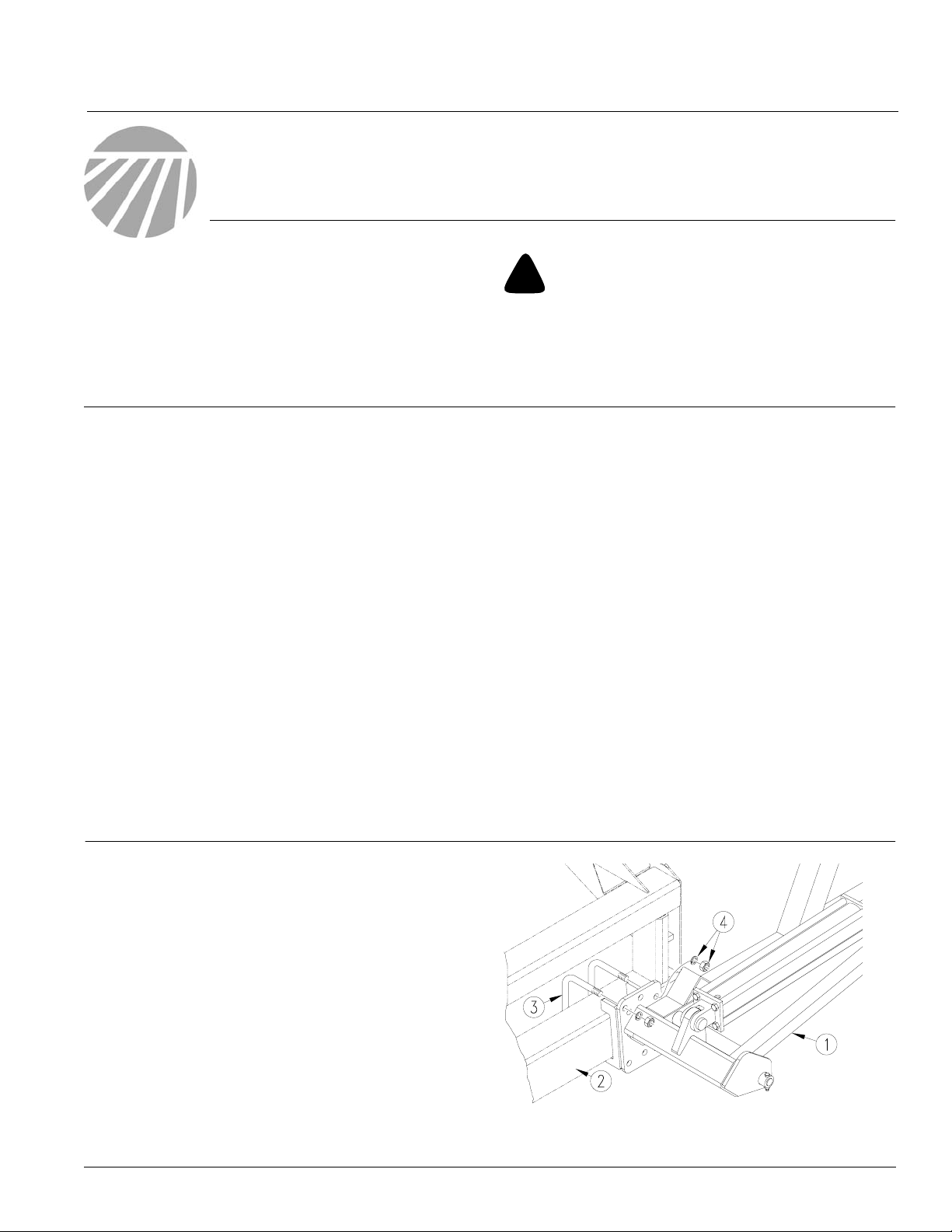
1. Lowerbean machine into fieldposition. Allow
9 feeton each end of a15-foot bean machine
and11feeton each endof a 20-footbeanmachine for marker assembly.
2. Mount first marker section (1) on bean machine 7 x5 inch frametube (2). Mountmarker
as far outon the frame as possible .Secure
marker with 3/4 inchu-bolts (3),lockwashers
and nuts (4).
© Copyright 2000 Printed
3/19/2003
Figure 1
First Marker Section Assembly
113-685M
17727
Rev. A
Page 2
Marker Option
2
Great Plains Mfg., Inc.
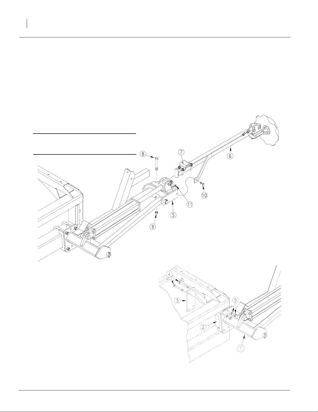
Refer to Figure 2.
3. Remove port plugs on cylinder and carefully
unfold first marker section. Rotate hinge section (5) into a horizontal position.
4. Align holes of break-away section (6) with
holes in hingesection. Bolt sectionstogether
with stop block (7) onbreak-away section facingup.Use 5/8inch pivot bolt (8), lock nut (9),
3/8 x 1 3/4 inch, grade 2 shear bolt (10) and
lock nut (11).
IMPORTANT: Be sure shear bolt is a grade 2
bolt. Failure to use a gr ade 2 bolt can cause
marker damage.
5. Repeat steps for other marker.
6. Adjust markerdisks sothey are square with
ground when markersare lowered in field position. Refer to Marker Adjustments in operator’s manual.
Figure 2
Marker Breakaway Assembly
18534
Marker Assembly, 1515 Alternate Location
If you will beusing the15-footbean machine with
adual-tiretractor,mountmarkersonthe2x 5 inch
vertical frametube toaccommodate thegauge
wheels. To mount markers in alternate location,
you will need Great Plains kit 113-686A.
Refer to Figure 3.
1. Lowerbean machine into fieldposition. Allow
9 feet on eachend of bean machineformarker assembly.
2. Mount first marker section (1) on 2 x 5 inch
vertical frame tube (2).Place mounting plate
(3) behind vertical tube. Use3/4 inch bolts (4)
through markerand mounting plate. Secure
bolts with lock washers and nuts (5).
3. Complete steps 3 through 6 on page 2 to
1515 Alternate Mounting
Figure 3
17814
complete markerassembly.
113-685M 3/19/2003
Page 3
Great Plains Mfg., Inc.
Marker Assembly, 2515 and 2515P
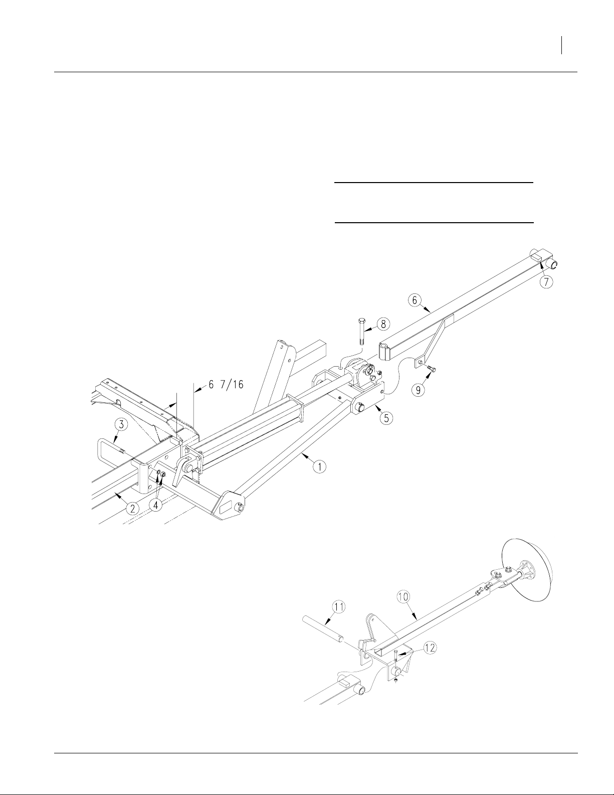
Refer to Figure 4.
1. Lowerbean machine into fieldposition. Allow
15 feet of clearance from each end of bean
machine box formarker assembly.
2. Attach first marker section (1) to 4 x 5 inch
frame tube (2). Mount marker so edge of
mount is 6 7/16 inches in from edge of bean
machine. Secure marker to bean machine
frame with 5/8 inch
u-bolts (3), lock washers and hex nuts (4).
3. Removeport plugs from markercylinder and
carefully unfold first marker section. Rotate
hinge (5) into a horizontal position.
Installation Instructions
4. Assemble second marker section (6) onto
first section so that stop block (7) on second
section faces up.Secure sections with 5/8
inch bolt (8) and lock nut and 3/8 x 2 inch,
grade 2 shear bolt (9) and lock nut.
IMPORTANT:Use a grade 2bolt f orthe shear
bolt or marker damage will occur during field
operation.
3
Marker First and Second Section Assembly
5. Refer to Figure 5. Place third marker section
(10) over end of second section and insert
hinge pin (11)through second- andthird-section pivot. Secure hinge pin with the 1/4 x 2
inch bolt (12) and lock nut.
Figure 4
Figure 5
Marker Third Section Assembly
17728
18535
3/19/2003
113-685M
Page 4

Marker Option
4
Refer to Figure 6.
6. Bolt chain pivot (13) to first marker section
with 3/8 x 3 1/4 inch bolt (14) and lock nut so
chain pivot pivots freely on bolt.
7. Boltchainbar (15) tothirdmarkersectionwith
the 3/8 x 1 1/2 inch bolt (16) and lock nut so
chain bar pivots freely on bolt.
8. Connect markerchain (17)to chainbar and
chainpivotwithutilityclevis(18). With marker
disk adjusted for seeding width and disk
touching the ground, remove chain slack with
utility clevis nearest bean machine.
9. Assemble full-threaded, 3/8 inch stop bolt
(19) and lock nuts on lift-arm extension (20)
so head ofstop bolt extends aslittle as possible.After the markerisbledand folded,adjust
stop bolt to remove slack from chain.Refer to
Marker Chain Adjustments in the operator’s
manual.
Great Plains Mfg., Inc.
Figure 6
Marker Chain Assembly
113-685M 3/19/2003
18536
Page 5

Great Plains Mfg., Inc.
Carrier Assembly, 2015 and 2515
To assemble carrier onto bean machine frame,refer to Figure 7. Referto Table1 for mounting
dimensions.
1. Assemble transport-carrier mount (1) on
bean machine frame. Centermount A inches
fromoutsideend of bean machineframe.Use
1/2 x 6 1/32 x 7 inch
u-bolts (2), flat washers, lock washers and
hex nuts (3). Slide mount forward so its leading edge is about B inches ahead of front
edge of bean machine frame tube.
2. Bolt transport carrier (4) to transport-carrier
mount so topsurfaceof saddle (5)is about C
inches above top of bean machine frame
tube. Secure transportcarrier with 1/2x2x3
inch u-bolts (6), lock washers and hexnuts
(7).
Installation Instructions
Dimension 20-Foot
Bean Machine
Bean Machine
A 38 inches 55 1/2 inches
B 3 1/16 inches 2 5/8 inches
C 29 inches 36 3/8 inches
Table 1
Carrier Mounting Dimensions
5
25-Foot
3. After installing and bleeding hydraulics, trans-
port carrier may require further adjustment.
When folded, the second marker section
should rest in the transport-carrier saddle.
Referto MarkerAdjustments in the operator’s
manual.
3/19/2003
Figure 7
Transport Carrier Assembly
17796
113-685M
Page 6

Marker Option
6
Installing Marker Hydraulics
Without Sequence Valve
Refer to Figure 8.
1. Install elbow fittings (1) in cylinder ports.
2. At rod end ofeach cylinder, install anadaptor
(2) into elbow fitting. Installaneedle valve(3)
in adaptor.
Great Plains Mfg., Inc.
Needle Valve Assembly
3. Connect hydraulic hosesto fittings and route
hydraulic hoses to tractor outlets.Route hydraulichoses throughtransport-carrier mount
at cutout. Use black cableties tosecure hydraulic hoses to bean machine frame.
4. Usingorange cableties, secureaplastic hose
holder to each pair of hydraulic hoses near
tractor outlets. See Figure 9.
5. Proceed with "Bleeding MarkerHydraulics,"
page 8.
Figure 8
Plastic
hose label
Cable tie
Figure 9
Hose Label and Cable Tie
17642
17641
113-685M 3/19/2003
Page 7

Great Plains Mfg., Inc.
With Sequence Valve
Refer to Figure 10.
1. Mount sequence valve (1) on bean machine
using mounting plate (2). Bolt plate to inside
end of left-hand-box panel (3) using one 1/2inch hex bolt (4).
2. Bolt valve to mounting plate with two3/8 x
3/4-inch hex bolts and lock washers (5).
3. Install elbow fittings in cylinderports.Discard
adaptorfitting andtwoneedle valvesprovided
in markerkit.
4. Use hoses provided toconnect valve ports to
cylinders. Refer to Figure 11 for port connections.
5. Connectyourown hydraulichoses to ports on
front of valve.Route hoses to tractor outlets.
Installation Instructions
Figure 10
Sequence Valve Assembly
7
18416
6. Using orange cable tie, secure plastic hose
label to hydraulic hoses near tractor outlets.
See Figure 9 on the previous page.
7. Proceed with "Bleeding MarkerHydraulics,"
page 8.
3/19/2003
Figure 11
Hydraulic Hose Connections
18417
113-685M
Page 8

Marker Option
8
Bleeding Marker Hydraulics
You may be injured if hit by a folding or unfolding
marker. Markers may fall quickly and unexpectedly if
the hydraulics fail. Neverallow anyone near the bean
machine when folding or unfolding the markers.
Escaping fluid under pressurecan have sufficient pressure to penetrate the skin. Check all hydraulic lines
and fittings before applying pressure. Fluid escaping
froma very smallhole can bealmost invisible. Use paper or cardboard, not body parts, and wear heavy
gloves to check for suspected leaks. If injured, seek
medical assistance from a doctor that is familiar with
this type of injury. Foreign fluids in the tissue must be
surgically removed within a few hours or gangrene
will result.
!
CAUTION!
!
WARNING!
Great Plains Mfg., Inc.
1. Check that tractor hydraulic reservoir is full.
2. With both markerslowered into fieldposition,
loosenhydraulic-hosefittings at rod and base
endsof marker cylinders.If applicable,loosen
fittings on back side of sequence valve.
IMPORTANT:Neverbleed anO-ringfitting. Instead, bleed a nearby pipe or JIC fitting.
3. With tractor idling, activate tractor hydraulic
valveuntil oilseeps outarounda loosened fitting. Tighten that fitting.
IMPORTANT: JIC fittings do not require high
torque. JIC and O-ring fittings do not require
sealant. Always use liquid pipe sealant when
adding or replacing pipe-thread fittings. To
avoid crac king hydraulic fittings from over
tightening, do not use plastic sealant tape.
4. Reactivate tractor hydraulic valveuntil oil
seeps out around another loosened fitting.
Tighten that fitting. Repeat process until all
loosened fitting have been bledand tightened.
5. Adjust markerfolding to a safe speed. Refer
to Marker Adjustmentin the operator’s manual.
113-685M 3/19/2003
Page 9

Great Plains Mfg., Inc.
113-666A 15 Ft. Bean Machine Dual Marker
Your kit includes:
Qty. Part No. Part Description
1 113-598V 15’ DUAL FF HOSE BUNDLE
1 113-680K 15FT BM DUAL MARKER BUNDLE
1 113-681K 15FT BM DUAL MARKER HRDWR
1 113-685M MANUAL BM MARKERS-99
2 800-300C CABLE TIE 2 DIA MIN - ORG
2 817-348C PLASTIC HOSE LABEL
113-682A 20 Ft. Bean Machine Dual Marker
Your kit includes:
Installation Instructions
9
Qty. Part No. Part Description
1 113-597V 20’ DUAL FF HOSE BUNDLE
1 113-683K 20FT BM DUAL MARKER BUNDLE
1 113-684K 20FT BM DUAL MARKER HRDWR
1 113-685M MANUAL BM MARKERS-99
2 800-300C CABLE TIE 2 DIA MIN - ORG
2 817-348C PLASTIC HOSE LABEL
2 838-265C DECAL REFLECTOR AMBER 1 1/2
113-663A 25 Ft. Bean Machine Dual Marker
Your kit includes:
Qty. Part No. Part Description
1 113-624V 24’ 3PT DUAL MARKER HOSE B
1 113-678K 25FT BM DUAL MARKER BUNDLE
1 113-679K 25FT BM DUAL MARKER HRDWR
1 113-685M MANUAL BM MARKERS-99
2 800-300C CABLE TIE 2 DIA MIN - ORG
2 817-348C PLASTIC HOSE LABEL
2 838-265C DECAL REFLECTOR AMBER 1 1/2
113-685M3/19/2003
Page 10

Marker Option
10
113-466A 94 3Pt Sequence V alve Field Kit
Your kit includes:
Qty. Part No. Part Description
1 113-488D SEQUENCE VALVE MOUNT BRACK
2 802-014C HHCS 3/8-16X3/4 GR5
2 804-013C WASHER LOCK SPRING 3/8 PLT
1 810-197C VALVE,SEQUENCE SHOEMAKER
4 811-169C EL 9/16MJIC 9/16FJIC
4 811-440C AD 1/2FNPT X 9/16FJICS
1 113-488D SEQUENCE VALVE MOUNT BRACK
2 802-014C HHCS 3/8-16X3/4 GR5
2 804-013C WASHER LOCK SPRING 3/8 PLT
1 810-197C VALVE,SEQUENCE SHOEMAKER
4 811-169C EL 9/16MJIC 9/16FJIC
4 811-440C AD 1/2FNPT X 9/16FJICS
1 113-671H 25 BM LH MARKER MOUNT
Great Plains Mfg., Inc.
113-686A 15 Ft. BM Marker Bolt Plate Kit
Your kit includes:
Qty. Part No. Part Description
2 113-661D BM MARKER MOUNT BOLT PLATE
8 802-095C HHCS 3/4-10X7 GR5
8 803-027C NUT HEX 3/4-10 PLT
8 804-023C WASHER LOCK SPRING 3/4 PLT
3/19/2003
113-685M
 Loading...