

Great Plains 2510HDP Operator Manual

Table of Contents Index
Operator Manual
1510HDP, 2010HDP and 2510HDP
15-, 20-, 25-Foot 3-Point Drills
with 10 Series Heavy Duty Precision Openers
Manufacturing, Inc.
www.greatplainsmfg.com
Read the operator manual entirely. When you see this symbol, the
subsequent instructions and warnings are serious - follow without
exception. Your life and the lives of others depend on it!
27129
Illustrations may show optional equipment not supplied with standard unit or may
depict similar models where a topic is identical.
ORIGINAL INSTRUCTIONS
© Copyright 2013 Printed 2013-10-21 118-245M
Table of Contents Index
EN

Table of Contents Index
Table of Contents Index

Great Plains Manufacturing, Inc. Cover Index iii
Table of Contents
Important Safety Information ...................................... 1
Safety Reflectors and Decals .........................................5
Introduction ................................................................10
Document Family .........................................................10
Description of Unit ........................................................10
Intended Usage ........................................................10
Models Covered .......................................................10
Using This Manual........................................................10
Owner Assistance ........................................................11
Preparation and Setup ...............................................12
Pre-Setup Checklist......................................................12
Hitching ........................................................................12
20- and 25-foot Hitching ...........................................13
Raise Parking Stand (20ft) ...................................13
15-foot Hitching ........................................................14
Electrical Connections..................................................15
Hydraulic Hose Hookup (Options)................................16
Older Style Hoses with Color Ties............................ 17
Leveling the Drill...........................................................18
Leveling: Single-Wheel............................................. 19
Leveling: Offset-Single Wheel ..................................20
Leveling: Dual-Wheel ...............................................21
Options Setup...............................................................22
Acremeter Installation............................................... 22
Seed Monitor Cab Module............................................22
Speed Sensor Installation ........................................22
Hydraulic Console Installation ......................................23
Marker Setup................................................................24
Marker Chain Adjustment.........................................24
Marker Lifting Slack ..............................................24
Folding Slack ........................................................24
Marker Extension Setup ...........................................25
Marker Extension Adjustment...................................25
Operating Instructions...............................................26
Pre-Start Checklist .......................................................26
Prepare for Planting .....................................................26
Transporting ................................................................. 27
Loading Materials .........................................................28
Seed Lubricants .......................................................29
Acremeter Operation ....................................................30
Normal Operating Sequence........................................30
Dormant Display...........................................................30
Field Operation.............................................................31
Marker Operations........................................................32
Independent Markers ............................................... 32
Dual Auto-Sequenced Markers ................................ 32
Both Sides Extended (Sequenced) ...................... 32
Parking......................................................................... 33
Storage ........................................................................ 33
Adjustments ............................................................... 34
Planting Depth ............................................................. 35
Material Rate Adjustments........................................... 35
Main Box Seed Rate ................................................ 36
Range Sprockets.................................................. 37
Transmission Sprockets....................................... 38
Checking Main Box Seed Rate ................................ 38
Checking Singulated Seed Rate ..........................39
Calibrating Volumetric Seed Rate ........................ 40
Small Seeds Attachment Rate ................................. 42
Small Seeds Rate Handle .................................... 42
Small Seeds Rate Calibration ..............................42
Small Seeds Row Shut-Off .................................. 44
Fertilizer Rate...........................................................45
Setting the Fertilizer Adjuster ............................... 45
Fertilizer Density Correction................................. 46
Fertilizer Rate Calibration..................................... 46
Row Unit Adjustments.................................................. 48
Unit-Mounted Coulter Adjustments .......................... 49
Coulter Depth Adjustment .................................... 49
Coulter Row Alignment ........................................ 50
Row Unit Down-Force .............................................. 51
Adjusting Row Unit Down Force .......................... 51
10HDP Series Down-Pressure............................. 52
Available Cam Settings ........................................ 53
Row Unit Shutoff ...................................................... 54
Seed Tube Shutoff ...............................................54
Disengage Meter.................................................. 55
Seed Box Tube Cork............................................ 55
Seed Box Baffles.................................................. 55
Row Unit Lock-Up ................................................56
Shutoff: Remove Seed Meter and Drive .............. 57
Disk Blade Adjustments ........................................... 57
Adjusting Disc Contact ......................................... 58
Meter Adjustments ................................................... 58
Changing Meters.................................................. 59
Changing Precision Seed Wheels........................ 60
Finger Meter Adjustments .................................... 62
Finger Meter Brush Adjustment ........................... 62
Sprocket Indexing (Stagger) ................................ 63
Finger Meter Inserts ............................................. 63
Seed Firmer Adjustments......................................... 64
© Copyright 2008, 2009, 2013 All rights Reserved
Great Plains Manufacturing, Inc. provides this publication “as is” without warranty of any kind, either expressed or implied. While every precaution has been
taken in the preparation of this manual, Great Plains Manufacturing, Inc. assumes no responsibility for errors or omissions. Neither is any liability assumed for
damages resulting from the use of the information contained herein. Great Plains Manufacturing, Inc. reserves the right to revise and improve its products as
it sees fit. This publication describes the state of this product at the time of its publication, and may not reflect the product in the future.
2013-10-21 Cover Index 118-245M
Trademarks of Great Plains Manufacturing, Inc. include: Singulator Plus, Swath Command, Terra-Tine.
Registered Trademarks of Great Plains Manufacturing, Inc. include:
Air-Pro, Clear-Shot, Discovator, Great Plains, Land Pride, MeterCone, Nutri-Pro, Seed-Lok, Solid Stand,
Terra-Guard, Turbo-Chisel, Turbo-Chopper, Turbo Max, Turbo-Till, Ultra-Till, Verti-Till, Whirlfilter, Yield-Pro.
Brand and Product Names that appear and are owned by others are trademarks of their respective owners.
Printed in the United States of America

iv 1510HDP/2010HDP/2510HDP Table of Contents Index Great Plains Manufacturing, Inc.
Keeton Seed Firmer Adjustment .......................... 64
Seed-Lok™ Seed Firmer Lock-Up ....................... 64
Press Wheel Adjustments........................................ 65
Opener Depth (Press Wheel Height) ................... 65
Press Wheel Spacing........................................... 65
Marker Adjustments ..................................................... 66
Marker Disk Angle.................................................... 66
Marker Speed .......................................................... 66
Folding Speed with Needle Valves ...................... 66
Folding Speed with Sequence Valve ................... 67
Hydraulic Drive Operation......................................... 68
Drive Operational Requirements.................................. 68
Hydraulic System: .................................................... 68
Electrical System: .................................................... 68
Tractor Hookup ............................................................ 68
Hydraulics: ............................................................... 68
Electrical: ................................................................. 68
Controller Menu ........................................................... 69
Console Functions ....................................................... 70
Calibration.................................................................... 70
Speed Calibration ........................................................ 75
Operations ................................................................... 78
Before going to the field ........................................... 78
In Field ..................................................................... 78
Hydraulic Drive Calibration....................................... 80
Varying Rates with Pre-set Function............................ 88
GPS-Based Planting .................................................... 89
FarmWorks SiteMate ............................................... 89
GP Precision Population Settings ............................ 89
Troubleshooting with SiteMate................................. 90
Ag Leader PF3000................................................... 91
GP Precision Population Settings ........................ 91
Troubleshooting with PF3000 .................................. 92
Hydraulic Drive Maintenance ....................................... 93
To change the element: ........................................... 93
Hydraulic Drive Troubleshooting.................................. 94
Drive will not rotate: ................................................. 94
Drive rotates but not at desired speed: .................... 95
Calibration Troubleshooting: .................................... 96
Hydraulic Drive Troubleshooting Flow Chart ............... 97
Hydraulic Drive Electronics Troubleshooting ............... 98
Troubleshooting......................................................... 99
Maintenance and Lubrication ................................. 104
Materials Clean-Out ................................................... 104
Main Seed Box Clean-Out ..................................... 104
Small Seeds Box Clean-Out .................................. 104
Fertilizer Clean-Out................................................ 105
Meter Maintenance .................................................... 106
Singulator Plus Meter Maintenance ....................... 106
Singulator Plus Meter Clean-Out ........................107
Finger Meter Maintenance......................................108
Finger Set Installation Instructions......................108
Installation Steps ................................................108
Annual Maintenance ...........................................108
Finger Meter Clean-Out ......................................109
Row Unit Maintenance ...............................................110
Seed Tube Maintenance.........................................110
Sliding Seed Tube Replacement ........................110
Grommet Maintenance ...........................................110
Disk Spreader-Scraper ...........................................111
Seed Flap Replacement .........................................111
Chain Maintenance.....................................................112
Chain Slack.............................................................112
Idler Chain Tension.................................................112
Marker Maintenance...................................................113
Marker Shear Bolt...................................................113
Marker Disk Grease Seal........................................113
Bleeding Marker Hydraulics....................................114
Marker Transport Carrier ........................................115
Lubrication ..................................................................116
Options ......................................................................121
Accessory Hitches ......................................................121
Hitch Setback Kit ........................................................121
Seed Monitor ..............................................................122
Speed Sensors ...........................................................123
Hydraulic Meter Drive .................................................124
Gauge Wheels............................................................125
Weight Bracket Kit ......................................................125
Markers.......................................................................126
Seed Lubricants..........................................................126
Main Seed Box Baffles ...............................................127
Fertilizer......................................................................128
Small Seeds ...............................................................129
Small Seed Tube Plugs ..............................................129
Row Unit Options........................................................130
10HD Series Seed Meters..........................................130
Row Unit Press Wheels..............................................132
Appendix ...................................................................133
Specifications and Capacities.....................................133
Tire Inflation Chart ......................................................135
Torque Values Chart ..................................................136
Row Spacing Data......................................................136
Hydraulic Diagrams ....................................................163
Chain Routing.............................................................166
Warranty .....................................................................169
Index ..........................................................................171
118-245M Table of Contents Index 2013-10-21

Great Plains Manufacturing, Inc. Table of Contents Index 1
Important Safety Information
Look for Safety Symbol
The SAFETY ALERT SYMBOL indicates there is a
potential hazard to personal safety involved and extra
safety precaution must be taken. When you see this
symbol, be alert and carefully read the message that
follows it. In addition to design and configuration of
equipment, hazard control and accident prevention are
dependent upon the awareness, concern, prudence and
proper training of personnel involved in the operation,
transport, maintenance and storage of equipment.
Be Aware of Signal Words
Signal words designate a degree or level of hazard
seriousness.
DANGER indicates an imminently hazardous situation
which, if not avoided, will result in death or serious injury.
This signal word is limited to the most extreme situations,
typically for machine components that, for functional
purposes, cannot be guarded.
WARNING indicates a potentially hazardous situation
which, if not avoided, could result in death or serious
injury, and includes hazards that are exposed when
guards are removed. It may also be used to alert against
unsafe practices.
CAUTION indicates a potentially hazardous situation
which, if not avoided, may result in minor or moderate
injury. It may also be used to alert against unsafe
practices.
Prepare for Emergencies
▲ Be prepared if a fire starts
▲ Keep a first aid kit and fire extinguisher handy.
▲ Keep emergency numbers for doctor, ambulance, hospital
and fire department near phone.
Be Familiar with Safety Decals
▲ Read and understand “Safety Reflectors and Decals”
starting on page 5, thoroughly.
▲ Read all instructions noted on the decals.
▲ Keep decals clean. Replace damaged, faded and illegible
decals.
2013-10-21 Table of Contents Index 118-245M

2 1510HDP/2010HDP/2510HDP Table of Contents Index Great Plains Manufacturing, Inc.
Avoid High Pressure Fluids
Escaping fluid under pressure can penetrate the skin,
causing serious injury.
▲ Avoid the hazard by relieving pressure before disconnecting
hydraulic lines.
▲ Use a piece of paper or cardboard, NOT BODY PARTS, to
check for suspected leaks.
▲ Wear protective gloves and safety glasses or goggles when
working with hydraulic systems.
▲ Hydraulic fluid injected under the skin is an extremely seri-
ous matter. If such an accident occurs, seek urgent medical
attention from a physician familiar with this type of injury.
Wear Protective Equipment
▲ Wear protective clothing and equipment.
▲ Wear clothing and equipment appropriate for the job. Avoid
loose-fitting clothing.
▲ Because prolonged exposure to loud noise can cause hear-
ing impairment or hearing loss, wear suitable hearing protection such as earmuffs or earplugs.
▲ Because operating equipment safely requires your full
attention, avoid wearing entertainment headphones while
operating machinery.
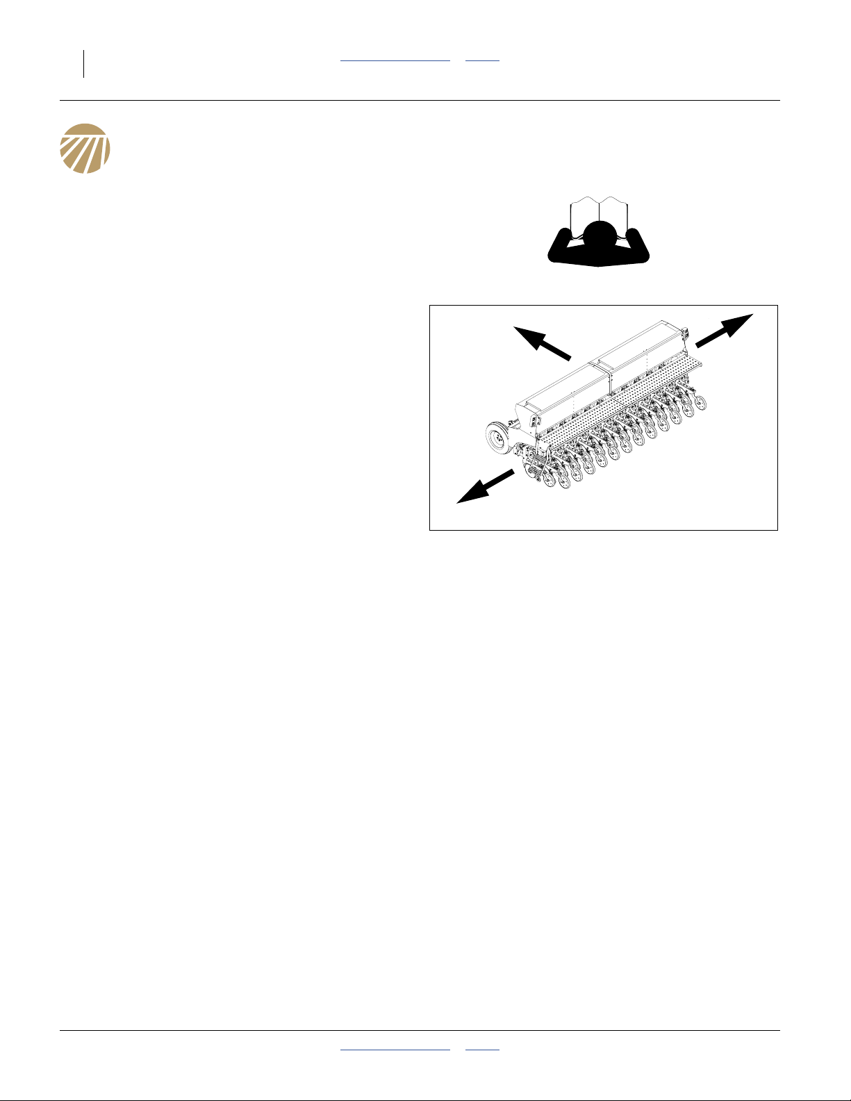
Keep Riders Off Machinery
Riders obstruct the operator’s view. Riders could be
struck by foreign objects or thrown from the machine.
▲ Never allow children to operate equipment.
▲ Keep all bystanders away from machine when fold-
ing/unfolding, raising/lowering markers, raising/lowering
openers, and transporting.
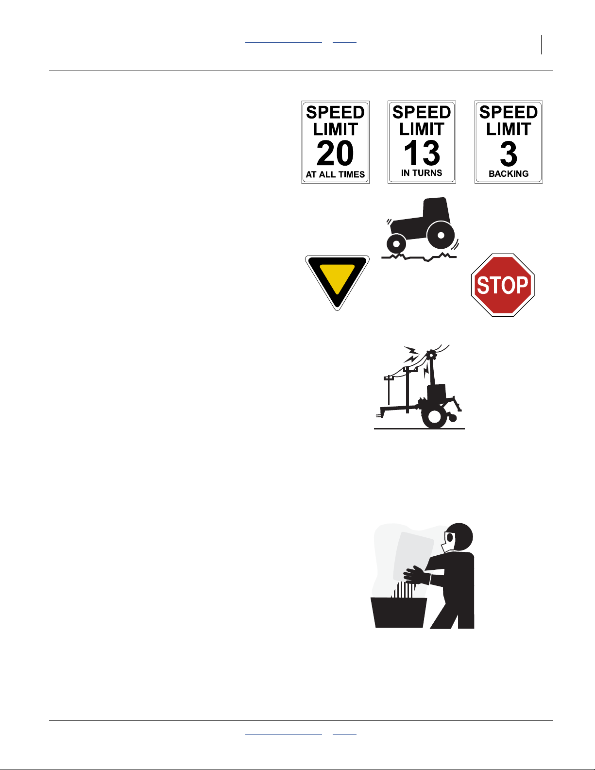
Use Safety Lights and Devices
Slow-moving tractors and towed implements can create
a hazard when driven on public roads. They are difficult
to see, especially at night.
▲ Use flashing warning lights and turn signals whenever driv-
ing on public roads.
▲ Use lights and devices provided with the drill.
118-245M Table of Contents Index 2013-10-21
Great Plains Manufacturing, Inc. Table of Contents Index Important Safety Information 3
Transport Machinery Safely
Maximum transport speed for drill is 20 mph (32 kph).
Some rough terrains require a slower speed. Sudden
braking can cause a towed load to swerve and upset.
▲ Do not exceed 20 mph (32 kph) or the legal speed limit,
whichever is lower. Never travel at a speed which does not
allow adequate control of steering and stopping. Reduce
speed if towed load is not equipped with brakes.
▲ Comply with national, regional and local laws.
▲ Follow your tractor manual recommendations for maximum
hitch loads. Insufficient weight on tractor steering wheels
will result in loss of control.
▲ Carry reflectors or flags to mark drill in case of breakdown
on the road.
▲ Keep clear of overhead power lines and other obstructions
when transporting. Refer to transport dimensions under
“Specifications and Capacities” on page 133.
Check for Overhead Lines
Drill markers contacting overhead electrical lines can
introduce lethal voltage levels on drill and tractor frames.
A person touching almost any metal part can complete
the circuit to ground, resulting in serious injury or death.
At higher voltages, electrocution can occur without direct
contact.
▲ Avoid overhead lines during seed loading/unloading and
marker operations.
Handle Chemicals Properly
Agricultural chemicals can be dangerous. Improper use
can seriously injure persons, animals, plants, soil and
property.
▲ Do not use liquid treatments with drill.
▲ Read and follow chemical manufacturer’s instructions.
▲ Wear protective clothing.
▲ Handle all chemicals with care.
▲ Avoid inhaling smoke from any type of chemical fire.
▲ Never drain, rinse or wash dispensers within 100 feet (30m)
of a freshwater source, nor at a car wash.
▲ Store or dispose of unused chemicals as specified by chemi-
cal manufacturer.
▲ Dispose of empty chemical containers properly. Laws gen-
erally require power rinsing or rinsing three times, followed
by perforation of the container to prevent re-use.
2013-10-21 Table of Contents Index 118-245M

4 1510HDP/2010HDP/2510HDP Table of Contents Index Great Plains Manufacturing, Inc.
Shutdown and Storage
▲ Clean out and safely store or dispose of residual chemicals.
▲ Secure drill using blocks and transport locks.
Lock up openers.
▲ Store in an area where children normally do not play.
Practice Safe Maintenance
▲ Understand procedure before doing work. Use proper tools
and equipment. Refer to this manual.
▲ Work in a clean, dry area.
▲ Put tractor in park, turn off engine, and remove key before
performing maintenance.
▲ Make sure all moving parts have stopped and all system
pressure is relieved.
▲ Disconnect battery ground cable (-) before servicing or
adjusting electrical systems or before welding on drill.
▲ Inspect all parts. Make sure parts are in good condition and
installed properly.
▲ Remove buildup of grease, oil or debris.
▲ Remove all tools and unused parts from drill before opera-
tion.
Tire Safety
Tire changing can be dangerous and should be
performed by trained personnel using correct tools and
equipment.
▲ When inflating tires, use a clip-on chuck and extension hose
long enough for you to stand to one side–not in front of or
over tire assembly. Use a safety cage if available.
▲ When removing and installing wheels, use wheel-handling
equipment adequate for weight involved.
118-245M Table of Contents Index 2013-10-21

Great Plains Manufacturing, Inc. Table of Contents Index Important Safety Information 5
Safety At All Times
Thoroughly read and understand the instructions in this
manual before operation. Read all instructions noted on
the safety decals.
▲ Be familiar with all drill functions.
▲ Operate machinery from the driver’s seat only.
▲ Do not leave drill unattended with tractor engine running.
▲ Do not dismount a moving tractor. Dismounting a moving
tractor could cause serious injury or death.
▲ Do not stand between the tractor and drill during hitching.
▲ Keep hands, feet and clothing away from power-driven
parts.
▲ Wear snug-fitting clothing to avoid entanglement with mov-
ing parts.
▲ Watch out for wires, trees, etc., when folding and raising
drill. Make sure all persons are clear of working area.
Safety Reflectors and Decals
Your drill comes equipped with all lights, safety reflectors
and decals in place. They were designed to help you
safely operate your drill.
▲ Read and follow decal directions.
▲ Keep lights in operating condition.
▲ Keep all safety decals clean and legible.
▲ Replace all damaged or missing decals. Order new decals
from your Great Plains dealer. Refer to this section for
proper decal placement.
▲ When ordering new parts or components, also request cor-
responding safety decals.
To install new decals:
1. Clean the area on which the decal is to be placed.
2. Peel backing from decal. Press firmly on surface,
being careful not to cause air bubbles under decal.
2013-10-21 Table of Contents Index 118-245M
6 1510HDP/2010HDP/2510HDP Table of Contents Index Great Plains Manufacturing, Inc.
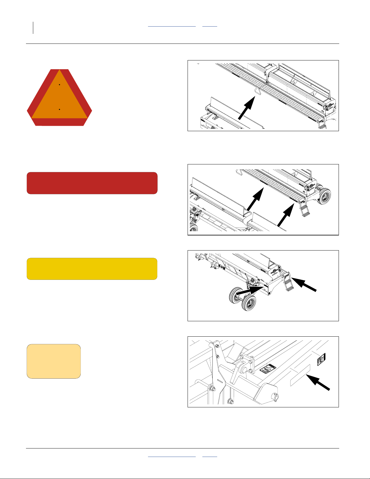
Slow Moving Vehicle Reflector
818-055C
reflector is mounted at center rear edge of walkboard(s);
1 total
Red Reflectors
838-266C
Rear walkboard face, outside corner (all models),
rear walkboard face, center (2010HDP and 2510HDP);
2 or 4 total
27130
27130
Amber Reflectors (large)
838-265C
On outside end faces of walkboards at ladder top,
front top face of mainframe, each outside corner;
4 total
Amber Reflectors, small (Option)
818-229C
On front face of first section of marker;
1 total per marker
27130
18270
118-245M Table of Contents Index 2013-10-21
Great Plains Manufacturing, Inc. Table of Contents Index Important Safety Information 7
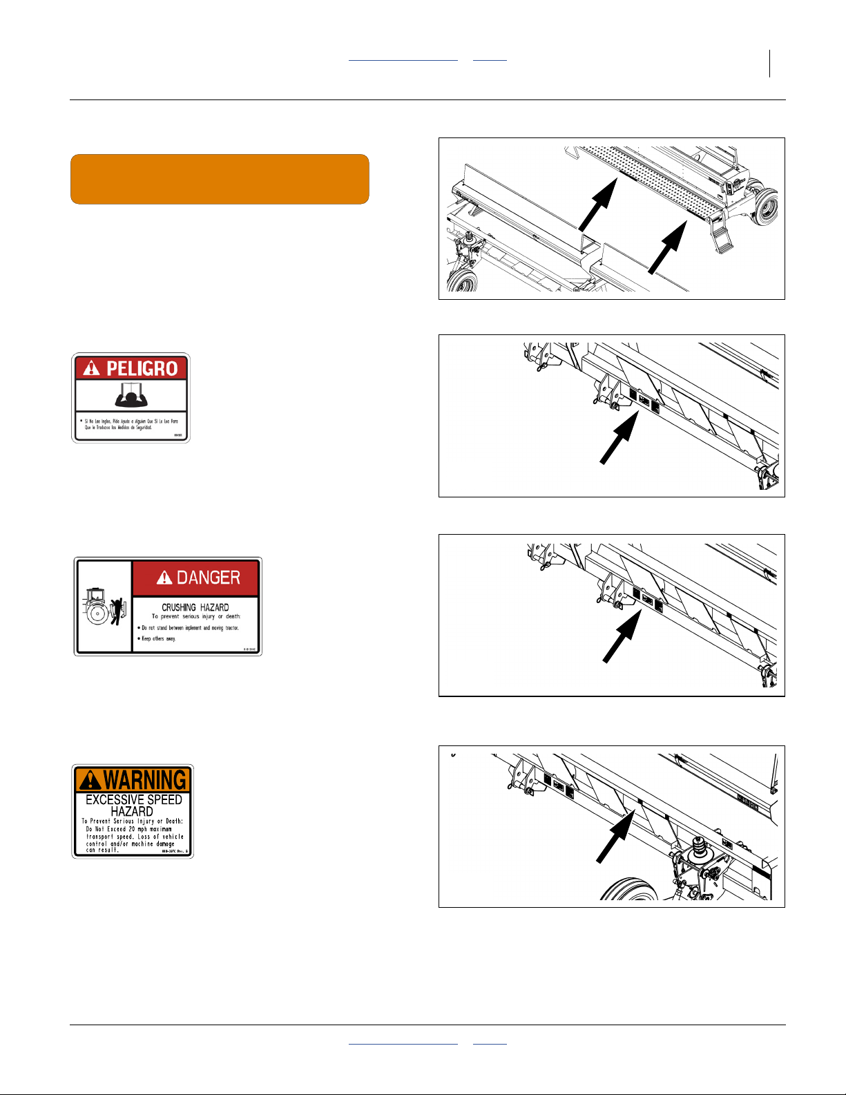
Daytime Reflectors
838-267C
Rear walkboard face, inboard of red reflectors;
2 (on 1510HDP) or
4 (on 2010HDP and 2510HDP) total
27130
Danger: Cannot Read English
818-557C
On front face of mainframe near hitch;
1 total
Danger: Crushing Hazard
818-590C
On front face of mainframe, right of 3-point hitch;
1 total
Warning: Excessive Speed Hazard
27130
27130
818-337C
On front face, top front of mainframe, above each gauge
wheel assembly;
2 total
2013-10-21 Table of Contents Index 118-245M
27130
8 1510HDP/2010HDP/2510HDP Table of Contents Index Great Plains Manufacturing, Inc.
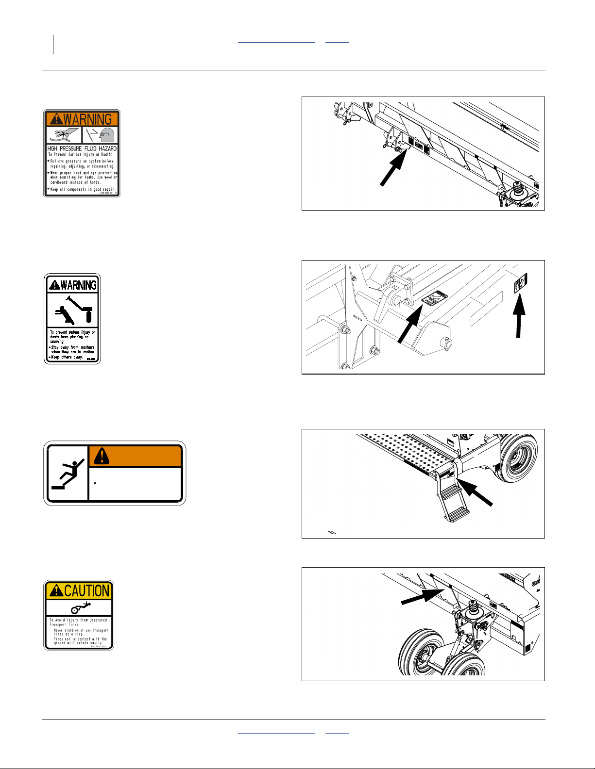
Warning: High Pressure Fluid
27130
818-339C
On front face of mainframe, right of 3-point hitch;
1 total
Warning: Marker Pinch Crush (Option)
818-682C
On front and top faces, inner marker section,
2 per marker; 4 total
Warning: Falling Hazard
WARNING
To avoid serious injury or death:
Watch your step when climbing ladder or
walking on walkboard.
838-102C
On outside face of mainframe, forward of ladder;
2 total
Caution: Tires Not A Step
838-102C
18270
27130
818-398C
On front face, top front of mainframe, above each gauge
wheel assembly;
2 total
118-245M Table of Contents Index 2013-10-21
27130
Great Plains Manufacturing, Inc. Table of Contents Index Important Safety Information 9
Caution: Read Manual
818-587C
On front face of mainframe, right of 3-point hitch;
1 total
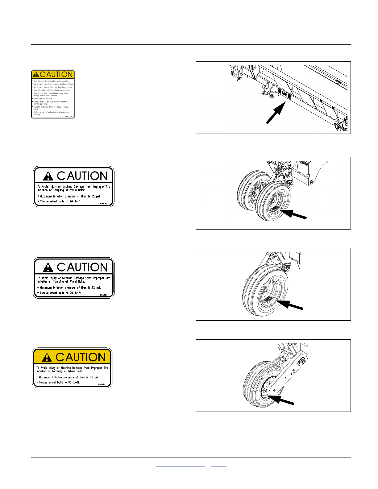
Caution: 32 PSI Tire Pressure
818-751C
On rim of each 9.5L-15-6ply wheel;
2 total
Caution: 52 PSI Tire Pressure
27130
24379
818-752C
On rim of each 11L-15SL-12ply wheel;
2 total
27225
Caution: 36 PSI Tire Pressure
818-855C
On rim of each 11L-15SL-8ply wheel;
4 total
2013-10-21 Table of Contents Index 118-245M
26216
10 1510HDP/2010HDP/2510HDP Table of Contents Index Great Plains Manufacturing, Inc.
Introduction
Great Plains welcomes you to its growing family of new
product owners. Your 3-Point Drill has been designed
with care and built by skilled workers using quality
materials. Proper setup, maintenance, and safe
operating practices will help you get years of satisfactory
use from the machine.
Document Family
Great Plains parts:
118-245M Operator Manual (this document)
118-245P 2510HDP Parts Manual
118-928P 2010HDP Parts Manual
119-949P 1510HDP Parts Manual
118-245B Seed Rate Manual
DICKEY-john parts:
11001-1359-200605Seed Monitor Manual
R
Description of Unit
The products covered by this manual are 15-, 20- and
25-foot 3-point mounted seed drills. They are equipped
with HD10 Series heavy duty row units and precision
seed meters.
Intended Usage
Use this implement to seed production-agriculture crops
in conventional or minimum tillage applications.
Models Covered
1510HDP-12TR 15-Foot, 12-Twin Row (6 pair), 30in
1510HDP-1315 15-Foot, 13-Row, 15in
1510HDP-1910 15-Foot, 19-Row, 10in
1510HDP-19TRS 15-Foot, 19-Row Twin Split
(6 pairs on 30in, plus 7 singles)
1510HDP-2475 15-Foot, 24-Row, 7.5in
2010HDP-16TR 20-Foot, 16-Twin Row (8 pair), 30in
2010HDP-1715 20-Foot, 17-Row, 15in
2010HDP-2510 20-Foot, 25-Row, 10in
2010HDP-25TRS 20-Foot, 25-Twin Row Split
(8 pairs on 30in, plus 9 singles)
2010HDP-3275 20-Foot, 32-Row, 7.5in
2510HDP-2015 25-Foot, 20-Row, 15in
2510HDP-20TR30 25-Foot, 20-Twin Row (10 pair), 30in
2510HDP-2910 25-Foot, 29-Row, 10in
2510HDP-29TRS 25-Foot, 29-Twin Row Split
(10 pairs on 30in, plus 9 singles)
2510HDP-4075 25-Foot, 40-Row, 7.5in
L
Figure 1
Left/Right Notation
18327
Using This Manual
This manual familiarizes you with safety, assembly, operation, adjustments, troubleshooting, and maintenance.
Read this manual and follow the recommendations to
help ensure safe and efficient operation.
The information in this manual is current at printing.
Some parts may change to assure top performance.
Definitions
The following are used throughout this manual.
Right-hand and left-hand as used in this manual are
determined by facing the direction the machine will travel
while in use unless otherwise stated.
Paragraphs in this format present a crucial point of
information related to the current topic.
Read and follow the directions to:
- remain safe,
- avoid serious damage to equipment and
- ensure desired field results.
Note: Paragraphs in this format provide useful informa-
tion related to the current topic.
118-245M Table of Contents Index 2013-10-21
Great Plains Manufacturing, Inc. Table of Contents Index Introduction 11
Owner Assistance
If you need customer service or repair parts, contact a
Great Plains dealer. They have trained personnel, repair
parts and equipment specially designed for Great Plains
products.
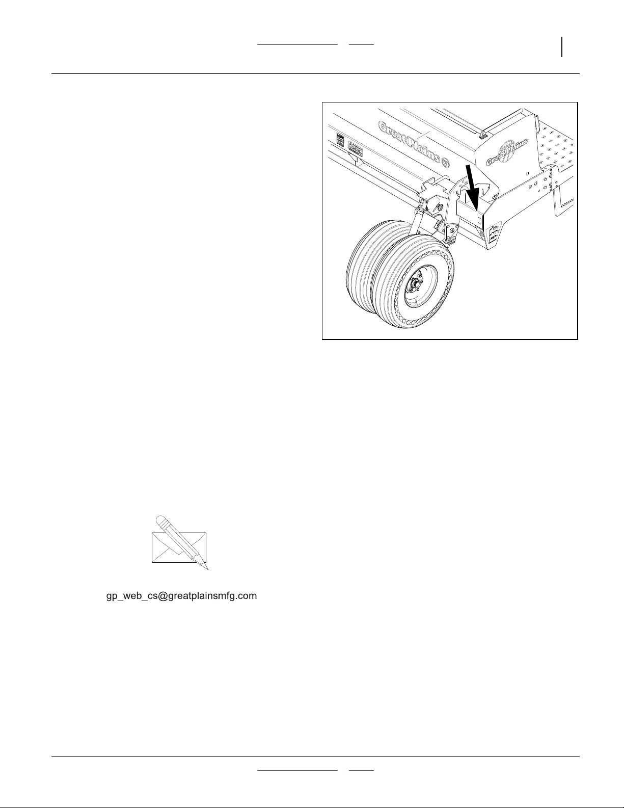
Refer to Figure 2
Your machine’s parts were specially designed and
should only be replaced with Great Plains parts. Always
use the serial and model number when ordering parts
from your Great Plains dealer. The serial-number plate is
located on the left side of the drill frame below the front
of the main seed box.
Record your drill model and serial number here for quick
reference:
Model Number:__________________________
Serial Number: __________________________
Your Great Plains dealer wants you to be satisfied with
your new machine. If you do not understand any part of
this manual or are not satisfied with the service received,
please take the following actions.
1. Discuss the matter with your dealership service
manager. Make sure they are aware of any problems
so they can assist you.
2. If you are still unsatisfied, seek out the owner or
general manager of the dealership.
For further assistance write to:
Figure 2
Serial Number Location
16490
Product Support
Great Plains Mfg. Inc., Service Department
PO Box 5060
Salina, KS 67402-5060
785-823-3276
2013-10-21 Table of Contents Index 118-245M

12 1510HDP/2010HDP/2510HDP Table of Contents Index Great Plains Manufacturing, Inc.
Preparation and Setup
This section helps you prepare your tractor and drill for
use. Before using the drill in the field, you must hitch the
drill to a suitable tractor and also setup the drill.
Pre-Setup Checklist
1. Read and understand “Important Safety
Information” starting on page 1.
2. Check that all working parts are moving freely, bolts
are tight, and cotter pins are spread.
3. Check that all grease fittings are in place and
lubricated. “Lubrication” starting on page 116.
4. Check that all safety decals and reflectors are
correctly located and legible. Replace if damaged.
“Safety Reflectors and Decals” starting on page 5.
5. Inflate tires to pressure recommended and tighten
wheel bolts as specified. “Appendix” on page 133.
Hitching
You may be severely injured or killed by being crushed
between the tractor and drill. Do not stand or place any part of
your body between machines being hitched. Stop tractor and
set parking brake before inserting hitch pins.
118-245M Table of Contents Index 2013-10-21
Great Plains Manufacturing, Inc. Table of Contents Index Preparation and Setup 13
20- and 25-foot Hitching
15-foot hitching is on page 14.
These instructions are for a direct 3-point hitch. If using
an optional CPH, PFH or SSH hitch (model 2010HDP
only), consult the hitch manual.
3
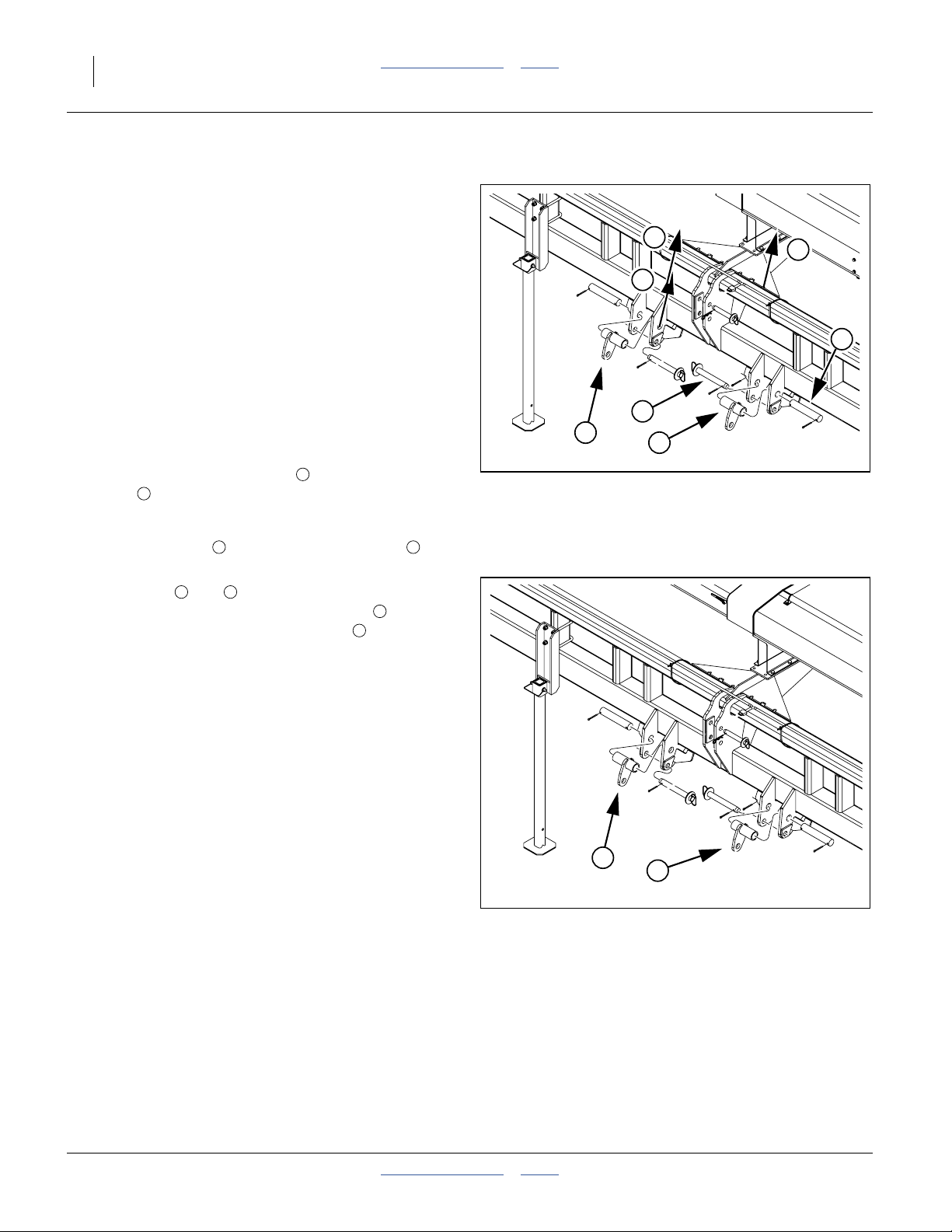
Hitch Setup (20/25ft)
Refer to Figure 3
1. For tractors with category III and III-N hitches,
position the center/upper pin in the bottom center
2
holes .
For tractors with category IV-N hitches, position the
center/upper pin in the upper center holes
2. Make sure the lower pins are in the bottom holes
5
of the lower hitch weldments, and that the spacers
6
are present.
Routine Hitching (20/25ft)
3. Make sure all cables and hoses are clear of the hitch
area.
4. For a “quick hitch”, align lower arms with lower hitch
points, set spacers and engage lower arms.
For pinned hitch, remove pins and spacers, align
hitch arms and re-pin.
5. Slowly raise drill, watching for cab interference.
6. Adjust top link so that when in field position, top side
of drill mainframe is parallel to the ground.
Note: Do not use 3-point link to adjust opener depth. See
“Planting Depth” on page 35 for a summary of
depth control settings.
7. Set tractor three-point draft control to Float.
8. Skip to “Electrical Connections” on page 15.
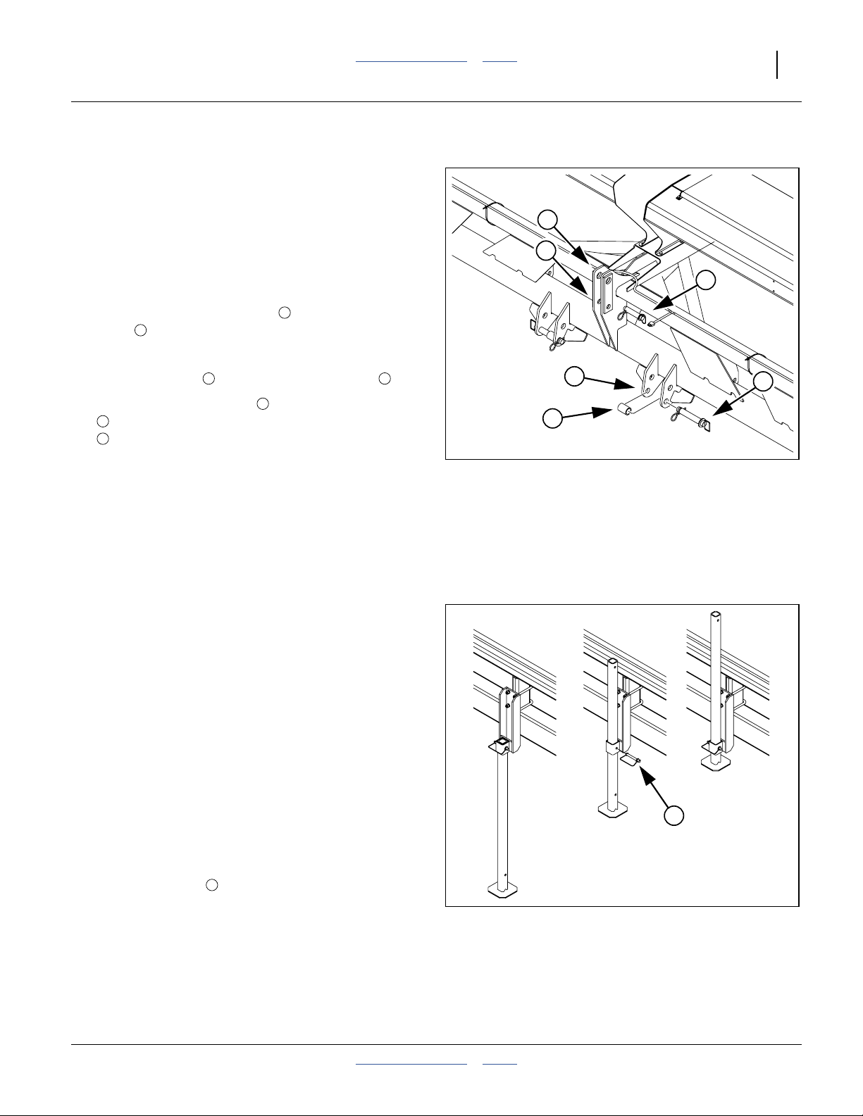
Raise Parking Stand (20ft)
Only the 15- and 20-foot drills have these stands (one on
each side). The stand is primarily needed when an
accessory hitch is used.
9. Make sure the drill raising at step 5 above has
removed all weight carried by the stands.
1 3
1
4
2
5
6
Figure 3
25-foot 3-Point Hitch
1
4
27408
7
10. Remove the pins .
11. Slide the stand tube up in the sleeve (you may also
invert the tube, with the foot plate on top).
12. Re-insert the pin.
2013-10-21 Table of Contents Index 118-245M
7
Figure 4
Raise Parking Stand
27410
14 1510HDP/2010HDP/2510HDP Table of Contents Index Great Plains Manufacturing, Inc.
15-foot Hitching
20- and 25-foot hitching is on page 13.
These instructions are for a direct 3-point hitch. If using
an optional CPH, PFH or SSH hitch, consult the hitch
manual.
Hitch Setup (15ft)
Some tractor 3-points may require additional bushings
(not supplied by Great Plains) to adapt the pin diameters:
Upper Link: Qty 1, 1in ID x 1
Lower Link: Qty 2, 1
1
⁄
8
1
in ID x 1
⁄
in OD
4
7
⁄
16
in OD
Refer to Figure 5 and Figure 6
As supplied from the factory, 1510HDP hitches are set
for category II.
1. For tractors with category III and III-N hitches,
position the center/upper pin in the bottom center
2
holes .
1
6
15-foot Category II Hitch
3
2
4
6
Figure 5
1
5
27409
For tractors with category IV-N hitches, position the
center/upper pin in the upper center holes
1 2
2. For tractors with category III hitches, remove all
lower pins ( and ) and re-position the pin
supports from their category II positions on the
top pins to their category III positions as shown in
4 5
6
7
Figure 6.
Routine Hitching (15ft)
Refer to Figure 5 and Figure 6
3. Raise or lower tractor three-point arms as needed
and pin lower arms to drill.
4. Pin upper arm to drill.
For category II, III and III-N tractors, install hitch pin
in the lower hole.
For category IV-N tractors, install hitch pin in the
upper hole.
5. Slowly raise drill. Watch for cab interference.
6. If drill has parking stands, pin them up. See page 13
for details.
7. Adjust top three-point link so that top edge of drill
box is parallel with ground when drilling.
Note: Do not use link to adjust opener depth. For opener
adjustments, refer to “Leveling the Drill” on page
18 and “Adjustments” starting on page 34.
8. Set your tractor three-point-Control control to Float
position.
7
7
Figure 6
15-foot Category III Hitch
27409
118-245M Table of Contents Index 2013-10-21
Great Plains Manufacturing, Inc. Table of Contents Index Preparation and Setup 15
Electrical Connections
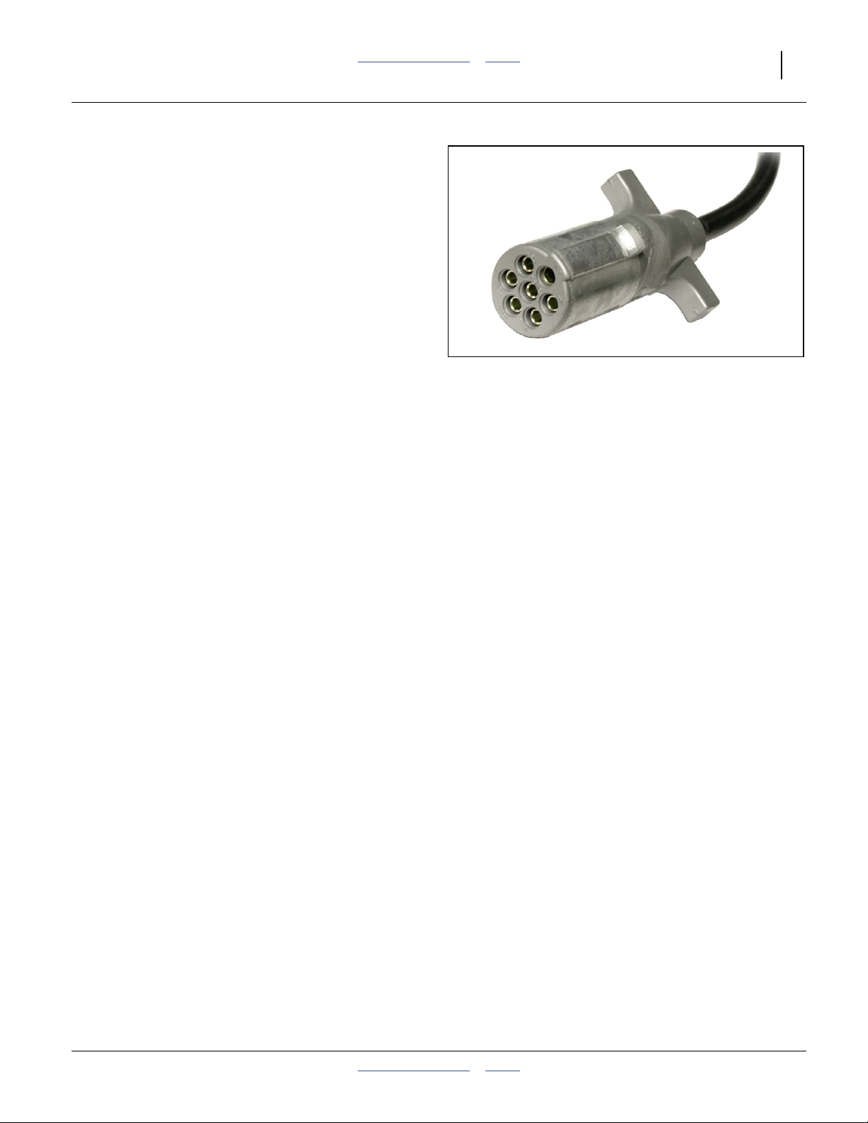
Refer to Figure 7
9. Plug drill electrical lead into tractor seven-pin
connector. If your tractor is not equipped with a
seven-pin connector, contact your dealer for
installation.
10. If the drill is equipped with the optional seed monitor,
mate the connector for the cab console.
See “Seed Monitor Cab Module” on page 22 for
installation.
See “Seed Monitor” on page 122 for ordering
information.
11. If the drill is equipped with the optional hydraulic
meter drive, mate the connector for the cab console.
See “Hydraulic Console Installation” on page 23 for
installation.
See “Hydraulic Meter Drive” on page 124 for ordering
information.
12. If the drill is equipped with one or more speed
sensors (radar and.or magnetic) mounted on the drill
mate the connectors for the cab displays.
See “Speed Sensor Installation” on page 22 for
installation.
See “Speed Sensors” on page 122 for ordering
information.
Figure 7
Lighting Connector
36051
2013-10-21 Table of Contents Index 118-245M
16 1510HDP/2010HDP/2510HDP Table of Contents Index Great Plains Manufacturing, Inc.
Hydraulic Hose Hookup (Options)
Only trained personnel should work on system hydraulics!
Escaping fluid under pressure can have sufficient pressure to
penetrate the skin, causing serious injury. Avoid the hazard by
relieving pressure before disconnecting hydraulic lines. Use a
piece of paper or cardboard, NOT BODY PARTS, to check for
leaks. Wear protective gloves and safety glasses or goggles
when working with hydraulic systems. Hydraulic fluid injected
under the skin is an extremely serious matter. If such an
accident occurs, seek urgent medical attention from a
physician familiar with this type of injury.
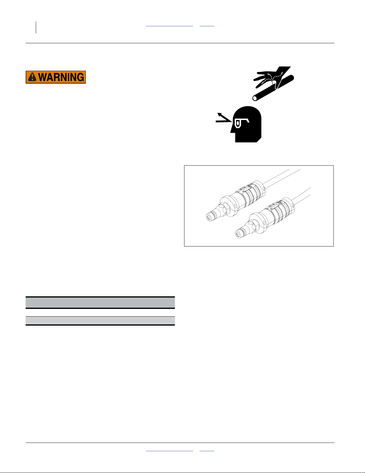
Refer to Figure 8
Great Plains hydraulic hoses have color coded handle
grips to help you hookup hoses to your tractor outlets.
Hoses that go to the same remote valve are marked with
the same color.
To distinguish hoses on the same hydraulic circuit, refer
to the symbol molded into the handle grip. Hoses with an
extended-cylinder symbol feed cylinder base ends.
Hoses with a retracted-cylinder symbol feed cylinder rod
ends.
For hydraulic fan and drive motors, connect the hose
under the retracted cylinder symbol to the pressure side
of the motor. Connect the hose under the extended
cylinder symbol to the return side of the motor.
These instructions presume a direct tractor-drill 3-point
hitching. If an accessory hitch is used, hose routing and
color coding may vary, and there will be one or two
additional circuits (for the hitch lift and tongue).
Figure 8
Color Coded Hose Grips
31733
Color Hydraulic Function
Green Marker Cylinders
Yellow Hydraulic Meter Drive
13. Connect meter drive hoses to tractor remote valve.
14. The optional hydraulic meter drive requires
continuous flow. If the tractor has only one circuit so
rated, or a priority circuit, use that circuit for the drive.
See “Drive Operational Requirements” on page 68
for circuit requirements.
15. Connect marker hoses to tractor remote valve.
16. If this is the first time the drill has been hitched, bleed
the marker hydraulics per the instructions on
page 114.
118-245M Table of Contents Index 2013-10-21
Great Plains Manufacturing, Inc. Table of Contents Index Preparation and Setup 17
Older Style Hoses with Color Ties
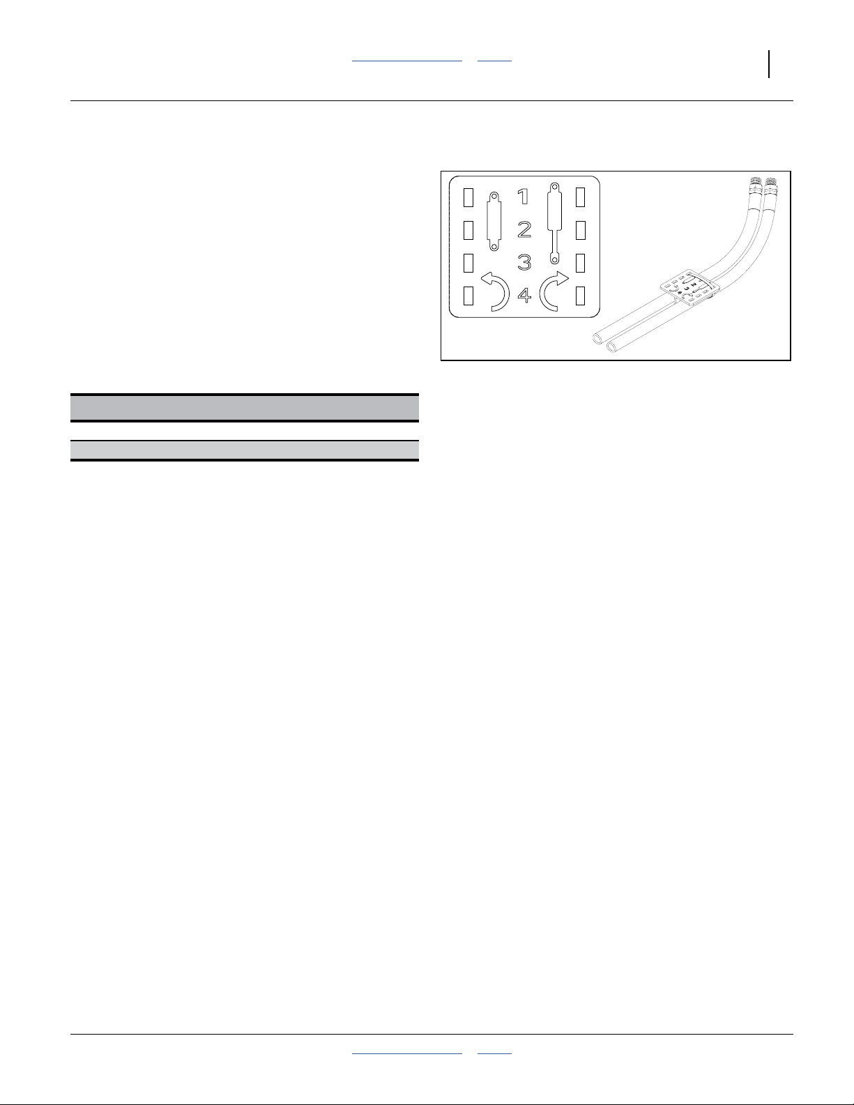
Refer to Figure 8
To distinguish hoses on the same hydraulic circuit, refer
to plastic hose label. The hose under an
extended-cylinder symbol feeds a cylinder base end. The
hose under a retracted-cylinder symbol feeds a cylinder
rod end.
Great Plains hydraulic hoses are color coded to help you
hookup hoses to your tractor outlets.Hoses that go to the
same remote valve are marked with the same color tie.
These instructions presume a direct tractor-drill 3-point
hitching. If an accessory hitch is used, hose routing an
color coding may vary, and there will be one or two
additional circuits (for the hitch lift and tongue).
Color Hydraulic Function
Orange Marker Cylinders
Yellow Hydraulic Meter Drive
Figure 9
Older Style Hoses with Label
817-348c
17641
2013-10-21 Table of Contents Index 118-245M

18 1510HDP/2010HDP/2510HDP Table of Contents Index Great Plains Manufacturing, Inc.
Leveling the Drill
For proper operation, and maximum compensation for
varying ground conditions, the opener parallel arms need
to be parallel to slightly up-hill in normal lowered field
operation. This is controlled by two factors:
• the opener tool bar height, which is controlled by
adjustments to the gauge wheels, and;
• front-to-back level, which is controlled by the 3-point
hitch.
The procedure for setting initial drill height and checking
front-to-back level is:
1. Set gauge wheel adjustments to bedded or
non-bedded, via turnbuckle or link and block.
2. Lower drill onto gauge wheels with 3-point.
Set circuit to Float.
3. Adjust 3-point to recommended initial opener tool
bar height.
4. Verify front-to-back level, and adjust with 3-point.
Re-check height.
The adjustment details are different for single gauge
wheel vs. dual gauge wheel or offset single.
See the appropriate page for your drill:
Single-Wheel page 19
Dual- or Offset-Single Wheel page 20
Make the same adjustment on both gauge wheel
assemblies.
Check that drill is still level side-to-side after setup.
118-245M Table of Contents Index 2013-10-21
Great Plains Manufacturing, Inc. Table of Contents Index Preparation and Setup 19
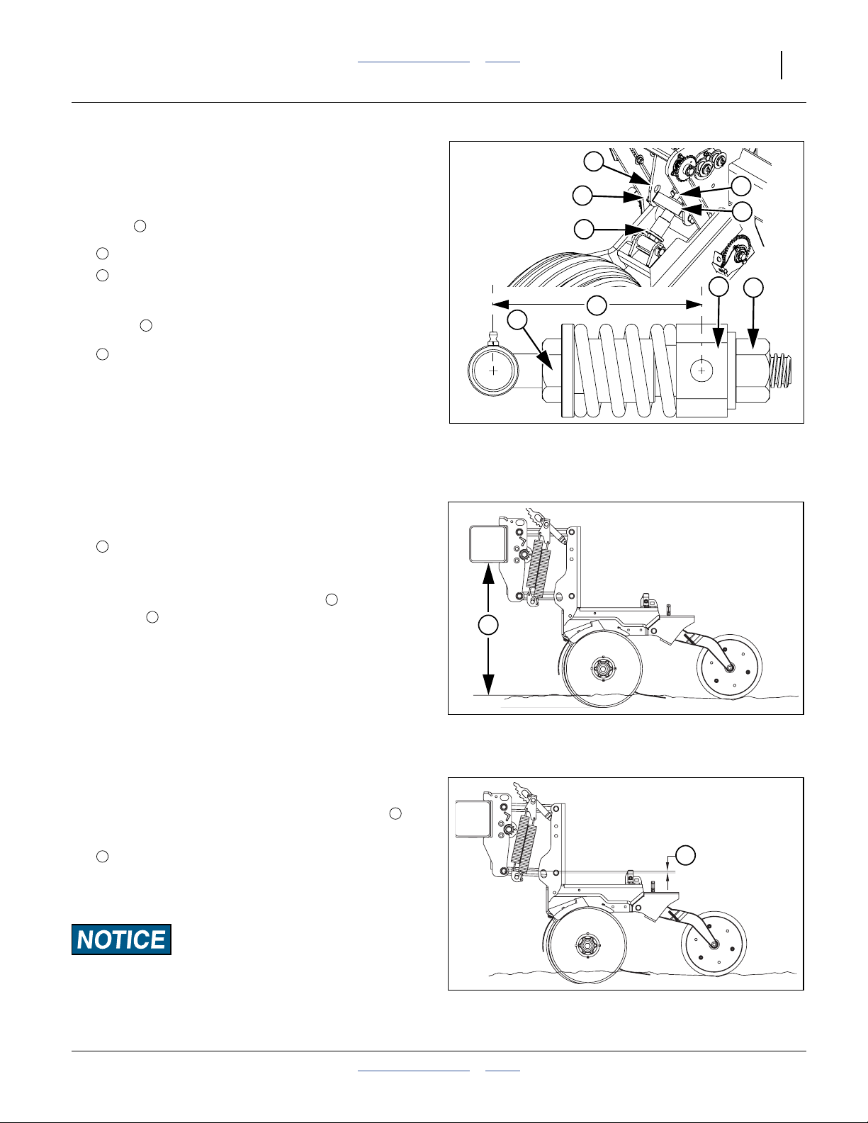
Leveling: Single-Wheel
3
Refer to Figure 10
1. If operations are being changed between
non-bedded and bedded planting, set the spring
1
block position before checking opener height.
2
Lower hole Bedded planting
3
Upper hole Non-Bedded planting
2. Check the link length. The factory setting for link
length , measured at centerlines, is:
4
3. Lower the drill in representative field conditions and
set the 3-point hitch circuit to Float.
4
Link Length
1
6
⁄
in (16.5cm)
2
2
6
4
6
5
1
1
5
Refer to Figure 11
Note: This presumes a planting depth of 1.75in (44mm).
If your depth is different, re-adjust the tool bar
height when adjusting the press-wheel (page 65).
4. Initially adjust drill distance between bottom of
opener tool bar and planting ground:
7
Tool bar height 26in (66cm)
Refer to Figure 10
5. To adjust link length, loosen jam nut . Turn spring
linkage to shorten or lengthen as necessary.
When adjusting the linkage length, remember:
+ Lengthening linkage raises drill.
- Shortening linkage lowers drill.
Re-tighten jam nut when height is final.
Refer to Figure 12
6. Level drill with top of three-point link. Adjust so that
row units are inclined slightly uphill, measured at
the ends of the parallel arms:
6
5
8
Figure 10
Single Wheel Link
26216
26217
7
Figure 11
Single-Wheel Height
24046
8
Arm inclination 1in (2.5cm) maximum
The 1in/2.5cm dimension shown is a general dimension
that varies with planting conditions.
Ensure the opener mount is running higher than the opener
body. This ensures ample reserve for opener upfloat if the
opener strikes a rock or other object.
Single-Wheel Opener Level
2013-10-21 Table of Contents Index 118-245M
Figure 12
8
24047
20 1510HDP/2010HDP/2510HDP Table of Contents Index Great Plains Manufacturing, Inc.
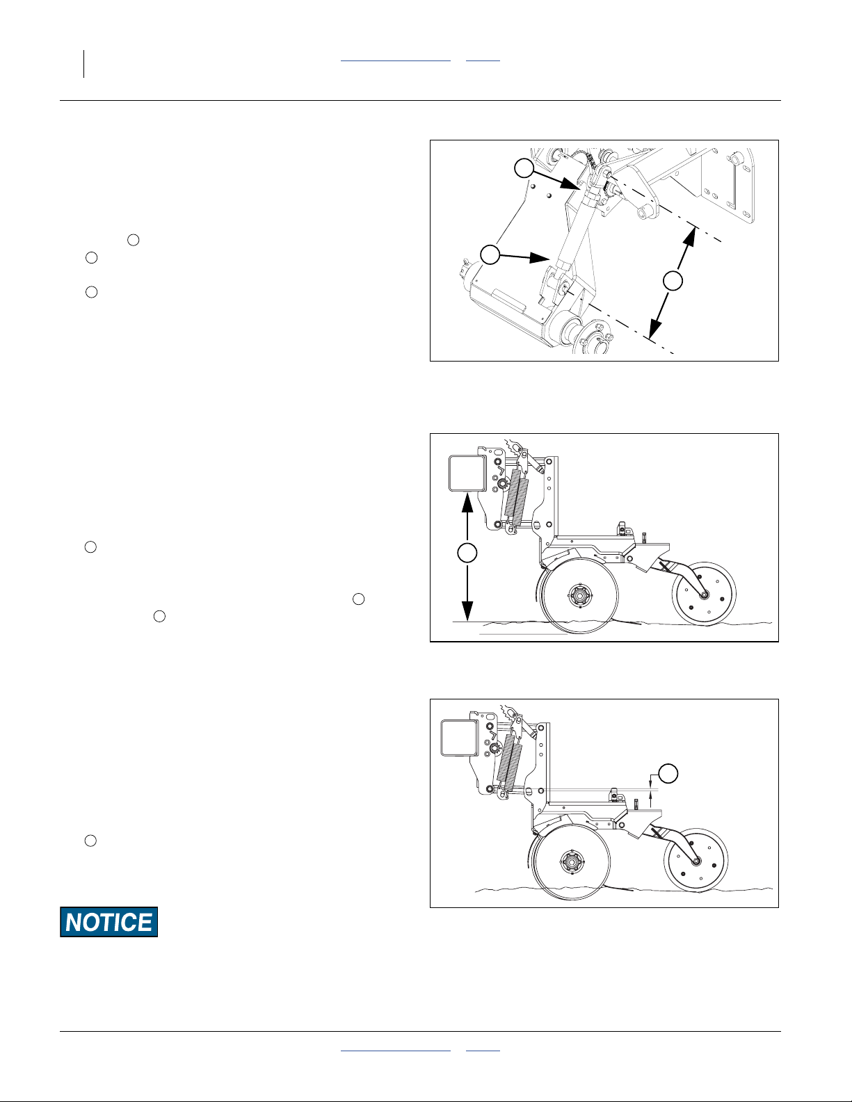
Leveling: Offset-Single Wheel
The offset-single gauge wheel adjusts for bedding by
changing the turnbuckle length.
Refer to Figure 13
1. Check the link length. The factory setting for link
17
1
1
⁄
in (44.5cm)
2
length , measured at centerlines, is:
1
This corresponds to an opener tool bar height of:
4
26in (66cm)
This is for non-bedded planting.
To adjust the drill for bedded planting:
2. Hitch it to a suitable tractor. Move it to representative
bedded ground, with the wheels between beds.
3. Lower the drill to planting position and set the 3-point
hitch circuit to Float.
Refer to Figure 14
Note: This presumes a planting depth of 1.75in (44mm).
If your depth is different, re-adjust the tool bar
height when adjusting the press-wheels (page 65).
4. Adjust drill distance between bottom of opener tool
bar and planting ground (bed tops):
2
3
Figure 13
Offset-Single Wheel Turnbuckle
1
27221
4
Tool bar height 26in (66cm)
Refer to Figure 13
5. To adjust turnbuckle length, loosen jam nut . Turn
turnbuckle to shorten or lengthen as necessary.
3
2
When adjusting the turnbuckle length, remember:
+ Lengthening turnbuckle raises drill.
- Shortening turnbuckle lowers drill.
Re-tighten jam nut when height is final.
Note: Do not expose more than 3in (7.6cm) of thread at
either end of turnbuckle.
6. Level drill with top three-point link.
Refer to Figure 15
7. Level drill with top of three-point link. Adjust so that
row units are inclined slightly uphill, measured at the
ends of the parallel arms:
7
Arm inclination 1in (2.5cm) maximum
The 1in/2.5cm dimension shown is a general dimension
that varies with planting conditions.
Ensure the opener mount is running higher than the opener
body. This ensures ample reserve for opener upfloat if the
opener strikes a rock or other object.
4
Figure 14
Offset-Single Wheel Height
Figure 15
Offset-Single Wheel Opener Level
24050
7
24047
118-245M Table of Contents Index 2013-10-21

Great Plains Manufacturing, Inc. Table of Contents Index Preparation and Setup 21
Leveling: Dual-Wheel
2
Refer to Figure 16
1. If operations are being changed between
non-bedded and bedded planting, set the spring
turnbuckle clevis position before checking length and
opener height.
1
Lower hole Bedded planting
2
Upper hole Non-Bedded planting
5
1
3
2. Check the link length. The factory setting for link
length , measured at centerlines, is:
3
Non-Bedded Bedded
1
3
17
⁄
in (44.5cm) 20
2
3
⁄
in (52.7cm)
4
6
3. Lower the drill in representative field conditions and
set the 3-point hitch circuit to Float.
Refer to Figure 17
Note: This presumes a planting depth of 1.75in (44mm).
If your depth is different, re-adjust the tool bar
height when adjusting the press-wheel (page 65).
4. Initially adjust drill distance between bottom of
opener tool bar and planting ground:
4
Tool bar height 26in (66cm)
Refer to Figure 16
5. To adjust turnbuckle length, loosen jam nut . Turn
turnbuckle to shorten or lengthen as necessary.
6
5
When adjusting the turnbuckle length, remember:
+ Lengthening turnbuckle raises drill.
- Shortening turnbuckle lowers drill.
Re-tighten jam nut when height is final.
6. Level drill with top three-point link.
Refer to Figure 18
7. Level drill with top of three-point link. Adjust so that
row units are inclined slightly uphill, measured at
7
the ends of the parallel arms:
Figure 16
22845
Dual-Wheel Turnbuckle
4
Figure 17
Dual-Wheel Height
24050
7
Arm inclination 1in (2.5cm) maximum
7
The 1in/2.5cm dimension shown is a general dimension
that varies with planting conditions.
Ensure the opener mount is running higher than the opener
body. This ensures ample reserve for opener upfloat if the
opener strikes a rock or other object.
Figure 18
24047
Dual-Wheel Opener Level
2013-10-21 Table of Contents Index 118-245M
22 1510HDP/2010HDP/2510HDP Table of Contents Index Great Plains Manufacturing, Inc.
Options Setup
Prior to first use, install any optional equipment that was
not factory- or dealer-installed.
Even if factory- or dealer-installed, some items may need
setup for your specific requirements.
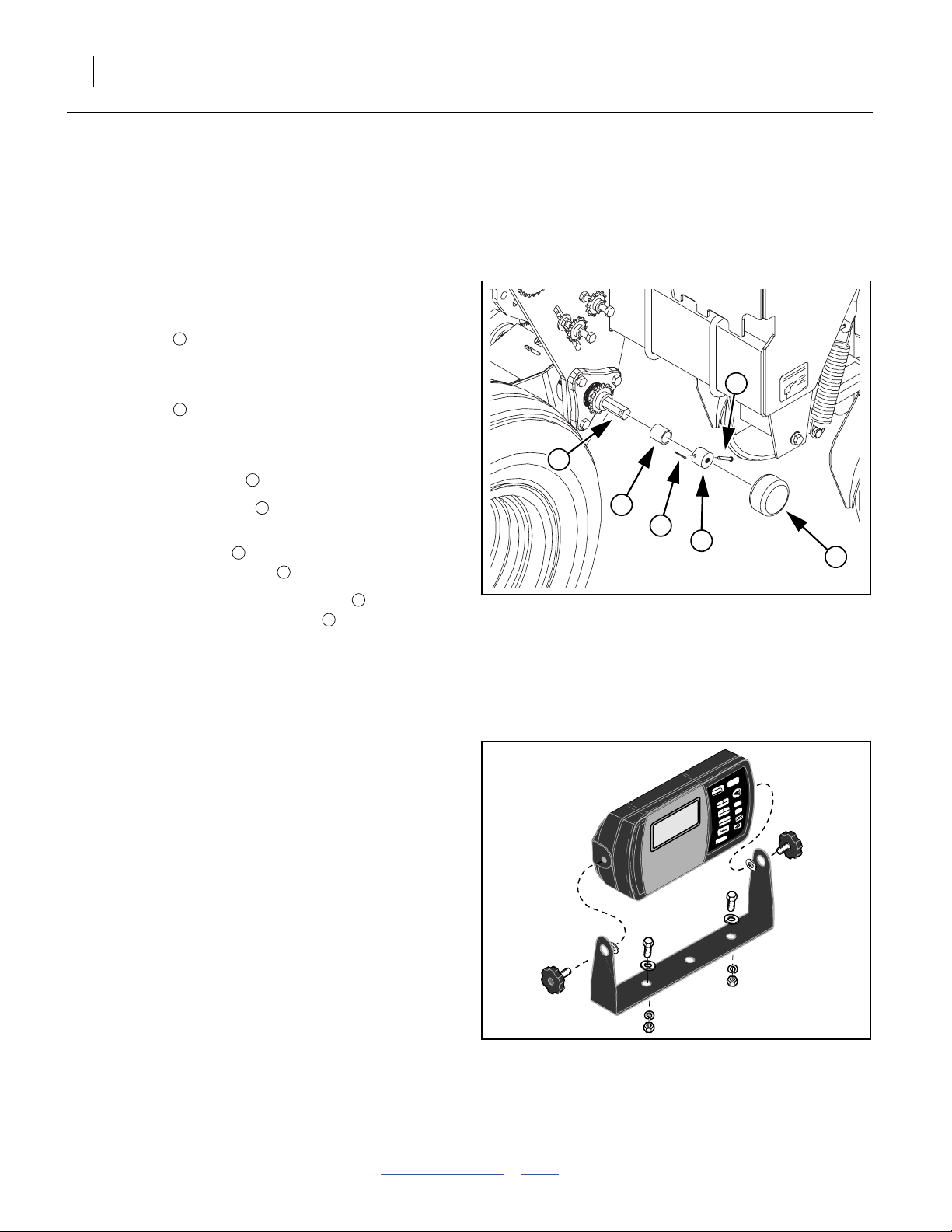
Acremeter Installation
Refer to Figure 19
The acremeter may be supplied from the factory in a
separate carton, to minimize risk of shipping damage.
Check to see if it has already been installed by your
dealer. It is located on the outside end of the upper wheel
arm pivot shaft . It may be installed on either the left or
right gauge wheel.
If not already installed:
1. Slide the spacer tube onto the shaft.
1
5
2
2
3
2. Slide the shaft adaptor onto the shaft, aligning its
cross-pin hole with the hole in the shaft.
3. Insert the clevis pin through the adaptor and shaft
and secure with cotter pin .
4. Screw the threaded end of the meter into the
1
⁄
-20 tapped hole in the adaptor .
2
Tighten the threaded end only enough to prevent it from
working loose from normal vibration. In use, there is no
torque or tension that might tend to unscrew it.
See “Acremeter Operation” on page 30.
4
5
6
1
4
Seed Monitor Cab Module
If your drill has the optional seed monitor, the cab
module may already have been installed by your dealer.
If not, consult the installation instructions included with
the option kit, and mount the module in a convenient
location.
If the cab is particularly noisy, or the operator customarily
wears a noise-cancelling headset, the alarms may not be
audible. Mount the module where the controls and status
indicators are visible during planting operations.
See the separate DICKEY-john manual for initial setup of
the seed monitor.
3
6
4
Figure 19
Acremeter Installation
1
27220
Speed Sensor Installation
The optional seed monitor requires a speed input in
order to determine seeding rate. The sensor is ordered
separately, and may be a magnetic pickup, or a radar,
mounted on the drill or on the tractor. Consult the
documentation supplied with the sensor.
118-245M Table of Contents Index 2013-10-21
Seed Monitor Cab Module
Figure 20
27390
Great Plains Manufacturing, Inc. Table of Contents Index Preparation and Setup 23
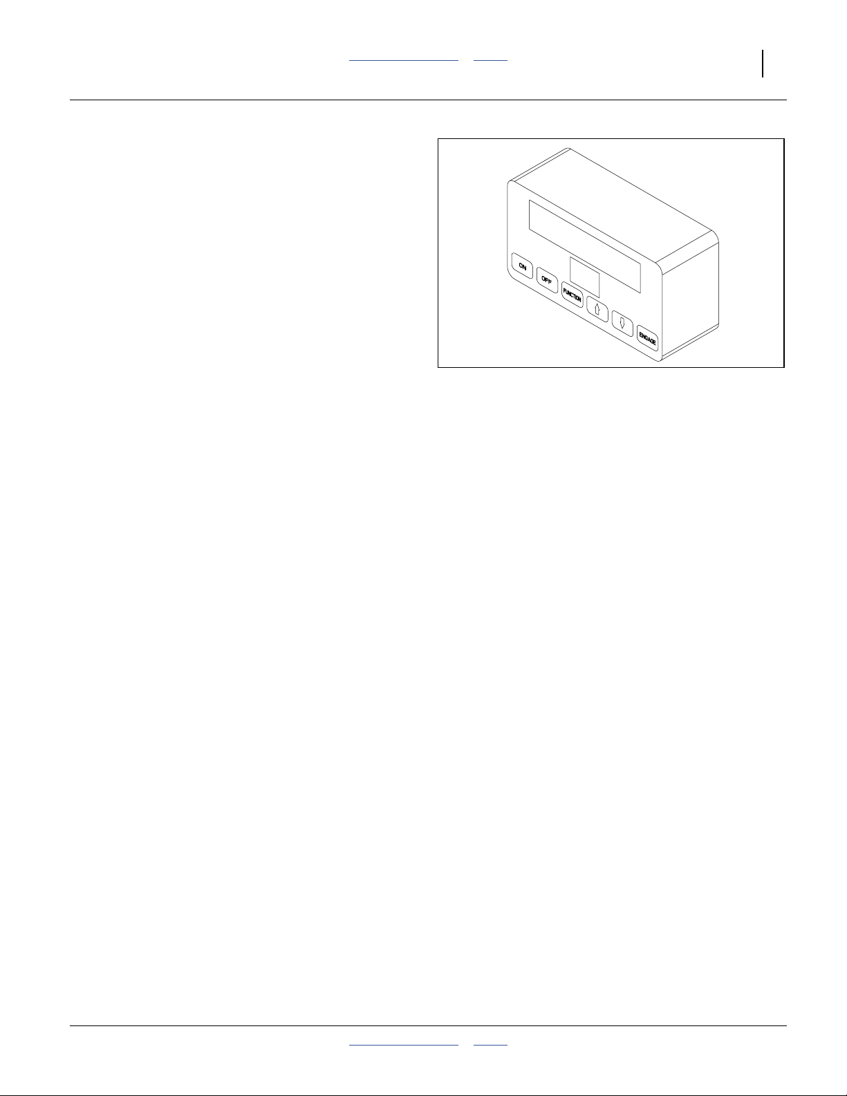
Hydraulic Console Installation
If your drill has the optional hydraulic meter drive, the cab
module may already have been installed by your dealer.
If not, consult the installation instructions included with
the option kit, and mount the module in a convenient
location.
If the cab is particularly noisy, or the operator customarily
wears a noise-cancelling headset, the alarms may not be
audible. Mount the module where the controls and status
indicators are visible during planting operations.
See “Hydraulic Drive Operation” starting on page 68
for initial setup and planting operations.
Figure 21
Hydraulic Drive Cab Module
27392
2013-10-21 Table of Contents Index 118-245M
24 1510HDP/2010HDP/2510HDP Table of Contents Index Great Plains Manufacturing, Inc.
Marker Setup
This section covers markers installed on the drill. For
markers installed on an accessory hitch, consult the
hitch and/or hitch-marker manual. Marker Extension data
in the Appendix of this manual applies to drill- or
hitch-mounted markers.
If drill-mounted markers were ordered as a separate
accessory, or were not dealer-installed, mount them per
the installation instructions supplied with the markers.
Marker Chain Adjustment
There are two, interrelated adjustments for the marker
chain. Make these adjustments in the following order.
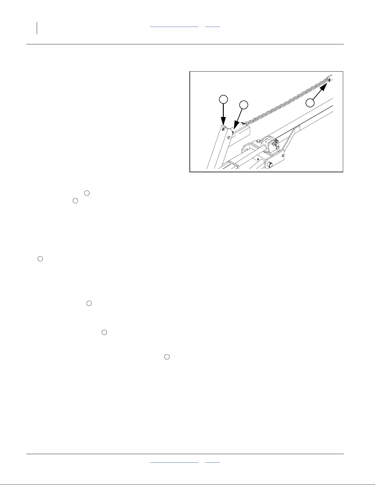
Refer to Figure 22
Marker Lifting Slack
1. Unfold marker.
2. Loosen jam nuts on both sides of channel at
adjuster bolt .
3. Thread bolt in (up) until head is flush with inside jam
nut and both are flush with inside of channel.
4. Slowly fold marker while observing disk. If marker
disk drags across ground more than 12in (30cm)
before lifting, the chain is too long.
5. Shorten chain one or two links by moving clevis bolt
3
up chain a few links. Check adjustment by
repeating folding process.
6. If chain is too short when marker is unfolded, it will
prevent end of marker from dropping into field
depressions, causing skips in your marker line.
Correct this condition by lengthening chain one or
two links at clevis .
Folding Slack
1. Fold marker.
1
2
3
1
2
Figure 22
Marker Chain
3
15669
2. Extend adjustment bolt to take slack out of chain
while marker is folded. Extend bolt until there is no
chain slack.
3. Lock bolt in this position by tightening jam nuts on
either side of upright channel.
118-245M Table of Contents Index 2013-10-21
2
1
Great Plains Manufacturing, Inc. Table of Contents Index Preparation and Setup 25
Marker Extension Setup
Check the marker extension, even if already
dealer-installed. The marker’s own installation
instructions may not have covered setting the correct
marker arm length, or may have specified a length not
optimal for your initial planting.
Refer to Figure 23
Set the initial marker extension to the value for your
row spacing from the Appendix starting at page 136.
Measure from the centerline of the end row unit (outer
unit of a twin pair), whether that row is used or not, to the
mark left in the ground when the drill is lowered.
If you modify your row spacing, this can change the
marker extension required. Some custom row spacing
changes result in an asymmetric row spacing about
machine centerline. This usually causes the marker
extension to be different for left and right sides,
depending on the direction of planting for each
successive pass.
Make short practice passes to confirm correct marker
extension.
E
E
Figure 23
Marker Extension
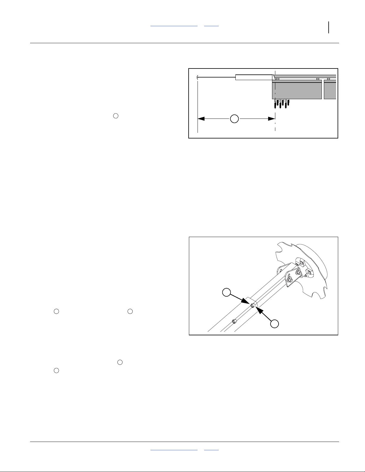
Marker Extension Adjustment
Refer to Figure 24
To adjust a marker width or disk pivot orientation:
1. Lower drill to field position and extend the marker
side to be adjusted.
2. If disk angle or direction is to be changed, make that
change before adjusting extension.
3. Pull forward to fully settle drill and leave a mark to
check.
4. On telescoping outer marker tubes, loosen both jam
1 2
nuts and both
5. Move marker disk tube in or out to get the desired
mark placement. See page 136 for suggested initial
marker extensions, measured from drill centerline.
6. To change throw direction of marker, remove inner
tube completely, and reinsert at desired orientation.
7. Tighten both
1
nuts .
8. Pull forward to check actual results and fold marker.
Other marker topics in this manual include:
“Marker Operations” on page 32
“Marker Disk Angle” on page 66
“Marker Speed” on page 66
1
⁄
in set screws .
2
1
⁄
in set screws and then both jam
2
2
1
2
Figure 24
Marker Extension Adjustment
19204
2013-10-21 Table of Contents Index 118-245M

26 1510HDP/2010HDP/2510HDP Table of Contents Index Great Plains Manufacturing, Inc.
Operating Instructions
This section covers general operating procedures.
Experience, machine familiarity and the following
information will lead to efficient operation and good
working habits. Always operate farm machinery with
safety in mind.
Pre-Start Checklist
1. Carefully read “Important Safety Information”
starting on page 1.
2. Lubricate drill as indicated in “Lubrication” starting
on page 116.
3. Check all tires for proper inflation. See “Tire
Inflation Chart” on page 135.
4. Check all bolts, pins and fasteners. Torque as shown
in “Torque Values Chart” on page 136.
5. Check drill for worn or damaged parts. Repair or
replace parts before going to the field.
6. Check any hydraulic hoses, fittings and cylinders for
leaks. Repair or replace before going to the field.
Prepare for Planting
7. Install meters and seed wheels for the intended crop.
See “Meter Adjustments” on page 58.
8. For ground drive, rotate both gauge wheels to see
that the drive and meters are working properly and
free from foreign material.
9. To reduce wear, remove chains for drive systems
that will not be used at present. See page 166 for
chain diagrams.
10. Using the Seed Rate charts, perform the initial setup
of the material rates. See page 35.
11. Turn on the seed monitor (if installed), and configure
it for the materials, row spacing and intended
population. See separate DICKEY-john manual.
12. Turn on the hydraulic drive controller (if installed),
and configure it for the population intended. See
“Hydraulic Drive Operation” starting on page 68.
13. Unless rate checking or calibration will be performed
in the field to be planted, verify or calibrate rates.
See page 38, 40 or 46.
Escaping fluid under pressure can have sufficient pressure to
penetrate the skin. Check all hydraulic lines and fittings before
applying pressure. Fluid escaping from a very small hole can
be almost invisible. Use paper or cardboard, not body parts,
and wear heavy gloves to check for suspected leaks. If injured,
seek medical assistance from a doctor that is familiar with this
type of injury. Hydraulic fluid injected under the skin is an
extremely serious matter. If such an accident occurs, seek
urgent medical attention from a physician familiar with this
type of injury.
118-245M Table of Contents Index 2013-10-21
 Loading...