

Page 1
Great Plains Mfg., Inc.
Installation Instructions
20P, 24P, 25P 3-Point Precision Drills
20F and 24F 3-Point Drills
Weight Bracket Kit
Used with:
• 20P 3-Point Precision Seeding System
• 24P 3-Point Precision Seeding System
• 25P 3-Point Precision Seeding System
• 20F 3-Point Drill
• 24F 3-Point Drill
General Information
When you see this symbol, the subsequent instructions and
warnings are serious - follow without exception. Your life
!
!
and the lives of others depend on it!
These instructions explain how to install the Weight
Bracket Kit. This optional kit is used to add weight to
the drill frame.These instructions apply to:
118-071A 20P/24P/25P Weight Bracket Kit
118-072A 20F and 24F Weight Bracket Kit
Assembly Instructions for 118-071A
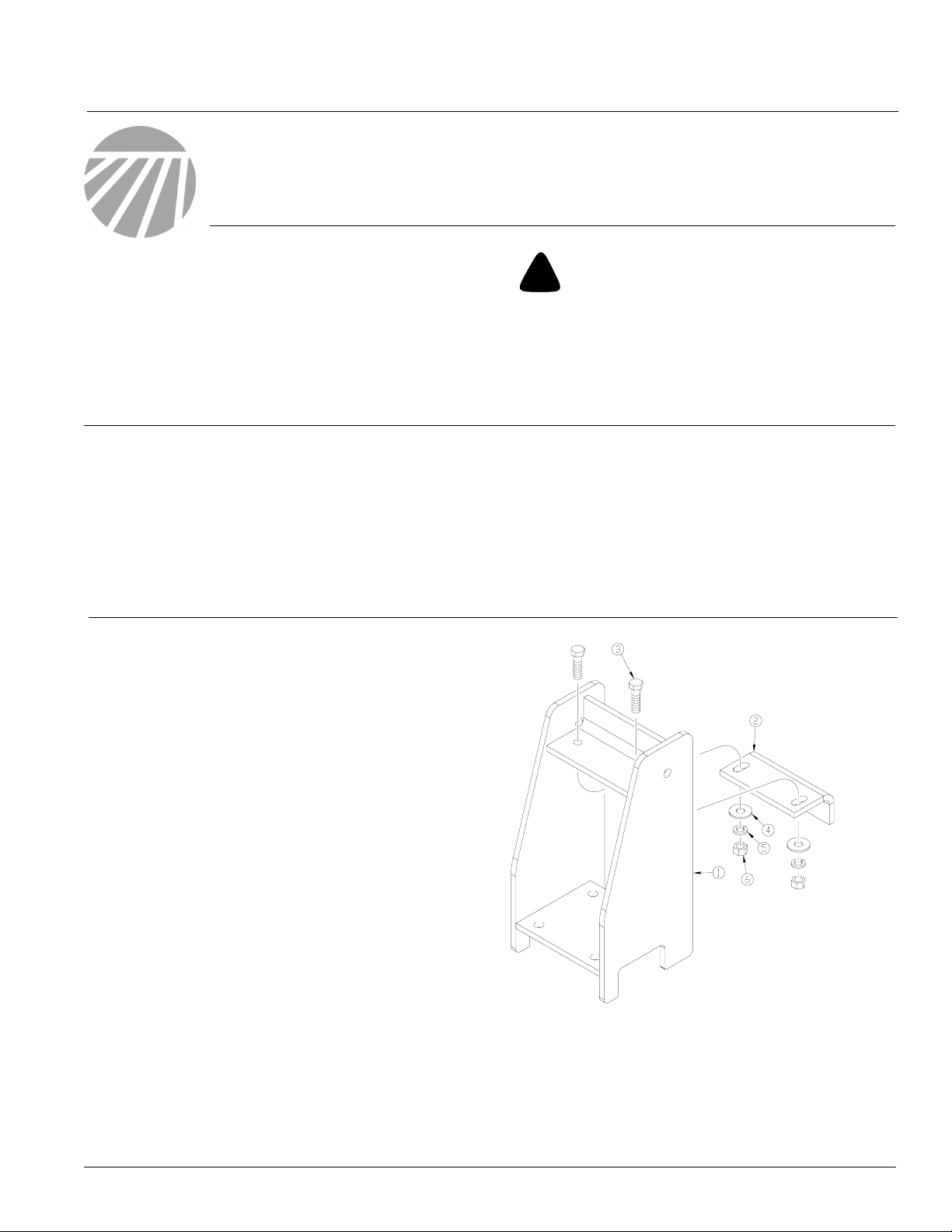
Refer to Figure 1
1. Attach weight bracket adjustment leg (2) to
weight bracket weldment (1).
2. Secure adjustment leg (2) to weldment (1) using two 5/8-11 x 2 1/4 bolts (3), 5/8 flat washers
(4), 5/8 lock washers (5), and 5/8-11 hex nuts
(6). Leave bolts loosened for adjustment.
3. Complete steps one and two for both weight
brackets.
Before You Start
Page 5 is a detailed listing of parts included in the
Weight Bracket Kit. Use this list to inventory parts
received.
Tools Required
• Basic Hand Tools
© Copyright 2006 Printed
4/5/2006
24443
Figure 1
Weight Bracket and Adjustment Leg
118-073M
Page 2
Weight Bracket Kit
2
Great Plains Mfg., Inc.
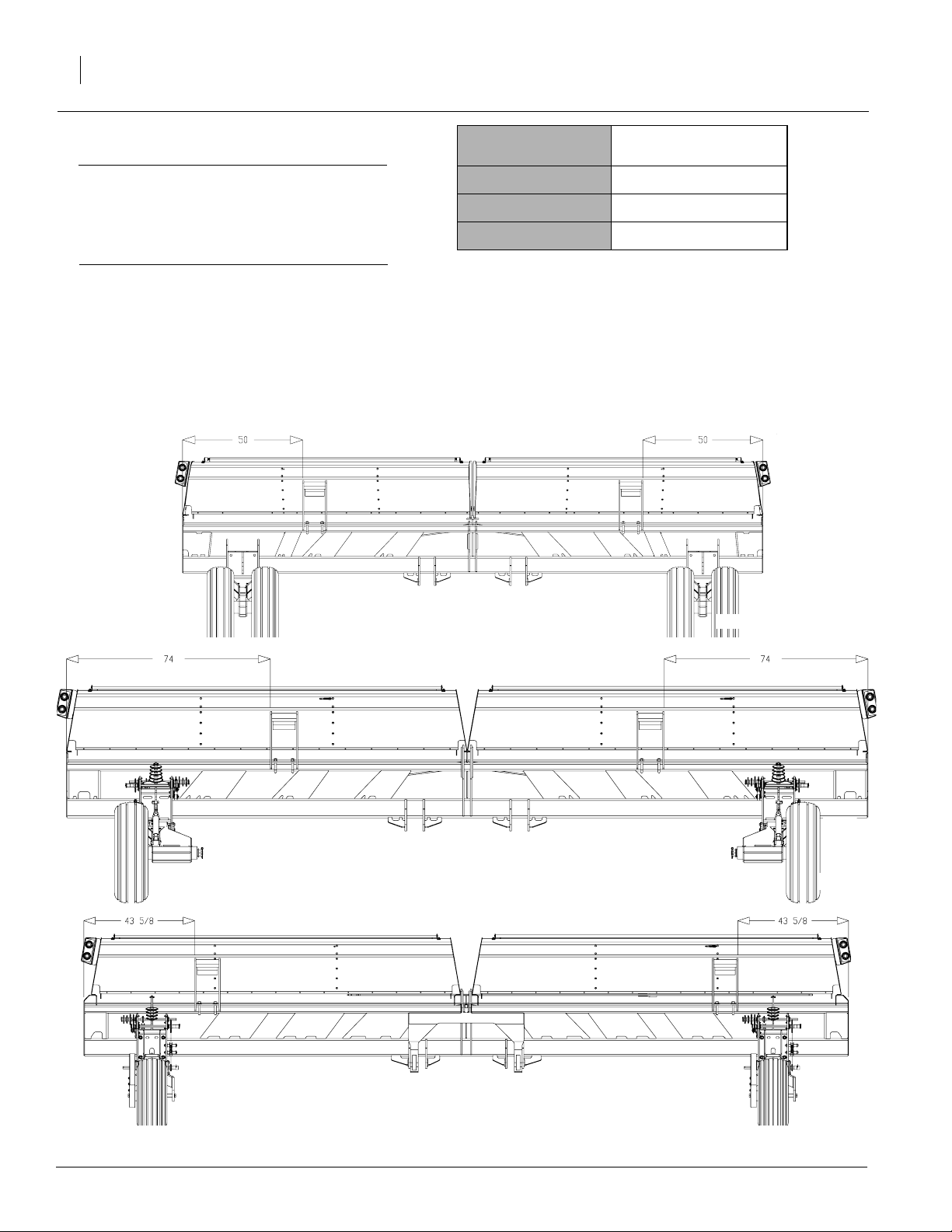
Refer to Table 1
IMPORTANT! The chart to the right gives the recommended placement for LH and RH weight brackets. However, weight brackets may be placed
anywhere along frame provided there are no clearance issues.
4. For both LH and RH brackets, measure the distance given in the chart for the appropriate drill
model. NOTE: Measure distance from each end
of drill frame towards center of drill.
Refer to Figure 2
5. Place weight bracket on drill frame.
Drill Model Distance From End of Drill
Frame
20P 50 inches
24P 74 inches
25P 43 5/8 inches
Table 1
20P Weight Bracket Layout
24P Weight Bracket Layout
24448
24447
25P Weight Bracket Layout
Figure 2
Weight Bracket Placement
118-073M 4/5/2006
24439
Page 3

Great Plains Mfg., Inc.
Refer to Figure 3
6. Secure weight bracket (1) to frame (3) using
two 3/4-10 x 5 1/32 x 4 u-bolts (2), 3/4 lock
washers (5), and 3/4-10 hex nuts (4).
7. Position adjustment leg (6) against weight edge
for additional support. Tighten bolts securing
adjustment leg to weight bracket.
8. Complete steps 5 through 8 for both weight
brackets.
Installation Instructions
Figure 3
Secure Weight Bracket to Frame
3
24446
Assembly Instructions for 118-072A
NOTE: The 20F and 24F Weight Bracket Kit
comes with specific LH and RH weight brackets.
Refer to Figure 1
1. Attach weight bracket adjustment leg (2) to
both LH and RH weight bracket weldments (1).
2. Secure adjustment leg (2) to weldment (1) using two 5/8-11 x 2 1/4 bolts (3), 5/8 flat washers
(4), 5/8 lock washers (5), and 5/8-11 hex nuts
(6). Leave bolts loosened for adjustment.
Refer to Table 1
IMPORTANT! The chart to the right gives the
recommended placement for LH and RH weight
brackets. However, weight brackets may be
placed anywhere along frame provided there
are no clearance issues.
24445
Figure 1
Weight Bracket and Adjustment Leg
Drill Model Distance From End of Drill
Frame
20F 55 1/2 inches
3. For both LH and RH weight brackets, measure
the distance given in the chart for the appropriate drill model. NOTE: Measure distance
from each end of drill frame towards center
of drill.
4/5/2006
24F 50 1/2 inches
Table 1
118-073M
Page 4

Weight Bracket Kit
4
Refer to Figure 2
4. Determine which weight bracket is LH
bracket and which is RH bracket. NOTE:
There is a cut-out notch on one side of
each bracket. The notched side goes
toward center of drill to allow clearance
for frame brace.
5. Place LH bracket on LH-side drill frame.
Place RH bracket on RH-side drill frame.
Great Plains Mfg., Inc.
20F Weight Bracket Layout
24F Weight Bracket Layout
Weight Bracket Placement
Refer to Figure 3
6. Secure weight bracket (1) to frame (2) using u-bolts (3 and 4), 3/4 lock washers (6),
and 3/4-10 hex nuts (5).
NOTE: Use longer u-bolt (3) to secure
frame (2) to raised portion of bottom of
weight bracket (1).
7. Position adjustment leg (7) against weight
edge for additional support. Tighten bolts
securing adjustment leg to bracket.
8. Complete steps 5 through 8 for both
weight brackets.
24440
24449
Figure 2
24444
Figure 3
Secure Weight Bracket to Frame
118-073M 4/5/2006
Page 5

Great Plains Mfg., Inc.
118-071A 20P/24P/25P Weight Bracket Kit
Your kit includes:
Qty. Part No. Part Description
2 118-068H WEIGHT BRACKET WELDMENT
2 197-062D WEIGHT BRACKET ADJ LEG
4 802-057C HHCS 5/8-11 X 2 1/4 GR5
4 803-021C NUT HEX 5/8-11 PLT
8 803-027C NUT HEX 3/4-10 PLT
4 804-019C WASHER FLAT 5/8 USS PLT
4 804-022C WASHER LOCK SPRING 5/8 PLT
8 804-023C WASHER LOCK SPRING 3/4 PLT
4 806-203C U-BOLT 3/4-10 X 5 1/32 X 4
1 118-073M MANUAL WEIGHT BRACKET
Installation Instructions
5
118-072A 20F and 24F Weight Bracket Kit
Your kit includes:
Qty. Part No. Part Description
1 118-069H WEIGHT BRACKET WELDMENT-LH
1 118-070H WEIGHT BRACKET WELDMENT-RH
2 197-062D WEIGHT BRACKET ADJ LEG
4 802-057C HHCS 5/8-11 X 2 1/4 GR5
4 803-021C NUT HEX 5/8-11 PLT
8 803-027C NUT HEX 3/4-10 PLT
4 804-019C WASHER FLAT 5/8 USS PLT
4 804-022C WASHER LOCK SPRING 5/8 PLT
8 804-023C WASHER LOCK SPRING 3/4 PLT
2 806-089C U-BOLT 3/4-10 X 6 1/16 X 9
2 806-093C U-BOLT 3/4-10 X 6 1/32 X 7 3/4
1 118-073M MANUAL WEIGHT BRACKET
118-073M4/5/2006
 Loading...