

Page 1
Operator’s Manual
1520F, 2020F, 2420F, 1510HDF, & 2010HDF
15’, 20’, and 24’ 3-Point Drills
Manufacturing, Inc.
www.greatplainsmfg.com
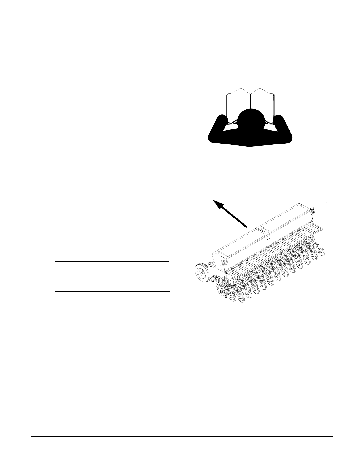
Read the operator’s manual entirely. When you see this symbol, the subsequent
instructions and warnings are serious - follow without exception. Your life and
!
the lives of others depend on it!
24137
Cover illustration may show optional equipment not supplied with standard unit.
© Copyright 2006 Printed 2/28/2006
288-196M
Page 2

Table of Contents
Important Safety Information . . . . . . . . . . . . . . . . 1
Safety Decals . . . . . . . . . . . . . . . . . . . . . . . . . . 7
Introduction . . . . . . . . . . . . . . . . . . . . . . . . . . . . . 12
Description of Unit . . . . . . . . . . . . . . . . . . . . . 12
Intended Usage . . . . . . . . . . . . . . . . . . . . 12
Models Covered in this Manual . . . . . . . . 12
Using This Manual . . . . . . . . . . . . . . . . . . . . . 13
Definitions . . . . . . . . . . . . . . . . . . . . . . . . 13
Owner Assistance. . . . . . . . . . . . . . . . . . . . . . 14
Preparation and Setup . . . . . . . . . . . . . . . . . . . . 15
Prestart Checklist . . . . . . . . . . . . . . . . . . . . . . 15
Hitching Tractor to Drill . . . . . . . . . . . . . . . . . . 15
Hydraulic Hose Hookup . . . . . . . . . . . . . . 16
Leveling the Drill . . . . . . . . . . . . . . . . . . . . . . . 17
Operating Instructions . . . . . . . . . . . . . . . . . . . . 21
Prestart Checklist . . . . . . . . . . . . . . . . . . . . . . 21
Field Operation . . . . . . . . . . . . . . . . . . . . . . . . 22
Opener Operation . . . . . . . . . . . . . . . . . . 23
Marker Operation . . . . . . . . . . . . . . . . . . . 23
Transporting . . . . . . . . . . . . . . . . . . . . . . . . . . 23
Transporting with Markers . . . . . . . . . . . . 24
Parking . . . . . . . . . . . . . . . . . . . . . . . . . . . . . . 24
Adjustments . . . . . . . . . . . . . . . . . . . . . . . . . . . . 25
Side Gauge Wheels for 20 Series Openers . . 25
20 Series Openers . . . . . . . . . . . . . . . . . . . . . 26
Opener Down Pressure . . . . . . . . . . . . . . 26
Opener Seeding Depth . . . . . . . . . . . . . . 27
Press Wheel. . . . . . . . . . . . . . . . . . . . . . . 27
Seed-Lok Lock Up . . . . . . . . . . . . . . . . . . . . . 28
HD 10 Series Openers . . . . . . . . . . . . . . . . . . 29
Opener Down Pressure . . . . . . . . . . . . . . 29
Spring Down Pressure . . . . . . . . . . . . . . . 30
Opener Seeding Depth . . . . . . . . . . . . . . 30
Double V Press Wheel Adjustment . . . . . 31
Lock-Up . . . . . . . . . . . . . . . . . . . . . . . . . . 32
Frame Height . . . . . . . . . . . . . . . . . . . . . . . . . 33
Single Gauge Wheel . . . . . . . . . . . . . . . . 33
Dual Gauge Wheels . . . . . . . . . . . . . . . . . 33
Seeding Rate . . . . . . . . . . . . . . . . . . . . . . . . . 34
Adjust Drive Sprockets . . . . . . . . . . . . . 34
Set Seed Rate Handle . . . . . . . . . . . . . 34
Position Seed Cup Doors . . . . . . . . . . . 35
Check Seeding Rate . . . . . . . . . . . . . . . 35
Tire Revolutions Per Acre . . . . . . . . . . . . . . 36
Seed Rate Chart (pounds per acre) . . . . . . 37
Marker Adjustments. . . . . . . . . . . . . . . . . . . 40
Bleeding Marker Hydraulics . . . . . . . . . 40
Folding Speed with Needle Valves . . . . 41
Folding Speed with Sequence Valve. . . 41
Marker Disk Adjustment . . . . . . . . . . . . 41
Changing disk angle . . . . . . . . . . . . . . . 41
Marker Chain. . . . . . . . . . . . . . . . . . . . . 42
Transport Carrier . . . . . . . . . . . . . . . . . . 42
Marker Width. . . . . . . . . . . . . . . . . . . . . 43
Seed-Lok™ Lock Up . . . . . . . . . . . . . . . . . . 44
Troubleshooting. . . . . . . . . . . . . . . . . . . . . . . . 45
Maintenance and Lubrication . . . . . . . . . . . . . 47
Maintenance . . . . . . . . . . . . . . . . . . . . . . . . 47
Storage . . . . . . . . . . . . . . . . . . . . . . . . . . . . 51
Lubrication . . . . . . . . . . . . . . . . . . . . . . . . . . 52
Options . . . . . . . . . . . . . . . . . . . . . . . . . . . . . . . 54
Appendix. . . . . . . . . . . . . . . . . . . . . . . . . . . . . . 56
Torque Values Chart . . . . . . . . . . . . . . . . . . 56
Tire Inflation Chart . . . . . . . . . . . . . . . . . . . . 57
Specifications and Capacities . . . . . . . . . . . 57
Sprocket Configuration . . . . . . . . . . . . . . . . 58
Warranty . . . . . . . . . . . . . . . . . . . . . . . . . . . 61
© Copyright 2005 All rights Reserved
Great Plains Manufacturing, Inc. provides this publication “as is” without warranty of any kind, either express or implied. While every precaution has been taken in the
preparation ofthis manual,Great PlainsManufacturing, Inc.assumes noresponsibility for errors or omissions. Neither is any liability assumed fordamages resultingfrom
the use of the information contained herein. GreatPlains Manufacturing, Inc. reserves theright to revise and improve its products as it sees fit. Thispublication describes
the state of this product at the time of its publication, and may not reflect the product in the future.
The following are trademarks of Great Plains Mfg., Inc.: Application Systems, Ausherman, Land Pride, Great Plains
All other brands and product names are trademarks or registered trademarks of their respective holders.
8/14/2006
Great Plains Manufacturing, Incorporated Trademarks
Printed in the United States of America.
Page 3
Important Safety Information
Look for Safety Symbol
The SAFETY ALERT SYMBOL indicates there is
a potential hazard to personal safety involved and
extra safety precaution must be taken. When you
see this symbol, be alert and carefully read the
message that follows it. In addition to design and
configuration of equipment, hazard control and
accident prevention are dependent upon the
awareness, concern, prudence and proper training of personnel involved in the operation,
transport, maintenance and storage of
equipment.
Important Safety Information
!
1
Be Aware of Signal Words
Signal words designate a degree or level of hazard seriousness.
DANGER indicates an imminently hazardous situation which, if not avoided, will result in death or
serious injury. This signal word is limited to the
most extreme situations, typically for machine
components that, for functional purposes, cannot
be guarded.
WARNING indicates a potentially hazardous situation which, if not avoided, could result in death or
serious injury, and includes hazards that are exposed when guards are removed. It may also be
used to alert against unsafe practices.
CAUTION indicates a potentially hazardous situation which, if not avoided, may result in minor or
moderate injury. It may also be used to alert
against unsafe practices.
DANGER
!
WARNING
!
CAUTION
!
8/14/2006
Page 4
1520F, 2020F, 2420F, 1510HDF, &
2
2010HDF
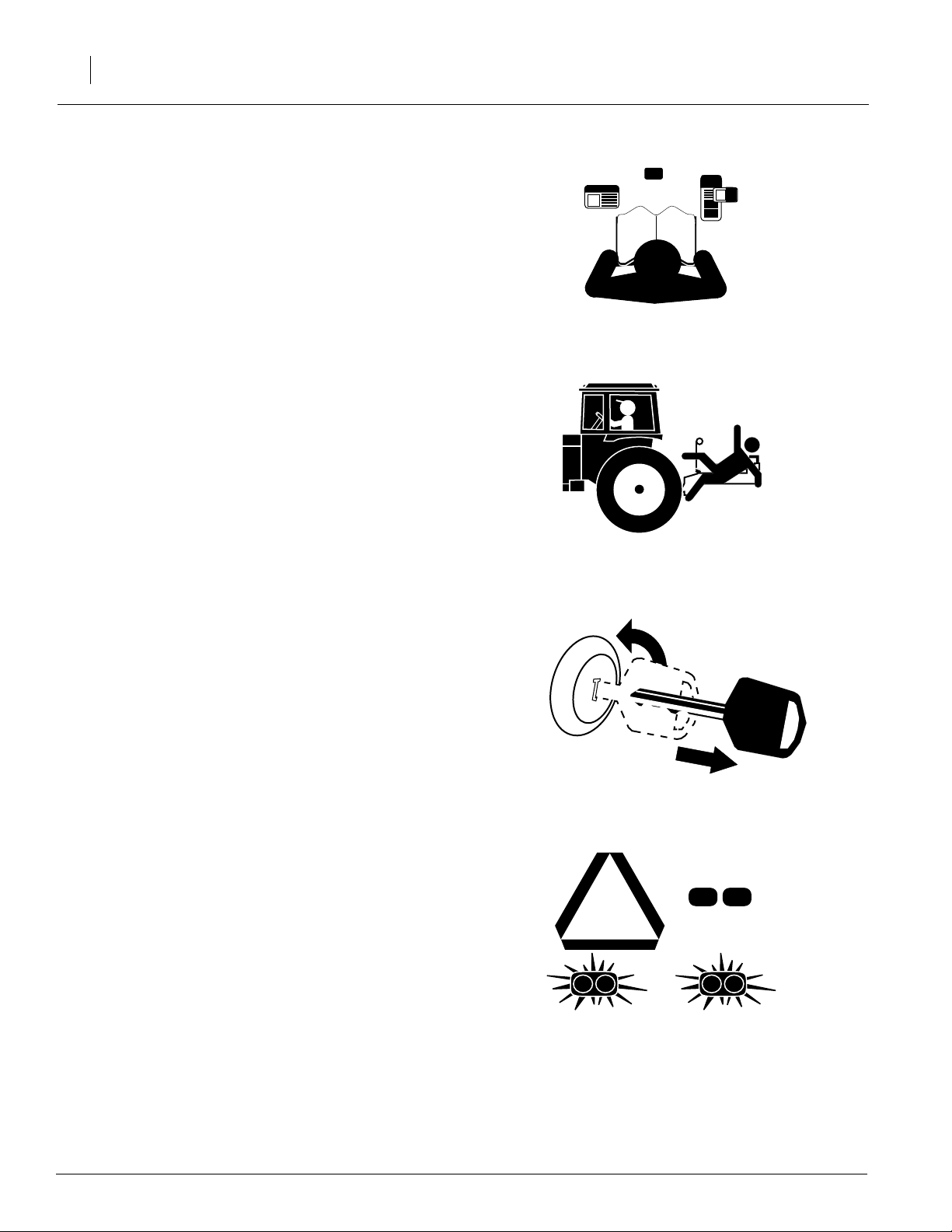
Be Familiar with Safety Decals
▲ Read and understand “Safety Decals,” page 7,
thoroughly.
▲ Read all instructions noted on the decals.
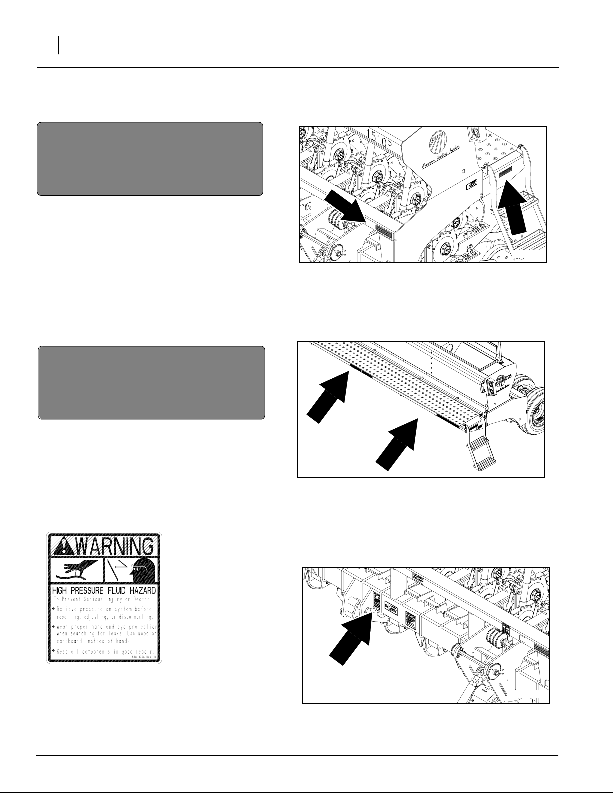
Keep Riders Off Machinery
Riders obstruct the operator’s view. Riders could
be struck by foreign objects or thrown from the
machine.
▲ Never allow children to operate equipment.
▲ Keep all bystanders away from machine dur-
ing operation.
Shutdown and Storage
▲ Lower drill, put tractor in park, turn off engine,
and remove the key.
▲ Secure drill using blocks and supports pro-
vided.
▲ Detach and store drill in an area where chil-
dren normally do not play.
Use Safety Lights and Devices
Slow-moving tractors and towed implements can
create a hazard when driven on public roads.
They are difficult to see, especially at night.
▲ Use flashing warning lights and turn signals
whenever driving on public roads.
▲ Use lights and devices provided with imple-
ment.
OFF
8/14/2006
Page 5
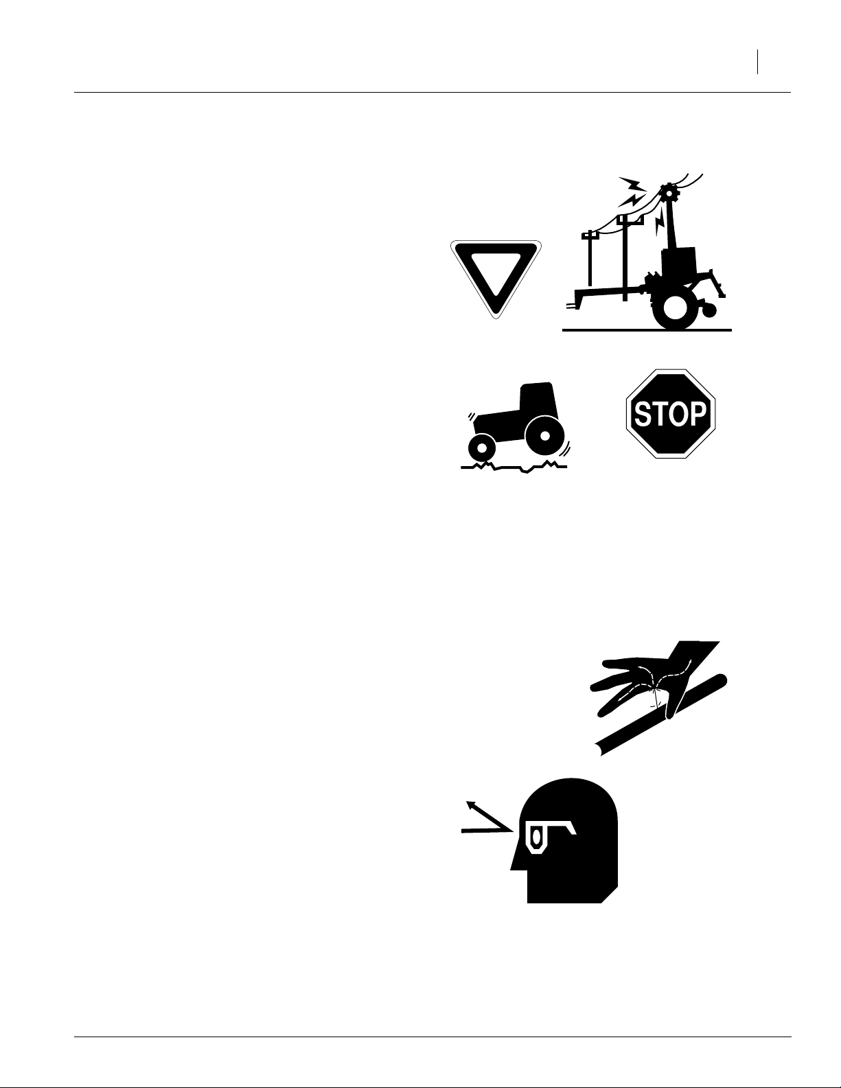
Transport Machinery Safely
Maximum transport speed for implement is 20
mph. Some rough terrains require a slower
speed. Sudden braking can cause a towed load to
swerve and upset.
▲ Do not exceed 20 mph. Never travel at a
speed which does not allow adequate control
of steering and stopping. Reduce speed if
towed load is not equipped with brakes.
▲ Comply with state and local laws.
▲ Do not tow an implement that, when fully
loaded, weighs more than 1.5 times the weight
of towing vehicle.
▲ Carry reflectors or flags to mark drill in case of
breakdown on the road.
▲ Keep clear of overhead power lines and other
obstructions when transporting.
Important Safety Information
3
Avoid High Pressure Fluids
Escaping fluid under pressure can penetrate the
skin, causing serious injury.
▲ Avoid the hazard by relieving pressure before
disconnecting hydraulic lines.
▲ Use a piece of paper or cardboard, NOT
BODY PARTS, to check for suspected leaks.
▲ Wear protective gloves and safety glasses or
goggles when working with hydraulic systems.
▲ If an accident occurs, see a doctor immedi-
ately. Any fluid injected into the skin must be
surgically removed within a few hours or gangrene may result.
8/14/2006
Page 6

1520F, 2020F, 2420F, 1510HDF, &
4
2010HDF
Practice Safe Maintenance
▲ Understand procedure before doing work. Use
proper tools and equipment. Refer to this manual for additional information.
▲ Work in a clean, dry area.
▲ Lower the drill, put tractor in park, turn off
engine, and remove key before performing
maintenance.
▲ Make sure all moving parts have stopped and
all system pressure is relieved.
▲ Allow drill to cool completely.
▲ Disconnect battery ground cable (-) before
servicing or adjusting electrical systems or
before welding on drill.
▲ Inspect all parts. Make sure parts are in good
condition and installed properly.
▲ Remove buildup of grease, oil or debris.
▲ Remove all tools and unused parts from drill
before operation.
Prepare for Emergencies
▲ Be prepared if a fire starts.
▲ Keep a first aid kit and fire extinguisher handy.
OFF
▲ Keep emergency numbers for doctor, ambu-
lance, hospital and fire department near
phone.
Wear Protective Equipment
▲ Wear protective clothing and equipment.
▲ Wear clothing and equipment appropriate for
the job. Avoid loose-fitting clothing.
▲ Because prolonged exposure to loud noise
can cause hearing impairment or hearing loss,
wear suitable hearing protection such as earmuffs or earplugs.
▲ Because operating equipment safely requires
your full attention, avoid wearing radio headphones while operating machinery.
911
8/14/2006
Page 7
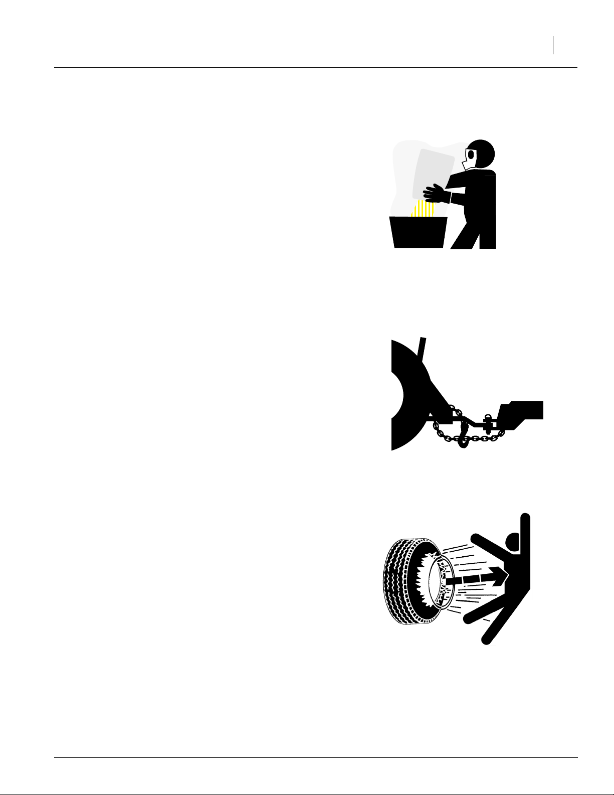
Handle Chemicals Properly
Agricultural chemicals can be dangerous. Improper use can seriously injure persons, animals,
plants, soil and property.
▲ Read and follow chemical manufacturer’s
instructions.
▲ Wear protective clothing.
▲ Handle all chemicals with care.
▲ Avoid inhaling smoke from any type of chemi-
cal fire.
▲ Store or dispose of unused chemicals as
specified by chemical manufacturer.
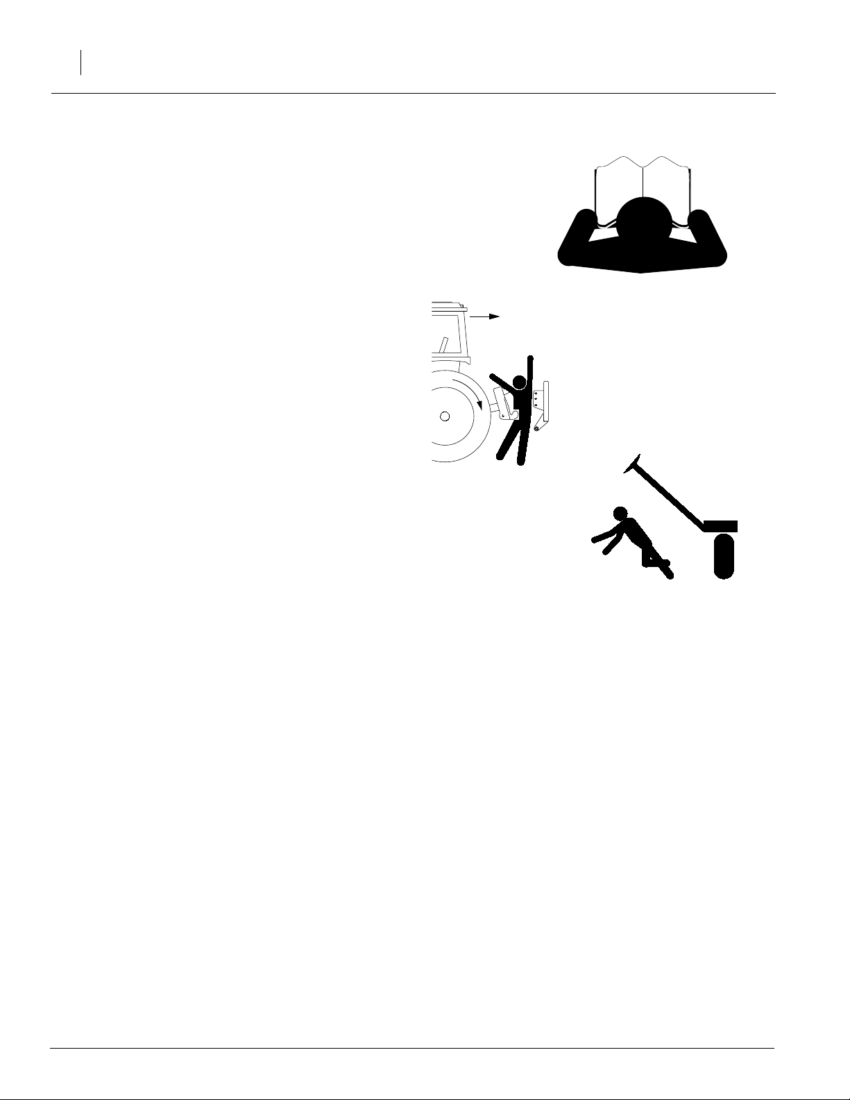
Use A Safety Chain
▲ Use a safety chain to help control drawn
machinery should it separate from tractor
drawbar.
Important Safety Information
5
▲ Use a chain with a strength rating equal to or
greater than the gross weight of towed
machinery.
▲ Attach chain to tractor drawbar support or
other specified anchor location. Allow only
enough slack in chain to permit turning.
▲ Replace chain if any links or end fittings are
broken, stretched or damaged.
▲ Do not use safety chain for towing.
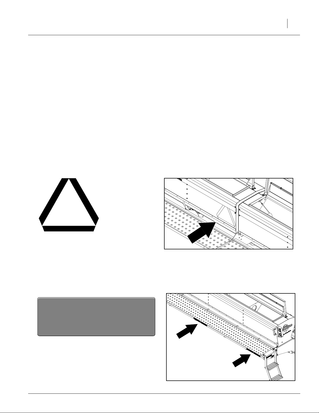
Tire Safety
Tire changing can be dangerous and should be
performed by trained personnel using correct
tools and equipment.
▲ When inflating tires, use a clip-on chuck and
extension hose long enough for you to stand
to one side–not in front of or over tire assembly. Use a safety cage if available.
▲ When removing and installing wheels, use
wheel-handling equipment adequate for
weight involved.
8/14/2006
Page 8
1520F, 2020F, 2420F, 1510HDF, &
6
2010HDF
Safety At All Times
Thoroughly read and understand the instructions
in this manual before operation. Read all instructions noted on the safety decals.
▲ Be familiar with all drill functions.
▲ Operate machinery from the driver’s seat only.
▲ Do not leave drill unattended with tractor
engine running.
▲ Do not dismount a moving tractor. Dismount-
ing a moving tractor could cause serious injury
or death.
▲ Do not stand between the tractor and drill dur-
ing hitching.
▲ Keep hands, feet and clothing away from
power-driven parts.
▲ Wear snug-fitting clothing to avoid entangle-
ment with moving parts.
▲ Watch out for wires, trees, etc., when folding
markers or raising drill. Make sure all persons
are clear of working area.
▲ Do not turn tractor too tightly, causing drill to
ride up on wheels. This could cause personal
injury or equipment damage.
8/14/2006
Page 9
Important Safety Information
7
Safety Decals
Your implement comes equipped with all safety
decals in place. They were designed to help you
safely operate your implement.
▲ Read and follow decal directions.
▲ Keep all safety decals clean and legible.
▲ Replace all damaged or missing decals. Order
new decals from your Great Plains dealer.
Refer to this section for proper decal placement.
▲ When ordering new parts or components, also
request corresponding safety decals.
▲ To install new decals:
1. Clean the area on which the decal is to be
placed.
2. Peel backing from decal. Press firmly on
surface, being careful not to cause air
bubbles under decal.
818-003C
818-003C
Slow Moving Vehicle Label
Slow Moving Vehicle Label
838-266C
Red Reflectors
Reflectors on outside ends and off center of walkboards; four reflectors total.
17769
19189
8/14/2006
Page 10
1520F, 2020F, 2420F, 1510HDF, &
8
2010HDF
838-265C
Amber Reflectors
Reflector on both ends of drill; four reflectors total.
18262
838-267C
Decal Reflectors Daytime
Reflectors on inside ends and off center on walkboards next to red reflectors; four reflectors total.
818-339C
High Pressure Hazard
19189
18262
8/14/2006
Page 11
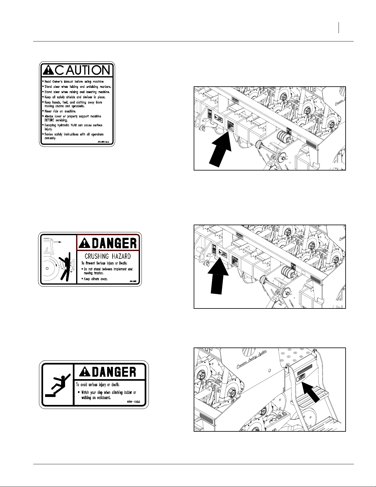
818-587C
General Instructions
Important Safety Information
18262
9
818-590C
Crushing Hazard
838-102C
Falling Hazard
8/14/2006
1826218262
19195
Page 12
1520F, 2020F, 2420F, 1510HDF, &
10
2010HDF
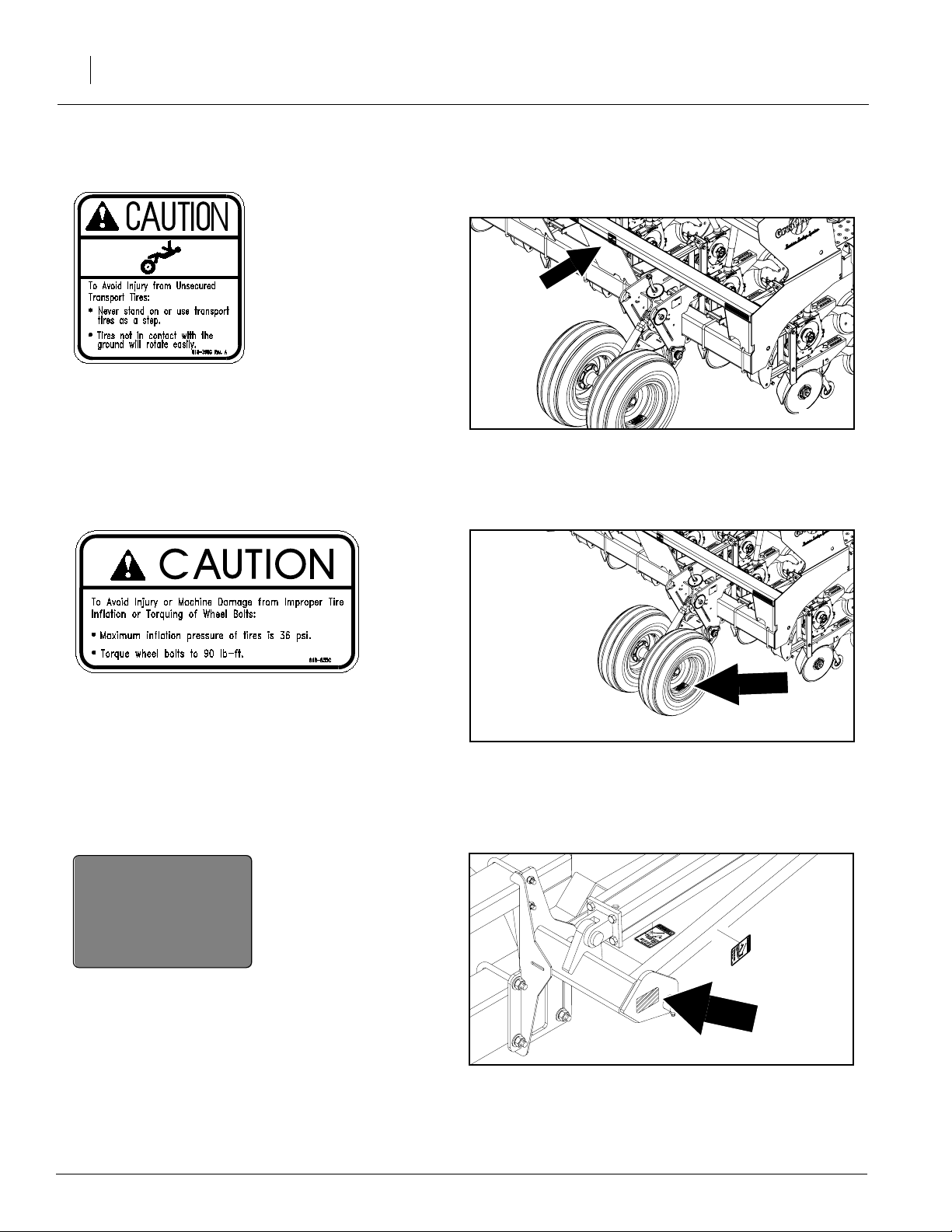
818-398C
Falling Hazard
19197
818-855C
Tire Pressure
818-229C
Amber Reflector
Reflector on each optional marker.
19197
18270
8/14/2006
Page 13
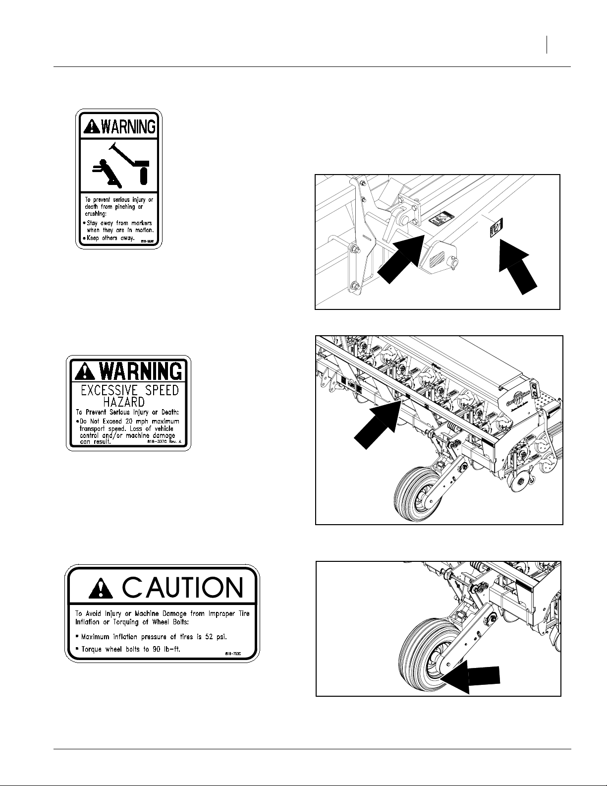
818-682C
7
Crushing Hazard
Two decals on first section of each optional marker;
four decals total.
Important Safety Information
1827018270
11
818-337C
Excessive Speed Hazard
818-752C
Tire Pressure
8/14/2006
182
21641
21641
Page 14
1520F, 2020F, 2420F, 1510HDF, &
12
2010HDF
Introduction
Great Plains welcomes you to its growing family of
new product owners. This drill has been designed
with care and built by skilled workers using quality
materials. Proper setup, maintenance and safe
operating practices will help you get years of satisfactory use from the machine.
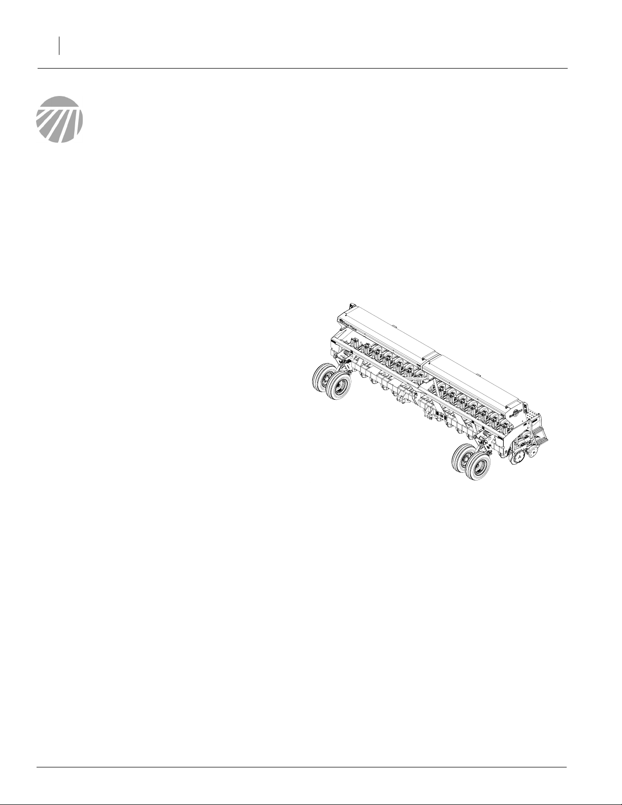
Description of Unit
The 15 ft, 20 ft, and 24 ft 3-point drills are
equipped with HD 10 Series and 20 Series openers. The HD 10 Series Opener is outfitted with
heavy duty parallel-arm openers. The 20 Series
Opener is outfitted with side-depth-control openers. These openers are staggered for easy
residue flow. Opener depth can be adjusted.
Intended Usage
Use the drill to seed production-agriculture crops
only. Do not modify the drill for use with attachments other than Great Plains options and
accessories specified for use with the drill.
Models Covered in this Manual
1520F, 2020F, 2420F, 1510HDF, & 2010HDF
24137
8/14/2006
Page 15
Using This Manual
This manual will familiarize you with safety, assembly, operation, adjustments, troubleshooting
and maintenance. Read this manual and follow
the recommendations to help ensure safe and efficient operation.
The information in this manual is current at printing. Some parts may change to assure top
performance.
Definitions
The following terms are used throughout this
manual.
Machine travel
direction
Introduction
Right-hand
side
13
Refer to Figure 1
Right-hand and left-hand as used in this manual
are determined by facing the direction the machine will travel while in use unless otherwise
stated.
IMPORTANT: A crucial point of information related to the preceding topic. For safe and correct operation, read and follow the directions
provided before continuing.
NOTE: Useful information related to the preceding topic.
Left-hand
side
Figure 1
18327
8/14/2006
Page 16
1520F, 2020F, 2420F, 1510HDF, &
14
2010HDF
Owner Assistance
If you need customer service or repair parts, contact a Great Plains dealer. They have trained
personnel, repair parts and equipment specially
designed for Great Plains products.
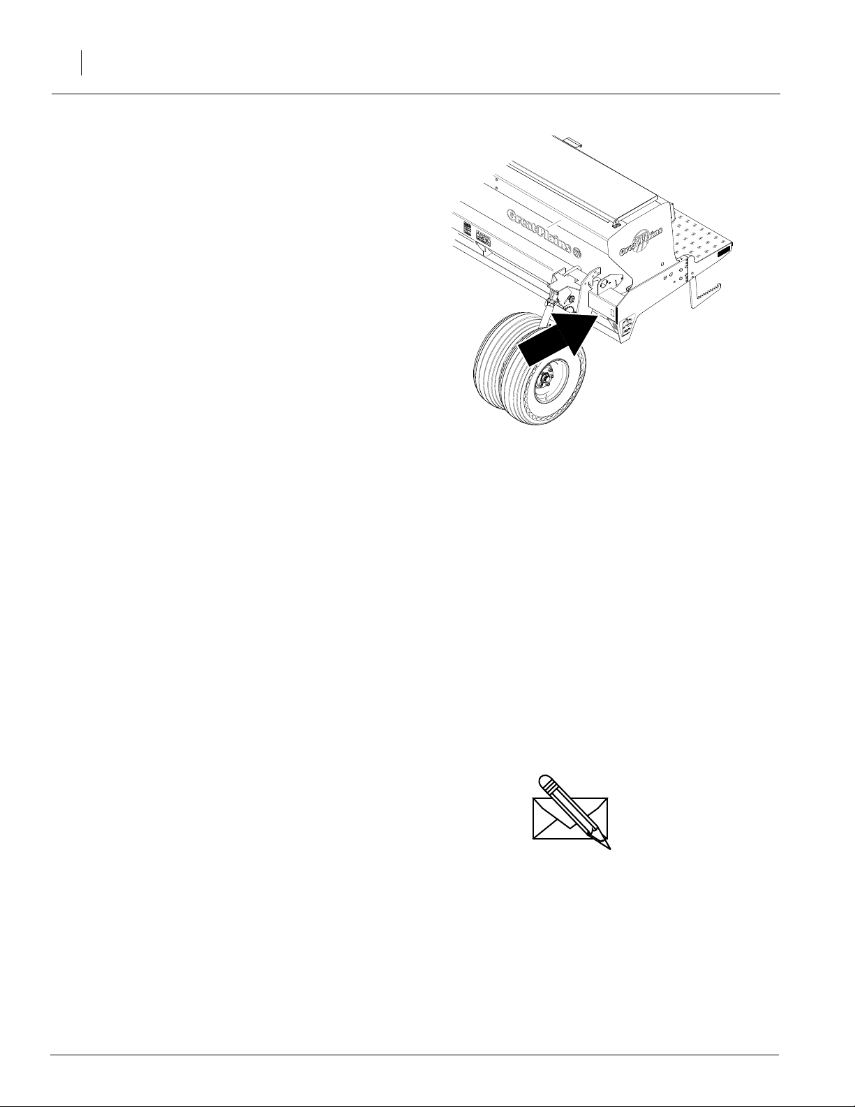
Refer to Figure 2
Your machine’s parts were specially designedand
should only be replaced with Great Plains parts.
Always use the serial and model number when ordering parts from your Great Plains dealer. The
serial-number plate is located on the main frame
tube on the left end of the drill.
Record your drill model and serial number here for
quick reference:
Model Number:__________________________
Serial Number: ___________________________
Figure 2
Serial Number Plate
16490
Your Great Plains dealer wants you to be satisfied
with your new machine. If you do not understand
any part of this manual or are not satisfied with the
service received, please take the following
actions.
1. Discuss the matter with your dealership service manager. Make sure they are aware of
any problems so they can assist you.
2. If you are still unsatisfied, seek out the owner
or general manager of the dealership.
3. For further assistance write to:
Product Support
Great Plains Mfg. Inc., Service Department
PO Box 5060
Salina, KS 67402-5060
8/14/2006
Page 17

Preparation and Setup
This section will help you prepare your tractor and
drill for use. Before using the drill in the field, you
must hitch the drill to a suitable tractor and level
the drill.
Prestart Checklist
1. Read and understand “Important Safety Information,” page 1.
2. Check that all working parts are moving freely, bolts are tight, and cotter pins are spread.
3. Check that all grease fittings are in place and
lubricated. Refer to “Lubrication,” page 52.
4. Check that all safety decals and reflectors are
correctly located and legible. Replace if damaged. See “Safety Decals,” page 7.
Preparation and Setup
15
5. Inflate tires to pressure recommended and
tighten wheel bolts as specified. See “Appendix,” page 56.
Hitching Tractor to Drill
!
DANGER
You may be severely injured or killed by being crushed
between the tractor and drill. Do not stand or place
any part of your body between drill and moving tractor. Stop tractor engine and set park brake before installing the hitch pin.
1. Raise or lower tractor three-point arms as
needed and pin lower arms to drill.
2. Pin upper arm to drill. For category III and IIIN tractors, install hitch pin in the lower hole.
For category IV-N tractors, install hitch pin in
the upper hole.
3. Slowly raise drill. Watch for cab interference.
4. Adjust top three-point link so that top edge of
drill box is parallel with ground when drilling.
NOTE: Do not use link to adjust opener depth. For
opener adjustments, refer to page 25.
5. Set your tractor three-point-draft control to
float position.
6. Plug lead from drill light harness into tractor
receptacle.
8/14/2006
Page 18

1520F, 2020F, 2420F, 1510HDF, &
16
2010HDF
Hydraulic Hose Hookup
Refer to Figure 3
Great Plains hydraulic hoses are color coded to
help you hookup hoses to your tractor outlets.
Hoses that go to the same remote valve are
marked with the same color.
Color Hydraulic Function
Orange Marker Cylinders
To distinguish hoses on the same hydraulic circuit, refer to plastic hose holder. Hose under
extended-cylinder symbol feeds cylinder base
ends. Hose under retracted-cylinder symbol
feeds cylinder rod ends.
17641
Figure 3
Hydraulic Hose Label
8/14/2006
Page 19
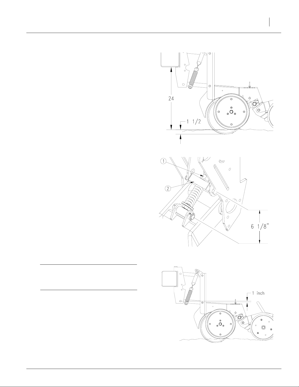
Leveling the Drill
20 Series Opener Single Gauge Wheel
Refer to Figure 4
Initially adjust drill so bottom of opener tube runs
24 inches above ground when drill is lowered in
the field.
Refer to Figure 5
To adjust:
Preparation and Setup
17
1. Make sure block mount of the spring linkage
(2) is in the lower mount hole for planting in
bedded irrigation. The upper hole is for nonbedded ground.
2. Set spring linkage length. Turn spring linkage
to shorten or lengthen as necessary. Initially
set length to 6 1/8 inches between pin centers
to achieve the 24-inch dimension mentioned
above. When adjusting the linkage length, remember:
• Lengthening linkage raises drill.
• Shortening linkage lowers drill.
3. Level drill with top three-point link.
Refer to Figure 6
NOTE: When drill is level, parallel links will be running slightly uphill towards the front.
The 1-inch dimension shown is a general dimension that will vary with planting conditions.
IMPORTANT: Make sure the opener mount is
running higher than the opener body. This will
ensure an ample reserve for opener upfloat in
case the opener strikes a rock or other object.
Figure 4
Initial Operating Height
Figure 5
Spring Linkage
24301
21685
8/14/2006
Figure 6
Leveling the Drill
23402
Page 20
1520F, 2020F, 2420F, 1510HDF, &
18
2010HDF
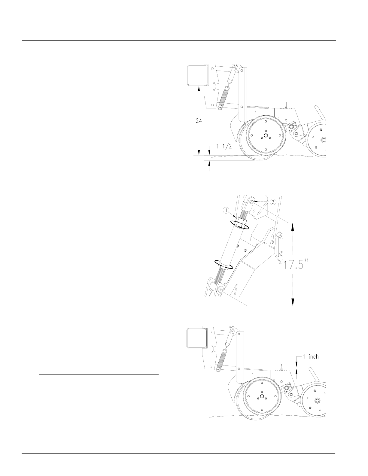
20 Series Opener Dual Gauge Wheels
Refer to Figure 7
Initially adjust drill so bottom of opener tube runs
24 inches above ground when drill is lowered in
the field.
Refer to Figure 8
To adjust:
1. Loosen jam nut near top clevis of each
gauge-wheel turnbuckle.
NOTE: Jam nut is left-hand threaded.
2. Make sure upper clevis (2) is in upper mount
hole as shown.
3. Set turnbuckle length. Turn turnbuckle to
shorten or lengthen as necessary. Initially set
length to 17 1/2 inches between pin centers to
achieve the 24-inch dimension mentioned
above. When adjusting the turnbuckle length,
remember:
Figure 7
Initial Operating Height
24301
• Lengthening turnbuckle raises drill.
• Shortening turnbuckle lowers drill.
4. After adjusting both turnbuckles to the same
length, tighten jam nuts.
5. Level drill with top three-point link.
Refer to Figure 9
NOTE: When drill is level, parallel links will be running slightly uphill towards the front.
The 1-inch dimension shown is a general dimension that will vary with planting conditions.
IMPORTANT: Make sure the opener mount is
running higher than the opener body. This will
ensure an ample reserve for opener upfloat in
case the opener strikes a rock or other object.
Figure 8
Gauge-Wheel Turnbuckle
22845
Figure 9
Leveling the Drill
24302
8/14/2006
Page 21

HD 10 Series Openers with Single Gauge Wheel
Refer to Figure 10
Initially adjust drill so bottom of opener tube runs 26
inches above ground when drill is lowered in the
field.
Refer to Figure 11
To adjust:
1. Make sure block mount of the spring linkage (2)
is in the lower mount hole for planting in bedded
irrigation. The upper hole is for non-bedded
ground.
Preparation and Setup
19
2. Set spring linkage length. Turn spring linkage to
shorten or lengthen as necessary. Initially set
length to 6 1/2 inches between pin centers to
achieve the 26-inch dimension mentioned
above. When adjusting the linkage length, remember:
• Lengthening linkage raises drill.
• Shortening linkage lowers drill.
3. Level drill with top three-point link.
Refer to Figure 12
NOTE: When drill is level, parallel links will be running level or slightly uphill towards the front.
The 1-inch dimension shown is a general dimension that will vary with planting conditions.
IMPORTANT: Make sure the opener mount is
running higher than the opener body. This will
ensure an ample reserve for opener upfloat in
case the opener strikes a rock or other object.
22847
Figure 10
Initial Operating Height
Figure 11
Spring Linkage
24046
8/14/2006
Figure 12
Leveling the Drill
24047
Page 22

1520F, 2020F, 2420F, 1510HDF, &
20
2010HDF
HD 10 Series Openers Dual Gauge Wheels
Refer to Figure 2
Initially adjust drill so bottom of opener tube
runs 26 inches above ground when drill is lowered in the field.
Refer to Figure 3
To adjust:
1. Make sure the top turnbuckle clevis is in
the lower mount hole.
2. Set turnbuckle length. Turn turnbuckle to
shorten or lengthen as necessary. Initially
set length to 17 1/2 inches between pin
centers to achieve the 26-inch dimension
mentioned above. When adjusting the
turnbuckle length, remember:
• Lengthening turnbuckle raises drill.
Figure 2
Initial Operating Height
24050
• Shortening turnbuckle lowers drill.
3. Level drill with top three-point link.
Refer to Figure 4
NOTE: When drill is level, parallel links will be
running slightly uphill towards the front.
The 1 inch dimension shown is a general dimension that will vary with planting conditions.
IMPORTANT: Make sure the opener mount
is running higher than the opener body.
This will ensure an ample reserve for opener upfloat in case the opener strikes a rock
or other object.
Figure 3
Gauge Wheel Turnbuckle
22845
Figure 4
Leveling the Drill
24049
8/14/2006
Page 23

Operating Instructions
This section covers general operating procedures. Experience, machine familiarity and the
following information will lead to efficient operation and good working habits. Always operate
farm machinery with safety in mind.
Prestart Checklist
!
WARNING
Escaping fluid under pressure can have sufficient pressure to penetrate the skin. Check all hydraulic lines
and fittings before applying pressure. Fluid escaping
from a very small hole can be almost invisible. Use paper or cardboard, not body parts, and wear heavy
gloves to check for suspected leaks. If injured, seek
medical assistance from a doctor that is familiar with
this type of injury. Foreign fluids in the tissue must be
surgically removed within a few hours or gangrene
will result.
Operating Instructions
21
1. Carefully read “Important Safety Information,”
page 1.
2. Lubricate drill as indicated under “Lubrication,” page 52.
3. Check all tires for proper inflation. See “Appendix,” page 56.
4. Check all bolts, pins and fasteners. Torque as
shown in “Appendix,” page 56.
5. Check drill for worn or damaged parts. Repair
or replace parts before going to the field.
6. Check hydraulic hoses, fittings and cylinders
for leaks. Repair or replace before going to
the field.
7. Rotate both gauge wheels to see that the
drive and meters are working properly and
free from foreign material.
!
DANGER
Watch your step when walking on drill ladder and
walkboard. Falling from drill could cause severe injury or death.
8/14/2006
Page 24

1520F, 2020F, 2420F, 1510HDF, &
22
2010HDF
Field Operation
!
You may be severely injured or killed by being crushed
between the tractor and drill. Do not stand or place
any part of your body between drill and moving tractor. Stop tractor engine and set park brake before installing pins.
1. Hitch drill to asuitable tractor orhitch. Refer to
2. Set and calibrate seeding rate as explained
3. Check that seed-cup-doorhandles areset the
DANGER
“Hitching Tractor to Drill,” page 15 or your
hitch operator’s manual.
under Seeding Rate, “Adjustments,” page
15.
same across the drill. Refer to Seeding Rate,
“Adjustments,” page 15.
NOTE: If you notice excessive cracking on large
seeds, adjust all seed-cup doors to a wider setting. Use the widest setting only for seed-cup
clean out.
4. Load box with clean seed.
5. Record acremeter readout. Subtract inital
reading from later readings to determine area
drilled.
6. Pull forward, lower drill and begin seeding.
7. Always lift drill out of the ground when turning
at row ends and for other short-radius turns.
Seeding wil stop automatically as drill is
raised in the field.
8/14/2006
Page 25

Opener Operation
IMPORTANT: Do not back up with openers in
the ground. To do so will cause severe damage and opener plugging.
For information on opener adjustments, refer to
page 26 or page 29. For more information on troubleshooting opener problems, see
“Troubleshooting”, page 45.
Marker Operation
Optional marker attachments are available from
your Great Plains dealer. Before operating markers, make sure hydraulics are properly bled as
described under “Marker Adjustments”, page 40.
Dual markers equipped witha sequence valve are
powered off the same hydraulic circuit. Starting
with both markers folded, the folding sequence is:
Operating Instructions
23
1. Activate lever - Right unfolds; left stays
folded.
2. Reverse lever - Right folds; left stays folded.
3. Activate lever - Left unfolds; right stays
folded.
4. Reverse lever - Left folds up; right stays
folded.
5. Sequence repeats.
You can adjust marker folding speed. Refer to
“Marker Adjustments”, page 40, and adjustfolding
speed to a safe rate. Folding markers at high
speed can damage markers.
Transporting
!
WARNING
Towing the drill at high speeds or with a vehicle that is
not heavy enough could lead to loss of vehicle control.
Loss of vehicle control could lead to serious road accidents, injury and death. To reduce the hazard, do not
exceed 20 mph. Check that your tractor has enough
ballast to handle the weight of the drill. Refer to your
tractor operator’s manual for ballast requirements.
NOTE: For transporting with drill attached to a
hitch, refer to your hitch operator’s manual.
Before transporting the drill, follow and check
these items:
8/14/2006
Page 26

1520F, 2020F, 2420F, 1510HDF, &
24
2010HDF
Unload seed box. Unload seed box before trans-
porting if at all possible. To do so:
• Place tarp under drill or a bucket under each
seed meter.
• Use large bucket to empty box as much as
possible. Make sure sliding seed tubes are in
the open position. Open seed meter clean out
to empty seed out of sliding seed tube and
meter.
The drill can be transported with a full box of grain,
but the added weight will increase stopping distance and decrease maneuverability.
NOTE: To maintain steering control, you may
need to add ballast to your tractor front end. Refer
to your tractor operator’s manual for ballast required.
Road rules. Comply with all federal, state and local safety laws when traveling on public roads.
Refer to Figure 17
Clearance. Remember that the drill is wider than
the tractor. Allow safe clearance. Fold up walkboard ladder for maximum clearance.
Transporting with Markers
Always transport markers in the folded position.
Parking
For information on long-term storage, refer to
“Storage”, page 51.
!
WARNING
Empty seed box before unhitching drill to prevent drill
from falling backward.
NOTE: For parking with drill attached to a hitch,
refer to your hitch operator’s manual.
1. Empty seed box.
2. Park drill on a level, solid surface.
3. Lower three-point hitch until drill is on the
ground.
Figure 17
Ladder Folded for Transport
22878
4. Extend or retract the top link of the tractor until
top three-point pin is free. Remove pin.
5. Remove pins from lower links.
8/14/2006
Page 27

Adjustments
Adjustments
25
Side Gauge Wheels for 20 Series
Openers
Refer to Figure 18
The side gauge wheels have two, interrelated adjustments:
• angle of side gauge wheel, and
• distance between side gauge wheel and row unit disk.
Refer to Figure 19
Adjust side-gauge-wheel angle so wheels contact the row
unit disks at bottom of wheel at 2” planting depth.
At the same time, keep side gauge wheels close to the
opener disks so openers do not plug with soil or trash but
far enough out so the disks and wheels turn freely.
• If contact point is between 4 to 8 o’clock but distance to tire is not correct, then add or remove shims
as needed. DO NOT ADJUST BEARING AS THAT
WILL ADJUST WHEEL-TO-DISK CONTACT AREA
ONLY.
Refer to Figure 20
Opener
Disks
Side Gauge
Wheel
Incorrect Correct
Note: Wheel touches at bottom and gaps open 3/8”
to 5/8” at top.
Figure 18
Side Gauge Wheels
8 o’clock
Side Gauge
Wheel
4 o’clock
To adjust Wheel-to-Disk contact area of side gauge
wheels:
1. Raise drill slightly to remove weight from side gauge
wheels.
2. Loosen hex-head bolt (1). Move wheel and arm out on
o-ring bushing.
3. Loosen pivot bolt (2). Turn hex adjuster (3) so indicator
notch (4) is at 5 o’clock to 7 o’clock. Use this as the
starting point for adjustment.
4. Move wheel arm in so side gauge wheel contacts row
unit disk. Tighten hex-head bolt (1) to clamp arm
around bushing and shank.
5. Check wheel-to-disk contact at 2” planting depth. Lift
wheel and arm. When let go, wheel should fall freely.
• If wheel does not contact disk at bottom to area
where blade leaves contact with soil, move hex ad-
juster until wheel is angled for proper contact with disk.
• If wheel does not fall freely, loosen hex-head bolt (1)
and slide wheel arm out just until wheel and arm move
freely. Retighten hex-head bolt (1) according to grade:
• 7/16” Gr 8 bolt on 20 series, 70 ft-lbs.
• 5/8” Gr 8 bolt on 20 series, 150 ft-lbs.
Figure 19
Wheel-to-Disk Contact Area
24006
3
1
2
4
Starting Point
Figure 20
Side Gauge Wheel Adjustment
6. Keep turning hex adjuster and moving wheel arm
until the wheel is adjusted properly. When satisfied, tighten pivot bolt (2) to 110 foot-pounds.
22525
NOTE: Use “Torque Values Chart”, page 56 for reference.
8/14/2006
Page 28

1520F, 2020F, 2420F, 1510HDF, &
26
2010HDF
20 Series Openers
Opener Down Pressure
Refer to Figure 21
Opener springs provide the down pressure necessary for opener disks to open a seed trench.
The springs allow the openers to float down into
depressions and up over obstructions.
You can adjust down pressure individually for
each opener. This is useful for penetrating hard
soil and planting in tire tracks.
Use enough down pressure to cut the seed trench
and maintain proper soil-firming over seed. Excessive opener down force will lead to premature
wear on opener components.
Refer to Figure 22
To adjust down pressure, use adjustment tool
stored under walkboard. Position tool in holes on
spring mounting plates, and pull down. Move the
adjustment cam to the new setting.
Opener Spring
Disk
Figure 21
20 Series Opener with Meter
20451
Refer to Figure 23
Minimum and maximum settings are indicated by
position of adjustment cam.
Press Wheel Adjustment
Press Wheel Adjustment
Minimum setting
Adjustment Cam Settings
Adjustment
Figure 22
Figure 1
Figure 23
Tool
20450
18409
Maximum setting
12104
8/14/2006
Page 29

Adjustments
27
Opener Seeding Depth
Refer to Figure 24
Side depth wheels beside the opener disks control opener seeding depth. The position of an
adjustable stop determines seeding depth.
Refer to Figure 25
Set opener seeding depth by adjusting T-handles.
To adjust, first raise openers slightly, then lift and
slide T-handles on top of openers. Adjust all Thandles to the same setting.
• For shallower seeding, slide T-handles forward toward drill.
• For deeper seeding, slide T-handles back
away from drill.
Disk
Handle
Figure 24
20 Series Opener
20451
Side Depth
Wheel
Press Wheel
Refer to Figure 26
Press wheels are attached to each opener body.
The press wheels close the seed trench and gently press soil over seed.
An adjustable spring in the press-wheel mechanism creates the down pressure needed to close
the seed trench. The amount of force needed will
vary with field conditions.
To adjust, move adjustment handle.
• For less down pressure,move handle forward
toward drill.
• For more down pressure, move handle back
away from drill.
NOTE: Increased press wheel spring force may
require increased opener down force to maintain
depth.
Figure 25
20 Series Opener Depth
Less down
pressure
More down
pressure
Figure 26
Closing Wheel Down Pressure
18285
16629
8/14/2006
Page 30

1520F, 2020F, 2420F, 1510HDF, &
28
2010HDF
NOTE: The factory setting on the press wheel is
staggered to achieve optimum residue flow.
Refer to Figure 27
If you want to adjust press wheels from staggered
to even, remove 5/8 inch bolt (1), lock washer (2)
and nut (3). Reinstall spacer (4), press wheel (5)
and hardware to the other hole location.
Seed-Lok Lock Up
Optional Seed-Lok firming wheels provide additional seed-to-soil contact. The wheels are spring
loaded and do not require adjusting. In some wet
and sticky conditions the wheels may accumulate
soil.
Refer to Figure 28
NOTE: Side gauge wheel and seed meter is removed for clarity.
To lock up Seed-Lok wheels, raise drill. Rotate
lock-up handle (1) 90 degrees down on top of
opener body. Push up on Seed-Lok wheel (2) until
wheel arm latches up.
Hole
locations
Figure 27
Press Wheel Stagger
18410
!
CAUTION
Opener disk blades may be sharp. Use caution when
making adjustments in this area.
To unlock Seed-Lok wheels, pull up lock-up handle (1). Seed-Lok is spring loaded so it will snap
back into place.
18282
Figure 28
Seed-Lok Adjustment
8/14/2006
Page 31

HD 10 Series Openers
Opener Down Pressure
Refer to Figure 38
IMPORTANT: Do not back up with openers in
the ground. To do so will cause severe damage and opener plugging.
Opener springs provide the down pressure necessary for opener disks to open a seed trench.
The springs allow the openers to float down into
depressions and up over obstructions.
You can adjust down pressure individually for
each opener. This is useful for penetrating hard
soil and planting in tire tracks.
Use only enough down pressure to cut the seed
trench and maintain proper soil-firming over seed.
Excessive opener down force will lead to premature wear of opener components. Excessive down
force will also cause uneven seed depth.
Opener spring
Figure 38
Opener Spring
Adjustments
21947
29
Refer to Figure 39
To adjust down pressure, use adjustment wrench
stored under the walkboard or a 1 1/8” open end
wrench. Position wrench on the nutand pulldown.
Move the adjustment cam to the new setting.
Important: Always adjust the Opener Down
Pressure with the drill raised and the openers
in their completely lowered position.
Figure 39
Opener Down Pressure Adjustment
21948
8/14/2006
Page 32

1520F, 2020F, 2420F, 1510HDF, &
30
2010HDF
Refer to Figure 40
Minimum and maximum settings are indicated by
position of adjustment cam.
Each notch on the adjustment cam will increase
the down pressure on the opener springs. Use the
chart below as a setting reference.
Spring Down Pressure
Cam Notch Pounds
one 250
two 275
three 310
four 370
five 430
six 490
Opener Seeding Depth
A press wheel attached to each opener body controls seeding depth. To maintain consistent depth,
the relationship between the bottom of the opener
disks and press wheel is fixed upwardly.
The press wheels also close the seed trench and
gently press soil over seed. To provide consistent
soil firming, press wheels are free to move down
from normal operating position. This maintains
pressing action even if opener disks encounter
obstructions or hard soil.
Minimum setting
Maximum setting
Figure 40
Adjustment Cam Settings
21966
21967
Refer to Figure 41
Set opener seeding depth by adjusting T-handles.
To adjust, first raise openers slightly, then lift and
slide T-handles on top of openers as shown. Adjust all T-handles to the same setting.
• For shallower seeding, slide T-handles forward toward drill.
• For deeper seeding, slide T-handles back
away from drill.
Figure 41
Seed Depth Adjustment
12100
8/14/2006
Page 33

Double V Press Wheel Adjustment
Refer to Figure 42
The double V closing wheels (4) can be moved inward and outward to alter how they close the seed
trench and press soil over the seed.
To move the wheels (4) in toward the center of the
trench, remove one of the 1/4 bushings (2) next to
the press wheel arm and position it under the
head of the bolt (1). On wider row spacings the
closing wheels (4) can be moved outward by placing two 1/4 spacers (2) inside next to the press
wheel arm (3).
Adjustments
31
8/14/2006
23428
Figure 42
Double V Press Wheel
Page 34

1520F, 2020F, 2420F, 1510HDF, &
32
2010HDF
Lock-Up
The openers can be pinned in the up position to
accommodate 30” row spacing.
Refer to Figure 43
1. Select the individual opener you want to keep
in the raised position. It is suggested that the
down pressure springs be set to the minimum
setting first.
Lower parallel
arm
2. Raise the opener high enough that the hole
for the pin is above the lower parallel arm.
This can easily be done by placing a small
block below the disc blades and setting the
drill down upon it.
3. Insert locking pin through both holes and lower the opener allowing the pin to rest on the
top of the lower parallel arm.
NOTE: Do not pin the opener while it is in the lowered position. If the pin is inserted below the parallel arm it WILL damage opener soon after
planting begins.
Refer to Figure 44
When pin is not being used for opener lock-up always return pin to the storage position.
21981
22517
Pin in place
Figure 43
Hole for Lock-Up Pin
Pin in storage
position
Figure 44
Hole for Lock-Up Pin Storage
8/14/2006
Page 35

Frame Height
Drill operating height directly affects the working
range of the drill openers. Initially adjust frame
height as explained under “Leveling Drill”, page 17.
You can make further adjustments to compensate
for field conditions.
Single Gauge Wheel
Refer to Figure 45
1. Make sure block mount of the spring linkage (2)
is in the lower mount hole for planting in bedded
irrigation. The upper hole is for non-bedded
ground.
2. Set spring linkage length. Turn spring linkage to
shorten or lengthen as necessary. Initially set
length to 6 1/2 inches between pin centers to
achieve a 26-inch frame height for HD 10 series
openers and 6 1/8 inches to achieve a 24-inch
frame height for 20 series openers. When adjusting the linkage length, remember:
Adjustments
33
• Lengthening linkage raises drill.
• Shortening linkage lowers drill.
Level drill with top three-point link.
NOTE: Lowering the drill increases the risk of opener damage on rocks or obstructions.
Dual Gauge Wheels
Refer to Figure 46
1. Loosen jam nut near top clevis of each gaugewheel turnbuckle.
NOTE: Jam nut is left-hand threaded.
2. Make sure upper clevis (2) is in upper mount
hole as shown for 20 series and in the lower
mount hole for HD 10 series.
3. Set turnbuckle length. Turn turnbuckle to shorten or lengthen as necessary. Initially set length
to 17 1/2 inches between pin centers to achieve
a 24-inch dimension for 20 series openers and
26-inch dimension for HD 10 series openers.
When adjusting the turnbuckle length, remember:
Figure 45
Single Gauge Wheel Linkage
22848
• Lengthening turnbuckle raises drill.
• Shortening turnbuckle lowers drill.
4. After adjusting both turnbuckles to the same
length, tighten jam nuts.
5. Level drill with top three-point link.
NOTE: Lowering the drill increases the risk of opener damage on rocks or obstructions.
8/14/2006
Figure 46
Dual Gauge Wheel Turnbuckle
22845
Page 36

1520F, 2020F, 2420F, 1510HDF, &
34
2010HDF
Seeding Rate
Adjusting the seeding rate requires the following:
1. adjusting drive sprockets,
2. setting seed-rate handle,
3. positioning seed-cup doors,
4. checking seeding rate.
Refer to the seed rate charts on page 37. These
charts list proper sprocket sizes and seed rate
handle settings for various seeds and seeding
rates.
The seed rate charts are based on cleaned, untreated seed of average size and test weight. The
charts are based on 9.5L x 15 rib implement tires
for 15ft drills and 11L x 15 rib implement tires for
20ft and 24ft drills.
Many factors will affect seeding rates including
foreign material, seed treatment, seed size, seed
weight, field conditions, and tire pressure. You
likely will need to make minor adjustments. Set
and check the seeding rate, then readjust the rate
as necessary.
Before setting the seeding rate, rotate the gauge
wheels. Check that seed cups and drive are working properly and free from foreign material.
Adjust Drive Sprockets
Install drive sprockets for the drive type for your
desired seeding rate.
For correct drive type, refer to seed rate charts beginning on page 18. The charts list drive types as
1, 2, 3, or 4. Refer to the following table for the correct-sized sprocket for each drive type.
Reroute drive chain over sprockets and idlers as
shown in Figure 5. Move idlers into chain so
chain has 1/4-inch slack in its longest span.
Tighten idlers.
17669
Figure 5
Driver and Driven Sprockets
Set same drive type on both drill sections.
Set Seed Rate Handle
Position seed rate handle for each drill box as indicated on seed rate chart. One handle is shown
in Figure 6.
To adjust seed rate handle, loosen wing nut under handle. Slide handle until indicator isjust past
the correct setting. Retighten wing nut.
Drive Type Driver Driven Speed
Type 1 14 Tooth 44 Tooth Slowest
Type 2 24 Tooth 36 Tooth Two Times Faster
Than Type 1
Type 3 24 Tooth 24 Tooth Three Times Faster
Than Type 1
Type 4 24 Tooth 15 Tooth Five Times Faster
Than Type 1
To change drive sprockets, refer to Figure 5. Loosen idler plate (1) and remove drive chain (2) .
Remove lynch pins from shafts and rearrange
driver (3) and driven (4) sprockets.
17618
Figure 6
Seed Rate Handle
8/14/2006
Page 37

Adjustments
35
Position Seed Cup Doors
For wheat and other smal seeds, move seed cup
door handles to highest position. For soybeans
and other large seeds, lower handles to second
position. If excessive seed cracking occurs, lower
handles to third position. For seed cup clean out,
move handles to fourth, wide-open position. Make
sure all handles are in same position before
drilling.
NOTE: If your results vary greatly from the charts,
you may want to repeat the calibration procedure.
8. When drilling, note acres drilled, amount of
seed added and level of seed in drill box. If
you are seeding more or less than desired,
adjust seeding rate slightly to compensate for
your field conditions.
Check Seeding Rate
1. Record the weight of an empty container
large enough to hold seed metered for one
acre.
2. Place several pounds of seed over three
seed cups on an outside end of drill box. Pull
seed tubes off these three openers.
3. Raise drill off ground.
4. Turn gauge wheel a few turns to fill cups with
seed. Turn wheel until seed drops to ground
from all three cups.
5. Place a container under the three seed tubes
to gather seed as it is metered.
6. Turn drive gauge wheel for one acre. Refer to
the chart on the next page for the exact number of tire revolutions to equal one acre.
Check that three seed cups have plenty of
seed coming into them.
7. Weigh metered seed. Subtract initial weight
of empty container. Divide by three for the
amount metered by each seed cup, then multiply by the number of drill openers for the
pounds per acre seeding rate. If this figure is
different than desired, adjust the seed rate
handle and recheck the rate.
8/14/2006
Page 38

1520F, 2020F, 2420F, 1510HDF, &
36
2010HDF
Tire Revolutions Per Acre
Planted Row
Spacing (Inches)
7 1/2” 24 365 32 268 38 225
9 1/2” 26 260
10” 18 365 24 268 28 229
10” 19 346 25 257
15” 12 365 16 268 19 225
15” 13 337 17 252 20 214
19” 13 260
20” 9 365 12 268 14 229
20” 10 329
30” 6 365 8 268 10 214
36” 6 297
38” 6 282
40” 6 268
Twin Row 30” beds 12 365 16 268 20 214
Number of
Rows for 15ft
drills
Tire
Revolutions
per Acre for
15ft drills
Number of
Rows for 20ft
drills
Tire
Revolutions
per Acre for
20ft drills
Number of
Rows for
24ft drills
Tire
Revolutions
per Acre for
24ft drills
Twin Row 36” beds 12 297 16 223
Twin Row 38” beds 12 282 16 211
Twin Row 40” beds 12 268 16 201
Twin Row 30” W/S 19 346 25 257 29 221
15” Skip Row 14 268
NOTE: Blank spaces denote row spacings that are not available for specific drill models.
8/14/2006
Page 39

Adjustments
Seed Rate Chart (pounds per acre)
Setting number 0 5 10 15 20 25 30 35 40 45 50 55 60 65 70 75 80 85 90 95 100
Alfalfa or
Rape
Drive Type 1
(Based on
60#/bu)
Barley
Drive Type 1
(Based on
51#/bu)
Barley
Drive Type 2
(Based on
51#/bu)
6" 2 6 8 12 15 19 23 27 32 37 41 45 50 54 59 63 69 74 79 82 84
7" 2 5 7 10 13 16 20 23 27 32 35 38 43 47 51 54 59 63 68 70 72
7.5" 2 4 7 10 12 15 18 22 25 29 33 36 40 43 47 51 55 59 63 65 67
8" 2 4 6 9 12 14 17 20 24 28 31 34 37 41 44 47 52 55 60 61 63
Row Spacing
10"
1 3 5 7 9 12 14 16 19 22 25 27 30 33 35 38 41 44 48 49 50
6" 2 5 8 11 14 18 22 26 30 35 39 43 48 53 57 62 66 69 73 73 74
7" 2 4 7 9 12 16 19 22 26 30 33 37 41 45 49 53 56 59 62 63 63
2 4 6 9 12 15 18 21 24 28 31 35 38 42 46 49 52 55 58 59 59
7.5"
8" 1 3 6 8 11 14 17 20 23 26 29 32 36 40 43 46 49 52 54 55 55
Row Spacing
10"
1 3 5 6 9 11 13 16 18 21 23 26 29 32 34 37 39 42 44 44 44
6" 4 9 16 22 30 37 45 54 62 71 76 87 96 104 114 123 133 142 152 154 156
7" 3 7 14 19 26 32 39 46 53 61 68 75 82 89 97 105 114 122 130 132 134
7.5" 3 7 13 17 24 30 36 43 49 57 64 70 77 83 91 98 106 114 121 123 125
8" 3 7 12 16 22 28 34 40 46 53 60 65 72 78 85 92 100 107 114 116 117
Row Spacing
10" 2 5 10 13 18 22 27 32 37 43 48 52 58 63 68 74 80 85 91 92 94
37
Barley
Drive Type 4
(Based on
51#/bu)
Buck
Wheat
Drive Type 3
(Based on
48#/bu)
Flax or
Sudan
Drive Type 1
(Based on
55#/bu)
Millet
Drive Type 1
(Based on
60#/bu)
Milo
Drive Type 1
(Based on
64#/bu)
6" 9 21 39 53 73 90 110 131 151 174 194 213 234 255 278 300 325 348 371 377 382
7" 7 18 33 45 63 78 95 113 130 149 166 182 201 218 238 257 278 299 318 323 328
7.5" 7 17 31 42 58 72 88 105 121 139 155 170 188 204 222 240 260 279 297 301 306
8" 6 16 29 40 55 68 83 99 113 130 146 160 176 191 208 225 244 261 278 282 287
Row Spacing
10" 5 13 23 32 44 54 66 79 91 104 117 128 141 153 167 180 195 209 222 226 230
6" 0 11 21 29 42 52 65 78 92 107 123 136 150 165 180 195 209 224 240 242 245
7" 0 10 18 25 36 45 56 67 79 92 106 116 129 142 154 168 179 192 205 207 210
7.5" 0 9 17 24 34 42 52 62 74 85 99 109 120 132 144 156 167 179 192 194 196
8" 0 8 16 22 31 39 49 59 69 80 92 102 113 124 135 147 157 168 180 181 183
Row Spacing
10" 0 7 13 18 25 31 39 47 55 64 74 81 90 99 108 117 126 134 144 145 147
6" 0 4 8 12 16 20 24 28 33 37 42 46 50 54 59 65 70 76 82 83 85
7” 0 3 7 10 14 17 21 24 28 32 36 39 43 47 51 55 60 65 70 71 73
7.5" 0 3 7 9 13 16 19 23 26 30 34 37 40 44 47 52 56 61 66 67 68
8" 0 3 6 9 12 15 18 21 25 28 31 34 37 41 44 49 52 57 61 62 64
Row Spacing
10” 0 2 5 7 10 12 15 17 20 22 25 27 30 33 35 39 42 45 49 50 51
6" 1 5 8 12 16 20 23 27 32 36 40 44 49 52 57 62 66 71 76 77 78
7" 1 4 7 10 13 17 20 23 27 31 34 38 42 45 49 53 57 61 65 66 67
7.5" 1 4 7 9 13 16 19 22 25 29 32 35 39 42 46 49 53 57 61 62 63
8" 1 4 6 9 12 15 18 20 24 27 30 33 36 39 43 46 50 53 57 58 59
Row Spacing
10" 1 3 5 7 9 12 14 16 19 21 24 26 29 32 34 37 40 43 46 46 47
6" 0 5 9 13 18 23 28 34 39 45 52 57 63 69 75 81 87 92 98 100 102
7" 0 4 8 11 15 19 24 29 34 38 44 49 54 59 64 69 74 79 84 86 88
7.5” 0 4 7 10 14 18 22 27 31 36 41 45 50 55 60 65 69 73 78 80 82
8" 0 4 7 10 13 17 21 25 29 34 39 43 47 52 56 61 65 69 73 75 77
Row Spacing
10" 0 3 5 8 11 14 17 20 23 27 31 34 38 41 45 49 52 55 59 60 61
Oats
Drive Type 3
(Based on
37#/bu)
8/14/2006
6" 0 5 12 17 24 32 39 47 55 63 72 80 88 96 105 113 121 130 139 140 140
7" 0 5 10 15 21 27 33 40 47 54 62 68 76 82 90 97 104 111 119 120 120
7.5" 0 4 10 14 19 25 31 37 44 51 58 64 70 77 84 90 97 104 111 112 112
8" 0 4 9 13 18 24 29 35 41 47 54 60 66 72 78 85 91 97 104 105 105
Row Spacing
10" 0 3 7 10 14 19 23 28 33 38 43 48 53 58 63 68 73 78 83 84 84
Page 40

1520F, 2020F, 2420F, 1510HDF, &
38
2010HDF
Setting number 0 5 10 15 20 25 30 35 40 45 50 55 60 65 70 75 80 85 90 95 100
6" 0 0 19 34 52 69 84 102 119 137 154 169 186 202 218 235 251 266 281 283 284
Peas
Drive Type 3
(Based on
61#/bu)
Pinto
Beans
Drive Type 1
(Based on
61#/bu)
Rice
Short Grain
Drive Type 3
(Based on
43#/bu)
Rice
Short Grain
Drive Type 4
(Based on
43#/bu)
7" 0 0 16 29 45 59 72 87 102 118 132 145 160 173 187 202 215 228 241 243 244
7.5”
0 0 15 27 42 55 67 82 95 110 123 136 149 161 175 188 201 213 225 226 227
8" 0 0 14 26 39 52 63 76 89 103 116 127 140 151 164 177 188 200 211 212 213
Row Spacing
0 0 11 20 31 41 50 61 71 82 93 102 112 121 131 141 151 160 169 170 171
10"
6" 0 0 9 13 17 24 30 35 41 47 53 58 64 69 74 81 85 91 97 96 96
7" 0 0 7 11 15 20 25 30 35 40 45 50 55 59 64 69 73 78 83 83 83
7.5"
0 0 7 10 14 19 24 28 33 38 42 47 51 55 60 65 68 73 77 77 77
8" 0 0 6 10 13 18 22 27 31 35 40 44 48 52 56 61 64 68 72 72 72
Row Spacing
0 0 5 8 10 14 18 21 25 28 32 35 38 41 45 49 51 54 58 58 58
10"
6" 3 11 18 28 38 46 56 64 73 84 96 107 117 128 139 148 167 165 174 174 174
7" 3 9 16 24 33 39 48 54 63 72 82 92 101 110 119 127 134 142 149 149 149
7.5" 2 9 14 23 31 37 44 51 59 67 77 85 94 102 111 118 125 132 139 139 139
8" 2 8 14 21 29 34 42 48 55 63 72 80 88 96 104 111 117 124 131 131 131
Row Spacing
10" 2 7 11 17 23 27 33 38 44 50 57 64 70 77 83 89 94 99 105 105 105
6" 5 18 29 46 63 74 91 104 120 137 156 174 191 209 226 241 255 269 284 284 284
7" 4 15 25 40 54 64 78 89 103 117 134 149 164 179 194 207 219 231 243 243 243
7.5" 4 14 24 37 50 60 72 83 96 109 125 139 153 167 181 193 204 215 227 227 227
8" 4 13 22 35 47 56 68 78 90 102 117 131 143 156 169 181 191 202 213 213 213
Row Spacing
10" 3 11 18 28 38 45 54 62 72 82 94 105 115 125 136 145 153 162 170 170 170
Rice
Long Grain
Drive Type 1
(Based on
47#/bu)
Rice
Long Grain
Drive Type 2
(Based on
47#/bu)
Rice
Long Grain
Drive Type 3
(Based on
47#/bu)
Rice
Long Grain
Drive Type 4
(Based on
47#/bu)
Rye
Drive Type 1
(Based on
57#/bu)
6" 0.0 1.4 4.4 7.4 10.4 13.7 16.8 19.8 22.9 26.1 31.6 32.1 35.1 38.1 41.1 44.3 46.8 49.4 51.5 52.9 53.9
7" 0.0 1.2 3.8 6.3 8.9 11.7 14.4 17.0 19.7 22.4 27.1 27.5 30.1 32.7 35.2 38.0 40.1 42.4 44.2 45.3 46.2
7.5" 0.0 1.1 3.6 5.9 8.3 10.9 13.5 15.9 18.4 20.9 25.3 25.7 28.1 30.5 32.9 35.4 37.5 39.5 41.2 42.3 43.1
8" 0.0 1.1 3.3 5.5 7.8 10.2 12.6 14.9 17.2 19.6 23.7 24.1 26.3 28.6 30.8 33.2 35.1 37.1 38.6 39.7 40.4
Row Spacing
10" 0.0 0.8 2.7 4.4 6.2 8.2 10.1 11.9 13.8 15.7 19.0 19.3 21.1 22.9 24.7 26.6 28.1 29.7 30.9 31.7 32.3
6" 0 3 9 15 21 28 35 41 47 54 65 66 72 78 85 91 96 102 106 109 111
7" 0 3 8 13 18 24 30 35 40 46 56 57 62 67 72 78 83 87 91 93 95
7.5" 0 2 7 12 17 23 28 33 38 43 52 53 58 63 68 73 77 81 85 87 89
8" 0 2 7 11 16 21 26 31 35 40 49 50 54 59 63 68 72 76 80 82 83
Row Spacing
10" 0 2 6 9 13 17 21 25 28 32 39 40 43 47 51 55 58 61 64 65 67
6" 0 0 13 22 32 42 53 61 71 81 90 98 107 116 125 135 144 153 161 167 173
7” 0 0 11 19 27 36 45 53 61 69 77 84 91 99 107 116 124 131 138 143 148
7.5" 0 0 11 17 25 34 42 49 57 65 72 79 85 92 100 108 116 123 129 134 138
8" 0 0 10 16 24 31 40 46 53 61 67 74 80 87 94 101 108 115 121 125 130
Row Spacing
10" 0 0 8 13 19 25 32 37 42 49 54 59 64 69 75 81 87 92 97 100 104
6" 0 0 22 35 52 68 86 100 115 132 146 160 174 188 204 220 235 250 263 273 282
7" 0 0 18 30 44 59 74 86 99 113 125 137 149 161 175 188 202 214 225 234 242
7.5" 0 0 17 28 41 55 69 80 92 105 117 128 139 151 163 176 188 200 210 218 226
8" 0 0 16 27 39 51 65 75 87 99 110 120 130 141 153 165 177 187 197 204 211
Row Spacing
10” 0 0 13 21 31 41 52 60 69 79 88 96 104 113 123 132 141 150 158 164 169
6" 0 3 8 13 19 24 28 35 41 47 53 58 63 68 74 81 87 94 101 102 102
7" 0 2 7 11 16 21 24 30 35 40 45 50 54 59 63 69 74 80 87 87 88
7.5" 0 2 6 10 15 19 22 28 33 38 42 46 50 55 59 64 69 75 81 81 82
8" 0 2 6 10 14 18 21 26 31 35 40 44 47 51 55 60 65 70 76 76 77
Row Spacing
10" 0 2 5 8 11 14 17 21 24 28 32 35 38 41 44 48 52 56 61 61 61
8/14/2006
Page 41

Adjustments
Setting number 0 5 10 15 20 25 30 35 40 45 50 55 60 65 70 75 80 85 90 95 100
6" 0 3 8 13 19 23 29 34 39 45 49 55 61 66 71 77 82 87 93 93 93
Soybeans
Drive Type 1
(Based on
58#/bu)
Soybeans
Drive Type 2
(Based on
58#/bu)
Soybeans
Drive Type 3
(Based on
58#/bu)
Soybeans
Drive Type 4
(Based on
58#/bu)
7" 0 2 7 11 17 20 25 29 34 38 42 48 52 57 61 67 70 75 79 80 80
0 2 6 11 15 19 23 27 31 36 40 44 49 53 57 62 65 70 74 74 75
7.5"
8" 0 2 6 10 15 17 22 25 29 34 37 42 46 50 54 58 61 65 69 70 70
Row Spacing
10" 0 2 5 8 12 14 17 20 24 27 30 33 37 40 43 46 49 52 56 56 56
6" 0 6 16 27 40 48 59 69 80 92 102 114 125 136 147 158 167 179 190 191 192
7" 0 5 14 23 34 41 51 59 69 79 87 98 107 117 126 136 144 153 163 164 164
7.5” 0 5 13 22 32 38 47 55 64 73 81 91 100 109 118 127 134 143 152 153 153
8" 0 4 12 20 30 36 44 52 60 69 76 86 94 102 110 119 126 134 143 143 144
Row Spacing
10" 0 4 10 16 24 29 35 42 48 55 61 68 75 82 88 95 101 107 115 115 115
6" 0 12 23 40 60 71 89 101 116 131 148 164 181 196 214 228 248 265 284 284 284
7" 0 10 19 35 51 61 76 87 100 113 127 141 155 168 183 195 213 227 244 243 244
7.5" 0 9 18 32 48 57 71 81 93 105 119 131 145 157 171 182 199 212 227 227 227
8" 0 9 17 30 45 53 67 76 87 99 111 123 136 147 160 171 186 199 213 213 213
Row Spacing
10" 0 7 14 24 36 42 53 61 70 79 89 98 108 118 128 137 149 159 170 170 170
6" 0 19 37 66 97 115 145 165 190 214 241 267 295 320 348 371 405 433 463 463 464
7" 0 16 31 56 83 99 124 141 163 184 207 229 253 274 299 318 347 371 397 397 397
7.5" 0 15 29 53 78 92 116 132 152 171 193 214 236 256 279 297 324 346 370 371 371
8" 0 14 28 49 73 86 109 124 142 161 181 200 221 240 261 278 304 324 347 347 348
Row Spacing
10" 0 11 22 40 58 69 87 99 114 128 145 160 177 192 209 223 243 260 278 278 278
39
Sun
flowers
Drive Type 1
(Based on
28#/bu)
Wheat
Drive Type 2
(Based on
64#/bu)
Wheat
Drive Type 3
(Based on
64#/bu)
Wheat
Grass
Drive Type 1
(Based on
23#/bu)
6" 0 0 2 4 6 8 11 13 15 18 20 23 25 27 30 32 34 36 38 39 41
7" 0 0 2 4 5 7 9 11 13 15 17 19 21 23 25 27 29 31 33 34 35
7.5" 0 0 2 3 5 7 9 10 12 14 16 18 20 22 24 26 27 29 31 32 33
8" 0 0 2 3 5 6 8 10 12 13 15 17 19 21 22 24 26 27 29 30 31
Row Spacing
10" 0 0 1 3 4 5 6 8 9 11 12 14 15 16 18 19 20 22 23 24 24
6" 0 13 22 30 40 50 57 70 80 91 105 115 127 140 152 164 177 190 203 205 206
7" 0 11 19 26 34 43 49 60 69 78 90 99 109 120 131 141 152 163 174 176 177
7.5" 0 10 18 24 32 40 46 56 64 73 84 92 102 112 122 131 142 152 162 164 165
8" 0 9 17 23 30 37 43 52 60 69 79 86 96 105 114 123 133 143 152 153 154
Row Spacing
10" 0 8 13 18 24 30 34 42 48 55 63 69 76 84 91 99 106 114 122 123 124
6" 0 16 31 45 60 74 88 104 120 137 153 168 186 202 220 240 256 274 290 297 299
7" 0 14 26 38 51 64 75 89 103 117 131 144 159 174 189 206 219 235 248 254 256
7.5" 0 13 25 36 48 59 70 83 96 109 123 134 149 162 176 192 205 219 232 237 239
8" 0 12 23 34 45 56 66 78 90 102 115 126 139 152 165 180 192 205 217 223 224
Row Spacing
10" 0 10 18 27 36 45 53 62 72 82 92 101 111 121 132 144 154 164 174 178 179
6" 0 1 2 3 4 5 6 7 8 10 11 12 13 14 15 17 18 19 19 21 21
7" 0 1 2 3 4 4 5 6 7 8 9 10 11 12 13 14 15 17 16 18 18
7.5" 0 1 2 2 3 4 5 6 7 8 9 10 11 11 12 13 14 15 15 17 17
8" 0 1 2 2 3 4 5 6 6 7 8 9 10 11 12 13 13 15 14 16 16
Row Spacing
10" 0 1 1 2 3 3 4 4 5 6 7 7 8 9 9 10 11 12 11 13 13
8/14/2006
Page 42

1520F, 2020F, 2420F, 1510HDF, &
40
2010HDF
Marker Adjustments
Bleeding Marker Hydraulics
To fold properly, the marker hydraulics must be
free of air. If the markers fold in jerky, uneven motions, follow these steps.
!
CAUTION
You may be injured if hit by a folding or unfolding
marker. Markers may fall quickly and unexpectedly if
the hydraulics fail. Never allow anyone near the drill
when folding or unfolding the markers.
!
WARNING
Escaping fluid under pressure can have sufficient pressure to penetrate the skin. Check all hydraulic lines
and fittings before applying pressure. Fluid escaping
from a very small hole can be almost invisible. Use paper or cardboard, not body parts, and wear heavy
gloves to check for suspected leaks. If injured, seek
medical assistance from a doctor that is familiar with
this type of injury. Foreign fluids in the tissue must be
surgically removed within a few hours or gangrene
will result.
Check that tractor hydraulic reservoir is full.
1. With both markers lowered into field position,
loosen hydraulic-hose fittings at rod and base
ends of marker cylinders. If applicable, loosen
fittings on back side of sequence valve.
IMPORTANT: Never bleed an O-ring fitting. Instead, bleed a nearby pipe or JIC fitting.
2. With tractor idling, activate tractor hydraulic
valve until oil seeps out around a loosened fitting. Tighten that fitting.
IMPORTANT: JIC fittings do not require high
torque. JIC and O-ring fittings do not require
sealant. Always use liquid pipe sealant when
adding or replacing pipe-thread fittings. To
avoid cracking hydraulic fittings from over
tightening, do not use plastic sealant tape.
3. Reactivate tractor hydraulic valve until oil
seeps out around another loosened fitting.
Tighten that fitting. Repeat process until all
loosened fittings have been bled and tightened.
8/14/2006
Page 43

Folding Speed with Needle Valves
Refer to Figure 78
A needle valve controls the folding speed of markers that areplumbed separately. The needle valve
is near the rod end of the marker cylinder.
With tractor idling at a normal operating speed,
adjust marker folding to a safe speed. Turn adjustment knob clockwise to reduce folding speed or
counterclockwise to increase folding speed. Excessive folding speed could damage markers and
void the warranty.
Adjustments
41
Folding Speed with Sequence Valve
Refer to Figure 79
If markers are tied together with an optional sequence valve (P/N 113-466A), adjust folding
speed with hex adjustment screws on the sequence-valve body. There is one adjustment
screw for raising speed (1) and one for lowering
speed (2). Identify adjustment screws by markings stamped in valve body.
With tractor idling at a normal operating speed,
adjust marker folding to a safe speed. Turn adjustment screws clockwise to decrease folding speed
and counterclockwise to increase folding speed.
Excessive folding speed could damage markers
and void the warranty.
After adjusting the folding speed, tighten jam nuts
on hex adjustment screws to hold settings.
Marker Disk Adjustment
Figure 78
Needle Valve
Hex adjustment
screws
Figure 79
Speed Adjustment, Sequence Valve
Increase
speed
Decrease
speed
17620
14048
!
CAUTION
Marker disks may be sharp. Use caution when making
adjustments in this area.
Changing disk angle
Refer to Figure 80
If mark left by marker disk is not clearly visible, adjust disk angle to make a wider mark. Loosen two
1/2 inch bolts (1) holding disk assembly (2). Rotate disk assembly as desired.
8/14/2006
Figure 80
Disk Angle
11757
Page 44

1520F, 2020F, 2420F, 1510HDF, &
42
2010HDF
Marker Chain
There are two, interrelated adjustments for the
marker chain. Make these adjustments in the following order.
Refer to Figure 81
1. Lifting Slack. With marker unfolded, back fullthreaded adjustment bolt (1) down until head
extends as little as possible. Slowly fold marker
while observing disk. If marker disk slides
across ground more than a foot before chain
and linkage lifts it up, the chain is too long.
Shorten chain one or two links by moving clevis
(2). Check adjustment by repeating folding process.
If chain is too short when marker is unfolded, it
will prevent end of marker from dropping into
field depressions, causing skips in your marker
line. Correct this condition by lengthening chain
one or two links at clevis (2).
2. Folding Slack. Fold marker. Use full-threaded
adjustment bolt (1) to take slack out of chain
while marker is folded. Extend bolt until there is
no chain slack. Lock bolt in this position by tightening nuts (3) on either side of upright channel
(4).
Shear Bolt
15669
Figure 81
Marker Chain Adjustment
Transport Carrier
When marker is folded, the second section should
rest in transport-carrier saddle.
Refer to Figure 82
To adjust front-to-rear position of saddle, loosen the
5/8 X 7-inch u-bolts (1) that fasten transport-carrier
mount onto box frame. Slide transport-carrier assembly forward or back as needed.
To adjust height of saddle, loosen 1/2-by-2-inch ubolts (2) that hold carrier tube to mounting bracket.
Slide carrier tube up or down as needed.
15632
Figure 82
Adjusting Marker Carrier
8/14/2006
Page 45

Marker Width
Refer to Figure 83
To adjust marker width, loosen jam nuts (1) and
1/2-inch set screws (2). Move marker disk tube in
or out to get the proper dimension.
Adjustments
Figure 83
Marker Width Adjustment
43
19204
8/14/2006
Page 46

1520F, 2020F, 2420F, 1510HDF, &
44
2010HDF
Seed-Lok™ Lock Up
Optional Seed-Lok™ firming wheels provide additional seed-to-soil contact. The wheels are
spring loaded and do not require adjusting. In
some wet and sticky conditions the wheels may
accumulate soil.
Refer to Figure 85
NOTE: Side gauge wheel and seed meter is removed for clarity.
To lock up Seed-Lok™ wheels, raise drill. Rotate
lock-up handle (1) 90 degrees down on top of
opener body, see insert. Push up on Seed-Lok™
wheel (2) until wheel arm latches up.
!
CAUTION
Opener disk blades may be sharp. Use caution when
making adjustments in this area.
To unlock Seed-Lok™ wheels, pull up lock-up
handle (1). Seed-lok™ is spring loaded so it will
snap back into place.
Locked
position.
Unlocked
position.
Push Seed-Lok™
up to lock.
18282
Figure 85
Seed-Lok™ Lock Up
8/14/2006
Page 47

Troubleshooting
Problem Solution
Troubleshooting
45
Uneven seed spacing or uneven stand
Opener disks not turning freely
Check for plugging in seed cups.
Check for plugging in seed tubes.
Reduce ground speed.
Check if opener disks are turning freely.
Use faster drive type and position seed rate handle to a lower setting.
Increase opener spring pressure to penetrate low spots. Refer to
Opener Down Pressure, “Adjustments,” page 25.
Check for trash or mud build-up on Seed-Lok wheels.
Check for trash or mud build-up on disk scraper. Adjust scraper.
Refer to HD 10 Series Disk Spreaders and Scrapers, “Maintenance,”
page 50.
Check if scraper is adjusted too tight, restricting disk movement.
Refer to HD 10 Series Disk Spreaders and Scrapers, “Maintenance,”
page 50.
Check disk bearings.
Check opener frame for damage.
If opener disks turn freely by hand but not in field, reduce down pressure on disk opener. Refer to Opener Down Pressure, “Adjustments,”
page 25.
Check press wheel adjustment. On HD10 Series Openers, refer to
Opener Seeding Depth, “Adjustments,” page 30. On 20 Series Openers, refer to Opener Down Pressure, “Adjustments,” page 26.
Actual metering rate is different than
desired
Acremeter does not measure accurately
Press wheels not compacting the soil as
desired
Check tire pressure. Proper inflation is listed on the Tire Inflation
Chart, “Appendix,” page 57.
Check tire size. Proper size is 9.5L x 15 for 15 foot drills and 11L x 15
for 20 foot drils and 24 foot drills.
Regularly clean seed treatment from seed cups.
Check drill box setting.
Refer to Seeding Rate, “Adjustments,” page 34.
Check tire pressure. Proper inflation is listed on the Tire Inflation
Chart, “Appendix,” page 57.
Check tire size. Proper size is 9.5L x 15 for 15 foot drills and 11L x 15
for 20 foot and 24 foot drills.
Check planting operation for excessive overlap or gaps between
passes.
Consider soil conditions. Loose soil and slippage will cause variations in acres registered.
Check that acremeter is correct for width of drill. Refer to the parts
manual.
Reset press wheel depth. On HD10 Series Openers, refer to Opener
Seeding Depth, “Adjustments,” page 30. On 20 Series Openers, refer
to Opener Down Pressure, “Adjustments,” page 26.
Increase down pressure on disk openers. Refer to Opener Down Pres-
sure, “Adjustments,” page 26.
8/14/2006
Page 48

1520F, 2020F, 2420F, 1510HDF, &
46
2010HDF
Problem Solution
Excessive seed cracking
Drill boxes not emptying evenly
Press wheel or openers plugging
Seed cup sprockets locked up or twisted
seed cup drive shaft
Drill is not pulling level (parallel to
ground, front to rear)
Gauge wheel leans to left or right
Use slower drive type and position seed rate handle to higher setting.
Position seed cup handle to a lower notch.
Certain models do not have the same number of cups between each
divider of bulkhead. The section with more cups will empty sooner.
Consider soil conditions - may be too damp or wet.
Reduce down pressure on openers. Refer to Opener Down Pressure,
“Adjustments,” page 26.
Do not back up or allow drill to roll backward with openers in the
ground.
Check Seed-Lok wheels. If conditions are too wet, you may need to
remove the wheels.
Check for foreign material stuck in the seed cup sprockets.
Check for dried liquid insecticide in seed cups. Remove the build-up
by disassembling seed cups and scraping the foreign substance from
the turning surfaces.
Readjust top hitch link to level drill.
If using pull-package or hitch equipped with a telescoping top link,
increase opener spring pressure to rock drill forward. Refer to Opener
Down Pressure, “Adjustments,” page 26.
Realign brackets where gauge wheel is attached to main frame by
adjusting u-bolts.
Hydraulic marker functioning improperly
Marker blade does not mark
Chain-debris/retainer clip
Check if axle bearings are securely attached to gauge wheel arm.
Check all hose fittings and connections for air or oil leaks.
Check that the chain on the folding marker is slack when the marker
is both fully extended and raised. Refer to Marker Adjustments,
“Adjustments,” page 40.
Check tractor hydraulic oil level.
Check all bolts and fasteners.
Open needle valve, cycle markers slowly and reset needle valve if
plugged.
Check that the marker folding linkage has enough slack to allow the
marker disk to drop into field depressions. Maximum down float
should be limited by the slot at the rod end of the marker cylinder not by the chain. Refer to Marker Adjustments, “Adjustments,” page
40.
Reverse the blade to pull or throw dirt. Refer to Marker Adjustments,
“Adjustments,” page 40.
Be sure retainer clip is facing opposite way of chain travel.
8/14/2006
Page 49

Maintenance and Lubrication
Maintenance
Proper servicing and maintenance is the key to
long implement life. With careful and systematic
inspection, you can avoid costly maintenance,
downtime and repair.
Always turn off and remove the tractor key before
making any adjustments or performing any
maintenance.
!
WARNING
You may be severely injured or killed by being crushed
under the falling implement. Always have transport
locks in place and frame sufficiently blocked up when
working on implement.
Maintenance and Lubrication
OFF
47
!
WARNING
Escaping fluid under pressure can have sufficient pressure to penetrate the skin. Check all hydraulic lines
and fittings before applying pressure. Fluid escaping
from a very small hole can be almost invisible. Use paper or cardboard, not body parts, and wear heavy
gloves to check for suspected leaks. If injured, seek
medical assistance from a doctor that is familiar with
this type of injury. Foreign fluids in the tissue must be
surgically removed within a few hours or gangrene
will result.
1. After using drill for several hours, check all
bolts to be sure they are tight.
2. Lubricate areas listed under “Lubrication”,
page 52.
3. Adjust idlers to remove excess slack from
chains. Clean and use chain lube on all roller
chains as needed.
4. Inflate tires as specified on “Tire Inflation
Chart”, page 57.
5. Replace any worn, damaged or illegible safety decals. Order new decals from your Great
Plains dealer. Refer to “Safety Decals”, page
7.
8/14/2006
Page 50

1520F, 2020F, 2420F, 1510HDF, &
48
2010HDF
Drive System
Refer to Figure 99
For proper operation and to prevent downtime and repair, keep drive chains properly adjusted and lubricated.
Regularly check drive chains for excess slack and wear.
Adjust idlers to remove any excess slack from chains.
NOTE: Be sure chain is installed with the chain connector link retainer towards the centerline and the clip
opening (split end) is facing the opposite way of the
chain travel.
20 Series Opener Side Wheels
Refer to Figure 100
1. Lift opener side wheel off the ground. Move tire in
and out to check for end play. Checkfor roughness in
bearing by rotating wheel. If the bearings are rough,
inspect and replace if necessary.
19194
2. Check for the correct number of flat washers (1) and
machine washer (8) between the side gauge wheel
(2) and the wheel arm (3). There must be three flat
washers (1) and one machine washer (8) between
the wheel bearing and arm with the machine washer
(8) next to the arm. There should be three flat washers (1) and one lock washer (9) on the outside the
wheel. When installed, the wheel should turn freely
and not hit the arm at the curve. Do not add any
more washers than necessary.
3. Disassemble side gauge wheel arm (3) from unit.
Remove bushing (4) from sleeve (5) and check
bushing for wear. Replace bushing if necessary.
4. When reinstalling side gauge wheels, align tab on
hex adjustment (6) with notch in bushing. Replace
bolt and tighten.
5. To prevent plugging loosen clamp bolt (7) and slide
arm inward to take up gap between side wheel and
disk blade.
6. Adjust side gauge wheels. Refer to “Adjustments,”
page 25.
!
CAUTION
Disk edges are sharp. Be careful when working in this area.
19193
Figure 99
Drive Chains and Idlers
20432
Figure 100
Side Wheels
8/14/2006
Page 51

20 Series Opener Disk Spreader
Refer to Figure 102
1. On 20 Series openers, remove side gauge
wheel arm and wheel assembly by removing
5/8 inch bolt (4) to access opener disks and
spreaders.
2. With the unit raised, check blade spreader (1)
for wear. Replace spreader if it is 7/16 inch
wide or narrower, or if opener is plugging with
dirt. To replace, remove disk blade (3). Drive
out roll pins (2) and install a new spreader.
NOTE: Disk spreaders are loose to move freely.
20433
Maintenance and Lubrication
Figure 102
Disk Spreader
49
HD 10 Series and 20 Series Opener Disks
1. On HD 10 Series or 20 Series openers, remove side gauge wheel arm & wheel assembly by removing 5/8 inch bolt (4) to access
opener disks and spreaders. See Figure 93
on the previous page.
2. Check disk blades for wear.
3. When reinstalling disk blades, put two shims
(4) between bearing and shank on one blade
and two shims under bolt. Tighten bolt. On
opposite side, reinstall blade with two shims
between bearing and shank and two shims
under bolt. Tighten bolt.
Refer to Figure 101
4. Check contact point between disk blades.
Place a piece of paper in top gap between
disk blades. Bring paper down until it stops. In
lower gap place another piece of paper. Bring
paper up until it stops. The distance must be
between 1/2 and 1 3/4 inches. Add or remove
shims as needed to get the correct contact
point.
1/2 inch to
1 3/4 inches
!
CAUTION
Disk edges are sharp. Be careful when working in this
area.
8/14/2006
Figure 101
Opener Disks Contact Point
18412
Page 52

1520F, 2020F, 2420F, 1510HDF, &
50
2010HDF
HD 10 Series Disk Spreaders and Scrapers
NOTE: It is normal for blade spreader to have some looseness in the holder and between the blades. Some looseness is required for proper operation.
Refer to Figure 103
1. With unit raised, check blade spreader (1) for wear.
Replace spreader if it is 1/2 inches wide or narrower.
To replace, remove disk blade (3). Drive out roll pins
(2) and install new spreader.
2. When reinstalling disk blades, put two shims (4) between bearing and shank on each blade. Tighten
bolts.
22839
Figure 103
Spreaders and Scrapers
8/14/2006
Page 53

Seed Flap Replacement
Refer to Figure 105
1. To replace a seed flap use a needle nose or
similar tool and squeeze the tabs together.
Pull plastic seed flap down out of metal bracket.
2. Push new seed flap up through metal bracket
until tabs on seed flap snap in place.
Marker Maintenance
Refer to Figure 106
The marker arm is attached to marker body with a
3/8-inch, grade 2, shear bolt. If this shear bolt
breaks, replace it with a grade 2 bolt.
Maintenance and Lubrication
Squeeze tabs
together
51
Metal
bracket
NOTE: Failure to replace the shear bolt with a
grade 2 bolt can cause marker damage.
If grease-seal cap for marker-disk-hub bearings is
damaged or missing, disassemble and clean hub.
Repack with grease and install a new seal or
grease cap.
Storage
Store the drill where children do not play. If possible, store the drill inside for longer life.
1. Unload seed box:
• Place tarp under drill or a bucket under each
seed meter.
• Use a large bucket to empty box as much as
possible. Make sure sliding seed tubes are in
the open position. Open seed meter clean out
to empty seed out of sliding seed tube and
meter.
2. Thoroughly clean seed and seed-treatment
residue from boxes and seed meters.
3. Remove any dirt and debris that can hold
moisture and cause corrosion.
Figure 105
Seed Flap Replacement
Figure 106
Marker Shear Bolt
18398
17621
4. Lubricate and adjust all roller chains.
5. Lubricate areas noted under “Lubrication”,
page 52.
6. Inspect drill for worn or damaged parts. Make
repairs and service during the off season.
7. Use spray paint to cover scratches, chips and
worn areas on the drill to protect the metal.
8. Cover with a tarp if stored outside.
8/14/2006
Page 54

1520F, 2020F, 2420F, 1510HDF, &
52
2010HDF
Lubrication
Multipurpose
spray lube
Drive Chains
Type of Lubrication: Chain Lube
Quantity = Coat thoroughly
Multipurpose
grease lube
As
Required
15
Multipurpose
oil lube
50
Intervals at which
lubrication is required
18265
Gauge Wheel Arm Pivots
Zerks on both gauge-wheel arms
Type of Lubrication: Grease
Quantity = Until grease emerges
8
20 Series side wheel bushing
For 20 Series, both sides of each opener.
For 20 Series there are two zerks on each side,
one on top and one on bottom. Only one on each
side needs grease as they both lubricate the
same area.
Type of Lubrication: Grease
Quantity = Until grease emerges
18267
18275
21601
8/14/2006
Page 55

Seasonally
Wheel Bearings
Type of Lubrication: Grease
Quantity = Repack
25
Maintenance and Lubrication
21641
53
Marker Hinge Points
Type of Lubrication: Grease
Quantity = Until grease emerges
Seasonally
19196
Marker Disk Bearings
Type of Lubrication: Grease
Quantity = Repack
8/14/2006
19196
Page 56

1520F, 2020F, 2420F, 1510HDF, &
54
2010HDF
Options
Markers
Hydraulic markers are available. The units have a
cast hub, tapered roller bearings and a bolt-on
blade to leave a mark for you to follow on the next
field pass. Each marker requires a hydraulic circuit for operation. A sequence valve is available
so markers can be operated on the same hydraulic circuit.
For information on how to operate the markers, refer to “Marker Operation”, page 23. For
information on transporting the markers, refer to
“Transporting with Markers”, page 24. For information on how to adjust the markers, refer to
“Marker Adjustments”, page 40.
To order the markers and sequence valve, contact
your Great Plains dealer.
Marker Packages Part Number
15’ Dual Marker Package 113-799K
20’ Dual Marker Package 113-698K
24’ Dual Marker Package 113-740K
Sequence Valve Kit 113-466A
Seed-Lok™ Firming Wheels
The optional spring-loaded Seed-Lok™ firming
wheel presses seed directly into the bottom of the
seed bed. The Seed-Lok™ option provides more
even emergence since seeds are planted and
firmed at the same depth.
To order the Seed-Lok™ firming wheels, contact
your Great Plains dealer.
Seed-Lok™ Packages Part Number
19196
20 Series Opener Seed-Lok™
Assy.
HD 10 Series Opener & 25 Series
Opener Seed-Lok™ Assy.
122-251K
404-093K
18287
8/14/2006
Page 57

20 Series Precision Opener Side
Depth Wheel Scraper
To order the opener wheel scraper, contact your
Great Plains dealer.
Scraper Packages Part Number
20P Side Wheel Scraper Kit 198-960A
Options
20262
55
Keeton Seed Firmer
The optional Keeton Seed Firmer is a thin piece of
plastic which slides down the seed trench, trapping
seeds as they exit the seed tube and firms them into
the bottom of the “V”.
To order the Keeton Seed Firmer, contact your Great
Plains Dealer.
Option Packages Part Number
Keeton 120GPD 300T Seed Firmer 890-796C
25 Series & HD10 Series Seed Firmer 890-840C
20327
25042
8/14/2006
Page 58

1520F, 2020F, 2420F, 1510HDF, &
56
2010HDF
Appendix
Torque Values Chart
Bolt Head Identification
Bolt Head Identification
Bolt Size
(Inches)
1
in-tpi
1/4" - 20 7.4 5.6 11 8 16 12 M 5 X 0.8 436597
1/4" - 28 8.5 6 13 10 18 14 M 6 X 1 7 5 11 8 15 11
5/16 - 18 15 11 24 17 33 25 M 8 X 1.25 17 12 26 19 36 27
5/16" - 24 17 13 26 19 37 27 M 8 X 1 18 13 28 21 39 29
3/8" - 16 27 20 42 31 59 44 M10 X 1.5 33 24 52 39 72 53
3/8" - 24 31 22 47 35 67 49 M10 X 0.75 39 29 61 45 85 62
7/16" - 14 43 32 67 49 95 70 M12 X 1.75 58 42 91 67 125 93
7/16" - 20 49 36 75 55 105 78 M12 X 1.5 60 44 95 70 130 97
1/2" - 13 66 49 105 76 145 105 M12 X 1 90 66 105 77 145 105
1/2" - 20 75 55 115 85 165 120 M14 X 2 92 68 145 105 200 150
9/16" - 12 95 70 150 110 210 155 M14 X 1.5 99 73 155 115 215 160
9/16" - 18 105 79 165 120 235 170 M16 X 2 145 105 225 165 315 230
5/8" - 11 130 97 205 150 285 210 M16 X 1.5 155 115 240 180 335 245
5/8" - 18 150 110 230 170 325 240 M18 X 2.5 195 145 310 230 405 300
3/4" - 10 235 170 360 265 510 375 M18 X 1.5 220 165 350 260 485 355
3/4" - 16 260 190 405 295 570 420 M20 X 2.5 280 205 440 325 610 450
7/8" - 9 225 165 585 430 820 605 M20 X 1.5 310 230 650 480 900 665
7/8" - 14 250 185 640 475 905 670 M24 X 3 480 355 760 560 1050 780
1" - 8 340 250 875 645 1230 910 M24 X 2 525 390 830 610 1150 845
1" - 12 370 275 955 705 1350 995 M30 X 3.5 960 705 1510 1120 2100 1550
1-1/8" - 7 480 355 1080 795 1750 1290 M30 X 2 1060 785 1680 1240 2320 1710
1 1/8" - 12 540 395 1210 890 1960 1440 M36 X 3.5 1730 1270 2650 1950 3660 2700
1 1/4" - 7 680 500 1520 1120 2460 1820 M36 X 2 1880 1380 2960 2190 4100 3220
1 1/4" - 12 750 555 1680 1240 2730 2010
1 3/8" - 6 890 655 1990 1470 3230 2380
1 3/8" - 12 1010 745 2270 1670 3680 2710
1 1/2" - 6 1180 870 2640 1950 4290 3160
1 1/2" - 12 1330 980 2970 2190 4820 35604mm x pitch = nominal thread diameter in millimeters x thread pitch
Grade 2 Grade 5
N · m2ft-lb3N · m ft-lb N · m ft-lb mm x pitch4N · m ft-lb N · m ft-lb N · m ft-lb
Torque tolerance + 0%, -15% of torquing values. Unless otherwise specified use torque values listed above.
Grade 8
Bolt Size
(Metric)
1
in-tpi = nominal thread diameter in inches-threads per inch
5.8 8.8 10.9
Class 5.8 Class 8.8 Class 10.9
2
N· m = newton-meters
3
ft-lb= foot pounds
8/14/2006
Page 59

Tire Inflation Chart
Tire Size Inflation
PSI
9.5L x 15" 6-Ply Rib Implement 32
11L x 15” 8-Ply Rib Implement 36
11L x 15" 12-Ply Rib Implement 52
Specifications and Capacities
Row Spacing, Inches
Rows Per Drill
Weight with 20 Series Openers, Pounds
Weight with HD 10 Series Openers, Pounds
Drill Width
Tire Size
Small Seeds Box Attachment Capacity
Seed Box Capacity
Appendix
57
NOTE: All tires are warranted by the original manufacturer of the tire.
Tire warranty information can be found in the brochures included with
your Operator’s and Parts Manuals or online at the manufacturer’s
websites. For service assistance or information, contact you nearest
Authorized Farm Tire Retailer.
Manufacturer Websites
Titan www.titan-intl.com
Goodyear www.goodyearag.com
Firestone www.firestoneag.com
1520F & 1510HD
7 1/2 8 10
24 22 18
5602 5296 4684
4950 - 4200
16ft
9.5Lx15 6-ply
0.24 bu/ft (27.7 L/m)
2.4bu/ft (289.04 L/m)
Row Spacing, Inches
Rows Per Drill
Weight with 20 Series Openers, Pounds
Weight with HD 10 Series Openers, Pounds
Drill Width
Tire Size (Single Gauge Wheel)
Tire Size (Dual Gauge Wheel)
Small Seeds Box Attachment Capacity
Seed Box Capacity
Row Spacing, Inches
Rows Per Drill
Weight with 20 Series Openers, Pounds
Weight with HD 10 Series Openers, Pounds
Drill Width
Tire Size (Single Gauge Wheel)
Tire Size (Dual Gauge Wheel)
Small Seeds Box Attachment Capacity
Seed Box Capacity
2020F & 2010HD
7 1/2 8 10
32 30 24
7866 7560 6642
6820 - 5860
21ft
11Lx15 12-ply
11Lx15 8-ply
0.24 bu/ft (27.7 L/m)
2.4bu/ft (289.04 L/m)
2420F
7 1/2 8 10
38 36 28
9064 8758 7534
---
25ft
11Lx15 12-ply
11Lx15 8-ply
0.24 bu/ft (27.7 L/m)
2.4bu/ft (289.04 L/m)
8/14/2006
Page 60

1520F, 2020F, 2420F, 1510HDF, &
58
2010HDF
15’ Single Gauge Wheel Sprocket Configuration
23041
8/14/2006
Page 61

20’ and 24’ Single Gauge Wheel Sprocket Configuration
Appendix
59
8/14/2006
23056
Page 62

1520F, 2020F, 2420F, 1510HDF, &
60
2010HDF
20’ and 24’ Dual Gauge Wheel Sprocket Configuration
23041
8/14/2006
Page 63

Warranty
Great Plains Manufacturing, Incorporated warrants to the original purchaser that this seeding equipment will be free from defects in material
and workmanship for a period of one year from the date of original purchase when used as intended and under normal service and conditions
for personal use; 90 days for commercial or rental purposes. This Warranty is limited to the replacement of any defective part by Great Plains
Manufacturing, Incorporated and the installation by the dealer of any
such replacement part. Great Plains reserves the right to inspect any
equipment or part which are claimed to have been defective in material
or workmanship.
This Warranty does not apply to any part or product which in Great
Plains’ judgement shall have been misused or damaged by accident or
lack of normal maintenance or care, or which has been repaired or altered in a way which adversely affects its performance or reliability, or
which has been used for a purpose for which the product is not designed. This Warranty shall not apply if the product is towed at a speed
in excess of 20 miles per hour.
Claims under this Warranty must be made to the dealer which originally
sold the product and all warranty adjustments must by made through
such dealer. Great Plains reserves the right to make changes in materials or design of the product at any time without notice.
This Warranty shall not be interpreted to render Great Plains liable for
damages of any kind, direct, consequential, or contingent, to property.
Furthermore, Great Plains shall not be liable for damages resulting from
any cause beyond its reasonable control. This Warranty does not extend to loss of crops, losses caused by harvest delays or any expense
or loss for labor, supplies, rental machinery or for any other reason.
No other warranty of any kind whatsoever, express or implied, is
made with respect to this sale; and all implied warranties of merchantability and fitness for a particular purpose which exceed
the obligations set forth in this written warranty are hereby disclaimed and excluded from this sale.
This Warranty is not valid unless registered with Great Plains Manufacturing, Incorporated within 10 days from the date of original purchase.
Appendix
61
8/14/2006
Page 64

Great Plains Manufacturing, Inc.
Corporate Office: P.O. Box 5060
Salina, Kansas 67402-5060 USA
 Loading...