

Great Plains 2420 User Manual
Table of Contents Part Number Index
Parts Manual
3-point Drill
2400, 2410 And 2420
Read the Operator's manual entirely.When you see this symbol, the subsequent
instructions and warnings are serious - follow without exception.Your life and the
lives of others depend on it!
17541
Cover illustration may show optional equipment not supplied with standard unit.
© Copyright 2012 Printed 05/14/12 118-706P

Table of Contents Part Number Index
Table of Contents
Section 1: Introduction.................................................4
Using This Manual...............................................................4
Manual Replacement Information.......................................4
Manual Revisions................................................................4
Touch-up Paint....................................................................4
Hardware Legend................................................................5
Replacement Hardware......................................................5
Serial Numbers...................................................................5
Part Number Service Coding..............................................5
Box Assembly................................................................6
Box To Frame......................................................................6
Lid To Box............................................................................8
Lights.................................................................................10
Parking Stand (Option)......................................................12
Rear Parking Stands.........................................................14
Seed Level Indicator..........................................................16
Walkboard Assembly.........................................................18
Weight Bracket..................................................................20
Decals...........................................................................22
Decal Placement...............................................................22
Drill Boom....................................................................24
Ball Valve...........................................................................24
Drill Boom Mounting..........................................................26
Drill Boom Plumbing..........................................................28
Spraying Systems Check Valve (829-089C)......................30
Drive.............................................................................32
7/9/2001 Jackshaft Drive...................................................32
Gauge Wheel....................................................................34
Gauge Wheel Drive...........................................................36
Markers.........................................................................39
Cross Hydraulic Cylinder 2.5 x 20 x 1.12 (810-118C).......40
Flat Fold Dual Marker Hydraulics......................................42
Flat Fold Marker................................................................44
Flat Fold Marker Sequence Valve Hydraulics....................46
Marker Disk And Hub........................................................48
Midway Hydraulic Cylinder 2.5 x 20 x 1.12 (810-118C).....50
Monarch Hydraulic Cylinder 2.5 x 20 x 1.12 (810-118C)...52
Sequence Valve (810-197C).............................................54
Metering System..........................................................56
10" Feeder Cup Spacing...................................................56
6" And 7" Feeder Cup Spacing.........................................58
7 1/2" And 8" Feeder Cup Spacing...................................60
Feeder Cup Channel.........................................................62
Loop Shaft Monitor (2 Channel 116-282A) (3 Channel
116-283A)...................................................................64
Seed Rate Handle.............................................................66
Openers........................................................................68
Option 00 Straight Arm Opener.........................................68
Option 10 Parallel Arm Opener.........................................70
Option 20 Series Opener..................................................72
Seed-Lok, (Option)............................................................74
Wiper Wheel......................................................................76
Press Wheels...............................................................78
1" x 10" Double "V" Press Wheel (10/1/2000+).................78
1" x 10" Double "V" Press Wheel (9/30/2000-)..................80
1" x 12" Double "V" Press Wheel......................................82
1" x 12" Double Press Wheel............................................84
1" x 12" Press Wheel.........................................................86
2" x 13" Smooth Crown Press Wheel................................88
3" x 13" V-Crown Press Wheel..........................................90
3" x 14" Peaked Press Wheel............................................92
4" x 12" "V" Groove Press Wheel......................................94
Part Number Index.......................................................96
© Copyright 2012 All rights reserved Printed 05/14/12
Great Plains Manufacturing, Inc. provides this publication “as is” without warranty of any kind, either expressed or implied. While every precaution has been taken in the
preparation of this manual, Great Plains Manufacturing, Inc. assumes no responsibility for errors or omissions. Neither is any liability assumed for damages resulting from
the use of the information contained herein. Great Plains Manufacturing, Inc. reserves the right to revise and improve its products as it sees fit. This publication describes
the state of this product at the time of its publication, and may not reflect the product in the future.
The following are trademarks of Great Plains Mfg., Inc.: Application Systems, Ausherman, Land Pride, Great Plains
All other brands and product names are trademarks or registered trademarks of their respective holders.
118-706P - 2 - 05/14/12
Great Plains Manufacturing, Incorporated Trademarks
Printed in the United States of America.

Table of Contents Part Number Index
Alphabetized Table of Contents
Selected Models
1
1" x 10" Double "V" Press Wheel (10/1/2000+)............78
1" x 10" Double "V" Press Wheel (9/30/2000-).............80
1" x 12" Double "V" Press Wheel.................................82
1" x 12" Double Press Wheel.......................................84
1" x 12" Press Wheel....................................................86
10" Feeder Cup Spacing..............................................56
2
2" x 13" Smooth Crown Press Wheel...........................88
3
3" x 13" V-Crown Press Wheel.....................................90
3" x 14" Peaked Press Wheel.......................................92
4
4" x 12" "V" Groove Press Wheel.................................94
6
6" And 7" Feeder Cup Spacing....................................58
7
7 1/2" And 8" Feeder Cup Spacing..............................60
7/9/2001 Jackshaft Drive..............................................32
B
Ball Valve......................................................................24
Box To Frame.................................................................6
M
Marker Disk And Hub...................................................48
Midway Hydraulic Cylinder 2.5 x 20 x 1.12
(810-118C).............................................................50
Monarch Hydraulic Cylinder 2.5 x 20 x 1.12
(810-118C).............................................................52
O
Option 00 Straight Arm Opener....................................68
Option 10 Parallel Arm Opener....................................70
Option 20 Series Opener.............................................72
P
Parking Stand (Option).................................................12
R
Rear Parking Stands....................................................14
S
Seed Level Indicator.....................................................16
Seed Rate Handle........................................................66
Seed-Lok, (Option).......................................................74
Sequence Valve (810-197C)........................................54
Spraying Systems Check Valve (829-089C).................30
W
Walkboard Assembly....................................................18
Weight Bracket.............................................................20
Wiper Wheel.................................................................76
C
Cross Hydraulic Cylinder 2.5 x 20 x 1.12 (810-118C)...40
D
Decal Placement..........................................................22
Drill Boom Mounting.....................................................26
Drill Boom Plumbing.....................................................28
F
Feeder Cup Channel....................................................62
Flat Fold Dual Marker Hydraulics.................................42
Flat Fold Marker...........................................................44
Flat Fold Marker Sequence Valve Hydraulics...............46
G
Gauge Wheel...............................................................34
Gauge Wheel Drive......................................................36
L
Lid To Box.......................................................................8
Lights............................................................................10
Loop Shaft Monitor (2 Channel 116-282A) (3 Channel
116-283A)..............................................................64
05/14/12 - 3 - 118-706P
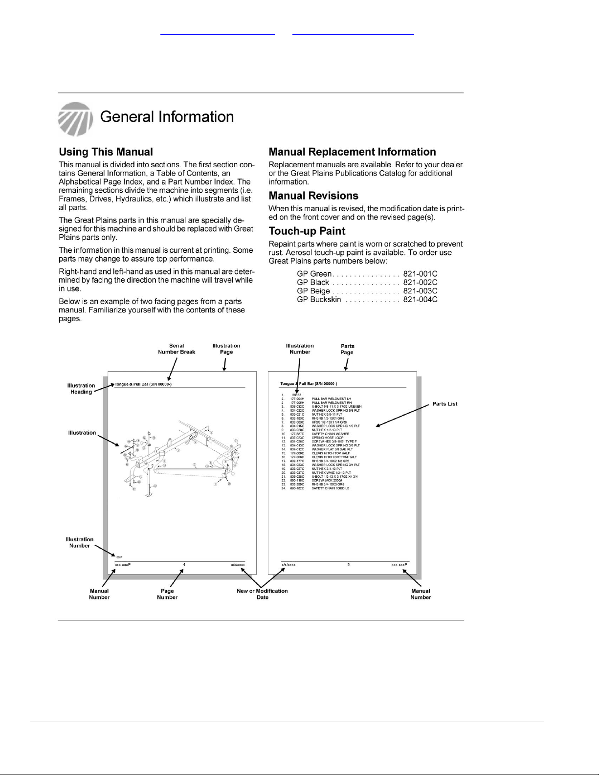
Table of Contents Part Number Index
118-706P - 4 - 05/14/12
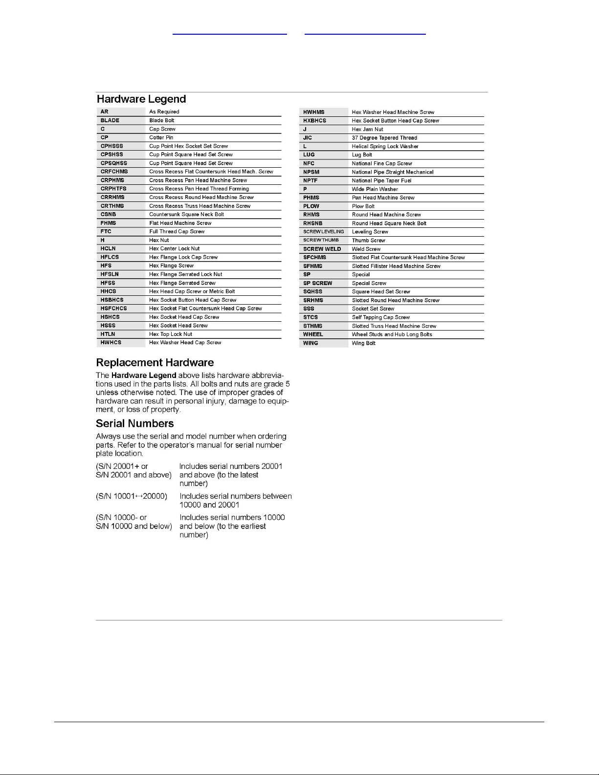
Table of Contents Part Number Index
05/14/12 - 5 - 118-706P
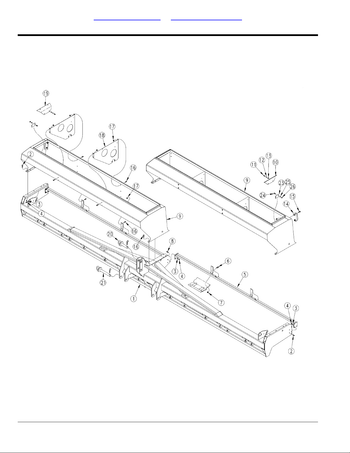
Table of Contents Part Number Index
Box To Frame
(Applies to 2400, 2410, 2420 only)
17507
118-706P - 6 - 05/14/12

Table of Contents Part Number Index
Box To Frame
(Applies to 2400, 2410, 2420 only)
Image No.dwg17507
FRAME 3PT 24'117-045H1.
HHCS 1/2-13X1 1/4 GR5802-034C2.
WASHER LOCK SPRING 1/2 PLT804-015C3.
NUT HEX 1/2-13 PLT803-020C4.
REAR MNT.TB 24'117-046H5.
HFSS 1/4-20X3/4 GR5802-257C6.
NUT HEX LOCK 1/4-20 FLG803-088C7.
HHCS 1/2-13X2 GR5802-128C8.
12' SEED BOX118-415H9.
HHCS 3/8-16X1 1/4 GR5802-079C11.
WASHER LOCK SPRING 3/8 PLT804-013C12.
WASHER FLAT 3/8 USS PLT804-011C13.
HANDLE119-190D14.
HFSS 1/2-13X1 1/2 GR5802-203C15.
HFS 5/16-18X3/4 GR5802-387C16.
NUT HEX FLANGE 5/16-18 PLT803-199C17.
SEED BOX PARTITION118-402D18.
PIN HITCH 1 1/4 X 4 1/2805-119C20.
PIN HITCH 1 7/16 X 8 3/8 PLT805-168C21.
PIN HAIR COTTER .243 WIRE PLT805-167C22.
Box Assembly
RevisionCommentsPart DescriptionPart No.Ref.
1/31/2002 -SEED BOX IDLER COVER LH118-486D10.
1/31/2002 -SEED BOX IDLER COVER RH118-487D19.
2/1/2002 +BEARING CUTOUTCOVER, 47 MST118-403D23.
2/1/2002 +RHSNB 5/16-18X3/4 GR5802-092C24.
2/1/2002 +WASHER LOCK SPRING 5/16 PLT804-009C25.
2/1/2002 +NUT HEX 5/16-18 PLT803-008C26.
05/14/12 - 7 - 118-706P
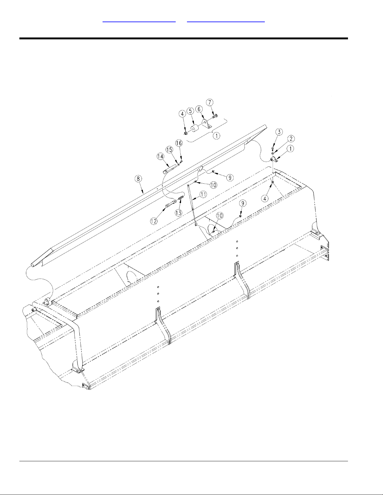
Table of Contents Part Number Index
Lid To Box
(Applies to 2400, 2410, 2420 only)
17508
118-706P - 8 - 05/14/12

Table of Contents Part Number Index
Lid To Box
(Applies to 2400, 2410, 2420 only)
Image No.dwg17508
WASHER FLAT 3/8 USS PLT804-011C2.
HHCS 3/8-16X1 GR5802-017C3.
NUT FLANGE LOCK 3/8-16 PLT803-209C4.
LID HINGE PIVOT313-186D5.
LID HINGE BASE PLATE313-176D6.
RHSNB 3/8-16X2 GR5802-411C7.
LID 126 11/16 SEED119-231H8.
NUT LOCK 5/16-18 PLT803-011C9.
BALL STUD 10MM X 5/16-18 X 1/2800-121C10.
12-20 X 90 LB GAS SPRING890-221C11.
LATCH CASTING MACHINED119-153D12.
SPRING .540 O.D.X 1 1/4 X.054W807-106C13.
LID HANDLE119-154D14.
WASHER FLAT 5/16 SAE PLT804-036C15.
HHCS 5/16-18X1 1/4 NYL802-425C16.
Box Assembly
RevisionCommentsPart DescriptionPart No.Ref.
Includes items 4, 5, 6 and 7.LID HINGE ASSEMBLYPS25120313-076S1.
05/14/12 - 9 - 118-706P

Table of Contents Part Number Index
Lights
(Applies to 2400, 2410, 2420 only)
17542
118-706P - 10 - 05/14/12

Table of Contents Part Number Index
Lights
(Applies to 2400, 2410, 2420 only)
Image No.dwg17542
HANDLE119-190D1.
HFSS 1/2-13X1 1/2 GR5802-203C2.
LIGHT HARNESS, 15' WISHBONE890-648C3.
CABLE TIE .19X14.25 3DIA 50LB800-060C4.
SCR HEX SELF TAP 1/4-20X1TYPEF801-151C5.
12' EWNT LIGHT BRACKET150-138D7.
LIGHT HARNESS, 5' LEAD890-640C8.
NUT HEX FLG. LOCK 1/2-13 PLT.803-169C9.
Box Assembly
RevisionCommentsPart DescriptionPart No.Ref.
Used on LH side.DUAL AG LIGHTS LH890-311C6.
Shown. Used on RH side.DUAL AG LIGHTS RH890-312C6.
05/14/12 - 11 - 118-706P
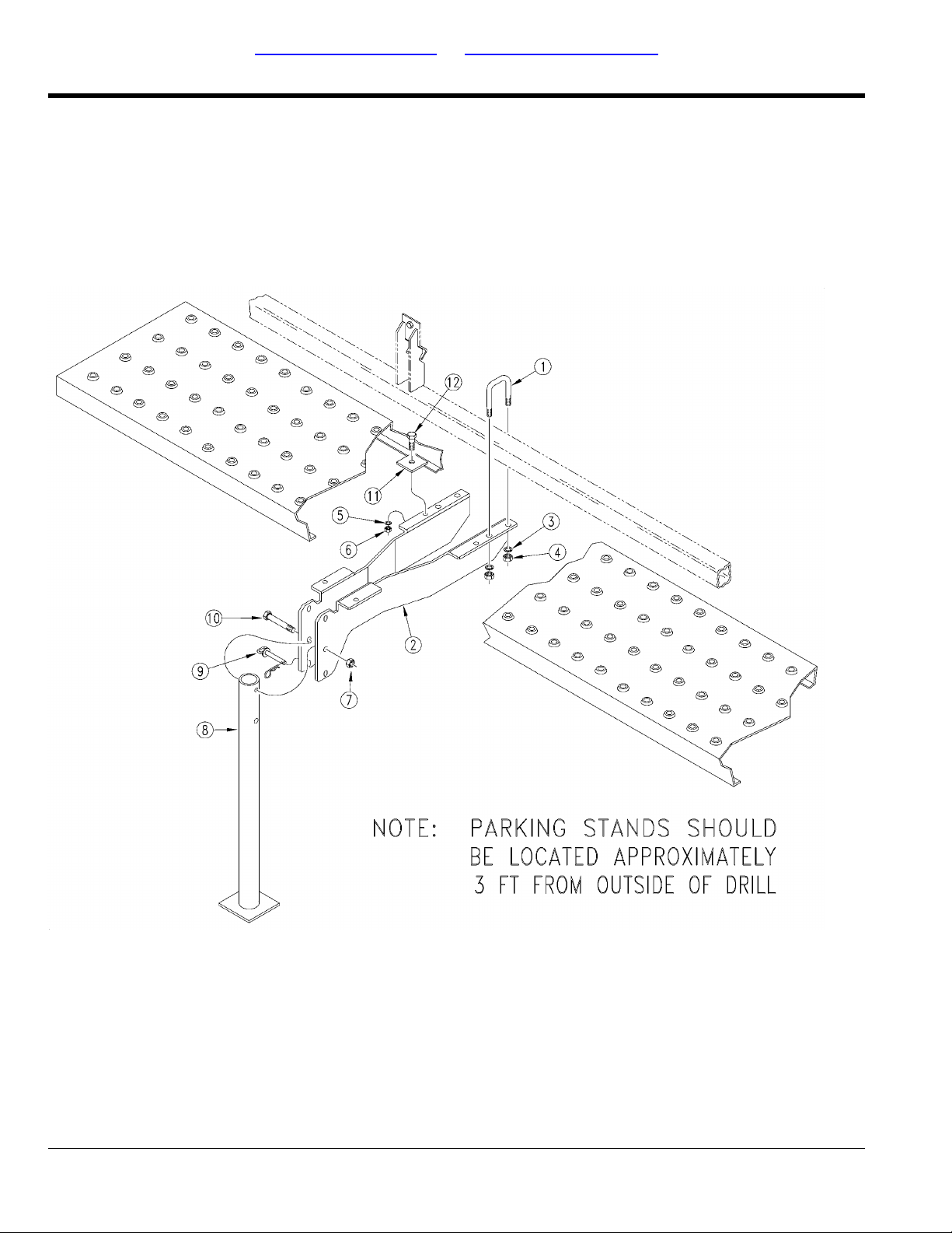
Table of Contents Part Number Index
Parking Stand (Option)
(Applies to 2400, 2410, 2420 only)
17511
118-706P - 12 - 05/14/12

Table of Contents Part Number Index
Parking Stand (Option)
(Applies to 2400, 2410, 2420 only)
Image No.dwg17511
U-BOLT 1/2-13 X 2 X 3 GR 5806-005C1.
STAND MOUNT, FRONT TUBE119-268H2.
WASHER LOCK SPRING 1/2 PLT804-015C3.
NUT HEX 1/2-13 PLT803-020C4.
WASHER LOCK SPRING 3/8 PLT804-013C5.
NUT HEX 3/8-16 PLT803-014C6.
NUT LOCK 1/2-13 PLT803-019C7.
JACK STAND ASSEMBLY119-105H8.
PIN 3/8 X 3 USABLE LW/PIN805-001C9.
HHCS 1/2-13X3 1/2 GR5802-041C10.
3-PT STEP RETAINER119-032D11.
HHCS 3/8-16X1 1/4 GR5802-079C12.
Box Assembly
RevisionCommentsPart DescriptionPart No.Ref.
05/14/12 - 13 - 118-706P
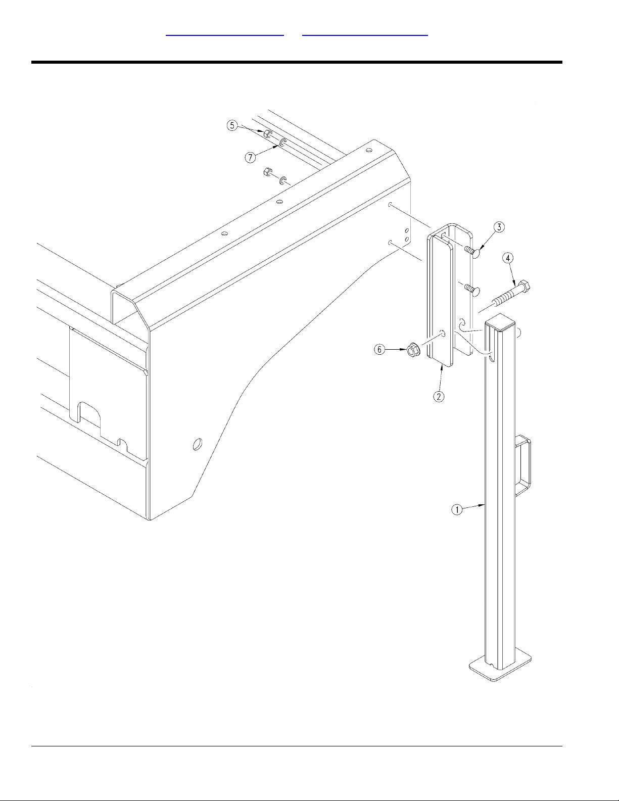
Table of Contents Part Number Index
Rear Parking Stands
(Applies to 2400, 2410, 2420 only)
29018
118-706P - 14 - 05/14/12

Table of Contents Part Number Index
Rear Parking Stands
(Applies to 2400, 2410, 2420 only)
Image No.dwg29018
PARKING STAND WLMT117-179H1.
PARKING STAND MNT WLMT117-180H2.
RHSNB 1/2-13X1 1/2 GR5802-106C3.
HHCS 3/4-10X4 1/4 SPTHD GR 8802-697C4.
NUT HEX 1/2-13 PLT803-020C5.
NUT HEX FLANGE LOCK 3/4-10 PLT803-181C6.
WASHER LOCK SPRING 1/2 PLT804-015C7.
Box Assembly
RevisionCommentsPart DescriptionPart No.Ref.
05/14/12 - 15 - 118-706P
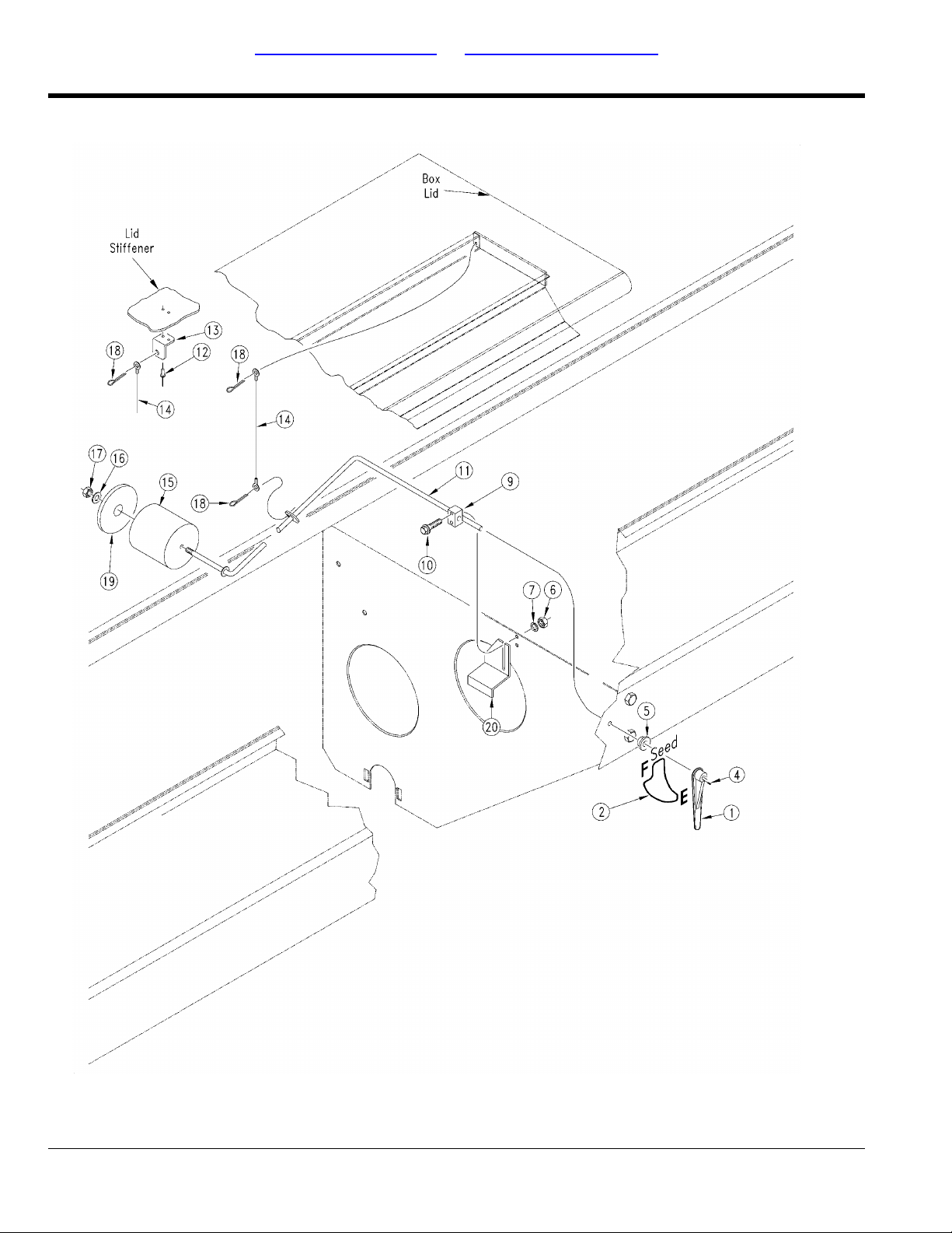
Table of Contents Part Number Index
Seed Level Indicator
(Applies to 2400, 2410, 2420 only)
17509
118-706P - 16 - 05/14/12

Table of Contents Part Number Index
Seed Level Indicator
(Applies to 2400, 2410, 2420 only)
Image no.dwg17509
SEED LEVEL INDICATOR817-350C1.
DECAL LETTER E818-295C3.
SCR HEX HD SHT MET #8 X 1/2801-154C4.
SEED LEVEL BUSHING817-086C5.
NUT HEX 10-24 PLT803-001C6.
WASHER INTERNAL STAR #10 PLT804-004C7.
DECAL LETTER F818-296C8.
SEED LEVEL ARM MOUNT817-202C9.
HFS 10-24 X 1 1/8 PLTD801-096C10.
SEED LEVEL ARM, 6 3/4R. TAB118-474H11.
RIVET POP 1/8X.265LG FLG800-101C12.
SEED LEVEL CHAIN BRACKET197-091D13.
CABLE 3/64 X 11 5/8 W/ EYELETS890-305C14.
FOAM FLOAT197-089D15.
WASHER FLAT 1/4 USS PLT804-075C16.
.00 HEX SS 1/4-20 NYLOCK803-003C17.
PIN COTTER1/8 X 3/4805-067C18.
FOAM FLOAT WASHER197-096D19.
SEED FLOAT DOWN FLOAT STOP118-498D20.
Box Assembly
RevisionCommentsPart DescriptionPart No.Ref.
2nd rev.DECAL SEED LEVEL LH838-237C2.
1st rev.DECAL SEED LEVEL, NOTCHED818-392C2.
No longer available. Order part no.
838-237C.
No longer available. Order part no.
838-237C.
05/14/12 - 17 - 118-706P
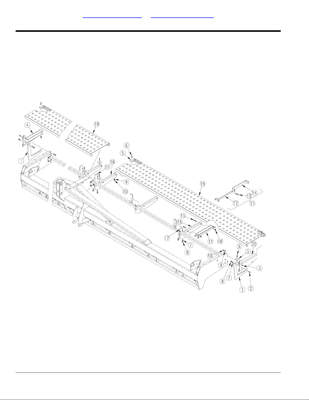
Table of Contents Part Number Index
Walkboard Assembly
(Applies to 2400, 2410, 2420 only)
17510
118-706P - 18 - 05/14/12

Table of Contents Part Number Index
Walkboard Assembly
(Applies to 2400, 2410, 2420 only)
Image No.dwg17510
STEP119-192D1.
HHCS 1/2-13X1 1/2 GR5802-091C2.
HHCS 3/8-16X1 GR5802-017C3.
WALKBOARDEND BRACKET RH119-263H4.
3-PT STEP RETAINER119-032D5.
HHCS 3/8-16X1 1/4 GR5802-079C6.
WASHER LOCK SPRING 1/2 PLT804-015C7.
NUT HEX 1/2-13 PLT803-020C8.
WASHER LOCK SPRING 3/8 PLT804-013C9.
NUT HEX 3/8-16 PLT803-014C10.
OPENER SPRING ADJUST HANDLE198-234L11.
PIN HAIR COTTER .148 WIRE805-032C13.
OPENER HANDLE HOLDER119-211D14.
HFS 3/8-16X1 GR5802-388C15.
WALKBOARDSUPPORT BRACKET119-225D16.
U-BOLT 1/2-13 X 2 X 3 GR 5806-005C17.
NUT FLANGE LOCK 3/8-16 PLT803-209C18.
WALKBOARD3PT 12'119-203D19.
WALKBOARDEND BRACKET LH119-264H20.
Box Assembly
RevisionCommentsPart DescriptionPart No.Ref.
10 Series only.SPRING ADJUSTMENT TOOL WELD198-126H12.
20 Series only.20 SER SEED-LOK HANDLE198-215D12.
05/14/12 - 19 - 118-706P
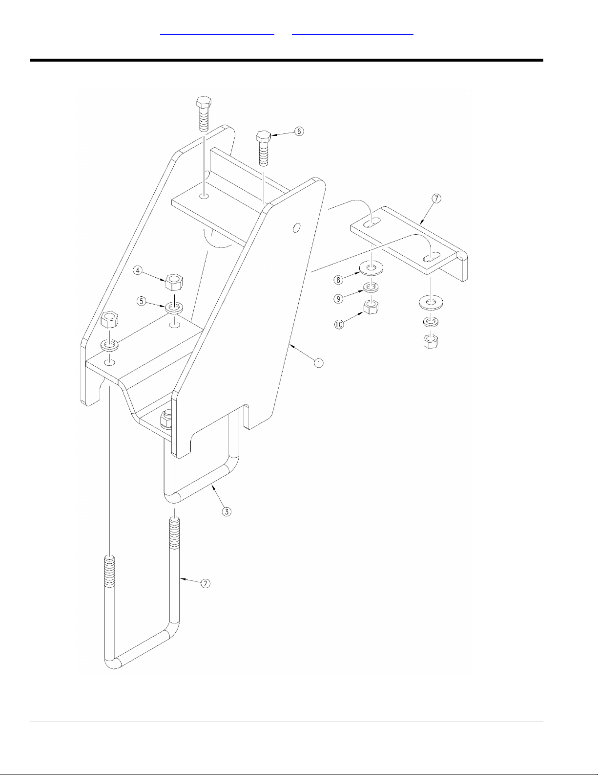
Table of Contents Part Number Index
Weight Bracket
(Applies to 2400, 2410, 2420 only)
24412
118-706P - 20 - 05/14/12

Table of Contents Part Number Index
Weight Bracket
(Applies to 2400, 2410, 2420 only)
Image No.dwg24412
WEIGHT BRACKETWELDMENT-RH118-070H1.
WEIGHT BRACKETWELDMENT-LH118-069H1.
U-BOLT 3/4-10 X 6 1/16 X 9 5/8806-089C2.
U-BOLT 3/4-10 6 1/32 X 7 3/4806-093C3.
NUT HEX 3/4-10 PLT803-027C4.
WASHER LOCK SPRING 3/4 PLT804-023C5.
HHCS 5/8-11X2 1/4 GR5802-057C6.
WEIGHT BRACKETADJ LEG197-062D7.
WASHER FLAT 5/8 USS PLT804-019C8.
WASHER LOCK SPRING 5/8 PLT804-022C9.
NUT HEX 5/8-11 PLT803-021C10.
Box Assembly
RevisionCommentsPart DescriptionPart No.Ref.
05/14/12 - 21 - 118-706P

Table of Contents Part Number Index
Decal Placement
(Applies to 2400, 2410, 2420 only)
17523
118-706P - 22 - 05/14/12

Table of Contents Part Number Index
Decal Placement
(Applies to 2400, 2410, 2420 only)
Image No.dwg17523
DECAL GROUND AND TUBE DISTANCE818-496C2.
DECAL SLOWMOVING VEHICLE818-003C7.
DECAL CAUTION TIRES NOT A STEP818-398C9.
DECAL CAUTION OPERATIONAL MACH818-587C10.
DECAL WARNING 20 MPH TRANS LRG818-188C11.
DECAL WARNING HIGH PRESSUR SML818-339C12.
DECAL GREAT PLAINS W/LOGO818-412C13.
DECAL SEED RATE 1 OF 2838-054C14.
DECAL SEED RATE 2 OF 2838-055C15.
DECAL CAUTION TIRE 36 PSI818-855C16.
DECAL DANGERCRUSH TRCTR & 3PT818-590C17.
DECAL LETTER E818-295C18.
DECAL LETTER F818-296C20.
DECAL 3PT DRIVE TYPE LH VIEW818-886C21.
DECAL 3PT DRIVE TYPE RH VIEW818-885C22.
DECAL SCRIPT SOLID STAND SMALL838-158C23.
Decals
RevisionCommentsPart DescriptionPart No.Ref.
2000 and BelowDECAL AMBER REFLECTOR818-229C1.
2000 and belowDECAL RED REFLECTOR818-230C3.
2nd rev.2000 and above.DECAL GREAT PLAINS ON LOGO SML838-228C4.
1st rev.1999 and below.DECAL GREAT PLAINS ON LOGO818-413C4.
2nd rev.2000 and above.DECAL LOGO&GP F/STRIPE 4 X 24838-161C5.
1st rev.Not shown. 1999 and below.DECAL GP W/ LOGO AND STRIPE818-415C5.
2nd rev.2000 and above.DECAL 3 COLOR STRIPE 2.50 WIDE838-160C6.
1st rev.1999 and below.DECAL W/ 4 COLOR STRIPE818-414C6.
2nd rev.2000 and above.DECAL 2400838-232C8.
1st rev.1999 and below.DECAL SOLID STAND 2400818-879C8.
2nd rev.2000 and above.DECAL 2410838-233C8.
1st rev.1999 and below.DECAL SOLID STAND 2410818-880C8.
2nd rev.2000 and above.DECAL 2420838-188C8.
1st rev.1999 and below.DECAL SOLID STAND 2420818-881C8.
No longer available. Order part no.
838-237C.
2nd rev.DECAL SEED LEVEL LH838-237C19.
1st rev.DECAL SEED LEVEL, NOTCHED818-392C19.
No longer available. Order part no.
838-237C.
2001 and above.DECAL REFLECTORRED 1 1/2X9838-266C24.
2001 and above.DECAL REFLECTORAMBER 1 1/2X9838-265C25.
05/14/12 - 23 - 118-706P
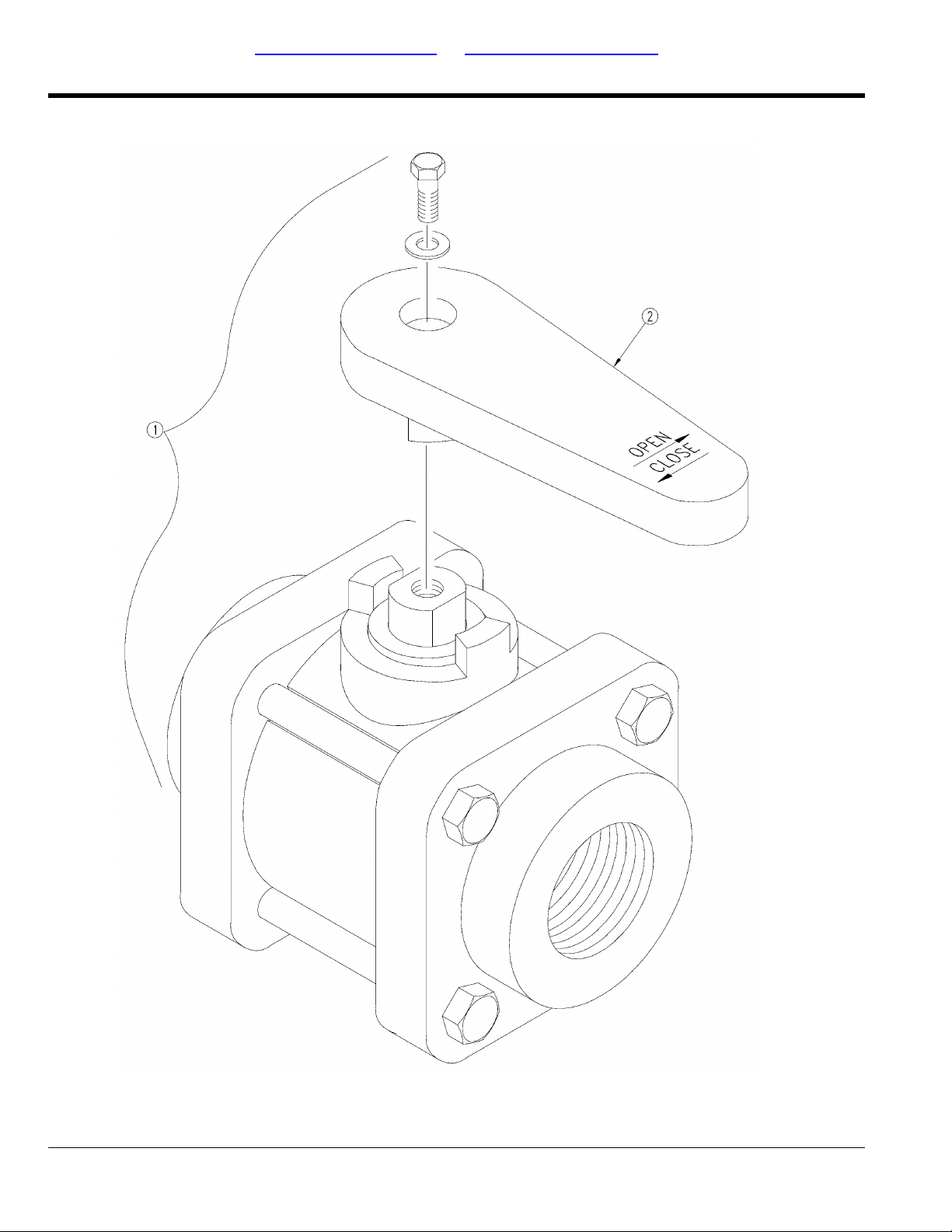
Table of Contents Part Number Index
Ball Valve
(Applies to 2400, 2410, 2420 only)
14407
118-706P - 24 - 05/14/12

Table of Contents Part Number Index
Ball Valve
(Applies to 2400, 2410, 2420 only)
Image No.dwg14407
VALVE - 1FNPT BALL POLYPROP829-011C1.
BANJO VALVE HANDLE 1/2-1V-071532.
Drill Boom
RevisionCommentsPart DescriptionPart No.Ref.
05/14/12 - 25 - 118-706P
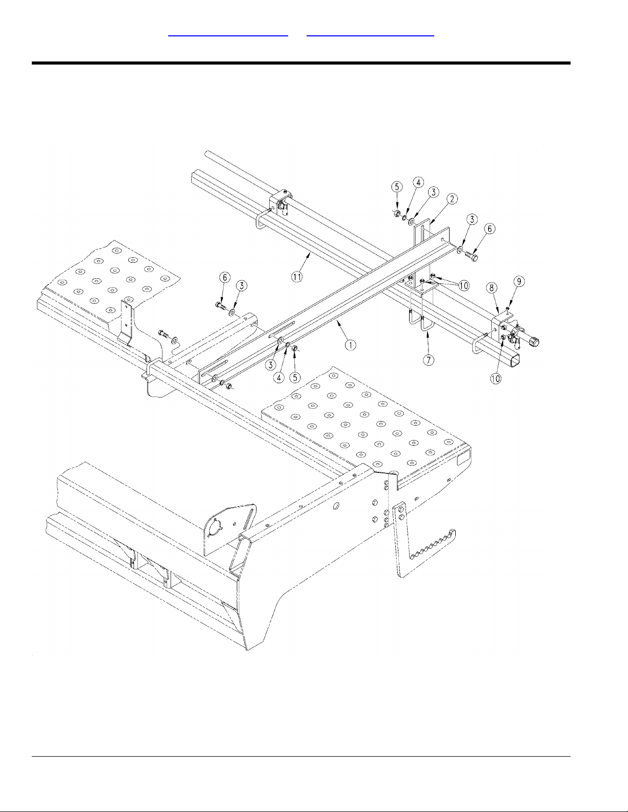
Table of Contents Part Number Index
Drill Boom Mounting
(Applies to 2400, 2410, 2420 only)
18177
118-706P - 26 - 05/14/12

Table of Contents Part Number Index
Drill Boom Mounting
(Applies to 2400, 2410, 2420 only)
Image No.dwg18177
HANGER MOUNT116-222D1.
3PT HANGER WELDMENT116-197H2.
WASHER FLAT 3/8 USS PLT804-011C3.
WASHER LOCK SPRING 3/8 PLT804-013C4.
NUT HEX 3/8-16 PLT803-014C5.
HHCS 3/8-16X1 1/4 GR5802-079C6.
U-BOLT 5/16-18 X 1 17/32X2 1/8806-107C7.
NOZZLE BRACKET116-214D8.
NUT HEX WHIZ 1/4-20 18-8 SS803-187C9.
NUT HEX FLANGE 5/16-18 PLT803-199C10.
Drill Boom
RevisionCommentsPart DescriptionPart No.Ref.
Left hand.24' LH BOOM MOUNT TUBE116-219D11.
Right hand.24' RH BOOM MOUNT TUBE116-220D11.
05/14/12 - 27 - 118-706P
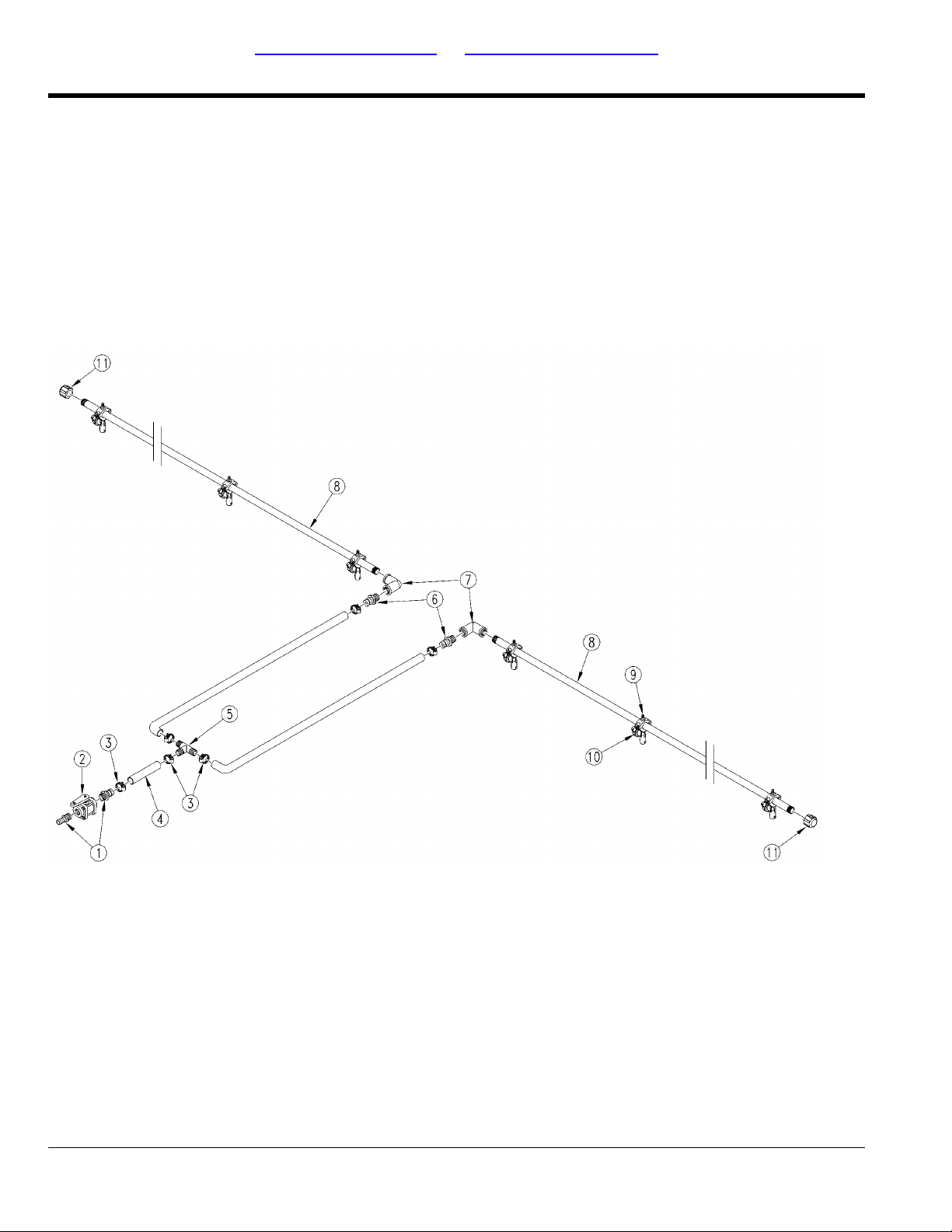
Table of Contents Part Number Index
Drill Boom Plumbing
(Applies to 2400, 2410, 2420 only)
18176
118-706P - 28 - 05/14/12

Table of Contents Part Number Index
Drill Boom Plumbing
(Applies to 2400, 2410, 2420 only)
Image No.dwg18176
AD 1MNPT X 1HB POLYPROP830-087C1.
CLAMP WRM DRV #12 SS(.56-1.25)800-127C3.
HOSE 1 ID 200PSI EPDM990-082R4.
TEE 1HB POLYPROP830-013C5.
AD 3/4MNPT X 1HB POLYPROP830-085C6.
EL 3/4FNPT POLYPROP830-034C7.
HHCS 5/16-18X1 1/2 GR5802-012C9.
NOZZLE BODY 3/4 WET BOOM CLAMP829-089C10.
CA 3/4FNPT POLYPROP830-061C11.
Drill Boom
RevisionCommentsPart DescriptionPart No.Ref.
Refer to "Ball Valve" for breakdown.VALVE - 1FNPT BALL POLYPROP829-011C2.
Left hand.126 WET BOOM TUBE116-217D8.
Right hand.146 WET BOOM TUBE116-218D8.
Refer to "Spraying Systems Check
Valve (829-089C)" for breakdown.
05/14/12 - 29 - 118-706P
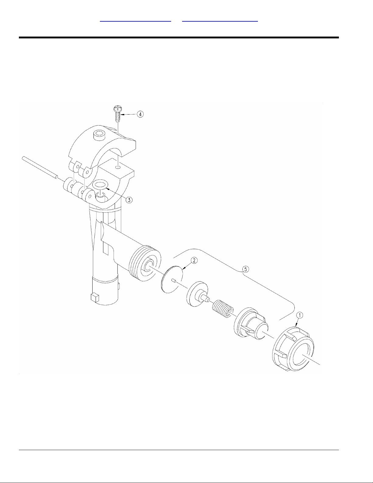
Table of Contents Part Number Index
Spraying Systems Check Valve (829-089C)
(Applies to 2400, 2410, 2420 only)
16714
118-706P - 30 - 05/14/12
 Loading...