

Page 1
Great Plains Mfg., Inc.
Installation Instructions
3-Point Precision Seeding System
Marker Option
Used with:
• 2410P and 2420P
General Information
When you see this symbol, the subsequent instructions and
warnings areserious- follow without exception. Your life and
!
!
the lives of others depend on it!
Theseinstructions explainhowtoinstallthe MarkerOptionon the 24 foot3-point Precision Seeding
Systems.
The markers fold and unfold hydraulically for field
operation. The marker disks leavea linefor the
drill operator to followon thenextfieldpass.Markersaremountedonthe drillframe and requiretwo
hydraulic remote valves on the tractor. Asequence valve is available so markerscan be
operated on one hydraulic circuit.
These instructions apply to:
113-729A 24P Dual Marker Package
Assembly Instructions
Marker Assemble
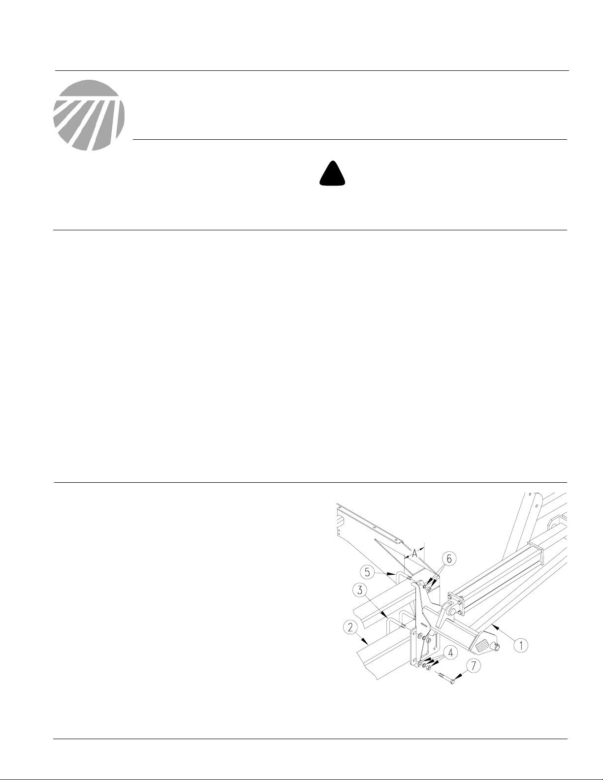
Refer to Figure 1.
Manual Update
Refer to the 3-Point Precision Seeding System
operator’smanual for detailed information on
safely operating, adjusting, troubleshooting and
maintaining the Marker Option. Refer to theparts
manual for part identification.
118-769M 2410P and 2420P Operator’s
Manual
118-769P 2410P and 2420P Parts Manual
Before You Start
Page7is a detailed listing ofpartsincluded in the
Marker Option package. Use this list toinventory
parts received.
24 foot A = 11 1/2 inches
1. Lowerdrill into fieldposition. Allow 13feet on
each end of a 24-foot drill.
2. Mount first marker section (1) on drill 7 x 5
inchframe tube(2).Mount markerattheend of
thedrillusingdimension"A" asastartingpoint.
3. Secure markersection with 5/8 inch u-bolts
(3), lock washers, washers and nuts (4). and
1/2inchu-bolts(5),lockwashers and nuts(6).
NOTE: On the 24-foot drill with 7 1/2" inch row
spacing, the last two openers are bolted to the
marker mount using 5/8x 61/2 inch straight bolts
(7).
© Copyright 2000 Printed
3/21/2001
Figure 1
First Marker Section Assembly
18413
113-742M
Page 2
Marker Option
2
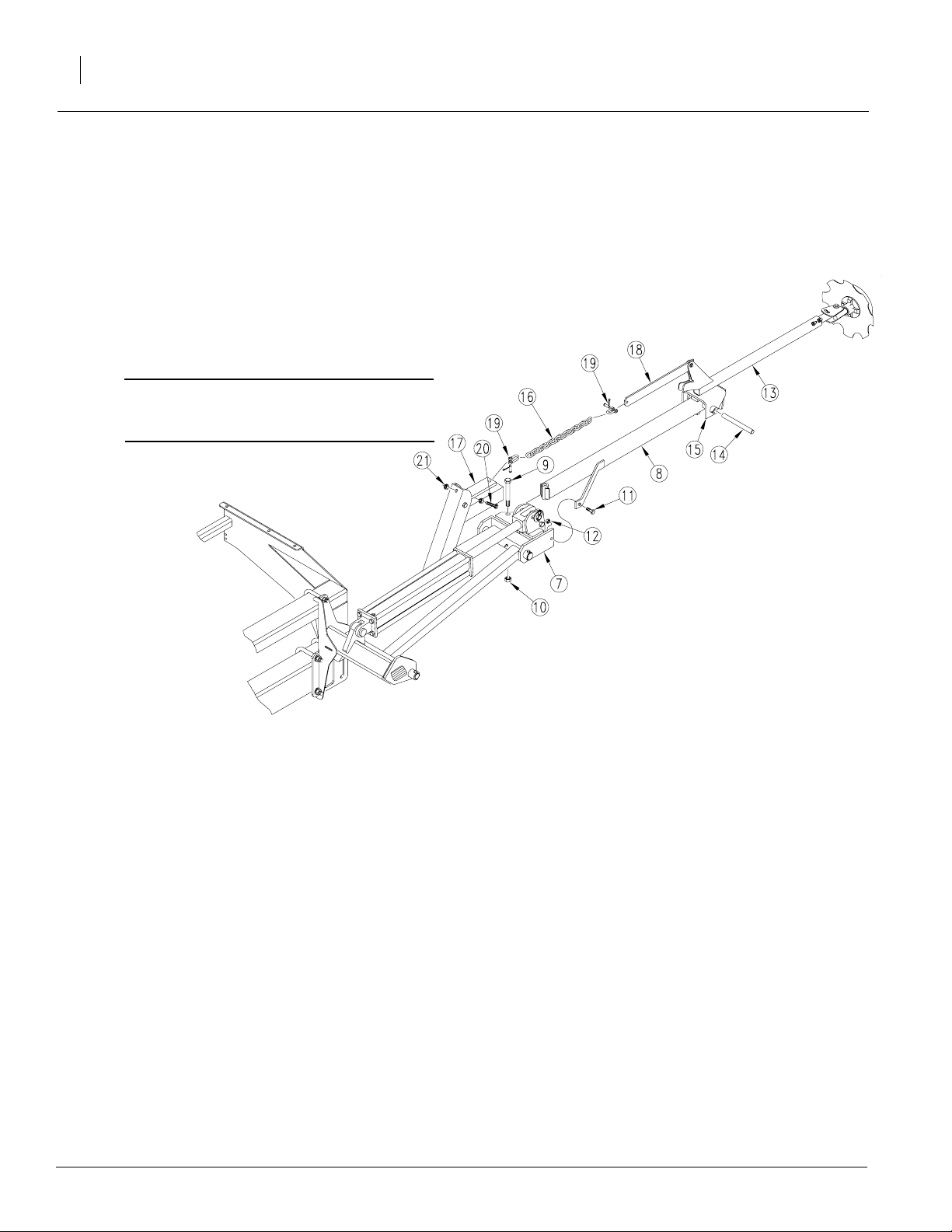
Refer to Figure 2
4. Remove port plugs on cylinder and carefully
5. Align holes of break-away section (8) with
Great Plains Mfg., Inc.
unfold first marker section. Rotate hinge section (7) into a horizontal position.
holes in hingesection. Bolt sectionstogether
using a 5/8-inch pivotbolt (9),locknut (10), 3/
8-by-1 3/4-inch, grade 2 shear bolt (11) and
lock nut (12).
IMPORTANT: Be sure shear bolt is a grade 2
bolt. Failure to use a gr ade 2 bolt can cause
marker damage.
Marker Breakaway Assembly
6. Place third marker sections (13) over end of
second section (8) and insert hinge pin
through second and third section pivot (14)
with the 1/4 X 2 inch bolt and lock nut.*
7. Connect markerchain (16)to chainbar (17)
and chain pivot (18) with utility clevis(19).
With markerdisk adjustedto seedingwidth
and disk touching the ground, remove chain
slack with utility clevis (19) nearest drill.*
8. Assemblefull-threaded 3/8 inch stop bolt (20)
andlocknut(21)onlift armextensionso head
of stop bolt extendsas littleas possible. After
themarker is bled and folded, adjust stop bolt
to remove slackfrom chain.*
9. Repeat steps for other marker.
10. To adjust markers, refer toMarker Adjust-
ments in the operator’s manual.
*NOTE: Parts are located in bolt bag.
Figure 2
19207
113-742M 4/9/2004
Page 3
Great Plains Mfg., Inc.
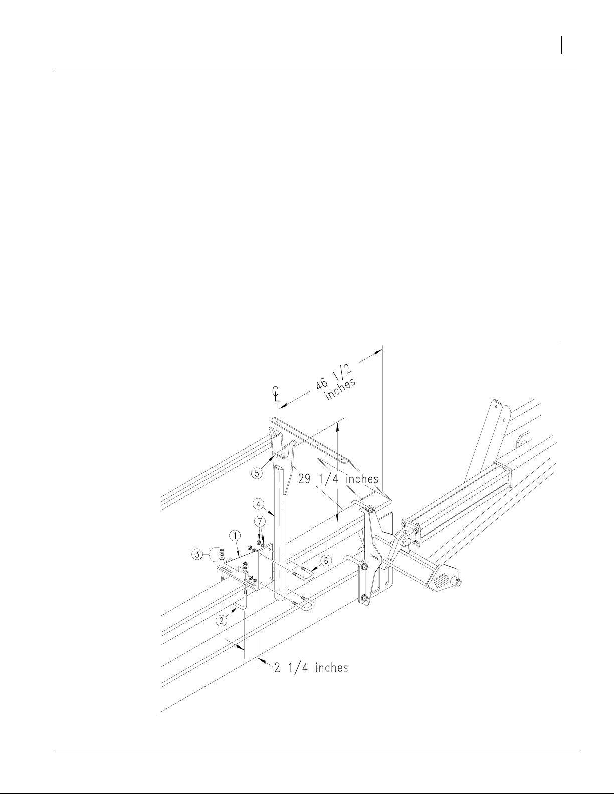
Carrier Assembly for 24P drill
To assemble carrier ontodrill frame, refertoFigure 3.
1. Assemble transport-carrier mount (1) on drill
frame. Center mount 46 1/2inches from outside
end of drill frame. Use 1/2 x 6 1/32 x 7-inch ubolts(2), flat washers,lock washersandhexnuts
(3). Slide mount forward so its leading edge is
about 2 1/4 inches ahead of front edge of drill
frame tube.
2. Bolt transport carrier (4) to transport-carrier
mount so top surface of saddle (5) is about
29 1/4 inches above top of drill frame tube. Secure transport carrier with 1/2x2x3-inch
u-bolts (6), lock washers and hex nuts (7).
3. After installing and bleeding hudraulics, transport carrier may require further adjustment.
When folded, the second marker section should
rest in the transport-carrier saddle..
Installation Instructions
3
4/9/2004
Figure 3
19208
Carrier Assembly
113-742M
Page 4

Marker Option
4
4. After installing and bleeding hydraulics, trans-
Installing Marker Hydraulics
Without Sequence Valve
Refer to Figure 4.
1. Install elbow fittings (1) in cylinder ports.
2. At rod end ofeach cylinder, installan adaptor
Great Plains Mfg., Inc.
port carrier may require further adjustment.
When folded, the second marker section
should rest in the transport-carrier saddle.
(2) into elbow fitting. Installaneedle valve(3)
in adaptor.
3. Connect hydraulic hosesto fittings and route
hydraulic hoses to tractor outlets.Route hydraulichoses throughtransport-carrier mount
at cutout. Use black cableties tosecure hydraulic hoses to drill frame.
4. Usingorange cableties, secureaplastic hose
label, see Figure 5, to each pair of hydraulic
hoses near tractor outlets.
5. Proceed with "Bleeding MarkerHydraulics"
on page 5.
Needle Valve Assembly
Plastichose
label
Figure 4
Cable tie
17642
Figure 5
Hose label and cable tie
113-742M 4/9/2004
17641
Page 5

Great Plains Mfg., Inc.
With Sequence Valve
Refer to Figure 6.
1. Mount sequence valve (1) 810-197C on drill
usingmountingplate(2)113-488D.Bolt plate
to inside end of left-hand-box panel (3) using
one1/2-inchhexbolt (4). The sequencevalve
and mounting plate can be purchased seper
ately from your Great Plains Dealer.
2. Bolt valve(1) to mountingplate (2)with two 3/
8 x 3/4-inch hex bolts and lock washers (5).
3. Install elbow fittings in cylinderports.Discard
adaptorfitting andtwoneedle valvesprovided
in markerkit.
4. Use hoses provided toconnect valve ports to
cylinders. Refer to Figure 7 for port connections .(1) 811-440C and (2) 811-169C, dealer
and customer must order these seperately.
Installation Instructions
5
5. Connectyourown hydraulichoses to ports on
front of valve.Route hoses to tractor outlets.
6. Using orange cable tie, secure plastic hose
label, see Figure 5, to hydraulic hoses near
tractor outlets.
7. Proceed with "Bleeding MarkerHydraulics"
on page 5.
Figure 7
Hydraulic Hose Connection
Figure 6
Sequence Valve Assembly
18416
4/9/2004
19209
Bleeding Marker Hydraulics
113-742M
Page 6

Marker Option
6
You may be injured if hit by a folding or unfolding
marker. Markers may fall quickly and unexpectedly if
the hydraulics fail. Never allow anyone near the drill
when folding or unfolding the markers.
Escaping fluid under pressurecan have sufficient pressure to penetrate the skin. Check all hydraulic lines
and fittings before applying pressure. Fluid escaping
froma very smallhole can bealmost invisible. Use paper or cardboard, not body parts, and wear heavy
gloves to check for suspected leaks. If injured, seek
medical assistance from a doctor that is familiar with
this type of injury. Foreign fluids in the tissue must be
surgically removed within a few hours or gangrene
will result.
!
CAUTION!
!
WARNING!
Great Plains Mfg., Inc.
1. Check that tractor hydraulic reservoir is full.
2. With both markerslowered into fieldposition,
loosenhydraulic-hosefittings at rod and base
endsof marker cylinders.If applicable,loosen
fittings on back side of sequence valve.
IMPORTANT: Neverbleedan O-ring fitting.Instead, bleed a nearby pipe or JIC fitting.
3. With tractor idling, activate tractor hydraulic
valveuntil oilseeps outarounda loosened fitting. Tighten that fitting.
IMPORTANT: JIC fittings do not require high
torque. JIC and O-ring fittings do not require
sealant. Always use liquid pipe sealant when
adding or replacing pipe-thread fittings. To
avoid crac king hydraulic fittings from over
tightening, do not use plastic sealant tape.
4. Reactivate tractor hydraulic valve until oil
seeps out around another loosened fitting.
Tighten that fitting. Repeat process until all
loosened fitting have been bledand tightened.
5. Adjust markerfolding to a safe speed. Refer
to "MarkerAdjustments" inthe operator’s
manual.
113-742M 4/9/2004
Page 7

Great Plains Mfg., Inc.
113-729A MARKER, 3PT 24P DUAL
Your kit includes:
Qty. Part No. Part Description
1 113-740K MARKER BUNDLE 24-P 3PT DUAL
1 113-180H LH FIRST SECTION
1 113-181H LIFT LUG CHANNEL LH
1 113-183H 30’ FF MARKER 3RD SECTION
1 113-188H RH FIRST SECTION
1 113-189H LIFT LUG CHANNEL RH
2 113-195H 3 SECTION MARKER BREAKAWAY
1 113-196H 24’ FF MARKER 3RD SECTION
2 113-200H CHAIN BAR WELDMENT
2 113-248D PIN 1 OD X 4.34 USABLE.
2 113-311D HINGE PIN
2 113-312D FIRST PIVOT SHAFT
2 113-313D SECOND PIVOT SHAFT
2 113-323D CHAIN BAR
2 113-324D CYLINDER STOP
4 113-325D STOP BUSHING
1 113-352D MARKER TUBE 30 LONG
1 113-354D 13’ MARKER TUBE 46 1/2 LONG
2 113-560H MARKER CARRIER
2 113-563S MARKER DISC & HUB ASSEMBLY
2 113-568H MARKER TRANSPORT MOUNT
1 113-689H MARKER MOUNT LH
1 113-690H MARKER MOUNT RH
6 800-001C GREASE ZERK STRAIGHT 1/4-28
4 801-054C SCREW SET SQ HD 1/2-13X1 GR5
2 802-022C HHCS 3/8-16X1 1/2 GR5
4 802-039C HHCS 1/2-13X3 GR5
6 802-115C HHCS 5/16-18X2 GR5
2 802-168C HHCS 5-16-18X2 GR5
2 802-249C HHCS 1/2-13X4 1/2 GR5 SPTHD
2 802-254C HHCS 5/8-11X5 1/2 GR5
2 802-261C HHCS 3/8-16X2 GR5 FTHD
2 802-266C HHCS 3/8-16X2 GR2
6 803-011C NUT LOCK 5/16-18 PLT
10 803-013C NUT LOCK 3/8-16 PLT
2 803-019C NUT LOCK 1/2-13 PLT
12 803-020C NUT HEX 1/2-13 PLT
2 803-024C NUT LOCK 5/8-11 PLT
4 803-036C NUT HEX JAM 1/2-13 PLT
4 804-011C WASHER FLAT 3/8 USS PLT
12 804-015C WASHER LOCK SPRING 1/2 PLT
8 804-017C WASHER FLAT 1/2 USS PLT
4 804-029C WASHER FLAT 1 SAE
4 805-058C PIN COTTER 3/16 X 2
2 806-005C U-BOLT 1/2-13 X 2 X 3 GR 5
1 810-118C CYL 2.5X20X1.12 ROD (TIE) 1
2 818-229C DECAL AMBER REFLECTOR
4 818-682C DECAL WARNING PINCH/CRUSH MRKR
6 803-011C NUT LOCK 5/16-18
4 803-021C NUT HEX 5/8-11 PLT
Installation Instructions
7
113-742M4/9/2004
Page 8

Marker Option
8
113-729A MARKER, 3PT 24P DUAL
Your kit includes:
Qty. Part No. Part Description
1 113-741K MARKER HRDWR 24P DUAL
2 113-328D 24’ MARKER CHAIN
1 113-351D MARKER TUBE 42 LG
12 800-082C CABLE TIE .31X21.5 6 DIA 120
2 800-300C CABLE TIE 2 DIA MIN - ORG
4 802-335C HHCS 5/8-11X6 1/2 GR5
12 803-020C NUT HEX 1/2-13 PLT
8 803-021C NUT HEX 5/8-11 PLT
12 804-015C WASHER LOCK SPRING 1/2 PLT
8 804-017C WASHER FLAT 1/2 USS PLT
8 804-021C WASHER FLAT 5/8 SAE PLT
8 804-022C WASHER LOCK SPRING 5/8 PLT
4 806-053C U-BLOT 5/8-11X7 1/32X6
4 806-159C U-BOLT 1/2-13 X 5 1/32 X 4
2 810-058C VAVLE 3/8 NEEDLE
2 811-044C AD 3/8MNPT
2 811-281C EL 3/8FNPT 9/16MORB
2 817-348C PLASTIC HOSE LABEL
4 890-018C 5/16X1 1/4 UTILITY CLEVIS
1 113-742M MANUAL MARKERS 24-P 3PT
Great Plains Mfg., Inc.
1 113-624V 24’ 3PT DUAL MARKER HOSE BUNDLE
2 811-129C HH1/4R1 234 3/8MNPT 1/2MNPT
2 811-297C SP HH1/4R1 212 3/8MNPT-W/AD
4/9/2004
113-742M
 Loading...