

Page 1
Great Plains Mfg., Inc.
Installation Instructions
24 Series Drills
Folding Markers
Used with:
2400
•
2410
•
2420
•
When you see this symbol, the subsequent instructions and
warnings are serious - follow without exception. Your life and
!
!
the lives of others depend on it!
General Information
These instructions explain how to install the optional markers.
The markers fold and unfold h ydraulically for field oper ation. The
marker disks leave a line f or the drill operator to follow on the next
field pass. Markers are mounted on the drill frame and require
two hydraulic remote valves on the tractor. A sequence v alve is
available so markers can be oper ated on one hydraulic circuit.
These instructions apply to:
113-662A 24FT 3PT DUAL MARKERS
113-466A 94 3PT SEQ V ALVE KIT-FIELD
Manual Update
Refer to the drill operator’ s manual for detailed information on
safely operating, adjusting, troubleshooting and maintaining the
markers. Refer to the parts manual for part identification.
• 2400, 2410 and 2420 Operator’s Manual. . . . . . .118-706M
• 2400, 2410 and 2420 Parts Manual. . . . . . . . . . 118-706P
Before You Start
Starting on page 4 are detailed listings of parts included in
the option packages. Use these lists to in v entory parts received.
Assembly Instructions
Marker Assembly
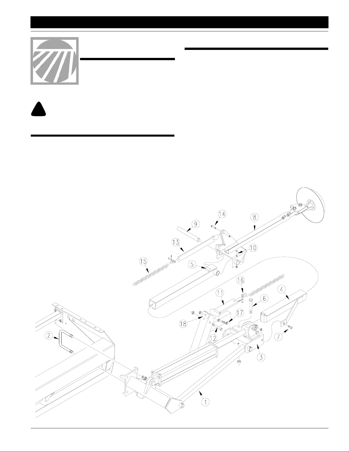
Refer to Figure 1.
1. Lower drill into field position. Allow 15 feet of clearance from
each end of drill box for marker assembly.
2. Attach first marker section (1) to drill frame. Mount marker
as far out on drill frame as possible. Secure marker to drill
frame with 5/8-inch u-bolts (2), lock washers and he x nuts .
3. Remove port plugs from marker cylinder and carefully unfold first marker section. Rotate hinge (3) into a horizontal
position.
4. Assemble second marker section (4) onto first section so
that stop block (5) on second section faces up. Secure sec
tions with 5/8-inch bolt (6) and lock nut and 3/8-by-2-inch,
grade 2 shear bolt (7) and lock nut.
IMPORTANT: Use a grade 2 bolt for the shear bolt or marker
damage will occur during field operation.
5. Place third marker section (8) over end of second section
and insert hinge pin (9) through second- and third-section
pivot. Secure hinge pin with the 1/4-by-2-inch bolt (10) and
lock nut.
6. Bolt chain pivot (11) to first marker section with 3/8-by-3 1/4inch bolt (12) and lock nut so chain pivot piv ots freely on bolt.
7. Bolt chain bar (13) to third marker section
with the 3/8-by-1 1/2-inch bolt (14) and
lock nut so chain bar pivots freely on bolt.
-
Figure 1
Marker Assembly
17628
© Copyright 1998 Printed 11/25/98
8. Connect
marker
chain
(15) to
chain bar
and chain
pivot with utility
clevis (16). With
marker disk adjusted
for seeding width and
ground, remove chain slack with
utility clevis nearest drill.
9. Assemble full-threaded, 3/8-inch stop bolt
(17) and lock nuts on lift-arm extension (18) so
head of stop bolt extends as little as possible.
After the marker is bled and folded, adjust stop
bolt to remove slack from chain. Ref er to Mark
er Chain Adjustments, "Adjustments" in the
operator’s manual.
disk touching the
113-672M
-
1
Page 2
Assembly
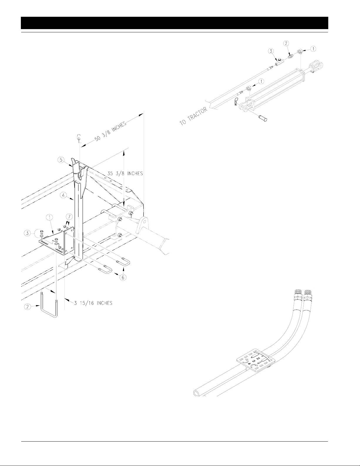
Transport Carrier Assembly
Refer to Figure 2.
1. Assemble transport-carrier mount (1) on drill frame. Center
mount 50 3/8 inches from outside end of drill frame. Use
1/2-by-6 1/32-by-7-inch u-bolts (2), flat washers, loc k w ashers and hex nuts (3). Slide mount forw ard so its leading edge
is about 3 15/16 inches ahead of front edge of drill frame
tube.
2. Bolt transport carrier (4) to transport-carrier mount so top
surface of saddle (5) is about 35 3/8 inches above top of drill
frame tube. Secure transport carrier with 1/2-by-2-by-3-inch
u-bolts (6), lock washers and hex nuts (7).
Great Plains Mfg., Inc.
17642
Figure 3
Assemble Needle Valves
3. Connect hydraulic hoses to fittings and route hydr aulic hoses to tractor outlets. Route hydraulic hoses through trans port-carrier mount at cutout. Use black cable ties to secure
hydraulic hoses to drill frame.
4. Using orange cable ties, secure a plastic hose holder to
each pair of hydraulic hoses near tractor outlets. See
4.
5. Proceed with "Bleeding Marker Hydraulics," page 3.
With Sequence Valve
Refer to Figure 5.
1. Mount sequence valve (1) on drill using mounting plate (2).
See Figure 5. Bolt plate to inside end of left-hand-bo x panel
(3) using one 1/2-inch hex bolt (4).
2. Bolt valve to mounting plate with two 3/8-b y-3/4-inch hex
bolts and lock washers (5).
3. Install elbow fittings in cylinder ports. Discard adaptor fitting
and two needle valves pro vided in marker kit.
4. Use hoses provided to connect valve ports to cylinders. Refer to Figure 5 for port connections.
5. Connect your own hydr aulic hoses to ports on front of valve.
Route hoses to tractor outlets.
6. Using orange cable tie, secure plastic hose label to h ydraulic hoses near tractor outlets. See Figure 4.
Figure
17629
Figure 2
Transport Carrier Assembly
3. After installing and bleeding hydraulics, tr ansport carrier
may require further adjustment. When folded, the second
marker section should rest in the transport-carrier saddle
and be parallel with the drill box. Refer to Marker Adjust-
ments, "Adjustments" in the operator’ s manual.
Installing Marker Hydraulics
Without Sequence Valve
Refer to Figure 3.
1. Install elbow fittings (1) in cylinder ports.
2. At rod end of each cylinder, install an adaptor (2) into elbow
fitting. Install a needle valve (3) in adaptor.
7. Proceed with "Bleeding Marker Hydraulics," page 3.
24 Series Drills Folding Markers 113-672M 4/9/04
2
Figure 4
Install Hose Label
17641
Page 3

Great Plains Mfg., Inc.
Assembly
17631
Figure 5
Mount Sequence Valve
Bleeding Marker Hydraulics
!
CAUTION!
You may be injured if hit by a folding or unfolding marker. Markers
may fall quickly and unexpectedly if the hydraulics fail. Never allow
anyone near the drill when folding or unfolding the markers.
!
WARNING!
Escaping fluid under pressure can have suf ficient pr essure to penetrate
the skin. Check all hydraulic lines and fittings before applying pressure. Fluid escaping from a very small hole can be almost invisible.
Use paper or cardboard, not body parts, and wear heavy gloves to
check for suspected leaks. If injured, seek medical assistance from a
doctor that is familiar with this type of injury. Foreign fluids in the tis
sue must be surgically remo ved within a few hours or gangrene will result.
1. Check that tractor hydraulic reservoir is full.
2. With both markers lowered into field position, loosen hy-
draulic-hose fittings at rod and base ends of marker cylinders. If applicable, loosen fittings on back side of sequence
valve.
IMPORTANT: Never bleed an O-ring fitting. Instead, bleed
a nearby pipe or JIC fitting.
3.
With tractor idling, activate tractor hydr aulic valve until oil
seeps out around a loosened fitting. Tighten that fitting.
IMPORTANT: JIC fittings do not require high torque. JIC
and O-ring fittings do not require sealant. Always use liquid
pipe sealant when adding or replacing pipe-thread fittings.
T o a void cr acking h ydraulic fittings from ov er tightening, do
not use plastic sealant tape.
4. Reactivate tractor hydraulic v alv e until oil seeps out around
-
another loosened fitting. Tighten that fitting. Repeat process
until all loosened fitting have been bled and tightened.
5. Adjust marker folding to a safe speed. Refer to Marker Ad-
justment, "Adjustments," in the operator’ s manual.
4/9/04
24 Series Drills Folding Markers 113-672M
3
Page 4

Great Plains Mfg., Inc.
Listing of Parts
113-662A 24Ft 3Pt Dual Markers
Your Kit Includes:
Qty. Part No. Part Description
2 811-129C HH1/4R1 234 3/8MNPT 1/2MNPT
2 811-297C SP HH1/4R1 212 3/8MNPT-W/AD
1 113-180H LH FIRST SECTION
1 113-181H LIFT LUG CHANNEL LH
1 113-188H RH FIRST SECTION
1 113-189H LIFT LUG CHANNEL RH
1 113-192H LH SECOND SECTION
1 113-195H RH SECOND SECTION
2 113-196H 24’ F.F. MKR. 3RD. SECTION
2 113-248D PIN 1 OD X 4.34 USABLE
2 113-312D FIRST PIVOT SHAFT
2 113-313D SECOND PIVOT SHAFT
2 113-324D CYLINDER STOP
4 113-325D STOP BUSHING
2 113-352D MARKER TUBE 30 LG
1 113-558H MARKER, L.H. MOUNT 96
1 113-559H MARKER, R.H. MOUNT 96
2 113-563S MARKER DISC & HUB ASSEMBLY
6 800-001C GREASE ZERK STRAIGHT 1/4-28
4 801-054C SCREW SET SQ HD 1/2-13X1 GR
4 802-039C HHCS 1/2-13X3 GR5
4 802-115C HHCS 5/16-18X2 GR5
2 802-249C HHCS 1/2-13X4 1/2 GR5 SPTHD
2 802-254C HHCS 5/8-11X5 1/2 GR5
2 802-266C HHCS 3/8-16X2 GR2
4 803-011C NUT LOCK 5/16-18 PLT
2 803-013C NUT LOCK 3/8-16 PLT
2 803-019C NUT LOCK 1/2-13 PLT
4 803-020C NUT HEX 1/2-13 PLT
2 803-024C NUT LOCK 5/8-11 PLT
4 803-036C NUT HEX JAM 1/2-13 PLT
4 804-015C WASHER LOCK SPRING 1/2 P +
8 804-017C WASHER FLAT 1/2 USS PLT
4 804-029C WASHER FLAT 1 SAE
4 805-058C PIN COTTER 3/16 X 2
2 810-118C CYL 2.5X20X1.12 ROD (TIE)1
4 818-682C DECAL WARNING PINCH/CRUSH M
2 113-200H CHAIN BAR WELDMENT
2 113-311D HINGE PIN
2 113-323D CHAIN BAR
2 113-328D 24’ MARKER CHAIN
2 113-560H MARKER CARRIER
2 113-568H MARKER TRANSPORT MOUNT
12 800-082C CABLE TIE 21" LONG
2 802-022C HHCS 3/8-16X1 1/2 GR5
2 802-115C HHCS 5/16-18X2 GR5
2 802-168C HHCS 3/8-16X3 1/4 GR5
2 802-261C HHCS 3/8-16X2 1/2 GR5 FTHD
2 803-011C NUT LOCK 5/16-18 PLT
8 803-013C NUT LOCK 3/8-16 PLT
16 803-020C NUT HEX 1/2-13 PLT
8 803-021C NUT HEX 5/8-11 PLT
4 804-011C WASHER FLAT 3/8 USS PLT
16 804-015C WASHER LOCK SPRING 1/2 PLT
8 804-017C WASHER FLAT 1/2 USS PLT
8 804-022C WASHER LOCK SPRING 5/8 PLT
4 806-005C U-BOLT 1/2-13 X 2 X 3 GR 5
4 806-039C U-BOLT 5/8-11 X 6 1/32 X 7
4 806-060C U-BOLT 1/2-13 X 6 1/32 X 7
2 810-058C VALVE 3/8 NEEDLE
2 811-044C AD 3/8MNPT
4 811-281C EL 3/8FNPT 9/16MORB
4 890-018C 5/16 X 1 1/4 UTILITY CLEVIS
1 113-672M MANUAL 24 FT 3PT MARKERS
2 800-300C CABLE TIE 2 DIA MIN - ORG
2 817-348C PLASTIC HOSE LABEL
4/9/04
■
24 Series Drills Folding Markers 113-672M
4
Page 5

Great Plains Mfg., Inc.
Listing of Parts
113-466A 94 3Pt Sequence V alve Field Kit
Your Kit Includes:
Qty. Part No. Part Description
1 113-488D SEQUENCE VALVE MOUNT BRACKE
2 802-014C HHCS 3/8-16X3/4 GR5
2 804-013C WASHER LOCK SPRING 3/8 PLT
1 810-197C VALVE,SEQUENCE SHOEMAKER
4 811-169C EL 9/16MJIC 9/16FJIC
4 811-440C AD 1/2FNPT X 9/16FJICS
4/9/04
■
24 Series Drills Folding Markers 113-672M
5
 Loading...