

Page 1
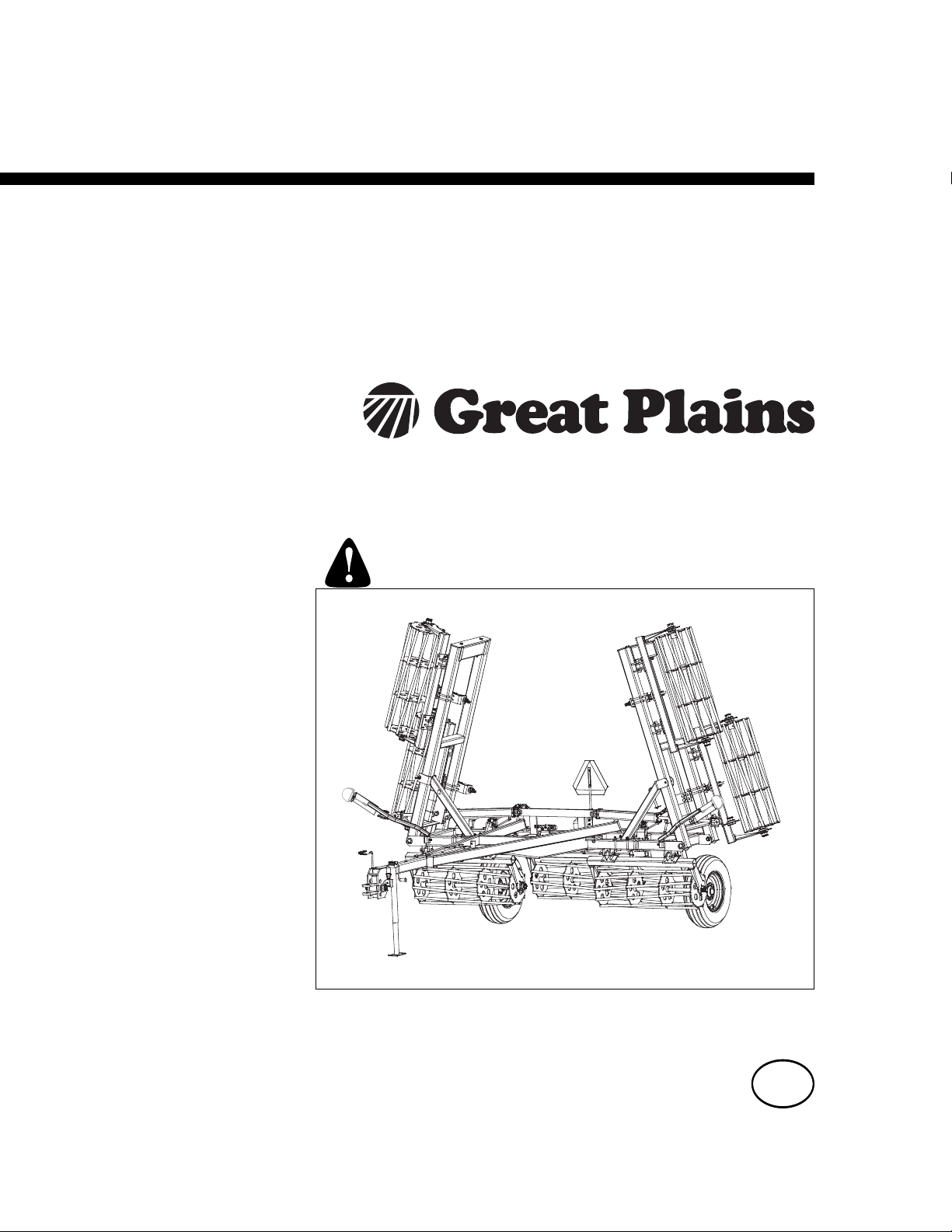
Operator Manual
Series I 2112, 2115, 2317, 2320, 2322,
2325, 2327, 2330, 2332 & 2335
Seedbed Conditioner
Manufacturing, Inc.
www.greatplainsmfg.com
Read the operator’s manual entirely. When you see this symbol, the
subsequent instructions and warnings are serious - follow without
exception. Your life and the lives of others depend on it!
41396
Illustrations may show optional equipment not supplied with standard unit.
ORIGINAL INSTRUCTIONS
© Copyright 2013 Printed 2013-10-08 540-072M
EN
Page 2

Page 3

Great Plains Manufacturing, Inc. iii
Table of Contents
Important Safety Information ...................................... 1
Safety Decals ................................................................. 5
Introduction ...............................................................10
Models Covered ........................................................... 10
Description of Unit ........................................................10
Document Family......................................................10
Using This Manual........................................................10
Definitions................................................................. 10
Owner Assistance ........................................................11
Preparation and Setup ...............................................12
Prior to Going to the Field Checklist.............................12
Spring Pre-load Adjustment......................................12
Hitching Tractor to Seedbed Conditioner ..................... 13
Hydraulic Hose Hookup............................................ 14
Hose Handles...........................................................14
Electrical Hookup......................................................14
Operating Instructions .............................................. 15
Pre-Start Checklist ....................................................... 15
Transporting................................................................. 16
Check Tractor Capacity and Configuration .............. 16
Transport Checklist .................................................. 16
General Operation and In-Field Adjustments............... 16
Hydraulic Down Pressure (S/N 1031HH+)............... 17
Maintenance and Lubrication ................................... 18
Maintenance ................................................................ 18
Lubrication ................................................................... 18
Appendix..................................................................... 20
SC Specifications and Capacities ................................ 20
Tire Inflation Chart ....................................................... 21
Hydraulic Connectors and Torque ............................... 21
Torque Values Chart.................................................... 22
Warranty ...................................................................... 23
Index............................................................................ 25
© Copyright 2006, 2007, 2008, 2009, 2010, 2011, 2012 , 2013 All rights Reserved
Great Plains Manufacturing, Inc. provides this publication “as is” without warranty of any kind, either expressed or implied. While every precaution has been
taken in the preparation of this manual, Great Plains Manufacturing, Inc. assumes no responsibility for errors or omissions. Neither is any liability assumed for
damages resulting from the use of the information contained herein. Great Plains Manufacturing, Inc. reserves the right to revise and improve its products as
it sees fit. This publication describes the state of this product at the time of its publication, and may not reflect the product in the future.
10/08/2013 540-072M
Trademarks of Great Plains Manufacturing, Inc. include: Singulator Plus, Swath Command, Terra-Tine.
Registered Trademarks of Great Plains Manufacturing, Inc. include:
Air-Pro, Clear-Shot, Discovator, Great Plains, Land Pride, MeterCone, Nutri-Pro, Seed-Lok, Solid Stand,
Terra-Guard, Turbo-Chisel, Turbo-Chopper, Turbo Max, Turbo-Till, Ultra-Till, Verti-Till, Whirlfilter, Yield-Pro.
Brand and Product Names that appear and are owned by others are trademarks of their respective owners.
Printed in the United States of America
Page 4

iv 2112-2335SC Great Plains Manufacturing, Inc.
540-072M 10/08/2013
Page 5
Great Plains Manufacturing, Inc. 1
Important Safety Information
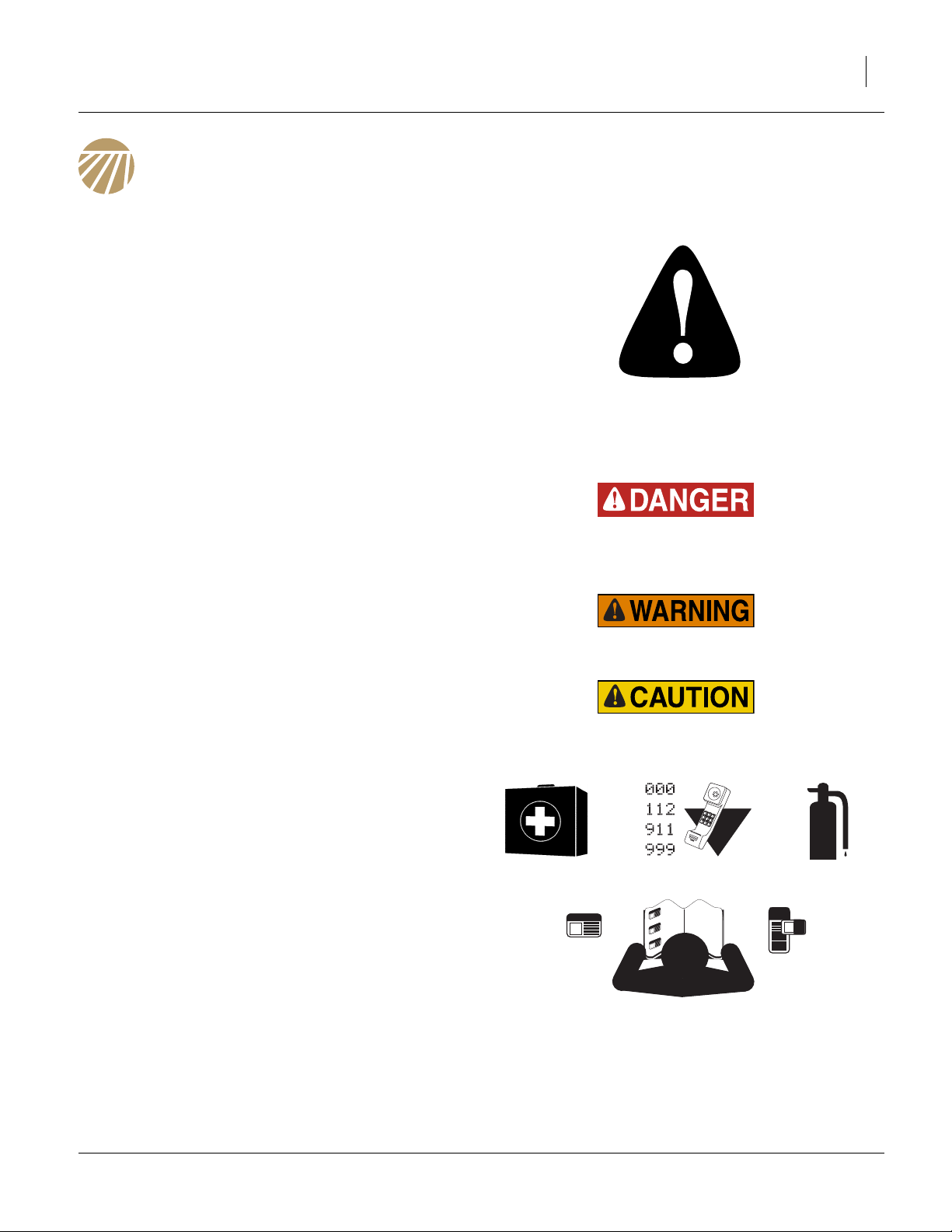
Look for Safety Symbol
The SAFETY ALERT SYMBOL indicates there is a
potential hazard to personal safety involved and extra
safety precaution must be taken. When you see this
symbol, be alert and carefully read the message that follows it. In addition to design and configuration of equipment, hazard control and accident prevention are
dependent upon the awareness, concern, prudence and
proper training of personnel involved in the operation,
transport, maintenance and storage of equipment.
Be Aware of Signal Words
Signal words designate a degree or level of hazard seriousness.
DANGER indicates an imminently hazardous situation
which, if not avoided, will result in death or serious injury.
This signal word is limited to the most extreme situations,
typically for machine components that, for functional purposes, cannot be guarded.
WARNING indicates a potentially hazardous situation
which, if not avoided, could result in death or serious
injury, and includes hazards that are exposed when
guards are removed. It may also be used to alert against
unsafe practices.
CAUTION indicates a potentially hazardous situation
which, if not avoided, may result in minor or moderate
injury. It may also be used to alert against unsafe practices.
Prepare for Emergencies
▲ Be prepared if a fire starts
▲ Keep a first aid kit and fire extinguisher handy.
▲ Keep emergency numbers for doctor, ambulance, hospital
and fire department near phone.
Be Familiar with Safety Decals
▲ Read and understand “Safety Decals” on page 5, thor-
oughly.
▲ Read all instructions noted on the decals.
▲ Keep decals clean. Replace damaged, faded and illegible
decals.
10/08/2013 540-072M
Page 6

2 2112-2335SC Great Plains Manufacturing, Inc.
Wear Protective Equipment
▲ Wear protective clothing and equipment.
▲ Wear clothing and equipment appropriate for the job. Avoid
loose-fitting clothing.
▲ Because prolonged exposure to loud noise can cause hear-
ing impairment or hearing loss, wear suitable hearing protection such as earmuffs or earplugs.
▲ Because operating equipment safely requires your full
attention, avoid wearing entertainment headphones while
operating machinery.
Handle Chemicals Properly
Agricultural chemicals can be dangerous. Improper use
can seriously injure persons, animals, plants, soil and
property.
▲ Read and follow chemical manufacturer’s instructions.
▲ Wear protective clothing.
▲ Handle all chemicals with care.
▲ Avoid inhaling smoke from any type of chemical fire.
▲ Store or dispose of unused chemicals as specified by chemi-
cal manufacturer.
Avoid High Pressure Fluids
Escaping fluid under pressure can penetrate the skin,
causing serious injury.
▲ Avoid the hazard by relieving pressure before disconnecting
hydraulic lines.
▲ Use a piece of paper or cardboard, NOT BODY PARTS, to
check for suspected leaks.
▲ Wear protective gloves and safety glasses or goggles when
working with hydraulic systems.
▲ If an accident occurs, seek immediate medical assistance
from a physician familiar with this type of injury.
Use Safety Lights and Devices
Slow-moving tractors and towed implements can create
a hazard when driven on public roads. They are difficult
to see, especially at night.
▲ Use flashing warning lights and turn signals whenever driv-
ing on public roads.
▲ Use lights and devices provided with implement
540-072M 10/08/2013
Page 7
Great Plains Manufacturing, Inc. Important Safety Information 3
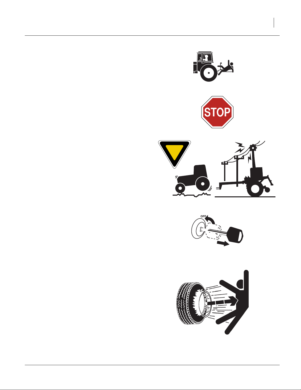
Keep Riders Off Machinery
Riders obstruct the operator’s view. Riders could be
struck by foreign objects or thrown from the machine.
▲ Never allow children to operate equipment.
▲ Keep all bystanders away from machine during operation.
Transport Machinery Safely
Maximum transport speed for implement is 20 mph (32
kph), 13 mph (22 kph) in turns. Some rough terrains
require a slower speed. Sudden braking can cause a
towed load to swerve and upset.
▲ Do not exceed 20 mph. Never travel at a speed which does
not allow adequate control of steering and stopping. Reduce
speed if towed load is not equipped with brakes.
▲ Comply with state and local laws.
▲ Do not tow an implement that, when fully loaded, weighs
more than 1.5 times the weight of towing vehicle.
▲ Carry reflectors or flags to mark Seedbed Conditioner in
case of breakdown on the road.
▲ Keep clear of overhead power lines and other obstructions
when transporting. Refer to transport dimensions under
“SC Specifications and Capacities” on page 20.
▲ Do not fold or unfold the Seedbed Conditioner while the
tractor is moving
Shutdown and Storage
▲ Lower Seedbed Conditioner, put tractor in park, turn off
engine, and remove the key.
▲ Secure Seedbed Conditioner using blocks and supports pro-
vided.
▲ Detach and store machine in an area where children nor-
mally do not play.
Tire Safety
Tire changing can be dangerous and should be performed by trained personnel using correct tools and
equipment.
▲ When inflating tires, use a clip-on chuck and extension hose
long enough for you to stand to one side–not in front of or
over tire assembly. Use a safety cage if available.
▲ When removing and installing wheels, use wheel-handling
equipment adequate for weight involved.
10/08/2013 540-072M
Page 8
4 2112-2335SC Great Plains Manufacturing, Inc.
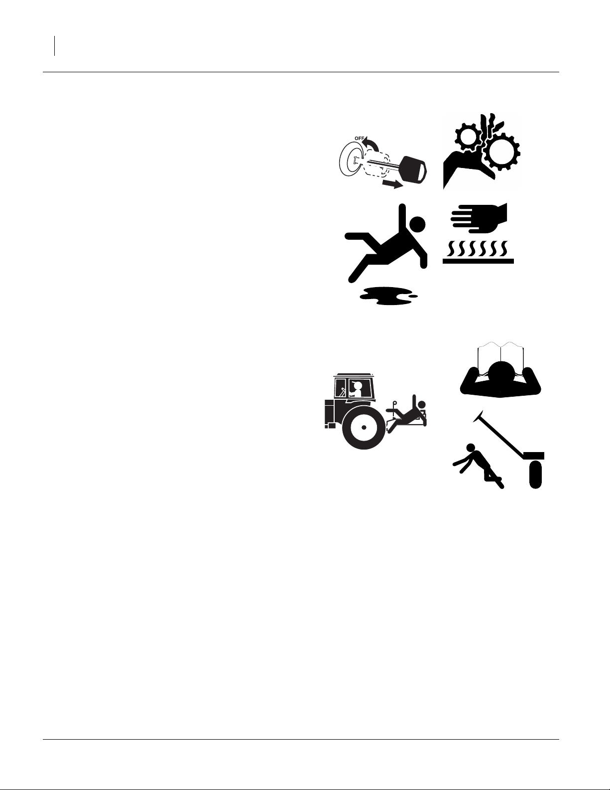
Practice Safe Maintenance
▲ Understand procedure before doing work. Use proper
tools and equipment. Refer to this manual for additional
information.
▲ Work in a clean, dry area.
▲ Lower the machine, put tractor in park, turn off engine,
and remove key before performing maintenance.
▲ Disconnect battery ground cable (-) before servicing or
adjusting electrical systems or before welding on machine.
▲ Inspect all parts. Make sure parts are in good condition
and installed properly.
▲ Remove buildup of grease, oil or debris.
▲ Remove all tools and unused parts from machine before
operation.
Safety At All Times
Thoroughly read and understand the instructions in this
manual before operation. Read all instructions noted on
the safety decals.
▲ Be familiar with all machine functions.
▲ Operate machinery from the driver’s seat only.
▲ Do not leave Seedbed Conditioner unattended with tractor
engine running.
▲ Do not stand between the tractor and machine during hitch-
ing.
▲ Keep hands, feet and clothing away from power-driven
parts.
▲ Wear snug-fitting clothing to avoid entanglement with mov-
ing parts.
▲ Watch out for wires, trees, etc., when folding and raising
machine. Make sure all persons are clear of working area.
540-072M 10/08/2013
Page 9
Great Plains Manufacturing, Inc. Important Safety Information 5
Safety Decals
Safety Reflectors and Decals
Your implement comes equipped with all lights, safety
reflectors and decals in place. They were designed to
help you safely operate your implement.
▲ Read and follow decal directions.
▲ Keep lights in operating condition.
▲ Keep all safety decals clean and legible.
▲ Replace all damaged or missing decals. Order new decals
from your Great Plains dealer. Refer to this section for
proper decal placement.
▲ When ordering new parts or components, also request cor-
responding safety decals.
To install new decals:
1. Clean the area on which the decal is to be placed.
2. Peel backing from decal. Press firmly on surface,
being careful not to cause air bubbles under decal.
818-055C
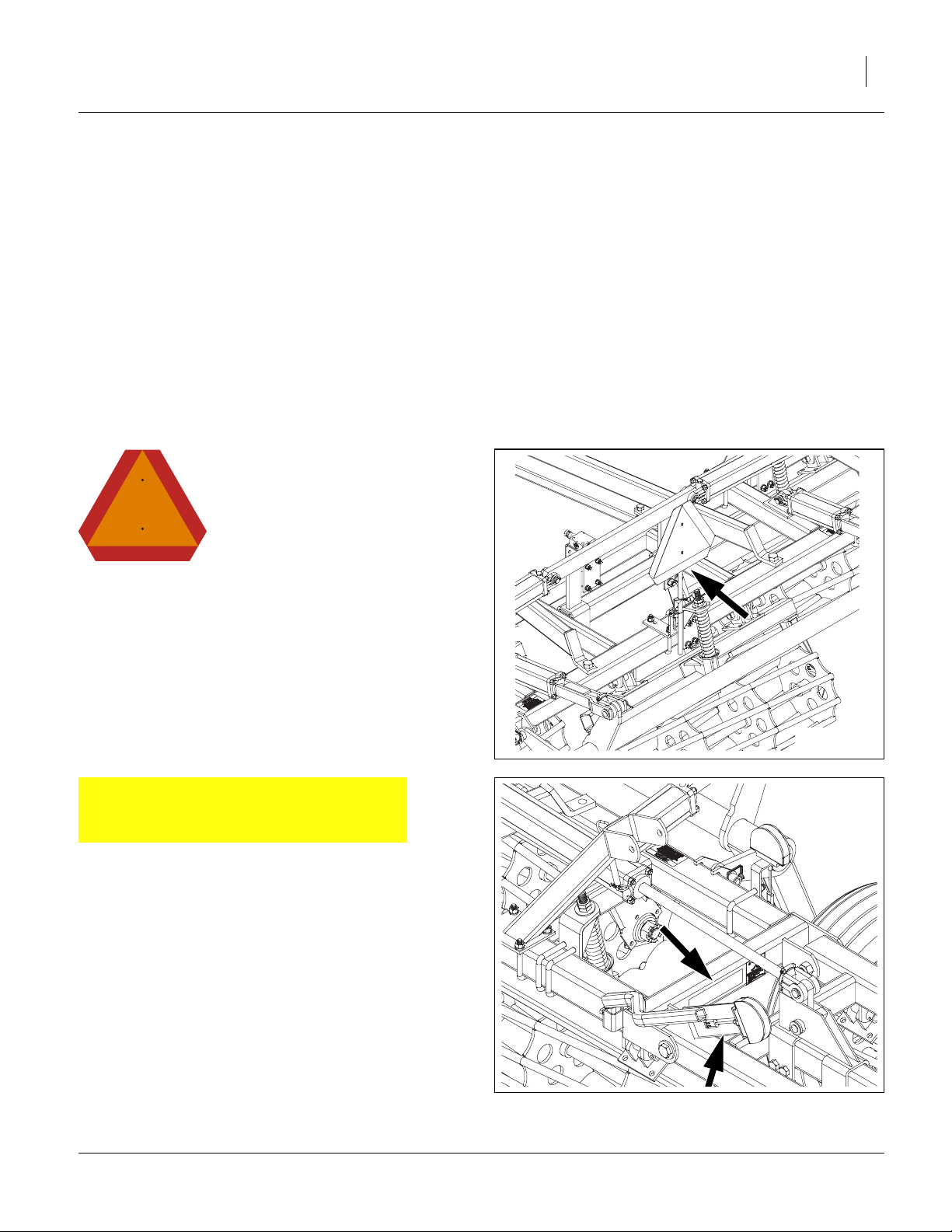
Slow Moving Vehicle Reflector
On the back of the center frame;
1 total
838-615C
Amber Reflectors
One on front of light bracket and one on outside of center
frame (both sides);
4 total
40108
40148
10/08/2013 540-072M
Page 10
6 2112-2335SC Great Plains Manufacturing, Inc.
40152
838-614C
Red Reflectors
On rear of light brackets (top);.
2 total
838-603C
Orange Reflectors
On rear of light brackets (bottom);
2 total
40152
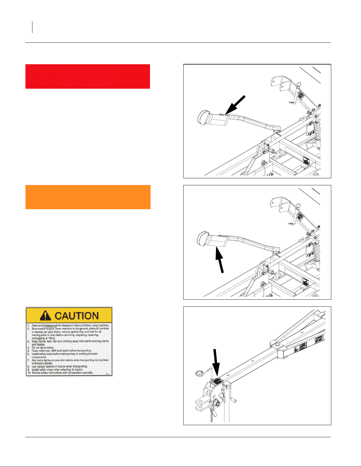
838-598C Caution: Read Operator’s Manual
On front of hitch;
1 total
40149
540-072M 10/08/2013
Page 11

Great Plains Manufacturing, Inc. Important Safety Information 7
838-599C Danger: Electrocution Hazard
Front side of center frame (right);
1 total Models 2317-2335
40150
838-600C Danger: Crushing Hazard
On front of hitch frame (front);
1 total
838-602C Warning: Overhead Wing Hazard
On outside center frame (both sides);
2 total Models 2317-2335
40149
40152
10/08/2013 540-072M
Page 12

8 2112-2335SC Great Plains Manufacturing, Inc.
838-094C Warning: High Pressure Fluid
Front side of center frame (left);
1 total
40150
838-611C Warning: Hand Crushing
On front of hitch frame (rear);
1 total
838-613C Notice: Transport Lock
On outside center of center frame (both sides);
2 total
40149
40108
540-072M 10/08/2013
Page 13

Great Plains Manufacturing, Inc. Important Safety Information 9
838-612C Warning: Wings Could Fall Suddenly
On back of wing stop (both sides);
2 total Models 2317-2335
40152
10/08/2013 540-072M
Page 14

10 2112-2335SC Great Plains Manufacturing, Inc.
Introduction
Great Plains welcomes you to our growing family of new
product owners. The 2112-2335SC have been designed
with care and built by skilled workers using quality materials. Proper setup, maintenance, and safe operating
practices will help you get years of satisfactory use from
the machine. See “SC Specifications and Capacities”
for machine tillage widths.
R
F
U
B
L
D
R
Models Covered
2112SC 1-section
2115SC 1-section
2317SC 3-section
2320SC 3-section
2322SC 3-section
2325SC 3-section
2327SC 3-section
2330SC 3-section
2332SC 3-section
2335SC 3-section
2112SC Seebed Conditioner
L
Figure 1
42290
Description of Unit
The 2112-2335SC is a soil firming and conditioning tool.
Working width ranges from 12 to 35 feet. The implement
is designed to pull behind a host machine, or on its own
to create a firm seedbed for optimum seed germination
while also leveling ridges and breaking clods.
Document Family
540-072Q Pre-Delivery Manual
540-072M Operator Manual (this document)
540-072P Parts Manual
Using This Manual
This manual will familiarize you with
safety, assembly, operation, adjustments, troubleshooting, and maintenance. Read this manual and follow
the recommendations to help
ensure safe and efficient operation.
The information in this manual is current at printing.
Some parts may change to assure top performance.
Definitions
The following terms are used throughout this manual.
A crucial point of information related to the preceding topic.
Read and follow the directions to remain safe, avoid serious
damage to equipment and ensure desired field results.
Note: Useful information related to the preceding topic.
Right-hand and left-hand as used in
this manual are determined by facing
the direction the machine will travel
while in use unless otherwise stated.
An orientation rose in some line art
illustrations shows the directions of:
Up, Back, Left, Down, Front, Right.
R
F
U
B
L
D
540-072M 10/08/2013
Page 15

Great Plains Manufacturing, Inc. Introduction 11
Owner Assistance
If you need customer service or repair parts, contact a
Great Plains dealer. They have trained personnel, repair
parts and equipment specially designed for Great Plains
products.
Refer to Figure 2
Your machine’s parts were specially designed and should
only be replaced with Great Plains parts. Always use the
serial and model number when ordering parts from your
Great Plains dealer. The serial-number plate is located
on the left end of the top front tool bar.
Record your Seedbed Conditioner model and serial number here for quick reference:
Model Number:__________________________
Serial Number: __________________________
Your Great Plains dealer wants you to be satisfied with
your new machine. If you do not understand any part of
this manual or are not satisfied with the service received,
please take the following actions.
1. Discuss the matter with your dealership service manager. Make sure they are aware of any problems so
they can assist you.
2. If you are still unsatisfied, seek out the owner or general manager of the dealership.
Figure 2
Serial Number Plate
41397
For further assistance write to:
Product Support
Great Plains Mfg. Inc., Service Department
PO Box 5060
Salina, KS 67402-5060
(800)255-9215
10/08/2013 540-072M
Page 16

12 2112-2335SC Great Plains Manufacturing, Inc.
Preparation and Setup
This section helps you prepare your tractor and 21122335SC seedbed conditioner for use, and covers tasks
that need to be done seasonally, or when the tractor/
Seedbed Conditioner configuration changes.
Before using the Seedbed Conditioner in the field, you
must hitch it to a suitable tractor, inspect systems and
level the Seedbed Conditioner. Before using the Seedbed
Conditioner for the first time, and periodically thereafter,
certain adjustments and calibrations are required.
Prior to Going to the Field Checklist
Complete this checklist before routine setup:
❑ Read and understand “Important Safety Informa-
tion” on page 1.
❑ Check that all working parts are moving freely, bolts
are tight, and cotter pins are spread.
❑ Make sure your tractor horsepower matches the
implement you are pulling. This is important so the
implement can do the best possible job.
❑ Clean all hydraulic couplings and connect to tractor
as shown on page 13 and 14.
❑ If machine is folded, remove the transport pins from
wing stops. (DO NOT remove pins if the wing is leaning against the pins or putting pressure on the pins.
Use the hydraulics to pull the wings in completely
before unpinning them.) Once the pins are removed,
slowly untold the unit. Make sure no one is under the
wings during the unfolding process.
❑ Check again for hydraulic leaks and watch that
hoses do not get pinched in hinges, wing stops, etc.
❑ After the machine is completely unfolded, raise and
lower the seedbed conditioner several times to purge
air from the hydraulic system. Again check for
hydraulic leaks and tighten or replace if necessary.
❑ Check safety chain hookup. Make sure all warning
lights are hooked up and functioning correctly.
❑ Check that all grease fittings are in place and lubri-
cated. See “Lubrication” on page 18. The hubs will
come pre-greased and will not need greased at this
time.
❑ Check that all safety decals and reflectors are cor-
rectly located and legible. Replace if damaged. See
“Safety Decals” on page 5.
❑ Inflate tires to pressure recommended and tighten
wheel bolts as specified. See “Tire Inflation Chart”
on page 21.
Spring Pre-load Adjustment
Refer to Figure 3
Note: Be sure shipping block is removed from each spring
assembly.
1. Loosen jam nut and set spring pre-load to 8 3/8” by
adjusting nut . Re-tighten jam nut .
2. Put transport locks in place and refold the machine
slowly. Put wing stop pins in place. Always use the transport pins when moving from field to field. You are now
ready to go to the field.
540-072M 10/08/2013
1
2 1
1
Figure 3
Basket Spring Pre-load
2
40846
Page 17

Great Plains Manufacturing, Inc. Preparation and Setup 13
Hitching Tractor to Seedbed Conditioner
Crushing Hazard:
Do not stand or place any body part between Seedbed Conditioner and moving tractor. You may be severely injured or
killed by being crushed between the tractor and Seedbed
Conditioner. Stop tractor engine and set parking brake
before attaching cables and hoses.
To prevent soil compaction on rows, set tractor wheels
between rows. For hillsides and steep slopes, set tractor wheels as wide as possible for maximum stability.
1. Raise tractor three-point arms (if equipped) clear
up to clear Seedbed Conditioner.
2. For TWO-WHEEL DEIVE and MFWD tractors, pin
drawbar in fixed center position for field and transport. For FOUR-WHEEL DRIVE and TRAC-DRIVE
tractors, leave one hole clearance on each side of
drawbar for field position, hitch damage may occur
if pinned solid. Pin in center position for transport to
maintain maximum steering control.
Refer to Figure 4
3. Use jack to raise and lower Seedbed Conditioner
tongue.
4. Back tractor draw bar into alignment with hitch .
5. Secure with locking hitch pin.
6. Secure safety chain to an anchor on the tractor
or pulling implement.
Refer to Figure 5
7. After hitching tractor to Seedbed Conditioner, store
jack on storage tube on top of Seedbed Conditioner hitch frame.
Load Sway Hazard:
Lock drawbar swing to center position to minimize any sideto-side sway to assure proper tracking in the field, and safe
road travel. See “Transporting” on page 16, for safe trans-
porting
1
2
3
4
2
1
3
Figure 4
Jack & Hitch Clevis
42291
4
Figure 5
Jack in Storage
10/08/2013 540-072M
42292
Page 18

14 2112-2335SC Great Plains Manufacturing, Inc.
Hydraulic Hose Hookup
Great Plains hydraulic hoses are color coded to help you
hookup hoses to your tractor outlets. Hoses that go to the
same remote valve are marked with the same color.
Color Hydraulic Function
Yellow Lift & Fold (2 hoses)
Refer to Figure 6
High Pressure Fluid Hazard:
Relieve pressure before disconnecting hydraulic lines. Use
paper or cardboard, NOT BODY PARTS, to check for leaks.
Wear protective gloves and safety glasses or goggles when
working with hydraulic systems. Escaping fluid under pressure
can have sufficient pressure to penetrate the skin causing serious injury. If an accident occurs, seek immediate medical
assistance from a physician familiar with this type of injury.
Only trained personnel should work on system hydraulics.
Hose Handles
To distinguish hoses on the same hydraulic circuit, refer to,
“Hydraulic Hose Hookup” on page 14. The hose under an
extended symbol feeds a cylinder base end. The hose
under a retracted-cylinder symbol feeds a cylinder rod end.
Clean all hydraulic couplings and hook hoses to tractor.
Figure 6
Hose Handles
25463
Electrical Hookup
Refer to Figure 7
Your Seedbed Conditioner is equipped with North American
Lights.
Plug the lighting connector into the tractor outlet.
Test the lights and signalling prior to highway movement.
Figure 7
North American Connector
540-072M 10/08/2013
36051
Page 19

Great Plains Manufacturing, Inc. 15
Operating Instructions
This section covers general operating procedures. Experience, machine familiarity, and the following information
will lead to efficient operation and good working habits.
Always operate farm machinery with safety in mind.
Pre-Start Checklist
Perform the following steps before transporting the Seedbed Conditioner to the field.
❑ Carefully read “Important Safety Information” on
page 1.
❑ Lubricate Seedbed Conditioner as indicated under
“Lubrication” on page 18.
❑ Check all tires for proper inflation.
❑ Check all bolts, pins, and fasteners. Torque as
shown in “Tire Inflation Chart” on page 21.
❑ Check Seedbed Conditioner for worn or damaged
parts. Repair or replace parts before going to the
field.
Check hydraulic hoses, fittings, and cylinders for leaks.
Repair or replace before going to the field.
High Pressure Fluid Hazard:
Relieve pressure and shut down tractor before connecting, disconnecting or checking hydraulic lines. Use a piece of paper
or cardboard, NOT BODY PARTS, to check for leaks. Wear
protective gloves and safety glasses or goggles when working
with hydraulic systems. Escaping fluid under pressure can
have sufficient pressure to penetrate the skin causing serious
injury. If an accident occurs, seek immediate medical assistance from a physician familiar with this type of injury.
10/08/2013 540-072M
Page 20

16 2112-2335SC Great Plains Manufacturing, Inc.
Transporting
See “Hitching Tractor to Seedbed Conditioner” on
page 13 before transporting the Seedbed Conditioner.
Check Tractor Capacity and Configuration
• Know the weight of your Seedbed Conditioner (see
table on speciation page).
• Consult your tractor manual for 3-point limitations.
• Add weights to tractor as required.
When determining the weight of your Seedbed Conditioner, be sure to include the weight of any options.
Transport Checklist
❑ Plan the route. Avoid steep hills. Keep Clearances in
mind.
❑ Make all electrical and hydraulic connections. See
“Hitching Tractor to Seedbed Conditioner” on
page 13.
❑ Raise Seedbed Conditioner.
❑ Be sure all transport locks are installed.
❑ Always have lights on for highway operation.
❑ Comply with all federal, state and local safety laws
when traveling on public roads.
Travel with caution. Allow safe clearance.
Remember that the Seedbed Conditioner is wider than the
tractor.
Loss of Control Hazard:
Use a tractor rated for the load. Add tractor ballast as needed.
Do not exceed 20 mph. Towing the Seedbed Conditioner with a
vehicle that is not adequate, or at high speeds, could lead to
loss of vehicle control. Loss of vehicle can result in a serious
road accident, severe injury or death. Check that your tractor
has enough to handle the weight of the Seedbed Conditioner.
Refer to your tractor’s operator manual for capacities and ballast requirements.
General Operation and In-Field Adjustments
1. Remove the transport pins and unfold machine. Make
sure the fold cylinders are fully extended to allow the
wings to fully flex in the field.
2. If machine has the optional hydraulic down pressure
option, you will need a dedicated closed-center circuit
to the seedbed conditioner. Adjust the tractor flow rate
to the low side and engage the hydraulic lever for constant flow. For seedbed conditioners with Ser#
1001HH-1030HH, adjust the pressure reducing valve
to your conditions with a gauge reading of 600 to
900psi. The higher the pressure the more down pressure on the wing sections. For Serial#1031HH and
higher, See “Hydraulic Down Pressure (S/N
1031HH+)” on page 17 for setup instructions.
3. When turning around on end rows, it is ok to leave the
seedbed conditioner on the ground. The hitch pole
should be extended far enough to prevent the seedbed conditioner from contacting the host machine during turns.
540-072M 10/08/2013
Page 21

Great Plains Manufacturing, Inc. Operating Instructions 17
Hydraulic Down Pressure (S/N 1031HH+)
Refer to Figure 8
Note: Note: This setup procedure is for tractors with
closed-center or pressure compensated flow
hydraulic systems. Open center hydraulics not
supported.
4. Adjust the bypass/pressure reducing valve by turning
knob , Figure1, clockwise all the way in and then
1
backing out 1 full turn.
5. On tractor, adjust flow-control valve to low side of
flow rate.
Note: The faster the flow of oil through the system the
greater potential for oil heating, premature wear or
tractor damage.
6. Lock the fold hydraulic lever for continuous downward oil flow.
7. Adjust bypass/pressure reducing valve knob on
2
implement so the pressure gauge reads 1200 psi.
Never exceed 1400 psi.
8. While watching pressure gauge, slowly open valve
knob until gauge reads 1100 psi. Pressure might
1
rise and then fall off as knob is opened. If pressure
exceeds 1400 psi during this step, the tractor flow is
too high, reduce tractor flow. Lock valve knob at
1
1100 psi.
9. Finally adjust valve to the desired wing down pres-
2
sure setting of 300 to 400 psi. Never exceed 700 psi.
10. In field operation, Lock the fold hydraulic lever for
continuous downward oil flow. If wings are running
too high, increase pressure setting, knob , to level
2
machine. If center is too high, decrease pressure
setting with knob on valve.Never leave tractor
2
valve centered when unfolded with machine in
motion. Machine damage may occur when wings flex
up or down.
Never leave tractor valve centered when unfolded with
machine in motion. Machine damage may occur when wings
flex up or down
2
1
Figure 8
Hydraulic Down Pressure (S/N 1031HH+)
42294
10/08/2013 540-072M
Page 22

18 2112-2335SC Great Plains Manufacturing, Inc.
Maintenance and Lubrication
Maintenance
1. Always use the transport lock when working on or
doing maintenance to the seedbed conditioner. If
folded, be sure your wing stop pins are in place.
Read and understand all safety decals on your
equipment.
2. During the first season of operation check your bolts
for tightness.
3. Replace or rotate worn parts as needed -- hinge
bolts, clevis pins, bearings, etc.
4. Check and tighten or replace any hydraulic leaks.
Check hoses for any leaks. It is important that there
are no leaks on the equipment.
5. Check wheel bearings occasionally for excessive
endplay.
6. Grease wheel bearings sparingly. Over greasing
may cause damage to seals and reduce the life of
the bearing. Grease hinge points periodically. Reel
Bearings are maintanance free & do not require
greasing.
7. If machine is stored outdoors over the winter months,
it is a good idea to fold the machine then set it down
on the ground so all the cylinders are retracted to
protect the cylinder rods. This will extend the life of
the cylinder seals and reduce internal and external
leaks.
By following and maintaining a routine service and lubrication program, your tillage equipment will give you
many years of service.
For the most current manual information, visit Great
Plains website listed below. For more information on
operating, adjusting or maintaining your Great
Plains Discovator, assistance is available. Contact:
Product Support
Great Plains Mfg. Inc., Service Department
PO Box 5060
Salina, KS 67402-5060
(800)255-9215
Lubrication
Multipurpose
spray lube
Wheel Bearing Hub
Multipurpose
grease lube
50
1 zerk on each hub;
2 total
Type of Lubrication: Grease
Quantity: Sparingly, Do Not Over Grease, nay cause damage
seal.
Repack wheel bearings annually or every 2500 acres.
Multipurpose
oil lube
42295
Intervals (service hours)
at which lubrication is
50
required
540-072M 10/08/2013
Page 23

Great Plains Manufacturing, Inc. Maintenance and Lubrication 19
All Hinge Points
10
On all hinge points
Type of Lubrication: Grease
Quantity: Until grease emerges
42296
10/08/2013 540-072M
Page 24

20 2112-2335SC Great Plains Manufacturing, Inc.
Appendix
SC Specifications and Capacities
Model No. 2112SC 2115SC 2317SC 2320SC 2322SC
Tillage Width 12' 11" (363cm)-13' 7" (414cm) 15' 5" (469cm)-16' 1" (489cm) 17' 1" (520cm)-18' 5" (561cm) 19' 7" (596cm)-20' 11" (637cm) 22' 1" (672cm)-23' 5" (713cm)
Center Section 13' 3" (402cm) 15' 9" (480cm) 10' 9" (328cm) 10' 9" (328cm) 10' 9" (328cm)
1st Wing N/A N/A 3' 9" (114cm) 5' 0" (152cm) 6' 3 (191cm)
Transport Width 14' 3" (433cm) 16' 10" (512cm) 15' 0" (457cm) 15' 0" (457cm) 15' 0" (457cm)
Transport Height N/A N/A 7' 11" (241cm) 9' 1" (276cm) 10' 3" (311cm)
Number of Baskets3355 5
Tire Size 9.5 LX15 8 PLY 9.5 LX15 8 PLY 9.5 LX15 8 PLY 9.5 LX15 8 PLY 9.5 LX15 8 PLY
Weight 1701 lbs. (772 kg) 2025 lbs. (919 kg) 2675 lbs. (1213 kg) 3040 lbs. (1379 kg) 3435 lbs. (1558 kg)
Model No. 2325SC 2327SC 2330SC 2332SC 2335SC
Tillage Width 23' 9" (724cm)-25' 9" (785cm) 26' 3" (800cm)-28' 3" (861cm) 28' 9" (876cm)-30' 9" (937cm) 31' 3" (951cm)-33' 3" (1012cm) 33' 9" (1029cm)-35' 9" (1090cm)
Center Section 10' 9" (328cm) 10' 9" (328cm) 10' 9" (328cm) 13' 3" (404cm) 13' 3" (404cm)
1st Wing 7' 3" (221cm) 8' 6" (259cm) 9' 9" (297cm) 9' 9" (297cm) 11' 0" (335cm)
Transport Width 15' 0" (457cm) 15' 0" (457cm) 15' 0" (457cm) 17' 6" (533cm) 17' 6" (533cm)
Transport Height 11' 5" (347cm) 12' 7" (384cm) 13' 9" (419cm) 13' 9" (419cm) 14' 11" (454cm)
Number of Baskets7777 7
Tire Size Center 9.5 LX15 8 PLY 9.5 LX15 8 PLY 9.5 LX15 8 PLY 9.5 LX15 8 PLY 9.5 LX15 8 PLY
Weight 3600 lbs. (1633 kg) 4200 lbs. (1905 kg) 4560 lbs. (2068 kg) 4955 lbs. (2248 kg) 5320 lbs. (2413 kg)
With a continued commitment to constantly improving our products, these specifications are subject to change without
notice.
540-072M 10/08/2013
Page 25

Great Plains Manufacturing, Inc. Appendix 21
Tire Inflation Chart
Tire Inflation Chart
Wheel Tire Size Inflation
Transport/
Center
Transport/
Center
9.5L x 15” 8-Ply
11.5L x 15” 8-Ply
303 kPa
44 psi
248 kPa
36 psi
All tires are warranted by the original manufacturer of the tire.
Tire warranty information is found in the brochures included with
your Operator’s and Parts Manuals or online at the manufacturer’s web sites listed below. For assistance or information, contact your nearest Authorized Farm Tire Retailer.
Manufacturer Web site
Firestone www.firestoneag.com
Gleason www.gleasonwheel.com
Titan www.titan-intl.com
Galaxy www.atgtire.com
BKT www.bkt-tire.com
Hydraulic Connectors and Torque
Refer to Figure 9 (a hypothetical fitting)
Leave any protective caps in place until immediately prior
to making a connection.
1
NPT - National Pipe Thread
Note tapered threads, no cone/flare, and no O-ring.
Apply liquid pipe sealant for hydraulic applications.
Do not use tape sealant, which can clog a filter and/or
plug an orifice.
2
JIC - Joint Industry Conference (SAE J514)
Note straight threads and the 37° cone on
“M” fittings (or 37° flare on “F” fittings).
Use no sealants (tape or liquid) on JIC fittings.
3
ORB - O-Ring Boss (SAE J514)
Note straight threads and elastomer O-Ring .
Prior to installation, to prevent abrasion during tightening, lubricate O-Ring with clean hydraulic fluid.
Use no sealants (tape or liquid) on ORB fittings.
ORB fittings that need orientation, such as the ell
depicted, also have a washer and jam nut
(“adjustable thread port stud”). Back jam nut away
from washer. Thread fitting into receptacle until
O-Ring contacts seat. Unscrew fitting to desired
orientation. Tighten jam nut to torque specification.
4 5
5 7
8 9
5
Dash
Size
-4
-5
-5
-5
-6
-6
-6
-8
-8
-8
Tire Warranty Information
1
9
8
4
2
Figure 9
Hydraulic Connector ID
Fittings Torque Values
Fitting N-m Ft-Lbs
1
⁄4-18 NPT 1.5-3.0 turns past finger
tight
1
⁄2-20 JIC 19-20 14-15
1
⁄2-20 ORB w/jam nut 12-16 9-12
1
⁄2 -20 ORB straight 19-26 14-19
5
⁄16-18 JIC 24-27 18-20
5
⁄16-18 ORB w/jam nut 16-22 12-16
5
⁄16-18 ORB straight 24-33 18-24
3
⁄4 -16 JIC 37-53 27-39
3
⁄4 -16 ORB w/jam nut 27-41 20-30
3
⁄4-16 ORB straight 37-58 27-43
7
5
3
31282
10/08/2013 540-072M
Page 26

22 2112-2335SC Great Plains Manufacturing, Inc.
Torque Values Chart
Bolt
Size
in-tpi
1
⁄4-20
1
⁄4-28
5
⁄16-18
5
⁄16-24
3
⁄8-16
3
⁄8-24
7
⁄16-14
7
⁄16-20
1
⁄2-13
1
⁄2-20
9
⁄16-12
9
⁄16-18
5
⁄8-11
5
⁄8-18
3
⁄4-10
3
⁄4-16
7
⁄8-9
7
⁄8-14
1-8
1-12
1
1
⁄8-7
1
⁄8-12
1
1
⁄4-7
1
1
1
⁄4-12
3
⁄8-6
1
3
1
⁄8-12
1
1
⁄2-6
1
1
⁄2-12
Bolt Head Identification
Grade 2 Grade 5 Grade 8 Class 5.8 Class 8.8 Class 10.9
a
b
d
N-m
ft-lb
7.4 11 16
8.5 13 18
15 24 33
17 26 37
27 42 59
31 47 67
43 67 95
49 75 105
66 105 145
75 115 165
95 150 210
105 165 235
130 205 285
150 230 325
235 360 510
260 405 570
225 585 820
250 640 905
340 875 1230
370 955 1350
480 1080 1750
540 1210 1960
680 1520 2460
750 1680 2730
890 1990 3230
1010 2270 3680
1180 2640 4290
1330 2970 4820
N-m N-m
5.6 8 12
61014 5 811
11 17 25 12 19 27
13 19 27 13 21 29
20 31 44 24 39 53
22 35 49 29 45 62
32 49 70 42 67 93
36 55 78 44 70 97
49 76 105 66 77 105
55 85 120 68 105 150
70 110 155 73 115 160
79 120 170 105 165 230
97 150 210 115 180 245
110 170 240 145 230 300
170 265 375 165 260 355
190 295 420 205 325 450
165 430 605 230 480 665
185 475 670 355 560 780
250 645 910 390 610 845
275 705 995 705 1120 1550
355 795 1290 785 1240 1710
395 890 1440 1270 1950 2700
500 1120 1820 1380 2190 3220
555 1240 2010
655 1470 2380
745 1670 2710
870 1950 3160
980 2190 3560
Bolt Head Identification
Bolt
Size
ft-lb ft-lb ft-lb ft-lb ft-lb
mm x pitch
M 5 X 0.8
M 6 X 1
M 8 X 1.25
M 8 X 1
M10 X 1.5
M10 X 0.75
M12 X 1.75
M12 X 1.5
M12 X 1
M14 X 2
M14 X 1.5
M16 X 2
M16 X 1.5
M18 X 2.5
M18 X 1.5
M20 X 2.5
M20 X 1.5
M24 X 3
M24 X 2
M30 X 3.5
M30 X 2
M36 X 3.5
M36 X 2
a. in-tpi = nominal thread diameter in inches-threads per inch
b. N· m = newton-meters
c. mm x pitch = nominal thread diameter in mm x thread pitch
d. ft-lb = foot pounds
c
5.8 8.8 10.9
N-m N-m N-m
357
71115
17 26 36
18 28 39
33 52 72
39 61 85
58 91 125
60 95 130
90 105 145
92 145 200
99 155 215
145 225 315
155 240 335
195 310 405
220 350 485
280 440 610
310 650 900
480 760 1050
525 830 1150
960 1510 2100
1060 1680 2320
1730 2650 3660
1880 2960 4100
946
Torque tolerance + 0%, -15% of torquing values. Unless otherwise specified use torque values listed above.
25199m
25199
Wheel Bolt Torque Values 1/2”-20 (75-85 ft-lbs) 9/16”-18 (80-90 ft-lbs) 5/8”-18 (85-100 ft-lbs)
540-072M 10/08/2013
Page 27

Great Plains Manufacturing, Inc. Appendix 23
Warranty
Great Plains Manufacturing, Incorporated warrants to the original purchaser that this tillage
and workmanship for a period of one year from the date of original purchase when used as intended and under normal service and conditions
for personal use; 90 days for commercial or rental purposes. This Warranty is limited to the replacement of any defective part by Great Plains
Manufacturing, Incorporated and the installation by the dealer of any
such replacement part. Great Plains reserves the right to inspect any
equipment or part which are claimed to have been defective in material
or workmanship.
This Warranty does not apply to any part or product which in Great
Plains’ judgement shall have been misused or damaged by accident or
lack of normal maintenance or care, or which has been repaired or altered in a way which adversely affects its performance or reliability, or
which has been used for a purpose for which the product is not designed. This Warranty shall not apply if the product is towed at a speed
in excess of 20 miles per hour.
Claims under this Warranty must be made to the dealer which originally
sold the product and all warranty adjustments must by made through
such dealer. Great Plains reserves the right to make changes in materials or design of the product at any time without notice.
This Warranty shall not be interpreted to render Great Plains liable for
damages of any kind, direct, consequential, or contingent, to property.
Furthermore, Great Plains shall not be liable for damages resulting from
any cause beyond its reasonable control. This Warranty does not extend to loss of crops, losses caused by harvest delays or any expense
or loss for labor, supplies, rental machinery or for any other reason.
No other warranty of any kind whatsoever, express or implied, is
made with respect to this sale; and all implied warranties of merchantability and fitness for a particular purpose which exceed
the obligations set forth in this written warranty are hereby disclaimed and excluded from this sale.
This Warranty is not valid unless registered with Great Plains Manufacturing, Incorporated within 10 days from the date of original purchase.
equipment will be free from defects in material
42134
10/08/2013 540-072M
Page 28

24 2112-2335SC Great Plains Manufacturing, Inc.
540-072M 10/08/2013
Page 29

Great Plains Manufacturing, Inc. 25
Index
A
address, Great Plains ............. 11, 18
amber reflectors ................................. 5
B
bearings ........................................... 18
bolts ................................................. 18
C
Caution
Read Operator’s Manual .............. 6
CAUTION, defined ............................. 1
checklists
pre-setup .................................... 12
pre-start ...................................... 15
transport ..................................... 16
chemicals ........................................... 2
children .............................................. 3
clothing ............................................... 2
color code, hose ............................... 14
contact Great Plains ................ 11
covered models ................................ 10
customer service .............................. 11
, 18
D
Danger
Crushing Hazard .......................... 7
DANGER, defined .............................. 1
decal replacement .............................. 5
decals
caution
read manual ........................... 6
danger
crushing .................................. 7
electrocution ........................... 7
notice
transport lock .......................... 8
speed
30km per hr ............................ 9
warning
hand crushing ......................... 8
high pressure fluid .................. 8
overhead wing ........................ 7
wings could fall ....................... 9
decal, safety ....................................... 5
definitions ......................................... 10
directions .......................................... 10
E
email, Great Plains .................. 11, 18
F
fire ...................................................... 1
H
headphones ....................................... 2
hearing ............................................... 2
high pressure fluids ............................ 2
hills ................................................... 13
Hinge Points ..................................... 19
hitching ............................................. 13
hose handles ................................... 14
hydraulic connectors ........................ 21
hydraulic safety .................................. 2
I
inflation ............................................ 21
J
JIC ................................................... 21
Joint Industry Conference ................ 21
J514 ................................................. 21
K
kPa ................................................... 21
L
leaks ..........................................2, 18
left-hand, defined ............................. 10
lights .................................................. 2
lubrication ........................................ 18
M
Maintenance .................................... 18
maintenance safety ............................ 4
medical assistance ........... 2
model number .................................. 11
, 14, 15
N
National Pipe Thread ....................... 21
Note, defined ................................... 10
Notice, defined ................................. 10
NPT ................................................. 21
O
orange reflector ................................. 6
ORB ................................................. 21
orientation rose ................................ 10
O-Ring Boss .................................... 21
owner assistance ............................. 11
P
parts ................................................ 18
phone number, GP .......................... 12
protective equipment ......................... 2
psi .................................................... 21
R
red reflectors ...................................... 6
reflectors
amber ........................................... 5
orange .......................................... 6
red ................................................ 6
SMV ............................................. 5
reflectors, safety ................................ 5
repair parts ...................................... 11
riders .................................................. 3
right-hand, defined ........................... 10
rose, oriention .................................. 10
S
SAE J514 ......................................... 21
safety decal ........................................ 5
safety information .............................. 1
safety symbol ..................................... 1
serial number ...................................11
setup ................................................12
shutdown ............................................ 3
slopes ............................................... 13
SMV (Slow Moving Vehicle) ...............5
Spanish ....................................... 6
Specifications and Capacities .......... 20
speed .................................................7
storage ............................................... 3
storing machine ................................ 18
support .................................... 11
symbol, safety .................................... 1
, 7
, 18
T
tables
document family ......................... 10
fittings torque ..............................21
hose color code ..........................14
models covered ..........................10
torque values ..............................22
tire inflation ....................................... 21
tires ....................................................3
transport ...........................................16
transport lock ....................................18
transport speed .................................. 3
transporting ...................................... 15
U
URLs, tires .......................................21
W
WARNING, defined ............................1
warranty ...................................21
welding ...............................................4
Wheel Bearing Hub ..........................18
www .................................................21
, 23
Numerics
13 mph ............................................... 3
20 mph ...................................... 3
22 kph ................................................3
32 kph ................................................3
540-072M, manual ........................... 10
540-072P ..........................................10
540-072P, manual ............................. 10
540-072Q, manual ...........................10
818-055C, reflector .............................5
838-094C, decal ................................. 8
838-598C, decal ................................. 6
838-599C, decal ................................. 7
838-600C, decal ................................. 7
838-602C, decal ................................. 7
838-603C, reflector .............................6
838-611C, decal ................................. 8
838-612C, decal ................................. 9
838-613C, decal ................................. 8
838-614C, reflector .............................6
838-615C, reflector .............................5
, 16
10/08/2013 540-072M
Page 30

26 2112-2335SC Great Plains Manufacturing, Inc.
540-072M 10/08/2013
Page 31

Page 32

Great Plains Manufacturing, Inc.
Corporate Office: P.O. Box 5060
Salina, Kansas 67402-5060 USA
 Loading...