

Page 1
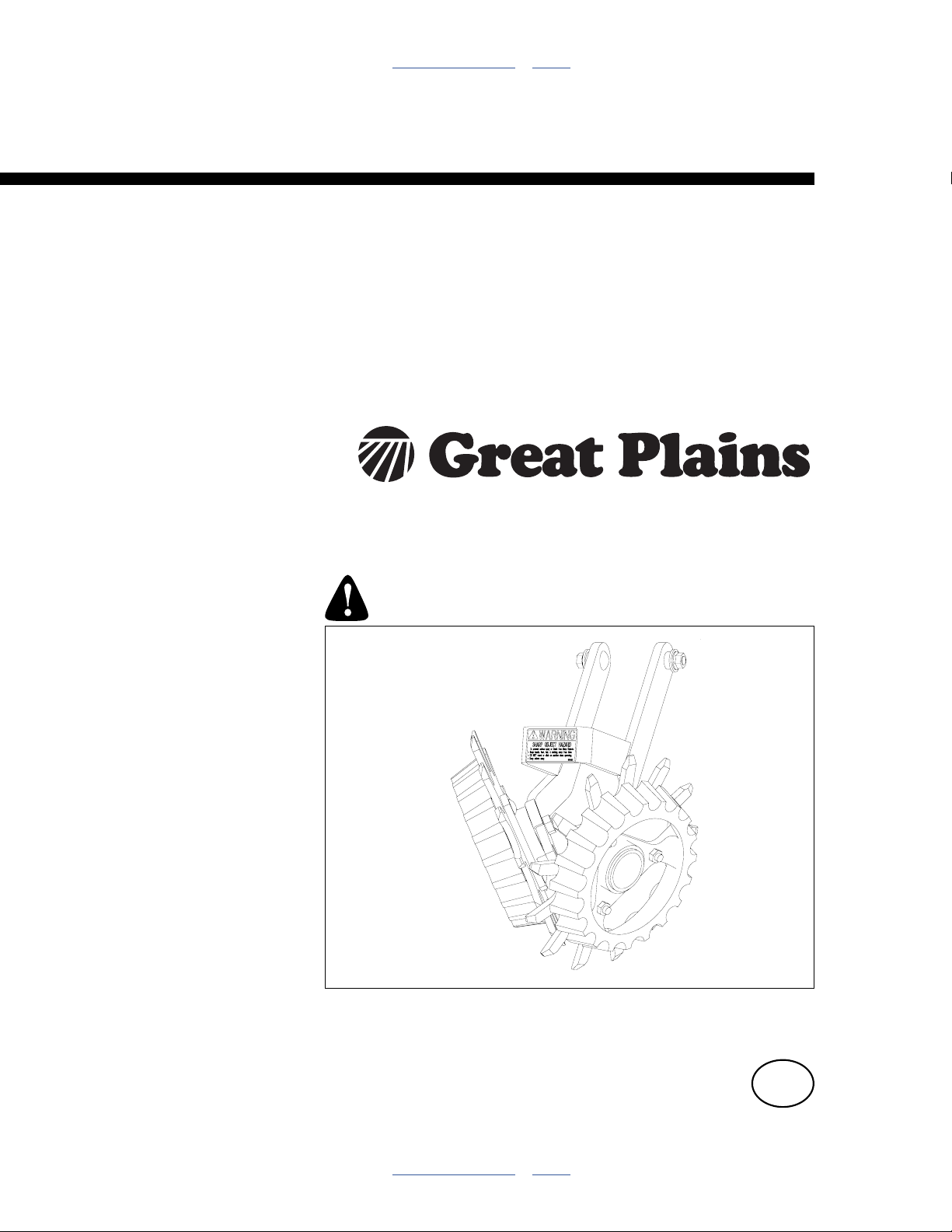
Table of Contents Index
Installation, Operation and
Parts Manual
207-092S, 207-093S, 207-098S
207-213K, 207-215K, 207-216K
2008+ Unit-Mount Row Cleaners
and 207-221A Field Update Kit
Manufacturing, Inc.
www.greatplainsmfg.com
Read the operator manual entirely. When you see this symbol, the
subsequent instructions and warnings are serious - follow without
exception. Your life and the lives of others depend on it!
22816
Illustrations may show optional equipment not supplied with standard unit or may
depict row units and/or implements that differ from yours.
ORIGINAL INSTRUCTIONS
© Copyright 2014 Printed 2014-02-12 204-085M-A
Table of Contents Index
EN
Page 2

Table of Contents Index
Table of Contents Index
Page 3

Great Plains Manufacturing, Inc. Cover Index iii
Table of Contents
Important Safety Information .....................................1
Safety Reflectors and Decals .........................................3
Introduction ..................................................................4
Description of Unit ..........................................................4
Intended Usage ..........................................................4
Document Family ...........................................................4
Supporting Implements for UMRC .................................4
Using This Manual..........................................................4
Definitions................................................................... 4
Call-Outs ....................................................................4
Kits Covered by this Manual...........................................5
Individual Row Kits .....................................................5
Owner Assistance ..........................................................5
Assembly Instructions.................................................6
Before You Start.............................................................6
General Assembly Instructions.......................................6
Tools Required ...............................................................6
Where to Start ................................................................6
UMRC Installation or Update..........................................7
207-221A Update Kit - Prepare Site...........................7
Update Kit: Remove Arms ......................................7
Update Kit: Remove Mount ....................................8
Install UMRC Adjuster Parts....................................... 8
Install UMRC Mount Weldment .................................. 9
Install UMRC Cleaner Arm ......................................... 9
Install UMC-RC Cleaner Arms .....................................10
Install Cleaner Wheel Assemblies................................11
Wheel Identification ..................................................11
Wheel Placement .....................................................11
Mount a Left Wheel ..................................................12
Mount a Right Wheel................................................12
Install Down Stop (UMC-RC Only) ........................... 13
Adjustment and Operation ........................................14
Wheel Placement .........................................................14
Dual Wheel Placement.............................................14
Offset Dual Wheel ................................................14
Retracted Dual Wheel .......................................... 14
Intersected Dual Wheel........................................ 14
Single Wheel Placement .......................................... 15
Single Wheel Forward.......................................... 15
Single Wheel Retracted ....................................... 15
Row Cleaner Depth...................................................... 16
Selecting Depth........................................................16
Row Cleaner Lock-Up .......................................... 16
Adjusting UMRC Depth ............................................ 16
Adjusting UMC-RC Depth ........................................ 17
Troubleshooting......................................................... 18
Maintenance and Lubrication ................................... 19
Maintenance ................................................................ 19
Row Cleaner Maintenance....................................... 19
Lubrication ................................................................... 19
Appendix..................................................................... 20
Torque Values.............................................................. 20
Parts Lists .................................................................... 21
207-213K Dual UMRC Kit ........................................ 21
207-215K Single LH UMRC Kit ................................ 22
207-216K Single RH UMRC Kit ............................... 23
207-092S Single LH UMC-RC Kit ............................ 24
207-093S Single RH UMC-RC Kit............................ 25
207-098S Dual UMC-RC Kit .................................... 26
207-149S Down Stop ............................................... 27
207-221A Mount Update Kit.....................................28
207-217S Dual Arm Assembly ................................. 29
207-218S Left Arm Assembly .................................. 30
207-219S Right Arm Assembly ................................ 31
207-142V Right Hand Cleaner Wheel...................... 32
207-143V Left Hand Cleaner Wheel ........................ 33
815-255C Hub Assembly ......................................... 34
815-255C_HUB Row Cleaner Hub .......................... 35
Abbreviations ............................................................... 36
Warranty ...................................................................... 37
Index............................................................................ 39
© Copyright 2007, 2008, 2010, 2012, 2014 All rights Reserved
Great Plains Manufacturing, Inc. provides this publication “as is” without warranty of any kind, either expressed or implied. While every precaution has been
taken in the preparation of this manual, Great Plains Manufacturing, Inc. assumes no responsibility for errors or omissions. Neither is any liability assumed for
damages resulting from the use of the information contained herein. Great Plains Manufacturing, Inc. reserves the right to revise and improve its products as
it sees fit. This publication describes the state of this product at the time of its publication, and may not reflect the product in the future.
2014-02-12 Cover Index 204-085M-A
Trademarks of Great Plains Manufacturing, Inc. include: Singulator Plus, Swath Command, Terra-Tine.
Registered Trademarks of Great Plains Manufacturing, Inc. include:
Air-Pro, Clear-Shot, Discovator, Great Plains, Land Pride, MeterCone, Nutri-Pro, Seed-Lok, Solid Stand,
Terra-Guard, Turbo-Chisel, Turbo-Chopper, Turbo Max, Turbo-Till, Ultra-Till, Ver ti-Till, Whirlfilter, Yield-Pro.
Brand and Product Names that appear and are owned by others are trademarks of their respective owners.
Printed in the United States of America
Page 4

iv UMRC Table of Contents Index Great Plains Manufacturing, Inc.
204-085M-A Table of Contents Index 2014-02-12
Page 5
Great Plains Manufacturing, Inc. Table of Contents Index 1
Important Safety Information
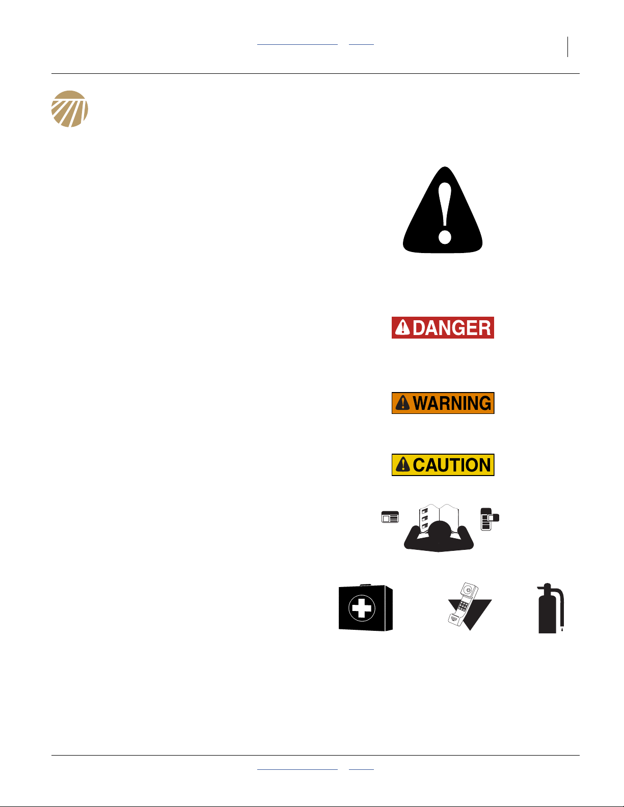
Look for Safety Symbol
The SAFETY ALERT SYMBOL indicates there is a
potential hazard to personal safety involved and extra
safety precaution must be taken. When you see this
symbol, be alert and carefully read the message that
follows it. In addition to design and configuration of
equipment, hazard control and accident prevention are
dependent upon the awareness, concern, prudence and
proper training of personnel involved in the operation,
transport, maintenance and storage of equipment.
Be Aware of Signal Words
Signal words designate a degree or level of hazard
seriousness.
DANGER indicates an imminently hazardous situation
which, if not avoided, will result in death or serious injury.
This signal word is limited to the most extreme situations,
typically for machine components that, for functional
purposes, cannot be guarded.
WARNING indicates a potentially hazardous situation
which, if not avoided, could result in death or serious
injury, and includes hazards that are exposed when
guards are removed. It may also be used to alert against
unsafe practices.
CAUTION indicates a potentially hazardous situation
which, if not avoided, may result in minor or moderate
injury. It may also be used to alert against unsafe
practices.
Be Familiar with Safety Decals
▲ Read and understand “Safety Reflectors and Decals” in
your Operator manual.
▲ Read all instructions noted on the decals.
Prepare for Emergencies
▲ Be prepared if a fire starts.
▲ Keep a first aid kit and fire extinguisher handy.
▲ Keep emergency numbers for doctor, ambulance, hospital
and fire department near phone.
2014-02-12 Table of Contents Index 204-085M-A
000
112
911
999
Page 6
2UMRC Table of Contents Index Great Plains Manufacturing, Inc.
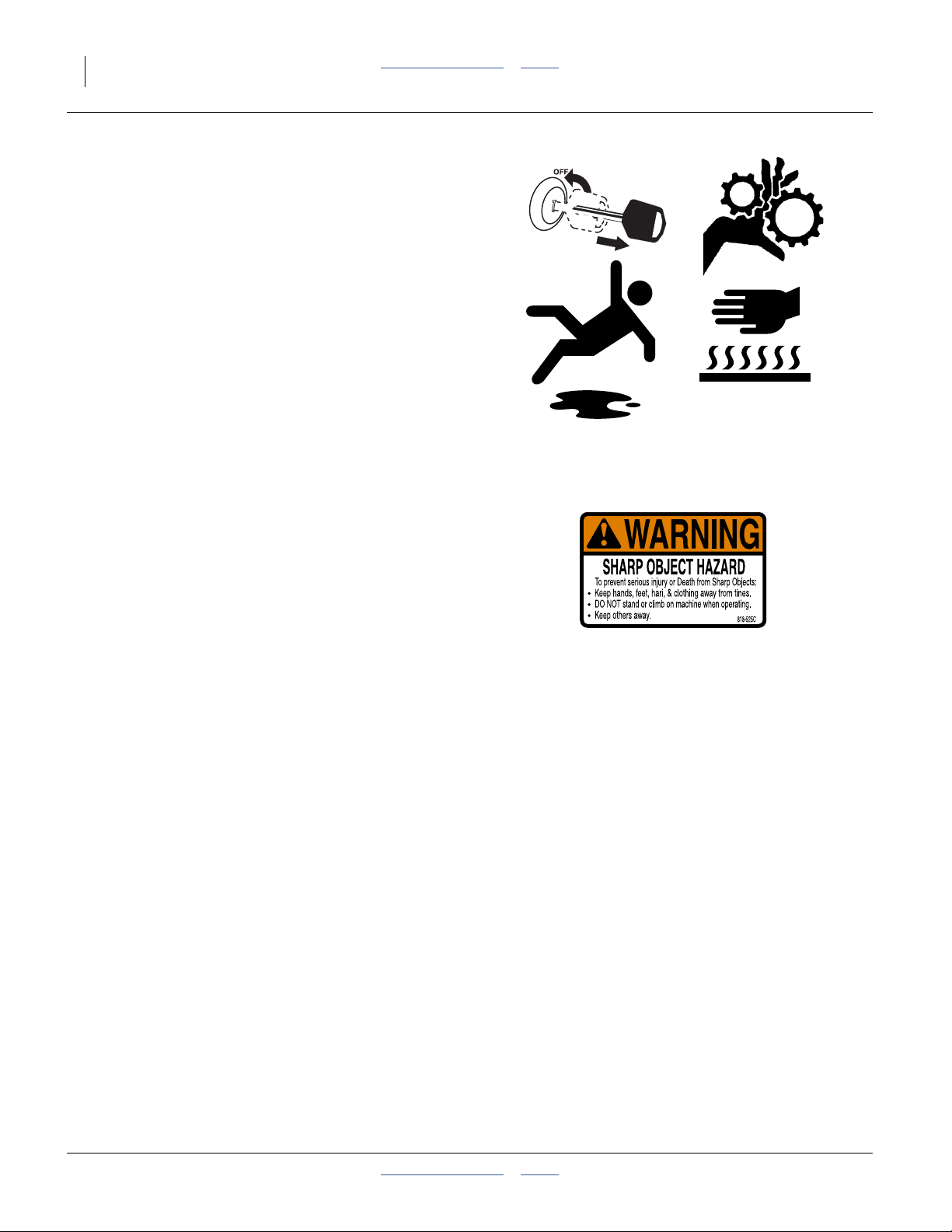
Practice Safe Maintenance
▲ Understand procedure before doing work. Use proper tools
and equipment. Refer to this manual for additional
information.
▲ Work in a clean, dry area.
▲ Wear gloves when handling row cleaner tines.
▲ Make sure all moving parts have stopped and all system
pressure is relieved.
▲ Inspect all parts. Make sure parts are in good condition and
installed properly.
▲ Remove buildup of grease, oil or debris.
▲ Remove all tools and unused parts from implement before
operation.
Safety At All Times
▲ Thoroughly read and understand the instructions in this
manual before operation. Read all instructions noted on the
safety decals.
▲ Be familiar with all implement functions.
▲ Operate machinery from the driver’s seat only.
▲ Do not leave implement unattended with tractor engine
running.
▲ Wear snug-fitting clothing to avoid entanglement with
moving parts.
204-085M-A Table of Contents Index 2014-02-12
Page 7
Great Plains Manufacturing, Inc. Table of Contents Index Important Safety Information 3
Safety Reflectors and Decals
Your row cleaner comes equipped with safety decals in
place. They were designed to help you safely install,
operate and maintain your row cleaner.
▲ Read and follow decal directions.
▲ Keep all safety decals clean and legible.
▲ Replace all damaged or missing decals. Order new decals
from your Great Plains dealer. Refer to this section for
proper decal placement.
▲ When ordering new parts or components, also request
corresponding safety decals.
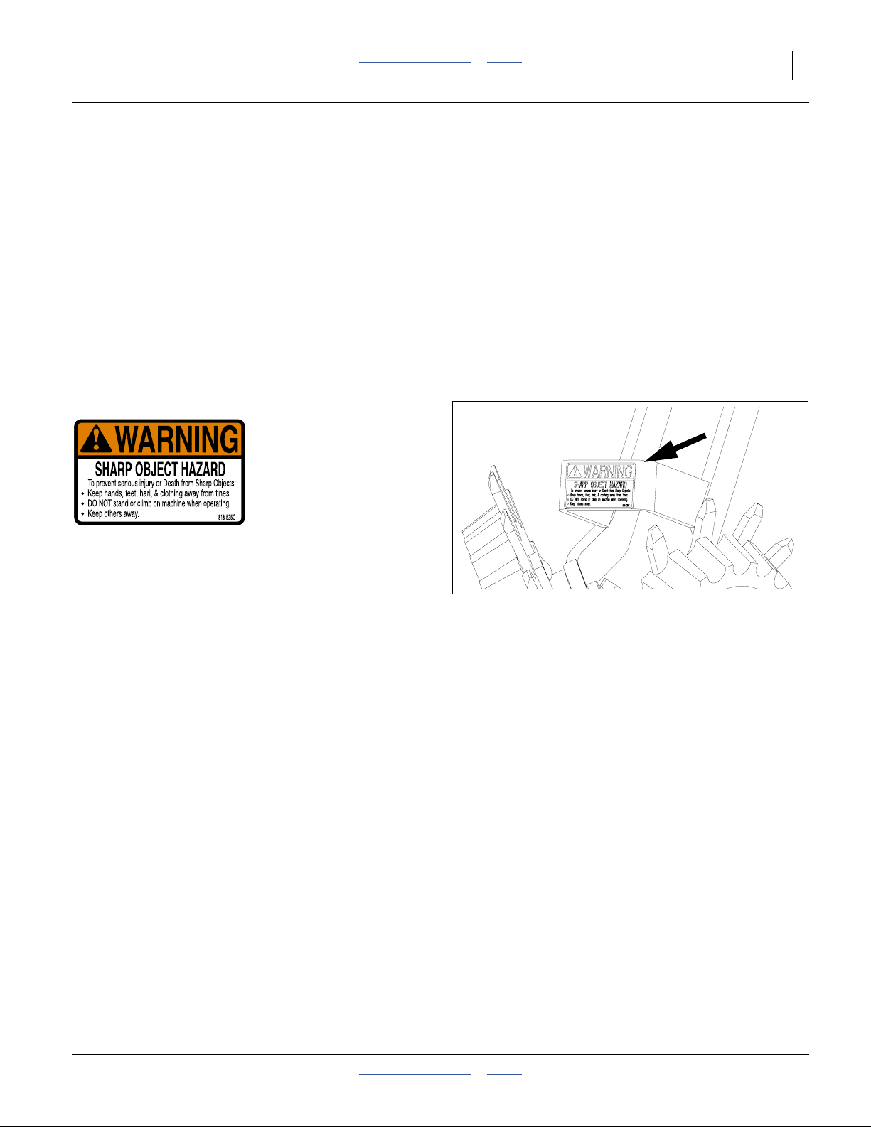
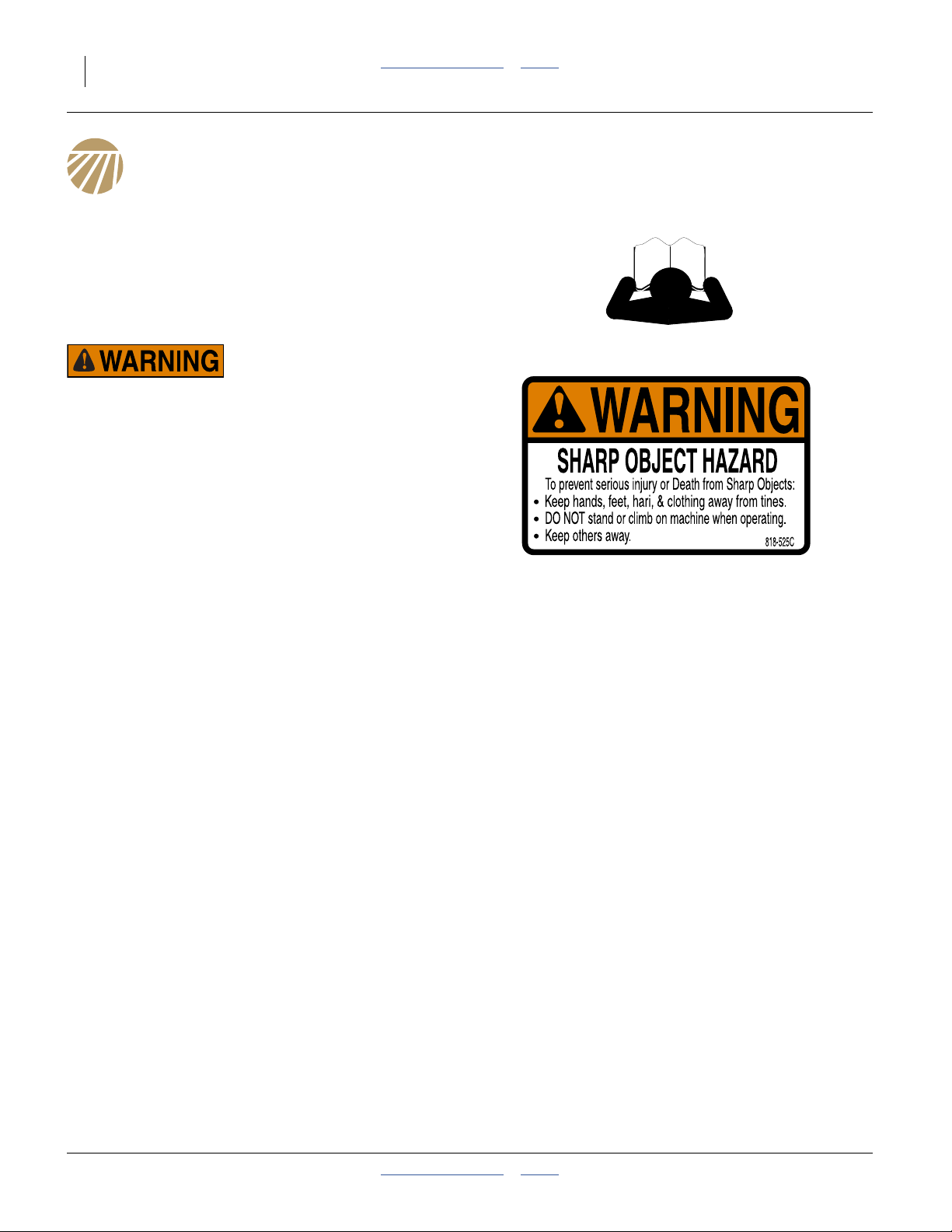
Warning: Sharp Object Hazard
818-525C
top of RC arm gusset;
1 total per RC
To install new decals:
1. Clean the area on which the decal is to be placed.
2. Peel backing from decal. Press firmly on surface,
being careful not to cause air bubbles under decal.
22816
2014-02-12 Table of Contents Index 204-085M-A
Page 8
4UMRC Table of Contents Index Great Plains Manufacturing, Inc.
Introduction
Great Plains welcomes you to its growing family of new
product owners. Your Unit-Mount Row Cleaners (UMRC)
have been designed with care and built by skilled
workers using quality materials. Proper setup,
maintenance, and safe operating practices will help you
get years of satisfactory use from these accessories.
Description of Unit
The row accessories covered by this manual are rigid
toothed wheel row cleaners. They are provided as a
pivoting assembly that attaches to either its own mount
(UMRC) or to a unit-mount coulter (UMC-RC). In either
case, the row cleaner assembly is coupled to the
individual row unit (opener body). It follows the terrain
with the row unit, and raises and lowers with the row unit.
Adjustments are provided for setting the amount of
residue clearing desired.
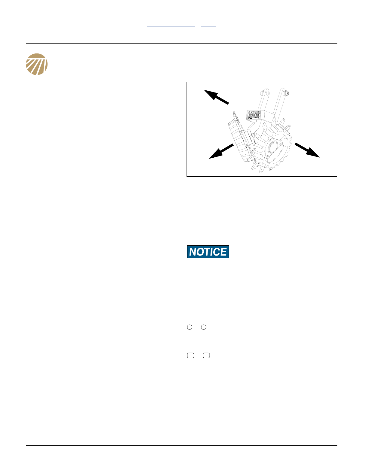
R
Figure 1:
Row Cleaner Arm
L
22816
Intended Usage
Use row cleaners on supporting implements equipped
with Great Plains 25 Series row units or any implements
with unit-mount coulters (UMCs). Use the row cleaners
for residue management with production-agriculture
crops only. Do not modify row cleaner for use with
attachments other than those approved by Great Plains.
Document Family
204-085M-A Installation, Operation and Parts Manual
(this document)
For routine operation and maintenance, you also need to
have your implement Operator and Parts Manuals.
The information in this manual is current at printing.
Some parts may change to assure top performance.
Supporting Implements for UMRC
Tighter row spacings and twin-row spacings do not allow
dual row cleaners. Some implements may only support
UMRC or UMC-RC only.
The row cleaners may not be compatible with other
planters and drills that have 25 Series row units. In
particular, 3-Point 25 Series drills often have insufficient
forward clearance to permit UMRC or UMC-RC use.
Using This Manual
Definitions
The following terms are used throughout this manual.
Right-hand and left-hand as used in this manual are
determined by facing the direction the machine will travel
while in use unless otherwise stated.
Paragraphs in this format present a crucial point of information
related to the current topic. Read and follow the directions to:
- remain safe,
- avoid serious damage to equipment and
- ensure desired field results.
Note: Paragraphs in this format provide useful
information related to the current topic.
Call-Outs
1 9
to
11 64
to
Check with your Great Plains dealer.
Single-digit callouts identify components in
the currently referenced Figure or Figures.
These numbers may be reused for different
items from page to page.
Two-digit callouts reference new parts from
the new parts lists beginning on page 21.
The descriptions match those on the parts,
cartons, bags or item tags, as well as
descriptions your updated Parts Manual.
This manual familiarizes you with safety, assembly,
operation, adjustments, troubleshooting, and
maintenance. Read this manual and follow the
recommendations to help ensure safe and efficient
operation.
204-085M-A Table of Contents Index 2014-02-12
Page 9
Great Plains Manufacturing, Inc. Table of Contents Index Introduction 5
Kits Covered by this Manual
Individual Row Kits
Part
Number
Single Row UMRC Kits
207-213K DOUBLE ROW CLEANER UNIT
207-215K LH ROW CLEANER UNIT
207-216K RH ROW CLEANER UNIT
Individual UMC-RC Row Cleaner Kits
207-092S SINGLE ARM RC ASM LH
207-093S SINGLE ARM RC ASM RH
207-098S DOUBLE ARM RC ASM
UMRC Update Kit
207-221A UMRC MNT WELDMENT FIELD UPDATE
Description
Owner Assistance
If you need customer service or repair parts, contact a
Great Plains dealer. They have trained personnel, repair
parts and equipment specially designed for Great Plains
products.
Your machine’s parts were specially designed and
should only be replaced with Great Plains parts. Always
use the serial and model number when ordering parts
from your Great Plains dealer. The serial-number plate is
located on the front face of the left vertical tube of the
3-point frame.
Record your row cleaner kit model number here for quick
reference:
Model Number:__________________________
Date Purchased: __________________________
Your Great Plains dealer wants you to be satisfied with
your updated machine. If you do not understand any part
of this manual or are not satisfied with the service
received, please take the following actions.
1. Discuss the matter with your dealership service
manager. Make sure they are aware of any problems
so they can assist you.
2. If you are still unsatisfied, seek out the owner or
general manager of the dealership.
For further assistance write to:
Product Support
Great Plains Mfg. Inc., Service Department
PO Box 5060
Salina, KS 67402-5060
785-823-3276
2014-02-12 Table of Contents Index 204-085M-A
Page 10
6UMRC Table of Contents Index Great Plains Manufacturing, Inc.
Assembly Instructions
Before You Start
Most accidents are the result of negligence and
carelessness, usually caused by failure of the operator to
follow simple but necessary safety precautions.
Allow no one to work on or use a row cleaner before
carefully reading this manual.
Sharp Object Hazard:
Row cleaner tines are sharp. The edges of row cleaner wheels
are sharp. UMC blades are sharp. Wear gloves when handling
these parts. Maintain awareness of installed coulters and row
cleaners when working in front of row units.
Perform these steps before installing your row cleaners.
1. Read and understand “Important Safety
Information” starting on page 1.
2. Hitch the implement to a suitable tractor. Refer to the
hitching topic in the Operator Manual.
3. Position the implement in a level, dry, well-lighted
area. Pick a location with a clear surface beneath, so
that any dropped tools or parts can be easily located.
4. Unfold the implement.
5. Raise the row units (or leave them raised).
6. Install any lift locks provided.
Set all hydraulic circuits to neutral.
7. Shut off the tractor. Set the parking brake.
General Assembly Instructions
Start mounting with the left-most row unit of the
implement. Single-arm row cleaners are provisioned as
left and right hand pairs. Start with a left hand row
cleaner, and alternate left-right-left-right across the
implement.
Some fasteners may be loosely assembled. Remove
them before mounting that component. Due to evolving
manufacturing practices, some assemblies may already
be completely pre-assembled. If so, check that fasteners
are tight, and skip the unneeded assembly steps.
Torque values for fasteners are shown on page 20.
Wheel bearings are pre-greased and should not require
additional lubrication until the first service interval.
204-085M-A Table of Contents Index 2014-02-12
Tools Required
• Basic hand tools, including an extension for any socket
or air wrench to be used
• Screw thread adhesive, such as Loctite
Where to Start
UMRC: Unit-Mount Row Cleaner installation
instructions begin on page 7.
UMC-RC: Unit-Mount Coulter Row Cleaner installation
instructions begin on page 10.
Page 11
Great Plains Manufacturing, Inc. Table of Contents Index Assembly Instructions 7
UMRC Installation or Update
For Unit-Mount Row Cleaners (no UMC disk coulters).
Refer to Figure 2 (which depicts dual RC mounting;
mounting of the single-wheel RCs is identical)
Unit-Mount Row Cleaners (UMRCs) are used only on
25 Series row units which either have no accessories
forward of the openers (other than a disk shield ).
1
In the case of plain 25 Series row unit, the UMRC
mounts on the front face of the row unit shank.
2
Note: 25 Series row units with unit-mount coulters use
different models of row cleaner (UMC-RC), for
which the assembly instructions begin on page 10.
207-221A Update Kit - Prepare Site
If installing an all new row cleaner, and not updating an
existing row cleaner, begin at step 1 on page 8.
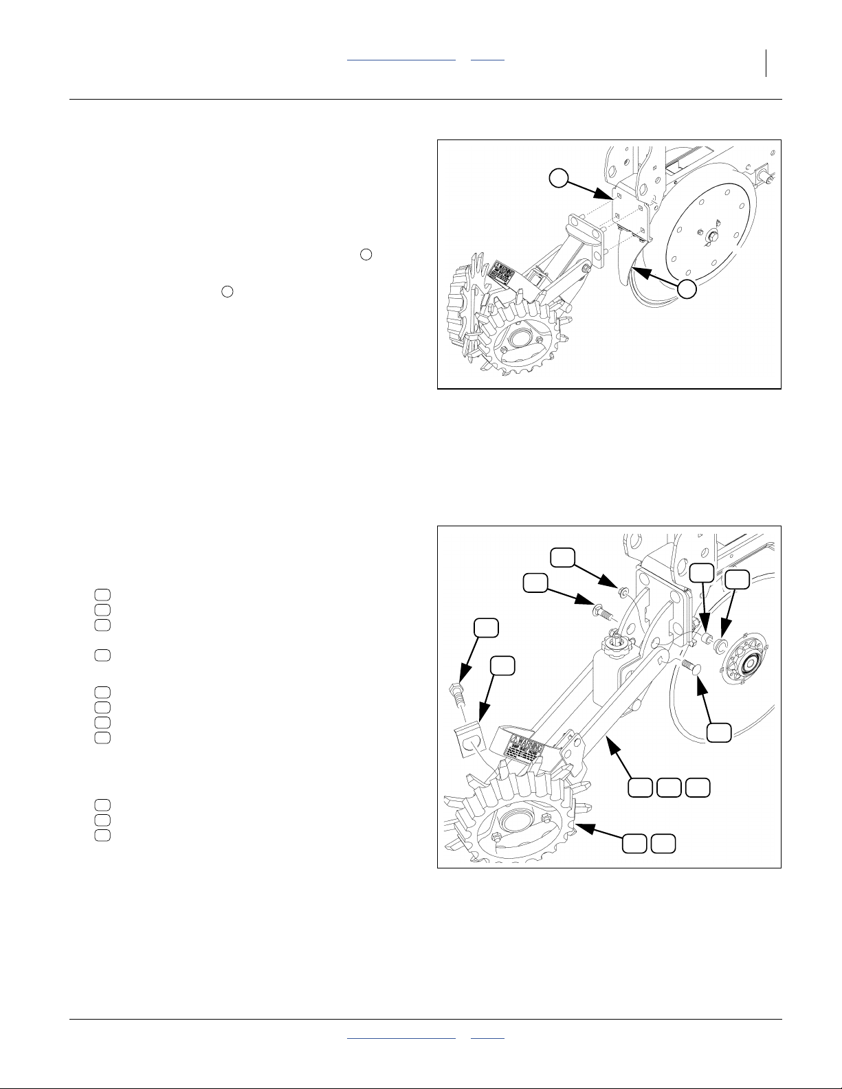
Update Kit: Remove Arms
For safety and convenience, remove the old wheel, then
the old arm, before removing the old mount. Some parts
are re-used.
Refer to Figure 3
A. Remove and save one or both wheels:
51
802-228C HHCS 5/8-11X1 1/2 GR5 NYL
47
828-057C RC HUB LOCK
31
207-143V RIGID ROW CLEANER ASM LH
or
38
207-142V RIGID ROW CLEANER ASM RH
B. Remove two sets of:
29
207-067D UMC RC PIVOT TUBE
33
802-331C RHSNB 1/2-13X1 3/4 GR5
21
803-169C NUT HEX FLG. LOCK 1/2-13 PLT.
36
817-615C RC ARM PIVOT BUSHING
These parts are not re-used. They are replaced by a
single new bolt and nut.
C. Remove and save the arm, which is one of:
30
207-094H SINGLE ARM RC WLD LH (odd rows)
39
207-095H SINGLE ARM RC WLD RH (even rows)
40
207-099H DOUBLE ARM RC WLD
If your left-right arm installation is not standard
(left-most row is a left arm, then alternating
right-to-left), note from which row each arm was
removed.
Note: Wheelsare also handed (left or right). Keep left and
right wheels in separate collection areas.
, and
51
47
2
Figure 2:
UMRC Shank Mounting
21
33
30 39 40
31 38
Figure 3:
Remove Old Arm
1
27310
29
36
33
27348
2014-02-12 Table of Contents Index 204-085M-A
Page 12
8UMRC Table of Contents Index Great Plains Manufacturing, Inc.
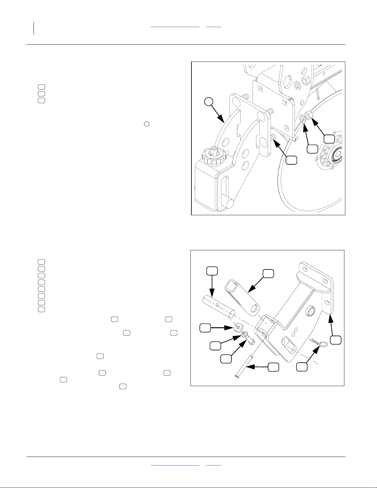
Update Kit: Remove Mount
Refer to Figure 4
D. Remove four sets of:
17
802-106C RHSNB 1/2-13X1 1/2 GR5
23
804-015C WASHER LOCK SPRING 1/2 PLT
20
803-020C NUT HEX 1/2-13 PLT
1
Although identical to new parts in the kit, these
fasteners are not re-used.
E. Remove the old knob-adjust weldment . The
1
weldment, and all parts still installed in it, are not
re-used.
20
23
17
Install UMRC Adjuster Parts
Refer to Figure 5
1. Select one each:
11
207-072D UMRC MOUNT ROUND TUBE
13
207-107D UMRC ADJUSTMENT TUBE
14
207-108D SPACER
15
207-214H UMRC MOUNT WELD
19
802-673C HHCS 7/16-14X1 1/4 GR5 PLT
22
804-014C WASHER LOCK 7/16 PLT
24
805-031C PIN HAIR COTTER .092 WIRE
25
805-385C PIN CLEVIS 3/8 X 3 PLT
2. Insert the adjustment tube in the weldment
with the large holes facing the slots in the weldment.
Hold in place with the clevis pin and cotter pin .
Pin the tube at the highest position that has the large
tube hole fully visible in the slots.
3. Insert the round tube through both the weldment
and the adjustment tube.
4. Place the lock washer and then the spacer on
the bolt . Apply thread adhesive to the threads,
19
and secure bolt in round tube .
13 15
25 24
11
22 14
11
14
11
22
Figure 4:
Remove Old Mount
19
Figure 5:
UMRC Adjuster Parts
13
25
27349
15
24
27318
204-085M-A Table of Contents Index 2014-02-12
Page 13
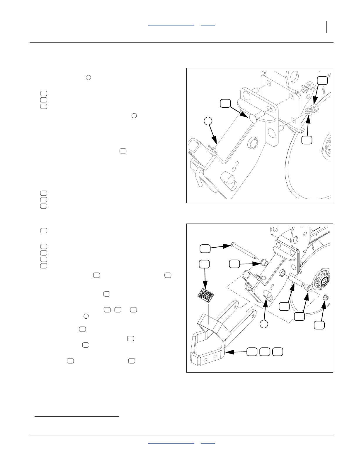
Great Plains Manufacturing, Inc. Table of Contents Index Assembly Instructions 9
Install UMRC Mount Weldment
Refer to Figure 6 (which depicts a shank mounting)
5. Select the mount partially assembled above.
1
20
6. Select four sets of:
17
802-106C RHSNB 1/2-13X1 1/2 GR5
23
804-015C WASHER LOCK SPRING 1/2 PLT
20
803-020C NUT HEX 1/2-13 PLT
7. Attach the UMRC mount weldment to the row unit
1
shank face using the four sets of fasteners. Loosely
17
1
tighten fasteners, as the alignment of the complete
unit may require adjustment before final tightening.
Note: Depending on tools available, it may be more
convenient to insert the bolt from behind row
17
23
face, and install the lock washers and nuts in front.
Install UMRC Cleaner Arm
Refer to Figure 7 (which depicts a dual RC arm)
8. Select one of the following, depending on kits:
30
207-094H SINGLE ARM RC WLD LH (odd rows)
39
207-095H SINGLE ARM RC WLD RH (even rows)
40
207-099H DOUBLE ARM RC WLD
Figure 6:
UMRC Weldment Mounting
27314
9. Select two:
26
817-084C PARALLEL ARM PIVOT BUSHING
10. Select one each:
12
207-106D ROW CLEANER PIVOT PIPE
37
818-525C DECAL SHARP OBJECT WARNING
18
802-046C HHCS 1/2-13X5 1/2 GR5
20
803-020C NUT HEX 1/2-13 PLT
11. Insert the pivot pipe in one end of a bushing .
12 26
12. Insert these in the pivot holea, as shown in the figure.
13. Place the other bushing on the other end of the
26
tube.
14. With the arm weldment ( , or ) above the
adjustment tube , align the end holes of the arm
2
30 39 40
with the bushing assembly, and temporarily hold in
place with bolt .
15. Apply thread adhesive to the bolt .
Secure with nut .
18
18
20
16. Clean and dry the surface of the gusset on the arm
weldment and apply the decal .
40 37
17. Repeat UMRC step 1 through step 16 for all rows.
Skip to “Install Cleaner Wheel Assemblies” on
page 11.
18
37
26
2
30
39 40
Figure 7:
UMRC Arm Mounting
12
26
20
27315
a. 2013 and earlier weldments may have two pivot holes. Only the upper hole is used.
2014-02-12 Table of Contents Index 204-085M-A
Page 14
10 UMRC Table of Contents Index Great Plains Manufacturing, Inc.
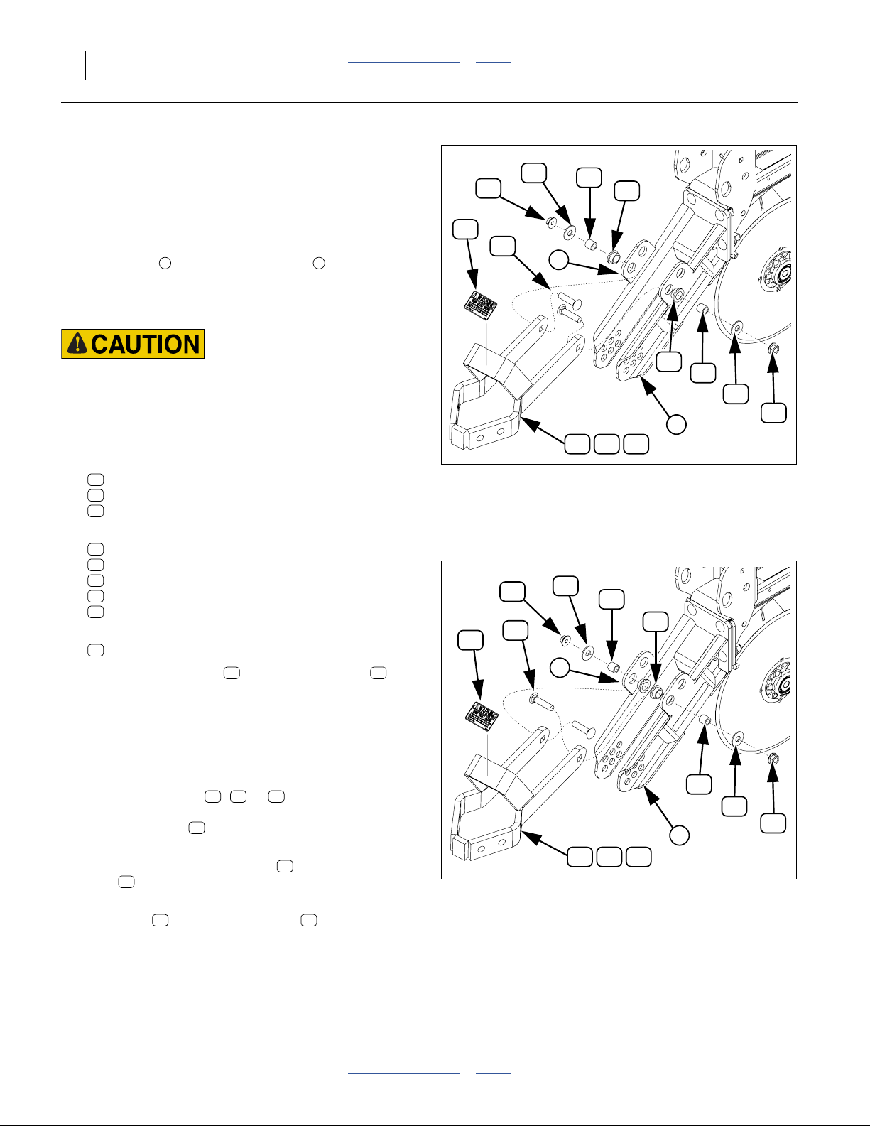
Install UMC-RC Cleaner Arms
For Unit-Mount Coulter - Row Cleaners (disk coulters
present).
Refer to Figure 8 or Figure 9
(which depicts a shank mounted UMC and a dual RC arm).
UMC-RC kits do not include a mount weldment, as they
rely on mounts on the UMC brackets . If the UMCs
are not yet on the implement, install them before
installing the row cleaners, but do not install the coulter
blades until step 9 below.
Sharp Object Hazards:
If the UMC blades are already installed, exercise extra care
while installing the row cleaners.
The UMC itself is mounted directly on the row unit shank.
Refer to Figure 7 (which depicts a shank mounting)
1. Select one of the following, depending on kits:
30
207-094H SINGLE ARM RC WLD LH (odd rows)
39
207-095H SINGLE ARM RC WLD RH (even rows)
40
207-099H DOUBLE ARM RC WLD
2. Select two each:
29
207-067D UMC RC PIVOT TUBE
33
802-331C RHSNB 1/2-13X1 3/4 GR5
21
803-169C NUT HEX FLG. LOCK 1/2-13 PLT.
34
804-017C WASHER FLAT 1/2 USS PLT
36
817-615C RC ARM PIVOT BUSHING
3. Select one:
37
818-525C DECAL SHARP OBJECT WARNING
4. Insert the pivot tubes inside the bushings .
Insert these two assemblies in the UMC mount
holes, from the outside (preferred placement,
Figure 8). If clearance difficulties are encountered,
use the alternate placement in Figure 9.
5. Insert these in the lower/forward holes (for a 15 inch
coulter blade, upper/rear holes for a 14 inch blade).
6. Align the RC arm ( , or ) in between the
holes with the new bushing assemblies, and hold in
place with bolts .
7. Snug square shanks of bolts in arm holes, and
secure bolts with flat washers and flanged lock
nuts .
8. Clean and dry the surface of the gusset on the arm
weldment and apply the decal .
9. If a coulter is also being installed, mount the blade.
10. Repeat UMC-RC step 1 through step 8 for all rows.
1 2
29 36
30 39 40
33
34
21
40 37
37
37
21
34
29
36
33
1
30 39 40
Figure 8:
UMC-RC Arm Mounting
Preferred Bushing Placement
21
34
29
33
1
30 39 40
Figure 9:
UMC-RC Arm Mounting
Alternate Bushing Placement
36
36
29
34
21
2
27316
29
34
21
2
27491
204-085M-A Table of Contents Index 2014-02-12
Page 15

Great Plains Manufacturing, Inc. Table of Contents Index Assembly Instructions 11
Install Cleaner Wheel Assemblies
Wheel Identification
Refer to Figure 10 (which depicts a Left wheel )
Row cleaner wheels are pre-assembled. Each assembly
is intended for either Left or a Right mounting.
38
207-142V RIGID ROW CLEANER ASM RH
31
207-143V RIGID ROW CLEANER ASM LH
If any identifying tags or packaging are separated from a
wheel, you can identify the wheel type by a part number
stamped in spoked wheel face. Left and Right wheels
have part numbers ending in “L” and “R”, respectively.
The first wheel to be mounted is a Left wheel. Whether
single- or dual-arm, the next wheel is a Right, and they
alternate Left-Right across the implement.
Field Results Risk:
Be sure to mount Left wheels on Left arms or on the left side of
dual arms, and vice-versa for Right. Unsatisfactory row
cleaning and premature cleaner wear may otherwise result.
31
Figure 10:
Wheel Identification
27317
Wheel Placement
Refer to Figure 11 (which depicts a Left single-arm RC)
Each arm (and each side of a dual arm) has two
mounting holes for cleaner wheels. Which hole(s) to use
is dependent on your field conditions and field
experience.
Review the topic “Wheel Placement” on page 14, and
make a determination as to which hole(s) to use for the
initial mounting. If no clear choice emerges, use the
forward holes.
Figure 11:
27319
Wheel Placement Choice
2014-02-12 Table of Contents Index 204-085M-A
Page 16

12 UMRC Table of Contents Index Great Plains Manufacturing, Inc.
Mount a Left Wheel
Refer to Figure 12 (which depicts mounting the wheel
assembly in the aft arm hole of a single arm; left side
51
dual-wheel mounting is identical)
11. Select one:
31
207-143V RIGID ROW CLEANER ASM LH
12. Partially disassemble it (some parts may be attached
by cable ties), freeing the:
47
828-057C RC HUB LOCK
51
802-228C HHCS 5/8-11X1 1/2 GR5 NYL
13. Insert the bolt through the selected arm hole from
inside the arm . If a
52
804-195C WASHER FLAT 1.31ODX.65IDX.188T
51
1
is present, it is not used.
14. Place the hub lock over the bolt threads from
47
47
1
2
outside the arm, with the bent edge of the lock up
and toward the inside of the arm. This lock prevents
the back face of the hub from rotating while you
secure the bolt in the next step.
15. Place the cleaner wheel assembly on the bolt,
2
and screw the bolt into the wheel hub. Use the lock,
up against the hub, to prevent hub rotation. Torque
bolt to specifications once hub and lock are fully
seated.
Figure 12:
Left RC Wheel Install
27320
Mount a Right Wheel
Refer to Figure 13 (which depicts mounting the wheel
assembly in the aft arm hole of a single arm; right-side dual
mounting is identical)
16. Select one:
38
207-142V RIGID ROW CLEANER ASM RH
17. Partially disassemble it (some parts may be attached
by cable ties), freeing the:
47
828-057C RC HUB LOCK
51
802-228C HHCS 5/8-11X1 1/2 GR5 NYL
18. Insert the bolt through the selected arm hole from
inside the arm . If a
52
804-195C WASHER FLAT 1.31ODX.65IDX.188T
51
1
is present, it is not used.
19. Place the hub lock over the bolt threads from
47
outside the arm, with the bent edge of the lock up
and toward the inside of the arm. This lock prevents
the back face of the hub from rotating while you
secure the bolt in the next step.
20. Place the cleaner wheel assembly on the bolt,
2
and screw the bolt into the wheel hub. Use the lock,
up against the hub, to prevent hub rotation. Torque
bolt to specifications once hub and lock are fully
seated.
3
Figure 13:
Right RC Wheel Install
51
47
4
27320
204-085M-A Table of Contents Index 2014-02-12
Page 17

Great Plains Manufacturing, Inc. Table of Contents Index Assembly Instructions 13
Install Down Stop (UMC-RC Only)
If you have installed UMRCs, the adjuster hardware is
already installed. Skip this section and make final
adjustments per the instructions in the next section.
The height adjustment for UMC-RC units is a sliding
stop.
21. Select one:
41
207-148H UM ROW CLEAN DOWN STOP WLDM
22. Set two sets of:
42
802-270C RHSNB 5/16-18X1 1/2 GR5
43
803-008C NUT HEX 5/16-18 PLT
44
804-009C WASHER LOCK SPRING 5/16 PLT
45
804-036C WASHER FLAT 5/16 SAE PLT
Note: On single-wheel arms, the down stop mounts on
the side of the arm with the wheel. On dual-wheel
arms, the down stop may be mounted on either
side, and you may want to select the location on a
per-row basis, for ease of access for adjustments.
23. Swing the cleaner arm up until the tines are well
above the height of the bottom edge of the row unit
opener disks. Support the arms at this height.
24. From underneath the arm , orient the tip end of the
down-stop forward (longer bolt slot aft), and slide
41
1
the down stop up onto the arm. Temporarily secure
with one or two bolts .
42
42
41
45
Figure 14:
Right RC Down-Stop
44
1
43
27321
Insert the bolts from the inside of the arm. Placing
the threads outside the arm minimizes collection of
residue during operations.
25. Place a flat washer , and then a lock washer
onto each bolt, and loosely add a nut .
45 44
43
26. If you know the initial height at which you desire to
operate the cleaner (from the next section), set the
cleaner arm at that height and support it there.
27. Slide the adjuster back until it contacts the coulter
bracket. Secure the nuts. Remove the support
holding up the arm.
2014-02-12 Table of Contents Index 204-085M-A
Page 18

14 UMRC Table of Contents Index Great Plains Manufacturing, Inc.
Adjustment and Operation
Wheel Placement
Cleaner arms have two alternate mounting holes for
cleaner wheels. Which hole to use depends on your field
conditions, experience and preference. Great Plains
suggests starting with the “more aggressive” positions.
Too aggressive row cleaner use can remove treated soil
from the seed furrow area, reducing effectiveness of
treatments.
Make the placement choice prior to setting row cleaner
depth, as moving the wheel position changes the depth.
When changing placement, be sure to re-adjust the
depth.
Dual Wheel Placement
Offset Dual Wheel
Refer to Figure 15
Start with this “more aggressive” configuration. Mounting
one wheel forward and one wheel retracted allows the
wheels to rotate independently while still keeping one
close to center-line.
It is not possible to set both tines to the same depth in
this configuration. Adjust row cleaner height based on
the tines closer to row unit center-line.
Retracted Dual Wheel
Refer to Figure 16
This setting is the least aggressive. If clogging occurs
with offset, try retracted.
Retracted may also be necessary to shorten the overall
length of the row cleaner, and provided greater clearance
from leading equipment or accessories.
Intersected Dual Wheel
Not Recommended
Refer to Figure 17
In this configuration, the disk tines mesh. This is an
extremely aggressive placement, and is not
recommended by Great Plains, as it causes excess tine
wear and is prone to clogging and rotation stoppages.
Figure 15:
Dual Wheel Offset
Figure 16:
Dual Wheel Retracted
27340
27340
Figure 17:
Dual Wheel Intersected
204-085M-A Table of Contents Index 2014-02-12
27340
Page 19

Great Plains Manufacturing, Inc. Table of Contents Index Adjustment and Operation 15
Single Wheel Placement
Single Wheel Forward
Refer to Figure 18
This is the most aggressive placement, putting the disk
closest to row unit centerline, and is suggested for no-till
conditions.
Single Wheel Retracted
Refer to Figure 19
This is a less aggressive placement, and may be
preferred for tilled conditions.
Figure 18:
Single Wheel Forward
Figure 19:
Single Wheel Retracted
27339
27339
2014-02-12 Table of Contents Index 204-085M-A
Page 20

16 UMRC Table of Contents Index Great Plains Manufacturing, Inc.
Row Cleaner Depth
Make adjustments to wheel placement (page 14) before
setting row cleaner depth. Changing placement changes
depth. Make any planned changes to opener disk height
(T-handle) before adjusting row cleaner.
Sharp Object Hazards:
Be careful when working around row cleaners. Tines and disk
corners are sharp. Coulter blades present are sharp. Use a
jack or block to support the tines while setting the adjuster.
Selecting Depth
Refer to Figure 20 (which depicts a UMC-RC)
Set the depth so that the row cleaner tines are at or
slightly above the soil line.
Monitor your results, and adjust the height as needed to
clear residue but not overly disturb soil (or trench).
Row Cleaner Lock-Up
To prevent a row cleaner from operating at all, set the
height to maximum.
Figure 20:
Row Cleaner Depth
27341
Adjusting UMRC Depth
Equipment Damage Risk:
For planter model YP825AR, on the row unit immediately left
of the center pivot, do use the top two holes of the vertical
tube. If those holes are used, the row cleaner can contact the
center pivot.
Refer to Figure 21
1. Remove the bent pin from the adjustment tube .
2. Raise the row cleaner arm to slightly higher than
desired operating height and support it at this height.
3. Slide the tube up until the round cross-tube
contacts the arm.
4. Re-insert the bent pin in whichever hole pair aligns.
Secure with cotter pin. The minimum height
increment at the tines is about3⁄8inch (19 mm).
5. Relax the cleaner arm on the cross-tube and check
height relative to opener disks.
1 2
3
2
1
Figure 21:
UMRC Height Adjust
3
27308
204-085M-A Table of Contents Index 2014-02-12
Page 21

Great Plains Manufacturing, Inc. Table of Contents Index Adjustment and Operation 17
Adjusting UMC-RC Depth
Refer to Figure 22
1. Raise the cleaner arm slightly. Loosen the nuts on
the adjuster stop . Slide the stop forward.
2. Raise the row cleaner arm to slightly higher than
desired operating height and support it at this height.
3. Slide the adjuster stop up until it contacts the coulter
bracket. Tighten the nuts.
4. Relax the cleaner arm on the cross-tube and check
height relative to opener disks.
1
1
Figure 22:
UMC-RC Height Adjust
27341
2014-02-12 Table of Contents Index 204-085M-A
Page 22

18 UMRC Table of Contents Index Great Plains Manufacturing, Inc.
Troubleshooting
Problem Likely Cause Solutions
Too Much Residue at
Openers
Cleaner Wheels Do Not
Turn
Tines Clogging With
Residue
Cleaners Lifting Off Stops
Cleaners Cutting Deep
Trench
Cleaners set too high Lower cleaners.
Cleaner wheels not set
aggressively.
Cleaners set too high Lower cleaners.
Excessive residue clogging
wheels
Bearings failed Re-pack or replace.
Excessive residue Use less aggressive placement and depth. if
Cleaning too deep Raise cleaner height.
Conditions may be too wet Wait for dryer weather or don’t use row
Depth too great for conditions Raise cleaner height.
Row unit down-force too high Reduce down force or raise cleaners.
Depth too deep Raise cleaner height.
Move single wheel forward.
Change to less aggressive wheel placement
and/or reduce depth.
using dual wheels, change placement to less
aggressive.
cleaners.
204-085M-A Table of Contents Index 2014-02-12
Page 23

Great Plains Manufacturing, Inc. Table of Contents Index 19
Maintenance and Lubrication
Maintenance
Proper servicing and adjustment is the key to long life for
any implement. With careful and systematic inspection,
costly maintenance, repairs and down time can be
avoided.
Crushing and High Pressure Fluid Hazard:
Before working on, servicing or making adjustments on
implement, raise it, install lift locks, and always disengage
power, shut off tractor engine, make sure all moving parts have
stopped, and all pressure in the system is relieved.
Lubrication
Multi-purpose
spray lubricant
Row Cleaner Hub
Multi-purpose
grease lubricant
Multi-purpose
oil lubricant
Row Cleaner Maintenance
1. After several hours of operation, check row cleaners
for loose bolts, and loose or missing pins.
Check wheels for free rotation.
2. At the end of the season, lubricate per the
instructions below.
Intervals
(operating hours)
Inspection
34208
50
at which service
is required
Seasonal
1 zerk each cleaner tine wheel; 1 or 2 per row
Type of Lubrication: Grease
Quantity: Until resistance is felt
Do not apply excessive pumping pressure. There is
some risk of damaging the seals.
27342
2014-02-12 Table of Contents Index 204-085M-A
Page 24

20 UMRC Table of Contents Index Great Plains Manufacturing, Inc.
Appendix
Torque Values
Bolt
Size
in-tpi
1
⁄4-20
1
⁄4-28
5
⁄16-18
5
⁄16-24
3
⁄8-16
3
⁄8-24
7
⁄16-14
7
⁄16-20
1
⁄2-13
1
⁄2-20
9
⁄16-12
9
⁄16-18
5
⁄8-11
5
⁄8-18
3
⁄4-10
3
⁄4-16
7
⁄8-9
7
⁄8-14
1-8
1-12
1
⁄8-7
1
1
1
⁄8-12
1
1
⁄4-7
1
1
⁄4-12
3
⁄8-6
1
3
1
⁄8-12
1
1
⁄2-6
1
1
⁄2-12
Bolt Head Identification
Grade 2 Grade 5 Grade 8 Class 5.8 Class 8.8 Class 10.9
a
b
N-m
7.4 11 16
8.5 13 18
15 24 33
17 26 37
27 42 59
31 47 67
43 67 95
49 75 105
66 105 145
75 115 165
95 150 210
105 165 235
130 205 285
150 230 325
235 360 510
260 405 570
225 585 820
250 640 905
340 875 1230
370 955 1350
480 1080 1750
540 1210 1960
680 1520 2460
750 1680 2730
890 1990 3230
1010 2270 3680
1180 2640 4290
1330 2970 4820
d
ft-lb
N-m N-m
5.6 8 12
61014 5 811
11 17 25 12 19 27
13 19 27 13 21 29
20 31 44 24 39 53
22 35 49 29 45 62
32 49 70 42 67 93
36 55 78 44 70 97
49 76 105 66 77 105
55 85 120 68 105 150
70 110 155 73 115 160
79 120 170 105 165 230
97 150 210 115 180 245
110 170 240 145 230 300
170 265 375 165 260 355
190 295 420 205 325 450
165 430 605 230 480 665
185 475 670 355 560 780
250 645 910 390 610 845
275 705 995 705 1120 1550
355 795 1290 785 1240 1710
395 890 1440 1270 1950 2700
500 1120 1820 1380 2190 3220
555 1240 2010
655 1470 2380
745 1670 2710
870 1950 3160
980 2190 3560
Bolt Head Identification
Bolt
Size
ft-lb ft-lb ft-lb ft-lb ft-lb
mm x pitch
M 5 X 0.8
M 6 X 1
M 8 X 1.25
M 8 X 1
M10 X 1.5
M10 X 0.75
M12 X 1.75
M12 X 1.5
M12 X 1
M14 X 2
M14 X 1.5
M16 X 2
M16 X 1.5
M18 X 2.5
M18 X 1.5
M20 X 2.5
M20 X 1.5
M24 X 3
M24 X 2
M30 X 3.5
M30 X 2
M36 X 3.5
M36 X 2
a. in-tpi = nominal thread diameter in inches-threads per inch
b. N· m = newton-meters
c. mm x pitch = nominal thread diameter in mm x thread pitch
d. ft-lb = foot pounds
c
5.8 8.8 10.9
N-m N-m N-m
357
71115
17 26 36
18 28 39
33 52 72
39 61 85
58 91 125
60 95 130
90 105 145
92 145 200
99 155 215
145 225 315
155 240 335
195 310 405
220 350 485
280 440 610
310 650 900
480 760 1050
525 830 1150
960 1510 2100
1060 1680 2320
1730 2650 3660
1880 2960 4100
946
Torque tolerance + 0%, -15% of torquing values. Unless otherwise specified use torque values listed above.
204-085M-A Table of Contents Index 2014-02-12
25199m
25199
Page 25

Great Plains Manufacturing, Inc. Table of Contents Index Appendix 21
Parts Lists
207-213K Dual UMRC Kit
207-213K DOUBLE ROW CLEANER UNIT
17
15
16
18
*
21
11
22
25
13
27336
Callout Part Number Quantity Part Description
11
12
13
14
15
a
16
17
18
19
20
21
22
23
24
25
26
a. This part of 207-213K is a sub-assembly containing additional parts. See following tables.
207-072D
207-106D
207-107D
207-108D
207-214H
207-217S
802-106C
802-046C
802-673C
803-020C
803-169C
804-014C
804-015C
805-031C
805-385C
817-084C
1
1
1
1
1
1
4
1
1
4
1
1
4
1
1
2
UMRC MOUNT ROUND TUBE
ROW CLEANER PIVOT PIPE
UMRC ADJUSTMENT TUBE
SPACER
UMRC MOUNT WELD
DOUBLE ARM ROW CLEANER ASM
RHSNB 1/2-13X1 1/2 GR5
HHCS 1/2-13X5 1/2 GR5
HHCS 7/16-14X1 1/4 GR5 PLT
NUT HEX 1/2-13 PLT
NUT HEX FLG. LOCK 1/2-13 PLT.
WASHER LOCK 7/16 PLT
WASHER LOCK SPRING 1/2 PLT
PIN HAIR COTTER .092 WIRE
PIN CLEVIS 3/8 X 3 PLT
PARALLEL ARM PIVOT BUSHING
20
23
12
26
24
14
19
2014-02-12 Table of Contents Index 204-085M-A
Page 26

22 UMRC Table of Contents Index Great Plains Manufacturing, Inc.
207-215K Single LH UMRC Kit
207-215K LH ROW CLEANER UNIT
18
*
27
27337
21
25
15
17 20
23
12
24
14
11
22
19
13
26
Callout Part Number Quantity Part Description
11
12
13
14
15
a
27
17
18
19
20
21
22
23
24
25
26
a. This part is a sub-assembly containing additional parts. See following tables.
207-072D
207-106D
207-107D
207-108D
207-214H
207-218S
802-106C
802-046C
802-673C
803-020C
803-169C
804-014C
804-015C
805-031C
805-385C
817-084C
1
1
1
1
1
1
4
1
1
4
1
1
4
1
1
2
UMRC MOUNT ROUND TUBE
ROW CLEANER PIVOT PIPE
UMRC ADJUSTMENT TUBE
SPACER
UMRC MOUNT WELD
LH ROW CLEANER ARM ASM
RHSNB 1/2-13X1 1/2 GR5
HHCS 1/2-13X5 1/2 GR5
HHCS 7/16-14X1 1/4 GR5 PLT
NUT HEX 1/2-13 PLT
NUT HEX FLG. LOCK 1/2-13 PLT.
WASHER LOCK 7/16 PLT
WASHER LOCK SPRING 1/2 PLT
PIN HAIR COTTER .092 WIRE
PIN CLEVIS 3/8 X 3 PLT
PARALLEL ARM PIVOT BUSHING
204-085M-A Table of Contents Index 2014-02-12
Page 27

Great Plains Manufacturing, Inc. Table of Contents Index Appendix 23
207-216K Single RH UMRC Kit
207-216K RH ROW CLEANER UNIT
17
18 15
*
28
21
11
14
25
13
27338
Callout Part Number Quantity Part Description
11
12
13
14
15
a
28
17
18
19
20
21
22
23
24
25
26
a. This part is a sub-assembly containing additional parts. See following tables.
207-072D
207-106D
207-107D
207-108D
207-214H
207-219S
802-106C
802-046C
802-673C
803-020C
803-169C
804-014C
804-015C
805-031C
805-385C
817-084C
1
1
1
1
1
1
4
1
1
4
1
1
4
1
1
2
UMRC MOUNT ROUND TUBE
ROW CLEANER PIVOT PIPE
UMRC ADJUSTMENT TUBE
SPACER
UMRC MOUNT WELD
RH ROW CLEANER ARM ASM
RHSNB 1/2-13X1 1/2 GR5
HHCS 1/2-13X5 1/2 GR5
HHCS 7/16-14X1 1/4 GR5 PLT
NUT HEX 1/2-13 PLT
NUT HEX FLG. LOCK 1/2-13 PLT.
WASHER LOCK 7/16 PLT
WASHER LOCK SPRING 1/2 PLT
PIN HAIR COTTER .092 WIRE
PIN CLEVIS 3/8 X 3 PLT
PARALLEL ARM PIVOT BUSHING
20
23
12
26
24
22
19
2014-02-12 Table of Contents Index 204-085M-A
Page 28

24 UMRC Table of Contents Index Great Plains Manufacturing, Inc.
207-092S Single LH UMC-RC Kit
33
*
32
29
37
31
35
*
32
*
32
36
*
32
21
34
*
30
207-092S SINGLE ARM RC ASM LH
Callout Part Number
207-067D
207-094H
207-143V
207-149S
802-331C
803-169C
804-017C
804-029C
817-615C
818-525C
31
32
29
30
a
a
33
21
34
35
36
37
Quantity
31
in Kit
2
2
1
1
2
2
2
2
1
1
*
31
*
Part Description
UMC RC PIVOT TUBE
SINGLE ARM RC WLD LH
RIGID ROW CLEANER ASM LH
UM ROW CLEAN DOWN STOP ASY
RHSNB 1/2-13X1 3/4 GR5
NUT HEX FLG. LOCK 1/2-13 PLT.
WASHER FLAT 1/2 USS PLT
WASHER FLAT 1 SAE
RC ARM PIVOT BUSHING
DECAL SHARP OBJECT WARNING
32
*
27333
* See washer note on page 34.
204-085M-A Table of Contents Index 2014-02-12
Page 29

Great Plains Manufacturing, Inc. Table of Contents Index Appendix 25
207-093S Single RH UMC-RC Kit
33
*
32
21
34
36
32
207-093S SINGLE ARM RC ASM RH
35
32
*
29
37
*
32
*
*
38
*
32
39
*
38
*
38
27334
Callout Part Number
21
29
a
38
a
32
33
34
35
36
37
39
a. This part is a sub-assembly containing additional parts. See following tables.
* See washer note on page 34.
2014-02-12 Table of Contents Index 204-085M-A
803-169C
207-067D
207-142V
207-149S
802-331C
804-017C
804-029C
817-615C
818-525C
207-095H
Quantity
in Kit
2
2
1
1
2
2
2
2
1
1
Part Description
NUT HEX FLG. LOCK 1/2-13 PLT.
UMC RC PIVOT TUBE
RIGID ROW CLEANER ASM RH
UM ROW CLEAN DOWN STOP ASY
RHSNB 1/2-13X1 3/4 GR5
WASHER FLAT 1/2 USS PLT
WASHER FLAT 1 SAE
RC ARM PIVOT BUSHING
DECAL SHARP OBJECT WARNING
SINGLE ARM RC WLD RH
Page 30

26 UMRC Table of Contents Index Great Plains Manufacturing, Inc.
207-098S Dual UMC-RC Kit
29
38
32
37
33
32
*
34
21
*
*
32
32
*
*
31
31
36
*
32
*
*
31
40
207-098S DOUBLE ARM RC ASM
Callout Part Number
21
29
a
38
a
31
a
32
33
34
36
40
37
a. This component of 207-098S is a sub-assembly containing additional parts. See following tables.
* See washer note on page 34.
204-085M-A Table of Contents Index 2014-02-12
803-169C
207-067D
207-142V
207-143V
207-149S
802-331C
804-017C
817-615C
207-099H
818-525C
Quantity
in Kit
2
2
1
1
1
2
2
2
1
1
Part Description
NUT HEX FLG. LOCK 1/2-13 PLT.
UMC RC PIVOT TUBE
RIGID ROW CLEANER ASM RH
RIGID ROW CLEANER ASM LH
UM ROW CLEAN DOWN STOP ASY
RHSNB 1/2-13X1 3/4 GR5
WASHER FLAT 1/2 USS PLT
RC ARM PIVOT BUSHING
DOUBLE ARM RC WLD
DECAL SHARP OBJECT WARNING
27335
Page 31

Great Plains Manufacturing, Inc. Table of Contents Index Appendix 27
207-149S Down Stop
32
43
44
45
41
42
32
Callout Part Number Quantity Part Description
41
42
43
44
45
207-148H
802-270C
803-008C
804-009C
804-036C
1
2
2
2
2
UM ROW CLEAN DOWN STOP WLDM
RHSNB 5/16-18X1 1/2 GR5
NUT HEX 5/16-18 PLT
WASHER LOCK SPRING 5/16 PLT
WASHER FLAT 5/16 SAE PLT
27332
2014-02-12 Table of Contents Index 204-085M-A
Page 32

28 UMRC Table of Contents Index Great Plains Manufacturing, Inc.
207-221A Mount Update Kit
207-221A UMRC MNT WELDMENT FIELD UPDATE
27347
18
21
15
17
20
23
12
26
24
11
22
14
19
13
25
Callout Part Number Quantity Part Description
11
12
13
14
15
17
18
19
20
22
23
24
25
26
204-085M-A Table of Contents Index 2014-02-12
207-072D
207-106D
207-107D
207-108D
207-214H
802-106C
802-046C
802-673C
803-020C
804-014C
804-015C
805-031C
805-385C
817-084C
1
1
1
1
1
4
1
1
4
1
4
1
1
2
UMRC MOUNT ROUND TUBE
ROW CLEANER PIVOT PIPE
UMRC ADJUSTMENT TUBE
SPACER
UMRC MOUNT WELD
RHSNB 1/2-13X1 1/2 GR5
HHCS 1/2-13X5 1/2 GR5
HHCS 7/16-14X1 1/4 GR5 PLT
NUT HEX 1/2-13 PLT
WASHER LOCK 7/16 PLT
WASHER LOCK SPRING 1/2 PLT
PIN HAIR COTTER .092 WIRE
PIN CLEVIS 3/8 X 3 PLT
PARALLEL ARM PIVOT BUSHING
Page 33

Great Plains Manufacturing, Inc. Table of Contents Index Appendix 29
207-217S Dual Arm Assembly
16
40
*
31
*
31
38
37
Callout Part Number Quantity Part Description
a
38
a
31
37
40
a. This component of 207-217S is a sub-assembly containing additional parts. See following tables.
Note: If you obtain a complete replacement hub or wheel
assembly, it may contain a washer (GP 804-195C
or comparable, see page 34). This washer is not
used when these cleaner wheels are installed on
unit-mount arms.
207-142V
207-143V
818-525C
207-099H
1
1
1
1
RIGID ROW CLEANER ASM RH
RIGID ROW CLEANER ASM LH
DECAL SHARP OBJECT WARNING
DOUBLE ARM RC WLD
31
27328
*
2014-02-12 Table of Contents Index 204-085M-A
Page 34

30 UMRC Table of Contents Index Great Plains Manufacturing, Inc.
207-218S Left Arm Assembly
27
37
*
31
30
*
31
*
31
Callout Part Number Quantity Part Description
30
a
31
37
a. This component of 207-218S is a sub-assembly containing additional parts. See following tables.
Note: If you obtain a complete replacement hub or wheel
assembly, it may contain a washer (GP 804-195C
or comparable, see page 34). This washer is not
used when these cleaner wheels are installed on
unit-mount arms.
207-094H
207-143V
818-525C
1
1
1
SINGLE ARM RC WLD LH
RIGID ROW CLEANER ASM LH
DECAL SHARP OBJECT WARNING
27330
204-085M-A Table of Contents Index 2014-02-12
Page 35

Great Plains Manufacturing, Inc. Table of Contents Index Appendix 31
207-219S Right Arm Assembly
28
39
37
38
*
38
*
Callout Part Number Quantity Part Description
39
a
38
37
a. This component of 207-219S is a sub-assembly containing additional parts. See following tables.
Note: If you obtain a complete replacement hub or wheel
assembly, it may contain a washer (GP 804-195C
or comparable, see page 34). This washer is not
used when these cleaner wheels are installed on
unit-mount arms.
207-095H
207-142V
818-525C
1
1
1
SINGLE ARM RC WLD RH
RIGID ROW CLEANER ASM RH
DECAL SHARP OBJECT WARNING
38
*
27329
2014-02-12 Table of Contents Index 204-085M-A
Page 36

32 UMRC Table of Contents Index Great Plains Manufacturing, Inc.
207-142V Right Hand Cleaner Wheel
38
48
47
49
46
Callout Part Number Quantity Part Description
a
46
47
48
49
a. This component of 207-142V is a sub-assembly containing additional parts. See following tables.
815-255C
828-057C
828-059C
828-060C
1
1
1
1
Note: If you obtain a complete replacement hub or wheel
assembly, it may contain a washer (GP 804-195C
or comparable, see page 34). This washer is not
used when these cleaner wheels are installed on
unit-mount arms.
ROW CLEANER HUB ASM
RC HUB LOCK
RIGID 13" ROW CLEANER RH
DEPTH BEND WHEEL
27331
204-085M-A Table of Contents Index 2014-02-12
Page 37

Great Plains Manufacturing, Inc. Table of Contents Index Appendix 33
207-143V Left Hand Cleaner Wheel
31
50
47
46
31
Callout Part Number Quantity Part Description
a
46
47
49
50
a. This component of 207-143V is a sub-assembly containing additional parts. See following tables.
815-255C
828-057C
828-060C
828-058C
1
1
1
1
ROW CLEANER HUB ASM
RC HUB LOCK
DEPTH BEND WHEEL
RIGID 13" ROW CLEANER LH
49
27331
Note: If you obtain a complete replacement hub or wheel
assembly, it may contain a washer (GP 804-195C
or comparable, see page 34). This washer is not
used when these cleaner wheels are installed on
unit-mount arms.
2014-02-12 Table of Contents Index 204-085M-A
Page 38

34 UMRC Table of Contents Index Great Plains Manufacturing, Inc.
815-255C Hub Assembly
46
55
51
52
54
53
27326
Callout Part Number Quantity Part Description
51
52
53
54
a
55
a. This component of 815-255C is a sub-assembly containing replaceable parts. See next table.
802-228C
804-195C
802-787C
803-052C
815-255C_HUB
1
1
3
3
1
Note: If you obtain a complete replacement hub or wheel
assembly, it may contain a washer (GP 804-195C
or comparable). This washer is not used when
these cleaner wheels are installed on unit-mount
arms.
HHCS 5/8-11X1 1/2 GR5 NYL
WASHER FLAT 1.31ODX.65IDX.188T
Not used in Great Plains unit-mount applications.
RHSNB 7/16-14X1 1/2 GR5
NUT HEX WHIZ 7/16-14 PLT
NSO: ROW CLEANER HUB
Not separately orderable as a complete assembly.
Order the parent 815-255C part, or the individual replacement parts of the
815-255C_HUB from the list on page 35.
204-085M-A Table of Contents Index 2014-02-12
Page 39

Great Plains Manufacturing, Inc. Table of Contents Index Appendix 35
815-255C_HUB Row Cleaner Hub
55
61
62
59
59
57
60
64
58
Callout Part Number Quantity Part Description
The 815-255C_HUB is not separately orderable from Great Plains. Order a complete:
60
46
These replacement parts for the 815-255C_HUB are separately orderable from Great Plains.
56
57
58
59
60
61
62
63
64
815-255C
803-053C
804-025C
805-045C
822-030C
822-080C
A270
CR14971
HS1328
HU13
1
1
1
1
2
2
1
1
1
1
ROW CLEANER HUB ASM
NUT HEX SLOTTED 3/4-16
WASHER FLAT 3/4 SAE PLT
PIN COTTER 5/32 X 1 1/4 LG
BEARING CONE L44643
BEARING CUP L44610
MARTIN HA13270 SPINDLE
MARTIN 3 LIP SEAL (JD AA26234)
MARTIN HUB CAP
MARTIN HA13270 HUB HOUSING
56
63
27327
2014-02-12 Table of Contents Index 204-085M-A
Page 40

36 UMRC Table of Contents Index Great Plains Manufacturing, Inc.
Abbreviations
3P
ASM
COT
FLG
GR5
HEX
HHCS
LG
LH
MACH
MNT
NYL
PLT
RC
Three Point
Assembly
Cotter pin
Flanged
Grade 5
Hexagonal
Hex Head Cap Screw (Bolt)
Long
Left Hand
Machine
Mount
Nylock
Plated
Row Cleaner
RH
RHSNB
RHSNB
SAE
TR
UM
UMC
UMC-RC
UMRC
USS
W/
WLD
WLDM
YP
Right Hand
Round Head Shank Neck Bolt
Round Head Shank Neck Bolt
Society of Automotive Engineers (standards)
Twin Row
Unit-Mount
Unit-Mounted Coulter
UMC Row Cleaner
Unit-Mounted Row Cleaner
United States Standard (heavy-duty)
with
Weldment
Weldment
Yield Pro
204-085M-A Table of Contents Index 2014-02-12
Page 41

Great Plains Manufacturing, Inc. Table of Contents Index Appendix 37
Warranty
Warranty
Great Plains Manufacturing, Incorporated warrants to the original
Great Plains Manufacturing, Incorporated warrants to the original pur-
purchaser that this seeding equipment will be free from defects in
chaser that this spraying equipment will be free from defects in material
material and workmanship for a period of one year from the date of
and workmanship for a period of one year from the date of original pur-
original purchase when used as intended and under normal service and
chase when used as intended and under normal service and conditions
conditions for personal use; 90 days for commercial or rental purposes.
for personal use; 90 days for commercial or rental purposes. This War-
This Warranty is limited to the replacement of any defective part by Great
ranty is limited to the replacement of any defective part by Great Plains
Plains Manufacturing, Incorporated and the installation by the dealer of
Manufacturing, Incorporated and the installation by the dealer of any
any such replacement part. Great Plains reserves the right to inspect
such replacement part. Great Plains reserves the right to inspect any
any equipment or part which are claimed to have been defective in
equipment or part which are claimed to have been defective in material
material or workmanship.
or workmanship.
This Warranty does not apply to any part or product which in Great
This Warranty does not apply to any part or product which in Great
Plains’ judgement shall have been misused or damaged by accident or
Plains’ judgement shall have been misused or damaged by accident or
lack of normal maintenance or care, or which has been repaired or
lack of normal maintenance or care, or which has been repaired or al-
altered in a way which adversely affects its performance or reliability, or
tered in a way which adversely aects its performance or reliability, or
which has been used for a purpose for which the product is not
which has been used for a purpose for which the product is not de-
designed. This Warranty shall not apply if the product is towed at a
signed. This Warranty shall not apply if the product is towed at a speed
speed in excess of 20 miles per hour.
in excess of 20 miles per hour.
Claims under this Warranty must be made to the dealer which originally
Claims under this Warranty must be made to the dealer which originally
sold the product and all warranty adjustments must by made through
sold the product and all warranty adjustments must by made through
such dealer. Great Plains reserves the right to make changes in
such dealer. Great Plains reserves the right to make changes in mate-
materials or design of the product at any time without notice.
rials or design of the product at any time without notice.
This Warranty shall not be interpreted to render Great Plains liable for
This Warranty shall not be interpreted to render Great Plains liable for
damages of any kind, direct, consequential, or contingent, to property.
damages of any kind, direct, consequential, or contingent, to property.
Furthermore, Great Plains shall not be liable for damages resulting from
Furthermore, Great Plains shall not be liable for damages resulting from
any cause beyond its reasonable control. This Warranty does not extend
any cause beyond its reasonable control. This Warranty does not ex-
to loss of crops, losses caused by harvest delays or any expense or loss
tend to loss of crops, losses caused by harvest delays or any expense
for labor, supplies, rental machinery or for any other reason.
or loss for labor, supplies, rental machinery or for any other reason.
No other warranty of any kind whatsoever, express or implied, is
No other warranty of any kind whatsoever, express or implied, is
made with respect to this sale; and all implied warranties of
made with respect to this sale; and all implied warranties of mer-
merchantability and fitness for a particular purpose which exceed
chantability and tness for a particular purpose which exceed
the obligations set forth in this written warranty are hereby
the obligations set forth in this written warranty are hereby dis-
disclaimed and excluded from this sale.
claimed and excluded from this sale.
This Warranty is not valid unless registered with Great Plains
This Warranty is not valid unless registered with Great Plains Manufac-
Manufacturing, Incorporated within 10 days from the date of original
turing, Incorporated within 10 days from the date of original purchase.
purchase.
Warranty
2014-02-12 Table of Contents Index 204-085M-A
Page 42

38 UMRC Table of Contents Index Great Plains Manufacturing, Inc.
204-085M-A Table of Contents Index 2014-02-12
Page 43

Great Plains Manufacturing, Inc. Table of Contents Index 39
Index
A
abbreviations ...................................... 36
address, Great Plains .......................... 5
adjustment ......................................... 16
A270, spindle ..................................... 35
C
callouts, defined ................................... 4
CR14971, seal ................................... 35
D
decals ................................................... 3
depth .................................................. 16
Document Family ................................. 4
F
fire ........................................................ 1
G
Great Plains address ........................... 5
H
HS1328, cap ...................................... 35
HU13, housing ................................... 35
L
left-hand, defined ................................. 4
lubrication ........................................... 19
M
maintenance ...................................... 19
Models Covered ................................... 4
N
Note, defined ........................................ 4
NOTICE, defined .................................. 4
NTW (Negative Tongue Weight) .......... 3
P
placement, wheel ............................... 14
R
right-hand, defined ............................... 4
row unit ................................................ 4
S
Safety ................................................... 1
safety reflectors .................................... 3
Signal Words
CAUTION ....................................... 1
DANGER........................................ 1
WARNING...................................... 1
soil line ............................................... 16
support ................................................. 5
T
T-handle ............................................. 16
torque ................................................ 20
troubleshooting .................................. 18
U
UMC-RC, defined ................................ 6
UMRC, defined .................................... 6
W
Warning decals
NTW ............................................... 3
warranty ............................................. 37
Y
YP825AR ........................................... 16
Numerics
204-085M-A, manual ........................... 4
207-067D, tube ..........7, 10, 24,25,26
207-072D, tube ..........8,21, 22,23,28
207-092S, kit..................................5, 24
207-093S, kit..................................5, 25
207-094H, weldment....7,9, 10, 24,30
207-095H, weldment.......... 7, 9,10,31
207-098S, kit..................................5, 26
207-099H, weldment....7,9, 10, 26,29
207-106D, pipe ..........9,21,22, 23,28
207-107D, tube ..........8,21, 22,23,28
207-108D, spacer ......8,21,22, 23,28
207-142V, assembly 7,11, 12, 25,26,
29, ..........................................31, 32
207-143V, assembly 7,11, 12, 24,26,
29, ..........................................30, 33
207-148H, weldment....................13, 27
207-149S, assembly ...... 24,25,26, 27
207-213K, kit .................................5,21
207-214H, weldment..8,21, 22, 23,28
207-215K, kit .................................5,22
207-216K, kit .................................5,23
207-217S, assembly .................... 21,29
207-218S, assembly .................... 22,30
207-219S, assembly.................... 23
207-221A, kit ................................. 5, 28
25 Series ..............................................4
802-046C, bolt ........... 9,21,22, 23,28
802-106C, bolt ............. 8,9,21, 22,23
802-106C. bolt ....................................28
802-228C, bolt ........................ 7,12, 34
802-270C, bolt ............................. 13
802-331C, bolt ........... 7
802-673C, bolt ........... 8,21,22, 23,28
802-787C, bolt ....................................34
803-008C, nut.............................. 13,27
803-020C, nut....... 8, 9,21, 22, 23,28
803-052C, nut.....................................34
803-053C, nut.....................................35
803-169C, nut...7, 10,21,22, 23,24,
25, .................................................26
804-009C, washer .......................13,27
804-014C, washer .....8, 21,22,23, 28
804-015C, washer 8,9, 21,22,23, 28
804-017C, washer ..........10,24, 25, 26
804-025C, washer ..............................35
804-029C, washer .......................24,25
804-036C, washer .......................13,27
804-195C, washer .12,29,30, 31,32,
33, .................................................34
805-031C, cotter........8,21, 22,23,28
805-045C, cotter.................................35
805-385C, pin ............ 8,21,22, 23,28
815-255C, assembly ............ 32,33,34
815-255C, hub....................................35
815-255C_HUB ...........................34,35
817-084C, bushing .... 9, 21,22,23, 28
817-615C, bushing .... 7, 10,24,25, 26
818-019C, warning decal, NTW ...........3
818-525C, decal . 3,9,10, 24,25,26,
29, .......................................... 30, 31
822-030C, cone ..................................35
822-080C, cup ....................................35
828-057C, lock .................7, 12,32, 33
828-058C, tines .................................. 33
828-059C, tines .................................. 32
828-060C, wheel ......................... 32, 33
,10,24, 25,26
,31
,27
2014-02-12 Table of Contents 204-085M-A
Page 44

40 UMRC Table of Contents Index Great Plains Manufacturing, Inc.
204-085M-A Table of Contents Index 2014-02-12
Page 45

Table of Contents Index
Table of Contents Index
Page 46

Table of Contents Index
Great Plains Manufacturing, Inc.
Corporate Office: P.O. Box 5060
Salina, Kansas 67402-5060 USA
 Loading...