

Page 1
Great Plains Mfg., Inc.
Installation Instructions 1
Baffle Kit
20-Foot 16-Row Precision Drill
Used with:
• 2020P-16TR30
• 2025P-16TR30
• 2010HDP-16TR
General Information
These instructions explain how to install a Baffle Kit. The
baffle kit prevents seed pile-up in the gaps between pairs
of meter tubes on 16-row drills.
These instructions apply to an installation of:
Kit Kit Description
118-254A
One kit updates one drill.
Note: This kit does not block any active rows. It does not
convert a 16-row drill to an 8-row drill.
This kit is only for 20-foot 16-row drills with 10HD-Series,
20-Series or 25-Series Precision openers. For altering
row count on these drills, or for different drill widths, different row spacings or fluted feed seed meters, alternate
baffle kits or seed tube plugs are available.
BAFFLE KIT 20P 30TR
When you see this symbol, the subsequent instructions
and warnings are serious - follow without exception.
!
Your life and the lives of others depend on it!
R
F
U
B
L
D
Related Documents
Have the Operator Manual at hand for drill movements.
118-231M Operator, 2020P- & 2025P-16TR30
118-928M Operator, 2010HDP-16TR
Have the current Parts Manual at hand for parts ID.
118-231P Parts, 2020P- & 2025P-16TR30
118-928P Parts, 2010HDP-16TR
Notations and Conventions
“Left” and “Right” are facing in the
direction of machine travel. An orientation rose in the line art illustrations
shows the directions of Left, Right,
Front, Back, Up, Down.
U
F
L
R
B
D
Call-Outs
1 9
to
11 19
to
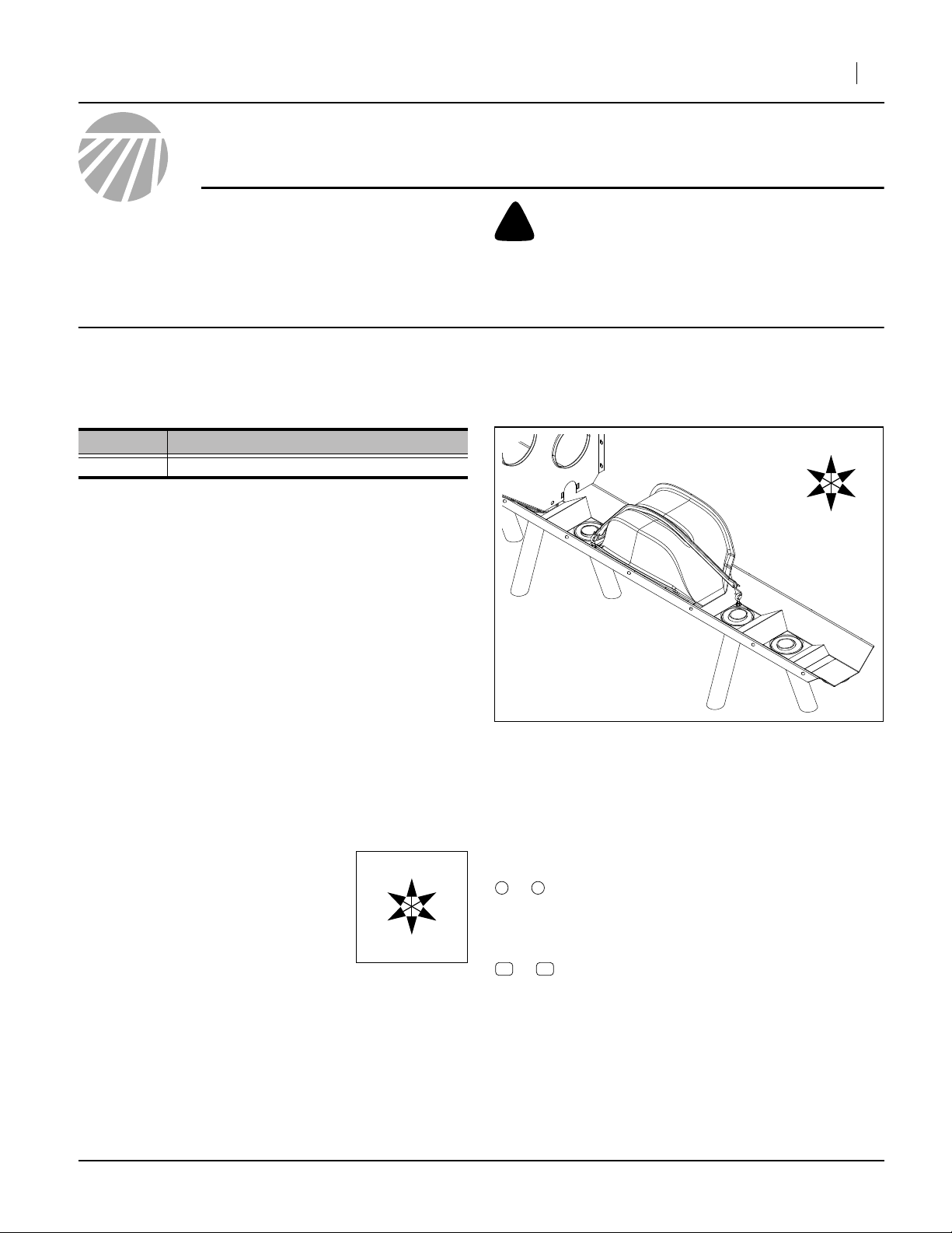
Figure 1
Baffle Strapped in Place
Single-digit callouts identify components in
the currently referenced Figure or Figures.
These numbers may be reused for different
items from page to page.
Two-digit callouts in the range 11 to 19 reference new parts from the new parts lists
beginning on page 6.
29558
©Copyright 2009 Printed 02/15/2010 118-255M
Page 2
2 Baffle Kit
Before You Start
Compatibility
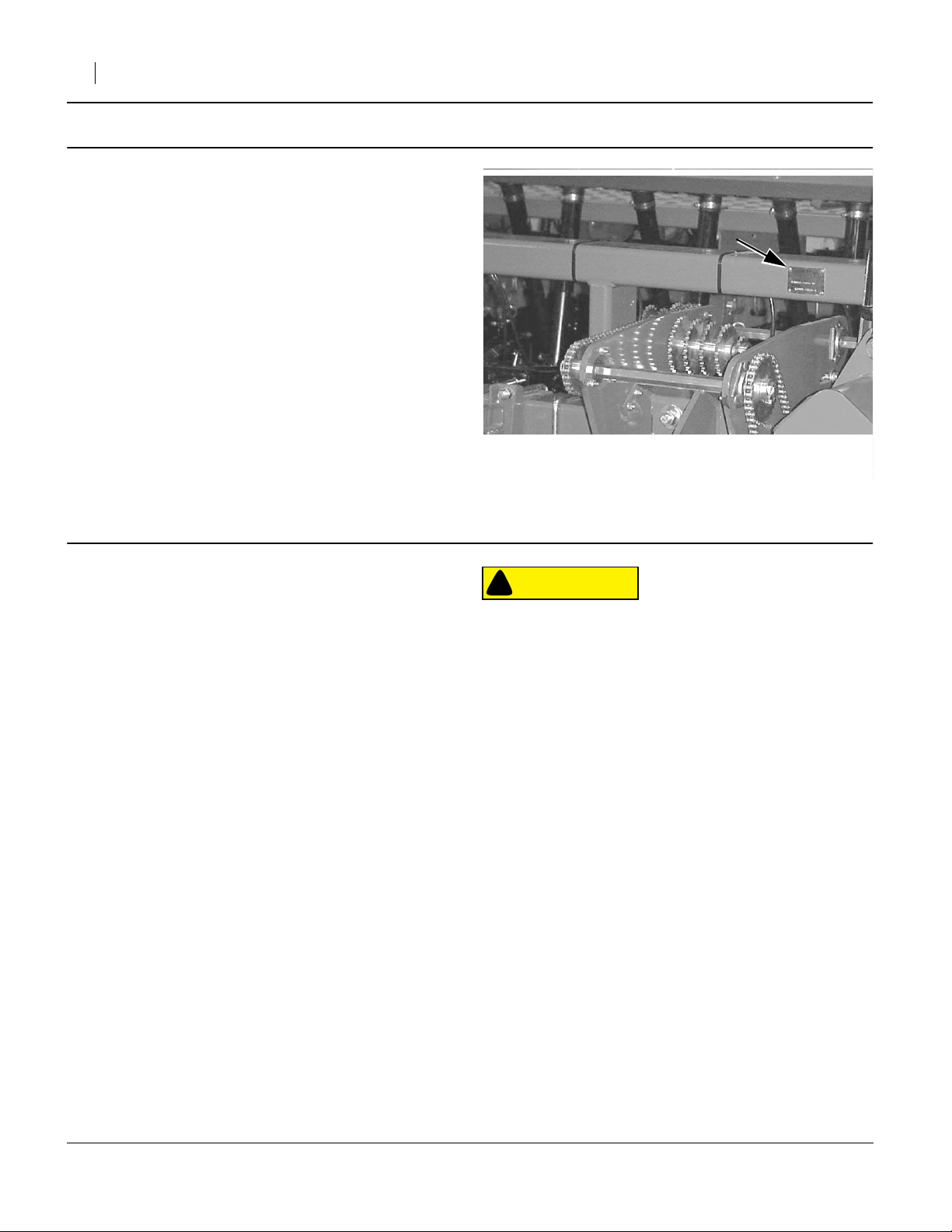
Refer to Figure 2
1. Verify from the serial number plate that the drill is
compatible with this kit.
Inventory
2. Make sure all parts are present (page 6).
Comprehension
3. Review these instructions. Make sure the installers
understand where each part or assembly is
installed, and what tools are required for the task.
Great Plains Mfg., Inc.
Pre-Assembly Preparation
Tools Required
basic hand tools, including:
• indelible marker
• center-punch
• drill bit:
Work Location
4. Clean out the main seed boxes. See Operator Man-
5. Move the drill to a location with:
9
⁄
in (letter size K, or 7.1mm)
32
ual for instructions. If treated seed has been used,
• disconnect seed tubes at meters,
• wash out the boxes,
• thoroughly rinse the boxes, and
• allow them to dry.
Do this in a suitable location other than where the
installation work is to be performed.
• a solid surface to prevent tipping,
• adequate illumination, and;
• clear surface beneath for recovery of any falling
or dropped parts - if the surface is not clear, have
a tarp or drop cloth available.
Figure 2
Serial Number Plate
CAUTION
!
Chemical Hazard
This installation requires contact with interior components of
the main seed boxes. If treated seed has ever been used in the
boxes, follow chemical supplier instructions for protective
equipment and cleaning residue from the seed boxes.
18307
Prepare Drill
6. Install any parking stands and lower the drill.
118-255M 02/15/2010
Page 3
Great Plains Mfg., Inc.
Prepare Tie Point Holes
Identify Baffle Locations
Baffles are symmetrical left-to-right, but are shaped for a
specific front-to-back orientation.
Refer to Figure 3
7. Select four (4) new:
17
817-466C TWIN ROW METER COVER
Temporarily position these wider covers over the
unused meter wells in between the three inner pairs
of seed tubes in each box.
8. Select two (2) new:
18
817-807C 25FT 7 1/2 TO 30TR SPAC COVER
Note that these baffles have “807” molded in.
Temporarily position these narrower covers over
the unused meter wells in between the two outside
pairs of seed tubes in each box.
17
18
Installation Instructions 3
F
L
18
17 17 17 17
Left Seed Box
Baffle Locations
B
Figure 3
R
18
Right Seed Box
29559
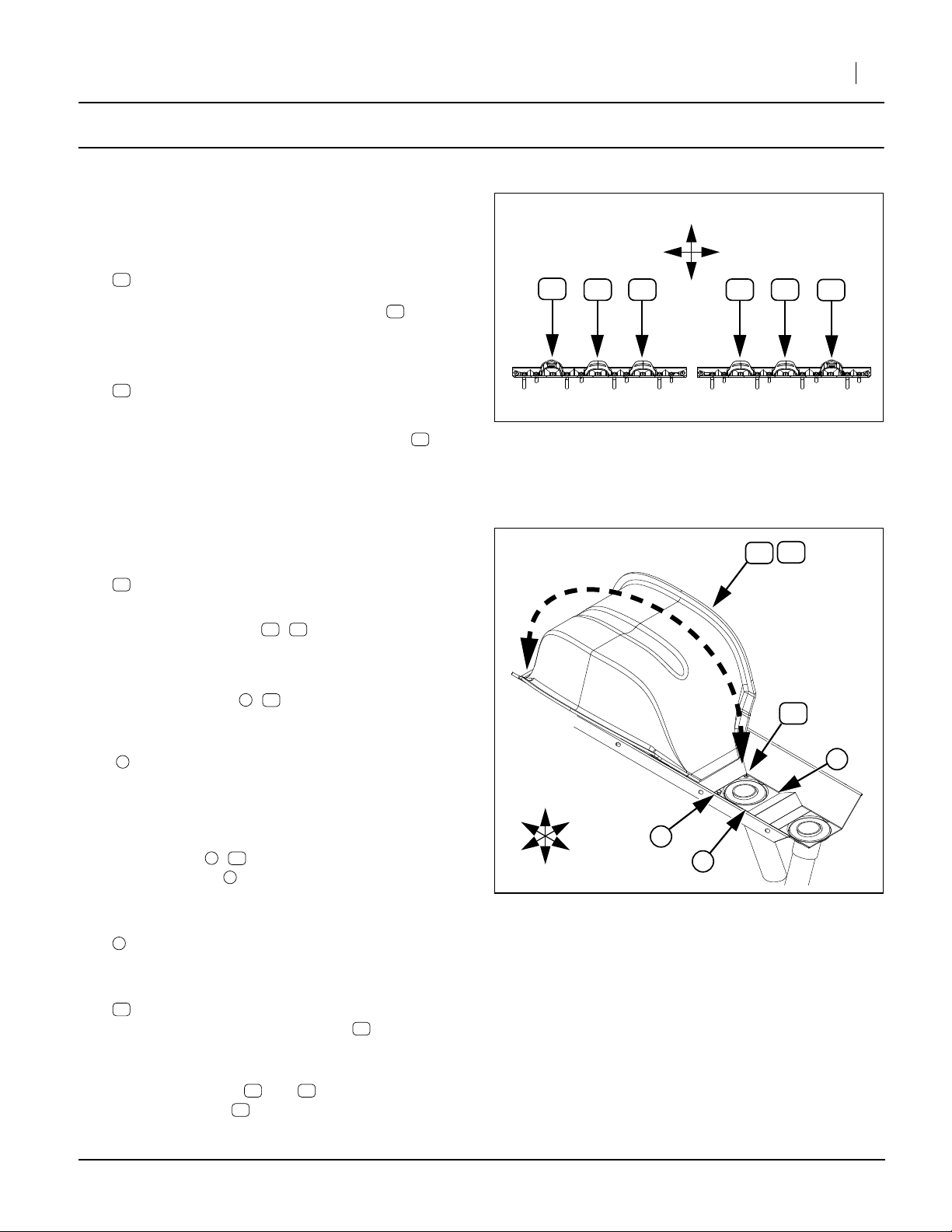
Identify Eyebolt Locations
Refer to Figure 4 (showing both suitable eyebolt locations on
one side of a baffle - only one eyebolt per side is installed)
9. Select one (1) new:
15
804-007C WASHER FLAT 1/4 SAE PLT
This is used as a template for marking holes.
For use, prepared baffles ( , ) are held in place by
straps which take a diagonal path across the top of the
baffle (the dotted double-arrow line in the Figure). They
attach to eyebolts supplied in this kit, which are installed
in the nearest corners ( , ) of the adjacent seed box
wells.
Depending on vintage, your drill may or may not have
1
bolts in suitable locations. If it does, these bolts may
be replaced with the eyebolts in this kit (holes are drilled
otherwise).
10. Check the seed tube wells immediately adjacent to
the baffles. Suitable hole locations are in the cor-
ners closest ( , ) to the baffle. Do not use the
outside corners (this can cause the strap to inter-
fere with the sliding seed tube, as well as obstruct
seed flow).
1
Mark any bolt heads at suitable locations. At the
diagonally opposite location, mark any bolt head
there, or use the washer to mark a hole location.
115
17 18
115
0
R
F
U
D
B
1
L
Figure 4
Bolt Hole Requirement
17
18
15
0
0
29556
15
If there are no suitable existing holes on a side,
chose a location. Slide the washer into the corner. Use the washer hole as a template to mark the
hole location.
11. Remove all baffles and .
Save the washer .
02/15/2010 118-255M
17 18
15
15
Page 4

4 Baffle Kit
Prepare Baffles
Apply Initial Foam Seals
Refer to Figure 5
12. Select all baffles ( , ).
Clean, de-grease and dry the lower flanged edges
of each baffle. This edge is the surface that will be
against the seed box walls and well dividers when in
use.
13. Select both rolls of the new:
19
890-750C FOAM SEAL 1/2 X 3/4 X 204
14. Apply a single continuous layer of foam seal to the
flanged edges.
Test Fit Baffles
Refer to Figure 3 on page 3
15. Place each baffle in the same locations used for
determining the hole locations at step 7 and step 8.
16. Press down firmly and check the entire flange for
gaps.
17. Mark the first foam layer at any regions showing
gaps.
17 18
17
18
19
Figure 5
First Layer of Foam Seal
Great Plains Mfg., Inc.
19253
Apply Additional Foam Seal (As Needed)
Refer to Figure 6
18. Cut and apply additional foam seal at marked
regions .
19. Place baffle at its assigned location in the seed box,
and re-check seal seating.
20. Mark baffles (on foam) with numbers of adjacent
rows. Unless all baffles with the same part number
received identical foam application, baffles are now
customized to specific locations in the seed boxes.
2
19
Prepare Eyebolt Locations
21. Use a punch to make a detent at the center of any
locations, marked at step 10, where a hole needs to
be drilled.
22. Use the
tions.
23. Remove all marked bolts. These bolts, washers and
nuts are not re-used. No precautions need to be
taken to secure parts held together by removed
bolts.
9
⁄
in drill to make holes at all marked loca-
32
2
Figure 6
Second Layer of Foam Seal
2
19254
118-255M 02/15/2010
Page 5

Great Plains Mfg., Inc.
Install Eyebolts
Refer to Figure 7
24. Working from drill left to right, select one (1) set:
12
802-233C SP EYE 1/4-20X2 3/4
14
804-006C WASHER LOCK SPRING 1/4 PLT
and two (2) sets:
15
804-007C WASHER FLAT 1/4 SAE PLT
13
803-006C NUT HEX 1/4-20 PLT
Installation Instructions 5
12
13
15
25. Spin one nut fully onto the eyebolt . Add a flat
washer .
26. Insert this eyebolt assembly into a strap hole .
27. From beneath the drill add another flat washer ,
lock washer , and secure with second nut .
There is no preferred orientation for the eye of the
eyebolt.
28. Repeat for all 12 eyebolt locations .
13 12
15
3
15
14 13
3
Install Baffles
Refer to Figure 8
29. Place all baffles ( , ) in their assigned positions.
30. Select six (6)new:
16
816-169C TARP STRAP 15 WITH HOOKS
Secure each baffle by hooking strap to
eyebolts .
31. Re-check seal seating with strap in place. Apply
additional foam seal as required.
32. Select all remaining foam seal . Store it under the
left-most baffle.
12
17 18
16
19
19
Baffle Operation
R
F
12
U
D
15
14
13
B
L
Figure 7
Eyebolt Installation
Figure 8
Install Baffle
3
29557
1817
16
12
29558
Baffles slightly reduce the raw capacity of the seed
boxes (the usable capacity remains about the same).
There are no other operational considerations.
Baffle Maintenance
Baffle: Seals
Seasonally
When cleaning out the seed box for the season, inspect
the seals on each baffle, or remove the baffles and check
for any seed flow under the baffle. Add foam seal as necessary (spare foam seal stored under left-most baffle).
02/15/2010 118-255M
29558
Page 6

6 Baffle Kit
Appendix
New Parts
Quantities are units (“ea”) except for foam seal, where
each of the two supplied is a 204in (518cm) roll.
Great Plains Mfg., Inc.
The part call-out numbers in this list match all Figures in
these installation instructions. Part descriptions match
those in your updated Parts Manual.
12
19
13
15
15
14
16
13
Fi S
118-254A Kit Contents
Callout
11
12
13
14
15
16
17
18
19
Quantity
in Kit
1 118-255M
12 802-233C
24 803-006C
12 804-006C
24 804-007C
6 816-169C
4 817-466C
2 817-807C
2 890-750C
Part Number
17
Figure 9
New Parts
Part Description
MANUAL BAFFLE KIT 20P 30TR
SP EYE 1/4-20X2 3/4
NUT HEX 1/4-20 PLT
WASHER LOCK SPRING 1/4 PLT
WASHER FLAT 1/4 SAE PLT
TARP STRAP 15 WITH HOOKS
TWIN ROW METER COVER
25FT 7 1/2 TO 30TR SPAC COVER
FOAM SEAL 1/2 X 3/4 X 204
18
29555
Abbreviations
20P
30TR
HEX
PLT
118-255M 02/15/2010
20 Series Precision
30 Inch Twin Row
Hexagonal
Plated
SAE
SP
SPAC
X
Society of Automotive Engineers (standards)
Special
Spacing
By
Page 7

Great Plains Mfg., Inc.
Torque Values
Installation Instructions 7
Bolt
Size
in-tpi
1
⁄4-20
1
⁄4-28
5
⁄16-18
5
⁄16-24
3
⁄8-16
3
⁄8-24
7
⁄16-14
7
⁄16-20
1
⁄2-13
1
⁄2-20
9
⁄16-12
9
⁄16-18
5
⁄8-11
5
⁄8-18
3
⁄4-10
3
⁄4-16
7
⁄8-9
7
⁄8-14
1-8
1-12
11⁄8-7
11⁄8-12
11⁄4-7
11⁄4-12
13⁄8-6
13⁄8-12
11⁄2-6
11⁄2-12
Bolt Head Identification
Bolt Head Identification
Bolt
Size
Grade 2 Grade 5 Grade 8 Class 5.8 Class 8.8 Class 10.9
1
N-m2ft-lb
7.4 5.6 11 8 16 12
8.5 6 13 10 18 14
15 11 24 17 33 25
17 13 26 19 37 27
27 20 42 31 59 44
31 22 47 35 67 49
43 32 67 49 95 70
49 36 75 55 105 78
66 49 105 76 145 105
75 55 115 85 165 120
95 70 150 110 210 155
105 79 165 120 235 170
130 97 205 150 285 210
150 110 230 170 325 240
235 170 360 265 510 375
260 190 405 295 570 420
225 165 585 430 820 605
250 185 640 475 905 670
340 250 875 645 1230 910
370 275 955 705 1350 995
480 355 1080 795 1750 1290
540 395 1210 890 1960 1440
680 500 1520 1120 2460 1820
750 555 1680 1240 2730 2010
890 655 1990 1470 3230 2380
1010 745 2270 1670 3680 2710
1180 870 2640 1950 4290 3160
1330 980 2970 2190 4820 3560
Torque tolerance + 0%, -15% of torquing values. Unless otherwise specified use torque values listed above.
3
N-m ft-lb N-m ft-lb
mm x pitch
M 5 X 0.8
M 6 X 1
M 8 X 1.25
M 8 X 1
M10 X 1.5
M10 X 0.75
M12 X 1.75
M12 X 1.5
M12 X 1
M14 X 2
M14 X 1.5
M16 X 2
M16 X 1.5
M18 X 2.5
M18 X 1.5
M20 X 2.5
M20 X 1.5
M24 X 3
M24 X 2
M30 X 3.5
M30 X 2
M36 X 3.5
M36 X 2
1. in-tpi = nominal thread diameter in inches-threads per inch
2. N· m = newton-meters
3. ft-lb = foot pounds
4. mm x pitch = nominal thread diameter in millimeters x thread
pitch
4
5.8 8.8 10.9
N-m ft-lb N-m ft-lb N-m ft-lb
43659 7
7 5 11 8 15 11
17 12 26 19 36 27
18 13 28 21 39 29
33 24 52 39 72 53
39 29 61 45 85 62
58 42 91 67 125 93
60 44 95 70 130 97
90 66 105 77 145 105
92 68 145 105 200 150
99 73 155 115 215 160
145 105 225 165 315 230
155 115 240 180 335 245
195 145 310 230 405 300
220 165 350 260 485 355
280 205 440 325 610 450
310 230 650 480 900 665
480 355 760 560 1050 780
525 390 830 610 1150 845
960 705 1510 1120 2100 1550
1060 785 1680 1240 2320 1710
1730 1270 2650 1950 3660 2700
1880 1380 2960 2190 4100 3220
02/15/2010 118-255M
Page 8

8 Baffle Kit
Great Plains Mfg., Inc.
Great Plains Manufacturing, Inc.
Corporate Office P.O. Box 5060
Salina, Kansas 67402-5060 USA
118-255M 02/15/2010
 Loading...