

Page 1
Great Plains Mfg., Inc.
Installation Instructions
3-Point Precision Seeding System
Marker Option
Used with:
• 1510P and 1520P
• 2010P and 2020P
General Information
When you see this symbol, the subsequent instructions and
warnings are serious - follow without exception. Your life and
!
!
the lives of others depend on it!
These instructions explain how to install the Marker Option on the 15 and 20 foot 3-point Precision
Seeding Systems.
The markers fold and unfold hydraulically for field
operation. The marker disks leave a line for the
drill operator to follow on the next field pass. Markers are mounted on the drill frame and require two
hydraulic remote valves on the tractor. A sequence valve is available so markers can be
operated on one hydraulic circuit.
These instructions apply to:
113-691A 15P Single LH Marker Package
113-692A 15P Dual Marker Package
113-693A 20P Single LH Marker Package
113-694A 20P Dual Marker Package
Assembly Instructions
Marker Assembly
Refer to Figure 1
.
Manual Update
Refer to the 3-Point Precision Seeding System
operator’s manual for detailed information on
safely operating, adjusting, troubleshooting and
maintaining the Marker Option. Refer to the parts
manual for part identification.
118-732M 1510P and 1520P Operator’s
Manual
118-732P 1510P and 1520P Parts Manual
118-740M 2010P and 2020P Operator’s
Manual
118-740P 2010P and 2020P Parts Manual
Before You Start
Page 7 is a detailed listing of parts included in the
Marker Option package. Use this list to inventory
parts received.
15 foot A = 7 3/8 inches
20 foot A - 6 1/2 inches
1. Lower drill into field position. Allow 9 feet on
each end of a 15-foot drill and 11 feet on each
end of a 20-foot drill for marker assembly.
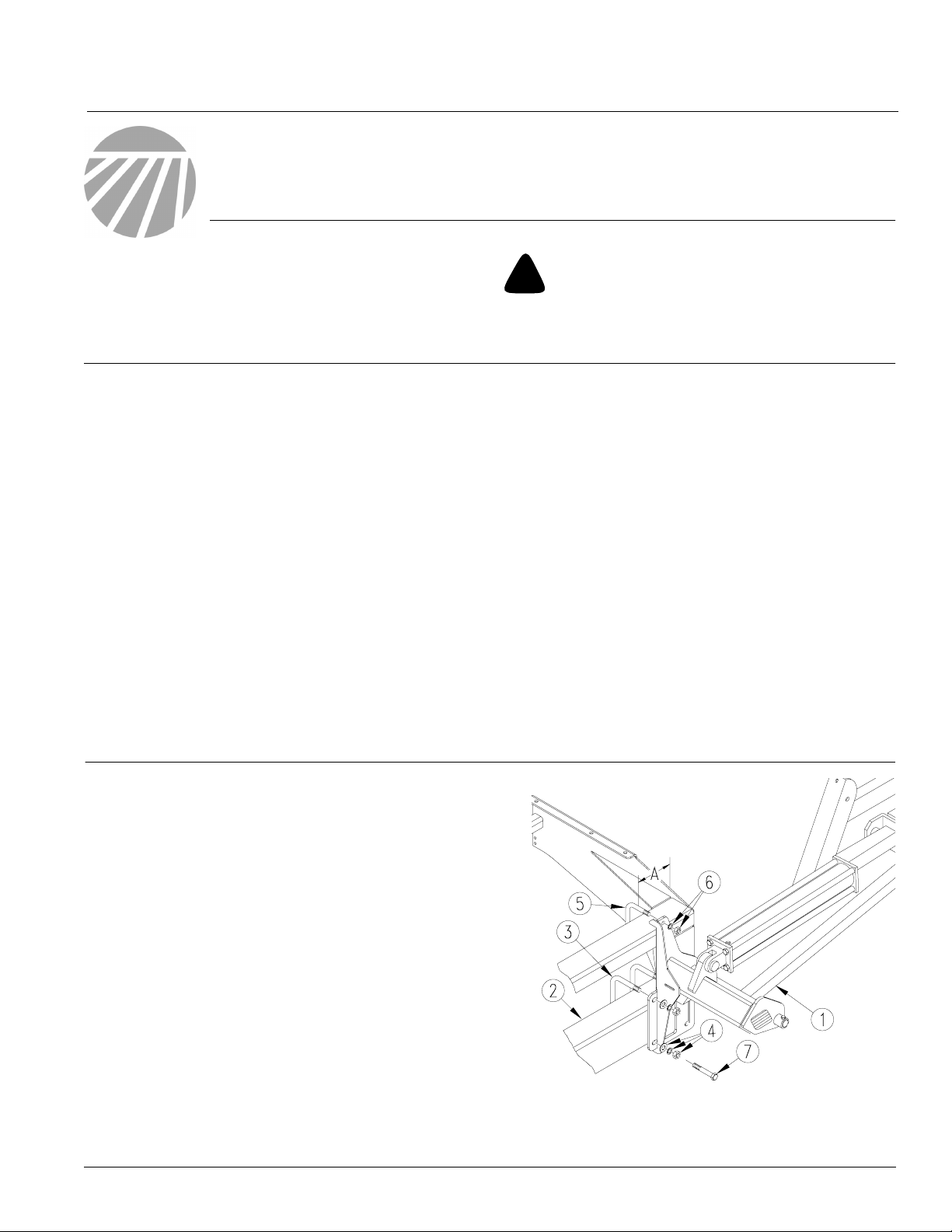
2. Mount first marker section (1) on drill 7 x 5
inch frame tube (2). Mount marker at the end of
the drill using dimension "A" as a starting point.
Some row spacings will require the mount to
be adjusted in or out from this starting point.
3. Secure marker section with 5/8 inch u-bolts
(3), lock washers, washers and nuts (4). and
1/2 inch u-bolts (5), lock washers and nuts (6).
NOTE: On the 20-foot drill with 15 inch row spacing, the last opener is bolted to the marker mount
using 5/8 x 6 1/2 inch straight bolts (7).
© Copyright 2000 Printed
1/3/2000
Figure 1
First Marker Section Assembly
113-688M
18413
Page 2
Marker Option
2
Great Plains Mfg., Inc.
Refer to
Figure 2
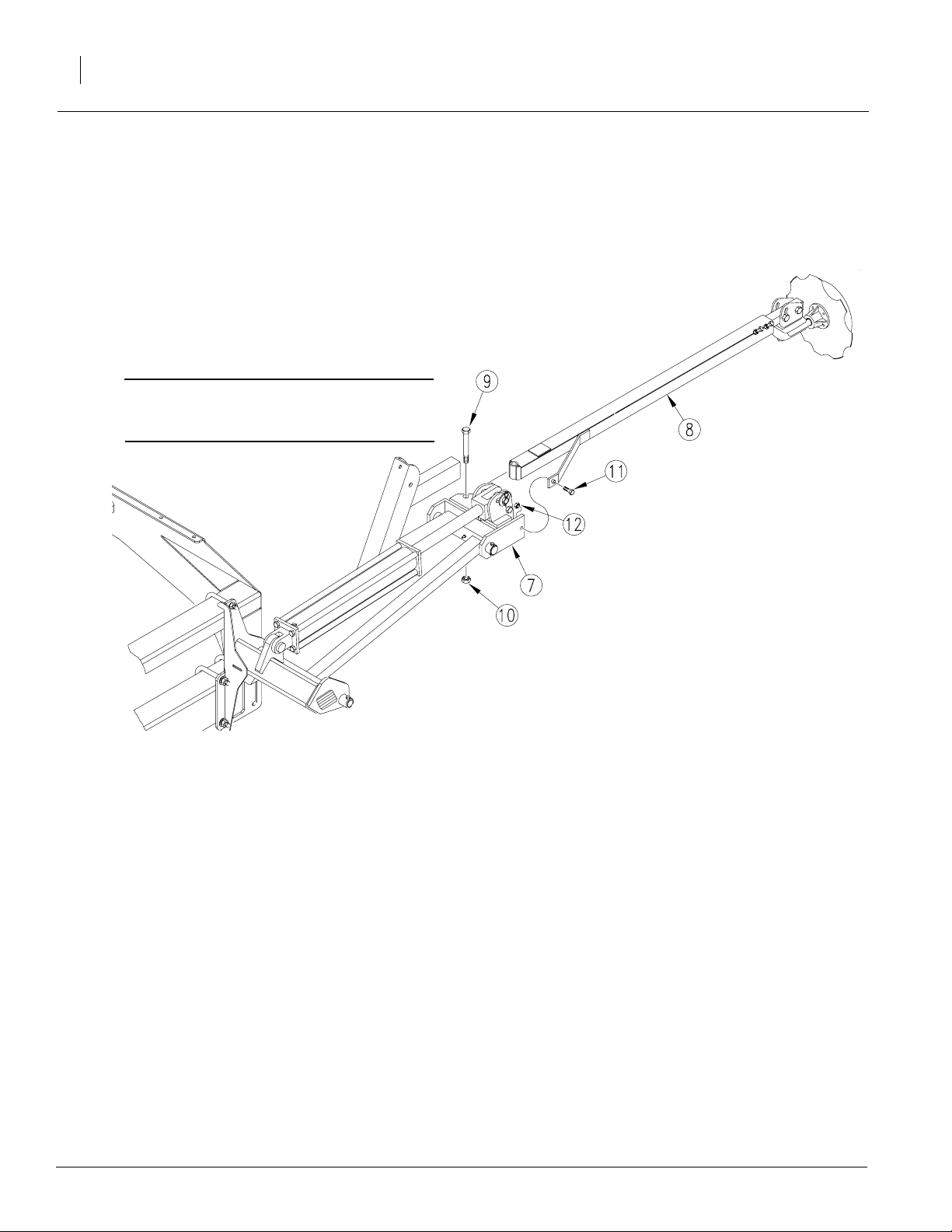
4. Remove port plugs on cylinder and carefully
unfold first marker section. Rotate hinge section (7) into a horizontal position.
5. Align holes of break-away section (8) with
holes in hinge section. Bolt sections together
using a 5/8-inch pivot bolt (9), lock nut (10), 3/
8-by-1 3/4-inch, grade 2 shear bolt (11) and
lock nut (12).
IMPORTANT: Be sure shear bolt is a grade 2
bolt. Failure to use a grade 2 bolt can cause
marker damage.
Marker Breakaway Assembly
6. Repeat steps for other marker.
7. To adjust markers, refer to Marker Adjust-
ments in the operator’s manual.
Figure 2
18414
113-688M 3/3/2006
Page 3
Great Plains Mfg., Inc.
Carrier Assembly for 20P drill
To assemble carrier onto drill frame, refer to Figure 3
.
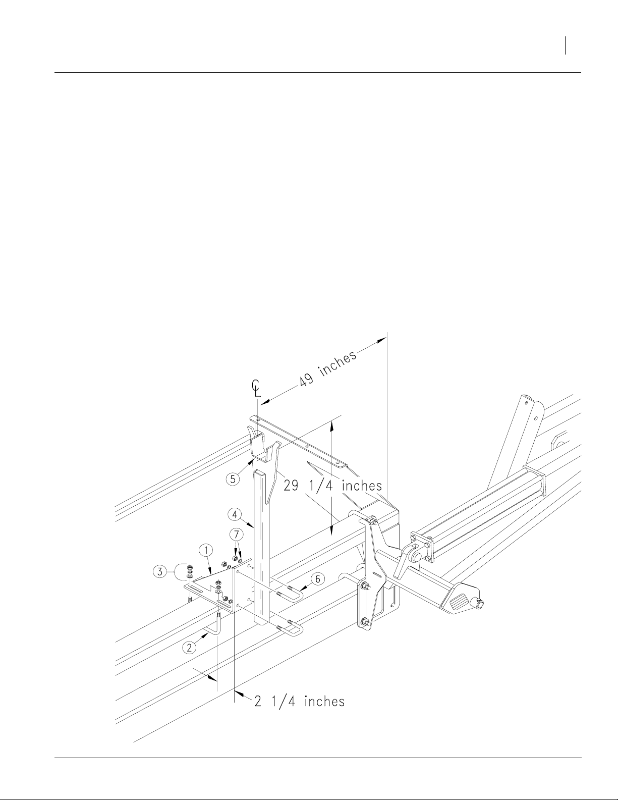
1. Assemble transport-carrier mount (1) on drill
frame. Center mount 49 inches from outside
end of drill frame. Use 1/2 x 6 1/32 x 7-inch
u-bolts (2), flat washers, lock washers and
hex nuts (3). Slide mount forward so its leading edge is about 2 1/4 inches ahead of front
edge of drill frame tube.
2. Bolt transport carrier (4) to transport-carrier
mount so top surface of saddle (5) is about
29 1/4 inches above top of drill frame tube.
Secure transport carrier with 1/2 x 2 x 3-inch
u-bolts (6), lock washers and hex nuts (7).
3. After installing and bleeding hydraulics, trans-
port carrier may require further adjustment.
When folded, the second marker section
should rest in the transport-carrier saddle.
Installation Instructions
3
3/3/2006
Figure 3
18415
Carrier Assembly
113-688M
Page 4
Marker Option
4
Installing Marker Hydraulics
Without Sequence Valve
Refer to Figure 4.
1. Install elbow fittings (1) in cylinder ports.
2. At rod end of each cylinder, install an adaptor
Great Plains Mfg., Inc.
(2) into elbow fitting. Install a needle valve (3)
in adaptor.
3. Connect hydraulic hoses to fittings and route
hydraulic hoses to tractor outlets. Route hydraulic hoses through transport-carrier mount
at cutout. Use black cable ties to secure hydraulic hoses to drill frame.
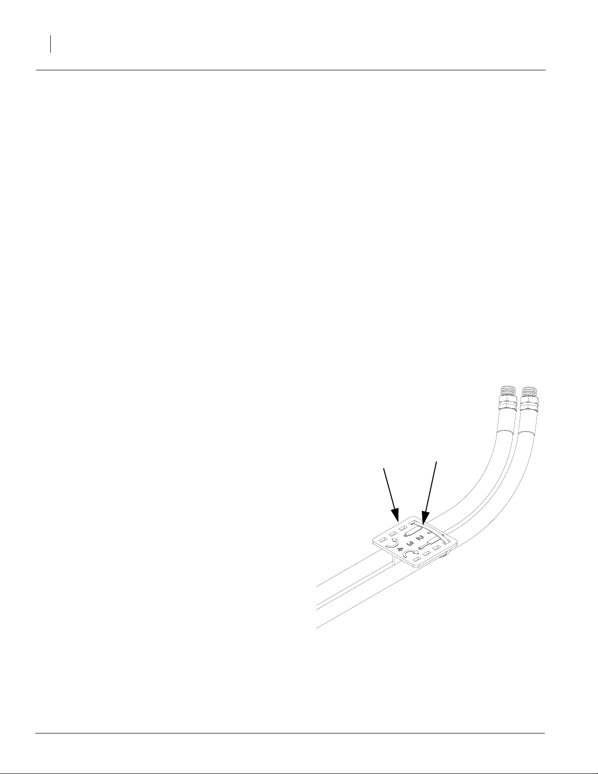
4. Using orange cable ties, secure a plastic hose
label
, see Figure 5, to each pair of hydraulic
hoses near tractor outlets.
5. Proceed with "Bleeding Marker Hydraulics"
on page 6.
Needle Valve Assembly
Plastic hose
label
Figure 4
Cable tie
17642
Figure 5
Hose label and cable tie
113-688M 3/3/2006
17641
Page 5

Great Plains Mfg., Inc.
With Sequence Valve
Refer to Figure 6
.
1. Mount sequence valve (1) on drill using
mounting plate (2). Bolt plate to inside end of
left-hand-box panel (3) using one 1/2-inch
hex bolt (4).
2. Bolt valve to mounting plate with two 3/8 x
3/4-inch hex bolts and lock washers (5).
3. Install elbow fittings in cylinder ports. Discard
adaptor fitting and two needle valves provided
in marker kit.
4. Use hoses provided to connect valve ports to
cylinders. Refer to
Figure 7
for port connec-
tions.
5. Connect your own hydraulic hoses to ports on
front of valve. Route hoses to tractor outlets.
Installation Instructions
5
6. Using orange cable tie, secure plastic hose
label, see Figure 5, to hydraulic hoses near
tractor outlets.
7. Proceed with "Bleeding Marker Hydraulics"
on page 6.
Figure 6
Sequence Valve Assembly
18416
3/3/2006
Figure 7
Hydraulic Hose Connection
18417
113-688M
Page 6

Marker Option
6
Bleeding Marker Hydraulics
You may be injured if hit by a folding or unfolding
marker. Markers may fall quickly and unexpectedly if
the hydraulics fail. Never allow anyone near the drill
when folding or unfolding the markers.
Escaping fluid under pressure can have sufficient pressure to penetrate the skin. Check all hydraulic lines
and fittings before applying pressure. Fluid escaping
from a very small hole can be almost invisible. Use paper or cardboard, not body parts, and wear heavy
gloves to check for suspected leaks. If injured, seek
medical assistance from a doctor that is familiar with
this type of injury. Foreign fluids in the tissue must be
surgically removed within a few hours or gangrene
will result.
!
CAUTION!
!
WARNING!
Great Plains Mfg., Inc.
1. Check that tractor hydraulic reservoir is full.
2. With both markers lowered into field position,
loosen hydraulic-hose fittings at rod and base
ends of marker cylinders. If applicable, loosen
fittings on back side of sequence valve.
IMPORTANT: Never bleed an O-ring fitting. Instead, bleed a nearby pipe or JIC fitting.
3. With tractor idling, activate tractor hydraulic
valve until oil seeps out around a loosened fitting. Tighten that fitting.
IMPORTANT: JIC fittings do not require high
torque. JIC and O-ring fittings do not require
sealant. Always use liquid pipe sealant when
adding or replacing pipe-thread fittings. To
avoid cracking hydraulic fittings from over
tightening, do not use plastic sealant tape.
4. Reactivate tractor hydraulic valve until oil
seeps out around another loosened fitting.
Tighten that fitting. Repeat process until all
loosened fitting have been bled and tightened.
5. Adjust marker folding to a safe speed. Refer
to "Marker Adjustments" in the operator’s
manual.
113-688M 3/3/2006
Page 7

Great Plains Mfg., Inc.
113-691A MARKER, 3PT 15-P SINGLE LH
Your kit includes:
Qty. Part No. Part Description
1 811-017C HH1/4R1 156 3/8MNPT 1/2MNP
1 811-300C HH1/4R1 176 3/8MNPT 1/2MNP
1 113-180H LH FIRST SECTION
1 113-191H 2 SECTION MARKER BREAKAWAY
1 113-248D PIN 1 OD X 4.34 USABLE
1 113-312D FIRST PIVOT SHAFT
1 113-313D SECOND PIVOT SHAFT
1 113-324D CYLINDER STOP
2 113-325D STOP BUSHING
1 113-351D MARKER TUBE 42 LG
1 113-468H LIFT LUG CHANNEL L.H.
2 113-491D ADJUST MOUNT SPACER TUBE
1 113-503H MARKER DISK ADJUST MOUNT
1 113-563S MARKER DISC & HUB ASSEMBLY
1 113-689H MARKER MOUNT LH
2 800-001C GREASE ZERK STRAIGHT 1/4-28
2 801-054C SCREW SET SQ HD 1/2-13X1 GR5
4 802-099C HHCS 1/2-13X3 1/4 GR5
2 802-115C HHCS 5/16-18X2 GR5
1 802-249C HHCS 1/2-13X4 1/2 GR5 SPTHD
1 802-253C HHCS 3/8-16X1 3/4 GR2
1 802-254C HHCS 5/8-11X5 1/2 GR5
2 803-011C NUT LOCK 5/16-18 PLT
1 803-013C NUT LOCK 3/8-16 PLT
1 803-019C NUT LOCK 1/2-13 PLT
4 803-020C NUT HEX 1/2-13 PLT
1 803-024C NUT LOCK 5/8-11 PLT
2 803-036C NUT HEX JAM 1/2-13 PLT
4 804-015C WASHER LOCK SPRING 1/2 PLT
4 804-017C WASHER FLAT 1/2 USS PLT
2 804-029C WASHER FLAT 1 SAE
2 805-058C PIN COTTER 3/16 X 2
1 810-205C CYL 2X20X1.12 ROD (TIE) 1
1 818-229C DECAL AMBER REFLECTOR
2 818-682C DECAL WARNING PINCH/CRUSH MRKR
2 803-020C NUT HEX 1/2-13 PLT
4 803-021C NUT HEX 5/8-11 PLT
2 804-015C WASHER LOCK SPRING 1/2 PLT
4 804-021C WASHER FLAT 5/8 SAE PLT
4 804-022C WASHER LOCK SPRING 5/8 PLT
2 806-053C U-BOLT 5/8-11 X 7 1/32 X 6 1/2
1 806-122C U-BOLT 1/2-13 X 3 1/32 X 6
1 810-058C VALVE 3/8 NEEDLE
1 811-044C AD 3/8MNPT
2 811-281C EL 3/8FNPT 9/16MORB
Installation Instructions
7
113-688M3/3/2006
Page 8

Marker Option
8
113-692A MARKER, 3PT 15-P DUAL
Your kit includes:
Qty. Part No. Part Description
2 811-017C HH1/4R1 156 3/8MNPT 1/2MNP
2 811-300C HH1/4R1 176 3/8MNPT 1/2MNP
1 113-180H LH FIRST SECTION
1 113-188H RH FIRST SECTION
2 113-191H 2 SECTION MARKER BREAKAWAY
2 113-248D PIN 1 OD X 4.34 USABLE
2 113-312D FIRST PIVOT SHAFT
2 113-313D SECOND PIVOT SHAFT
2 113-324D CYLINDER STOP
4 113-325D STOP BUSHING
2 113-351D MARKER TUBE 42 LG
1 113-467H LIFT LUG CHANNEL R.H.
1 113-468H LIFT LUG CHANNEL L.H.
4 113-491D ADJUST MOUNT SPACER TUBE
2 113-503H MARKER DISK ADJUST MOUNT
2 113-563S MARKER DISC & HUB ASSEMBLY
1 113-689H MARKER MOUNT LH
1 113-690H MARKER MOUNT RH
4 800-001C GREASE ZERK STRAIGHT 1/4-28
4 801-054C SCREW SET SQ HD 1/2-13X1 GR5
8 802-099C HHCS 1/2-13X3 1/4 GR5
4 802-115C HHCS 5/16-18X2 GR5
2 802-249C HHCS 1/2-13X4 1/2 GR5 SPTHD
2 802-253C HHCS 3/8-16X1 3/4 GR2
2 802-254C HHCS 5/8-11X5 1/2 GR5
4 803-011C NUT LOCK 5/16-18 PLT
2 803-013C NUT LOCK 3/8-16 PLT
2 803-019C NUT LOCK 1/2-13 PLT
12 803-020C NUT HEX 1/2-13 PLT
2 803-024C NUT LOCK 5/8-11 PLT
4 803-036C NUT HEX JAM 1/2-13 PLT
12 804-015C WASHER LOCK SPRING 1/2 PLT
12 804-017C WASHER FLAT 1/2 USS PLT
4 804-029C WASHER FLAT 1 SAE
4 805-058C PIN COTTER 3/16 X 2
2 810-205C CYL 2X20X1.12 ROD (TIE) 1 PIN
2 818-229C DECAL AMBER REFLECTOR
4 818-682C DECAL WARNING PINCH/CRUSH
4 803-020C NUT HEX 1/2-13 PLT
8 803-021C NUT HEX 5/8-11 PLT
4 804-015C WASHER LOCK SPRING 1/2 PLT
8 804-021C WASHER FLAT 5/8 SAE PLT
8 804-022C WASHER LOCK SPRING 5/8 PLT
4 806-053C U-BOLT 5/8-11 X 7 1/32 X 6 1/2
2 806-122C U-BOLT 1/2-13 X 3 1/32 X 6
2 810-058C VALVE 3/8 NEEDLE
2 811-044C AD 3/8MNPT
4 811-281C EL 3/8FNPT 9/16MORB
1 113-666D MARKER REVERSING ADAPT PLATE 1
1 113-667D MARKER REVERSING ADAPT PLATE 2
2 802-041C HHCS 1/2-13X3 1/2 GR5
Great Plains Mfg., Inc.
3/3/2006
113-688M
Page 9

Great Plains Mfg., Inc.
113-693A MARKER, 3-PT 20-P SINGLE LH
Your kit includes:
Qty. Part No. Part Description
1 811-015C HH1/4R1 192 3/8MNPT 1/2MNPT
1 811-297C SP HH1/4R1 212 3/8MNPT-W/AD
1 113-180H LH FIRST SECTION
1 113-248D PIN 1 OD X 4.34 USABLE
1 113-312D FIRST PIVOT SHAFT
1 113-313D SECOND PIVOT SHAFT
1 113-324D CYLINDER STOP
2 113-325D STOP BUSHING
1 113-354D 13’ MARKER TUBE 46 1/2 LONG
1 113-468H LIFT LUG CHANNEL L.H.
2 113-491D ADJUST MOUNT SPACER TUBE
1 113-503H MARKER DISK ADJUST MOUNT
1 113-563S MARKER DISC & HUB ASSEMBLY
1 113-646H 20’ MARKER BREAKAWAY
1 113-689H MARKER MOUNT LH
2 800-001C GREASE ZERK STRAIGHT 1/4-28
2 801-054C SCREW SET SQ HD 1/2-13X1 GR5
4 802-099C HHCS 1/2-13X3 1/4 GR5
2 802-115C HHCS 5/16-18X2 GR5
1 802-249C HHCS 1/2-13X4 1/2 GR5 SPTHD
1 802-253C HHCS 3/8-16X1 3/4 GR2
1 802-254C HHCS 5/8-11X5 1/2 GR5
2 803-011C NUT LOCK 5/16-18 PLT
1 803-013C NUT LOCK 3/8-16 PLT
1 803-019C NUT LOCK 1/2-13 PLT
4 803-020C NUT HEX 1/2-13 PLT
1 803-024C NUT LOCK 5/8-11 PLT
2 803-036C NUT HEX JAM 1/2-13 PLT
4 804-015C WASHER LOCK SPRING 1/2 PLT
4 804-017C WASHER FLAT 1/2 USS PLT
2 804-029C WASHER FLAT 1 SAE
1 805-058C PIN COTTER 3/16 X 2
1 810-205C CYL 2X20X1.12 ROD (TIE) 1 PIN
1 818-229C DECAL AMBER REFLECTOR
2 818-682C DECAL WARNING PINCH/CRUSH
1 113-568H MARKER TRANSPORT MOUNT
1 113-677H 20 BM MARKER TRANSPORT CARRIER
4 800-035C CABLE TIE 28 LONG
4 802-335C HHCS 5/8-11X6 1/2 GR5
10 803-020C NUT HEX 1/2-13 PLT
4 803-021C NUT HEX 5/8-11 PLT
2 803-036C NUT HEX JAM 1/2-13 PLT
10 804-015C WASHER LOCK SPRING 1/2 PLT
4 804-017C WASHER FLAT 1/2 USS PLT
4 804-021C WASHER FLAT 5/8 SAE PLT
4 804-022C WASHER LOCK SPRING 5/8 PLT
2 806-005C U-BOLT 1/2-13 X 2 X 3 GR 5
2 806-053C U-BOLT 5/8-11 X 7 1/32 X 6 1/2
1 806-122C U-BOLT 1/2-13 X 3 1/32 X 6
2 806-159C U-BOLT 1/2-13 X 5 1/32 X 4
1 810-058C VALVE 3/8 NEEDLE
1 811-044C AD 3/8MNPT
2 811-281C EL 3/8FNPT 9/16MORB
Installation Instructions
9
113-688M3/3/2006
Page 10

Marker Option
10
113-694A MARKER, 3PT 20-P DUAL
Your kit includes:
Qty. Part No. Part Description
2 811-015C HH1/4R1 192 3/8MNPT 1/2MNPT
2 811-297C SP HH1/4R1 212 3/8MNPT-W/AD
1 113-597V 20’ DUAL FF HOSE BUNDLE
1 113-180H LH FIRST SECTION
1 113-188H RH FIRST SECTION
2 113-248D PIN 1 OD X 4.34 USABLE
2 113-312D FIRST PIVOT SHAFT
2 113-313D SECOND PIVOT SHAFT
2 113-324D CYLINDER STOP
4 113-325D STOP BUSHING
2 113-354D 13’ MARKER TUBE 46 1/2 LONG
1 113-467H LIFT LUG CHANNEL R.H.
1 113-468H LIFT LUG CHANNEL L.H.
4 113-491D ADJUST MOUNT SPACER TUBE
2 113-503H MARKER DISK ADJUST MOUNT
2 113-563S MARKER DISC & HUB ASSEMBLY
2 113-646H 20’ MARKER BREAKAWAY
1 113-689H MARKER MOUNT LH
1 113-690H MARKER MOUNT RH
4 800-001C GREASE ZERK STRAIGHT 1/4-28
4 801-054C SCREW SET SQ HD 1/2-13X1 GR5
8 802-099C HHCS 1/2-13X3 1/4 GR5
4 802-115C HHCS 5/16-18X2 GR5
2 802-249C HHCS 1/2-13X4 1/2 GR5 SPTHD
2 802-253C HHCS 3/8-16X1 3/4 GR2
2 802-254C HHCS 5/8-11X5 1/2 GR5
4 803-011C NUT LOCK 5/16-18 PLT
2 803-013C NUT LOCK 3/8-16 PLT
2 803-019C NUT LOCK 1/2-13 PLT
12 803-020C NUT HEX 1/2-13 PLT
2 803-024C NUT LOCK 5/8-11 PLT
4 803-036C NUT HEX JAM 1/2-13 PLT
12 804-015C WASHER LOCK SPRING 1/2 PLT
12 804-017C WASHER FLAT 1/2 USS PLT
4 804-029C WASHER FLAT 1 SAE
4 805-058C PIN COTTER 3/16 X 2
2 810-205C CYL 2X20X1.12 ROD (TIE) 1 PIN
2 818-229C DECAL AMBER REFLECTOR
4 818-682C DECAL WARNING PINCH/CRUSH
2 113-568H MARKER TRANSPORT MOUNT
2 113-677H 20 BM MARKER TRANSPORT CARRIER
8 800-035C CABLE TIE 28 LONG
4 802-335C HHCS 5/8-11X6 1/2 GR5
20 803-020C NUT HEX 1/2-13 PLT
8 803-021C NUT HEX 5/8-11 PLT
4 803-036C NUT HEX JAM 1/2-13 PLT
20 804-015C WASHER LOCK SPRING 1/2 PLT
8 804-017C WASHER FLAT 1/2 USS PLT
8 804-021C WASHER FLAT 5/8 SAE PLT
8 804-022C WASHER LOCK SPRING 5/8 PLT
Great Plains Mfg., Inc.
3/3/2006
113-688M
Page 11

Great Plains Mfg., Inc.
113-694A MARKER, 3PT 20-P DUAL (cont’d)
Your kit includes:
Qty. Part No. Part Description
4 806-005C U-BOLT 1/2-13 X 2 X 3 GR 5
4 806-053C U-BOLT 5/8-11 X 7 1/32 X 6 1/2
2 806-122C U-BOLT 1/2-13 X 3 1/32 X 6
4 806-159C U-BOLT 1/2-13 X 5 1/32 X 4 1/2
2 810-058C VALVE 3/8 NEEDLE
2 811-044C AD 3/8MNPT
4 811-281C EL 3/8FNPT 9/16MORB
Installation Instructions
11
113-688M3/3/2006
 Loading...