

Page 1

1-1
03-01-92
2020 SOLID STAND
DRILL
FLAT FOLD
MARKER
OWNER’S MANUAL
Great Plains Manufacturing, Inc.
P.O. Box 218
Assaria, KS 67416
(913)667-4755
Page 2

03-01-92
INTRODUCTION
Your 2020 Solid Stand Flat Fold Marker is designed to give you many years of dependab le service. This manual has
been prepared to instruct you on how to service and keep your marker operating in good condition. Read and f ollow
ALL instructions and safety precautions carefully.
The parts on your 2020 Solid Stand Flat Fold Marker have been specially designed. Should your Flat Fold Marker
ever require replacement parts, go to your Great Plains Dealer.
Thank you for buying an Great Plains Flat Fold Marker.
TABLE OF CONTENTS
Introduction .....................................................2
Table Of Contents ...........................................2
Nut & Bolt Torquing Chart ...............................2
Safety Rules & Features 3
Bleeding the Hydraulics...................................4
Cycling the Markers.........................................4
Flat Fold Marker Assembly Instructions...........5
Flat Fold Marker Parts Illustration....................7
Single Marker Hydraulic Assembly 9
Dual Marker Hydraulic Assembly...................11
Service ..........................................................14
Rod Cylinder {810-118C}...............................15
Warranty .......................................................18
1-2
NUT & BOLT TORQUING CHART
This chart is based on torque requirements in foot pounds for grade 5 bolts.
BOLT DIAMETER MINIMUM TORQUE MAXIMUM TORQUE BOLT DIAMETER MINIMUM TORQUE MAXIMUM TORQUE
1/4” 9 11 3/4" 270 324
5/16" 17 20 7/8" 400 480
3/8" 35 42 1" 580 696
7/16" 54 64 1 1/8" 800 880
1/2" 80 96 1 1/4" 1120 1240
9/16" 110 132 1 3/8" 1460 1680
5/8" 150 180 1 1/2" 1940 2200
NOTE: Torque requirements listed above do not apply to self-locking nuts. For self-locking nuts increase torque
requirements listed above by 15%.
113-379M
Effective 03-01-92
Page 3

1-3
SAFETY RULES & FEATURES
!
The SAFETY ALERT SYMBOL indicates that there is a potential hazard to personal
safety involved and extra safety precautions must be taken. When you see this symbol, be alert
and carefully read the message that follows it. In addition to design and configuration of equip
ment; hazard control and accident prevention are dependent upon the awareness, concern, prudence and proper training of personnel involved in the operation, transport, maintenance and
storage of equipment.
Most accidents are the result of negligence and carelessness, usually caused by failure of the
operator to follow simple but necessary safety precautions. The following safety precautions are
suggested to help prevent such accidents. The safe operation of any machinery is a big concern
to consumers and manufactures. Your Flat Fold Marker has been designed with many built-in
safety features. However, no one should operate this product before carefully reading this Own
er’s Manual.
03-01-92
-
-
1. DO NOT allow anyone near the marker while it is in operation.
2. Excessive speed can cause marker damage.
3. DO NOT allow anyone near the grain drill while cycling the markers.
4. Reduce speed while transporting over uneven or rough terrain. Avoid all chuck holes and
washboard areas in roads.
5. DO NOT lubricate, adjust or repair the marker while it is in operation.
6. When in transport, use accessory lights and devices for adequate warning to operators of other vehicles and use safety chains. Comply with ALL Federal, State and Local Laws when
traveling on public roads.
7. DO NOT permit smoking, sparks or an open flame where combustible lubricants or liquids
are being used.
8. Escaping fluid under pressure can have sufficient force to penetrate the skin. Check
!
all hydraulic lines and hoses for leaks before applying pressure. Use paper or cardboard and
not body parts to check for suspected leaks. If injured seek immediate medical assistance
from a doctor familiar with this type of injury.
9. Refer to parts illustration on page 7 for the following instructions. The marker arm (#17) is
attached to the marker body with a 3/8” shear bolt (#14). If excessive force is put on the
marker during operation, the shear bolt will break allowing the marker arm to swing away
thereby reducing the damage that could be caused otherwise. Should this occur, replace the
bolt with a 3/8” x 2” long Gr 2 bolt only. {Great Plains part number 802-266C.}
Page 4

03-01-92
BLEEDING THE HYDRAULICS
1. Be sure tractor hydraulic reservoir is full.
2. With the markers in field position, crack the hydraulic hose fittings located at the base end of
the cylinder(s). With your tractor at an idle speed, activate your tractor hydraulic’s valve until h y
draulic oil seeps out around the hose ends. Tighten the hose end fittings and repeat this process
with the hose end fitting(s) located at the rod end of the cylinder(s).
3. Fold and unfold the marker(s) slowly in order to work all the air out of your mark er hydraulics.
4. Adjust the speed of the marker with the needle valve, single markers only, to a low setting.
Fold the marker up and down a few times and recheck f or pinching and kinking of hoses. Reset
folding speed with the needle valve to a safe speed.
CYCLING THE MARKERS
1-4
-
THE MARKERS CYCLE IN THE FOLLOWING SEQUENCE:
(1) Right Up, Left Up
(2) Right Down, Left Up
(3) Right Up, Left Up
(4) Right Up, Left Down
(5) Sequence Repeats
NOTE: Raising and lowering speed of the markers is due to the internal orifice in the sequence valve necessary for
proper operation of the valve spool.
EXCESSIVE SPEED CAN CAUSE MARKER DAMAGE.
!
!
CAUTION! Escaping fluid under pressure can ha ve sufficient f orce
to penetrate the skin. Check all hydraulic lines and hoses BEFORE applying
pressure. Fluid escaping from a very small hole can be almost invisib le. Use
paper or cardboard, NOT BODY PARTS, to check for suspected leaks. If
injured, seed medical assistance from a doctor that is familiar with this type
of injury . Foreign fluids in the tissue must be sur gically removed within a fe w
hours or gangrene will result.
Page 5
1-5
03-01-92
FLAT FOLD MARKER ASSEMBLY
11009
Page 6

03-01-92
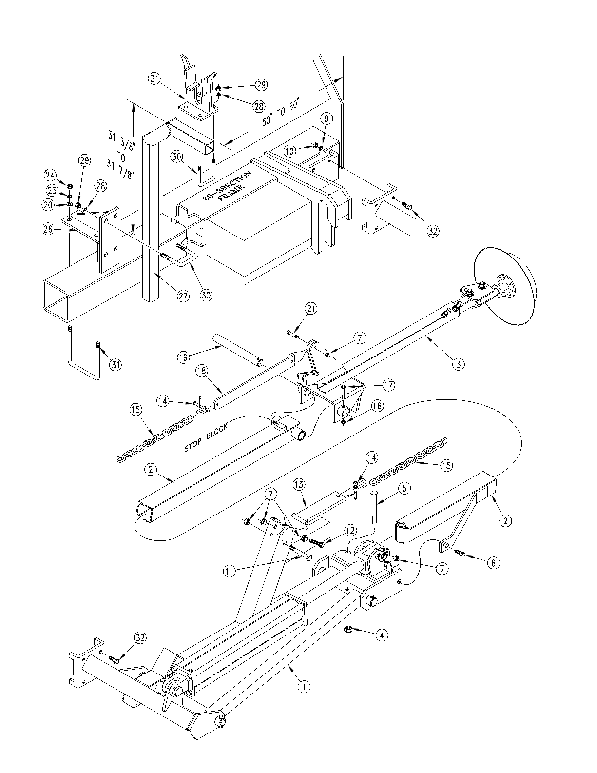
FLAT FOLD MARKER ASSEMBLY INSTRUCTIONS
FOR THE FOLLOWING INSTRUCTIONS, REFER TO THE ILLUSTRATIONS ON PAGE 5:
1. Lower the drill to field position and allow clearance of 16’ on drill for marker assembly from
each end of the box.
2. Attach the marker first section (#1) to the marker bracket at the end of the drill frame using 5/
8” x 2” long bolt (#35), lock washer (#9) and hex nut (#10).
3. Assemble the marker in a horizontal position, remove the port plugs in the hydraulic cylinder
to allow the fold cylinder to be extended. Then fold the first section and the lift lug (#1) to a hor
izontal position.
4. With the stop block position on top of second section (#2) align the holes of the second section
with the holes of the first section (#1)and bolt together with the 5/8” x 5 1/2” long bolt (#5), lock
nut (#4) 3/8” x 2” long shear bolt (#6) and lock nut (#7).
5. Place the third section (#3) over the end of the second section (#2) and insert the hinge pin
(#19) through the second and third section pivot. Secure the hinge pin (#10) with 1/4” x 2” long
bolt (#17) and lock nut (#16).
1-6
-
6. Bolt the chain bar weldment (#13) to the first section (#1) with 3/8” x 3 1/4” long bolt (#11), and
lock nut (#7). The chain bar weldment (#13) should pivot freely on the 3/8” bolt (#11). Bolt the
chain bar (#18) to the third section (#3) with the 3/8” x 1 1/2” long bolt (#21) and lock nut (#7).
The chain bar (#18) should pivot freely on the 3/8” bolt (#21). Connect the marker chain (#15)
between the chain bar (#18) and chain bar weldment (#13) with 5/16” utility clevis (#14). With
the marker disk adjusted for seeding width and disk touching the ground adjust chain length to
remove the slack. Adjustment should be made at the utility clevis (#14) nearest to the drill.
7. The purpose of the 3/8” stop bolt (#12) is to hold tension on the marker chain (#15). ONLY
when the marker is in folding position. Therefore; the 3/8” stop bolt (#12) lock nuts (#7) should
be positioned in the lift arm (#1) so the head of the stop bolt extends as little as possible. After
marker is folded adjust stop bolt to tighten chain.
8. Mount the marker carrier (#27) with the transport arm mount weldment (#26) using 1/2” x 2” x
3” long u-bolts (#30), lock washers (#28), and hex nuts (#29) approximately 50” to 60” from the
outer end of the drill. Clamp the transport arm mount weldment (#23) to the drill frame with 3/8”
x 6” x 6 3/4” long u-bolts (#31) flat washers (#20) lock washers (#32) and hex nuts (#33). The
carrier arm should be set at 31 3/8” high above the drill frame.
9. Mount the support arm saddle (#34) to the support arm (#27) with 1/2” x 2” x 3” long u-bolts
(#30), lock washers (#28) and he x nuts (#29). The support saddle should be centered under the
marker chain and the square tube of the second section (#2) when folded to pre vent wear. The
support arm should support the second section is parallel with the seed box lid. Adjustment can
be made by loosening u-bolts that clamp the marker carrier and slide marker carrier up or down
to parallel marker with drill box lid.
10.Fold the marker to transport position. With the marker chain (#15) in the slot of the support
arm saddle (#34) take up the slack in the marker chain by threading the 3/8” x 2 1/2” long hex
bolt (#13) out against the chain bar weldment (#13) lock this stop bolt in position with the two he x
nuts (#7).
Page 7

1-7
03-01-92
FLAT FOLD MARKER
10106
Page 8

03-01-92
FLAT FOLD MARKER (CON’T.)
Ref. Part No. Description
1. 803-021C Nut, Hex 5/8"-11
2. 804-022C Washer, Lock Spring 5/8"
3. 802-058C Bolt, Hex 5/8"-11 x 2 1/2" Long
4. 113-199H Right Hand Marker Mount
113-179H Left Hand Marker Mount
5. 113-188H Right Hand First Section
113-180H Left Hand First Section
6. 890-005C Bushing, Cylinder 1 1/4" x 1" x 1" Long
7. 800-001C Zerk, Straight 1/4"-28
8. 113-312D First Pivot Shaft
9. 802-168C Bolt, Hex 3/8"-16 x 3 1/4" Long
10. 803-013C Nut, Lock 3/8"-16
11. 113-189H Lift Lug Channel Right Hand
113-181H Lift Lug Channel Left Hand
12. 113-313D Second Pivot Shaft
13. 804-029C Washer, Flat 1"
14. 113-248D Marker Cylinder Pin Body
15. 805-058C Pin, Cotter 3/16" x 2"
16. 802-201C Bolt, Hex Head 1/2"-13 x 4 3/4" Long
17. 803-019C Nut, Lock 1/2"-13
18. 802-066C Bolt, Hex 3/8"-16 x 2" Long Gr 2
19. 113-324D Cylinder Stop
20. 113-325D Stop Bushing
21. 113-190H Right Hand Second Section
113-182H Left Hand Second Section
22. 804-011C Washer, Flat 3/8"
23. 802-022C Bolt, Hex 3/8"-16 x 1 1/2" Long
24. 113-311D Hinge Pin
25. 113-183H Marker Third Section
26. 803-036C Nut, Hex, Jam 1/2"-13
27. 801-054C Screw, Set, Square Head 1/2"-13 x 1"
28. 804-017C Washer, Flat 1/2" USS
29. 113-351D Marker Tube 40 1/2" Long
113-184H 27’ & 30’ Marker Tube Weldment
30. 113-305K Marker Disk, Bearing & Depth Band Assembly
31. 107-111D Bearing Flange Dust Cover
32. 802-059C Bolt, Hex 5/8"-11 x 3" Long
33. 810-118C Cylinder 2 1/2" x 20" x 1 1/4" Rod
34. 113-200H Chain Bar Weldment
35. 802-261C Bolt, Hex 3/8"-16 x 2 1/2" Long
36. 803-148C Nut, Hex Nylock 5/8"-11
37. 802-254C Bolt, Hex 5/8"-11 x 5 1/2" Long
38. 113-319D Marker Chain 71" Long
39. 890-018C Utility Clevis 5/16"
40. 113-323D Chain Bar
41. 113-197D Marker Carrier
42. 113-316H Transport Arm Mount Weldment
43. 113-281H Blade Adjuster Weldment
44. 804-015C Washer, Lock Spring 1/2"
45. 803-020C Nut, Hex 1/2"-13
46. 806-005C U-Bolt, 1/2"-13 x 2" x 3" Long
47. 113-198H Support Arm Saddle
48. 802-152C Bolt, Hex 1/4"-20 x 2" Long
49. 803-007C Nut, Lock 1/4"-20
50. 806-060C U-Bolt, 1/2"-13 x 6 1/32" x 7 1/4" Long
51. 802-041C Bolt, Hex 1/2"-13 x 3 1/2" Long
52. 803-008C Nut, Hex 5/16"-18
53. 804-009C Washer, Lock 5/16"
54. 113-304H Marker Depth Band Weldment
55. 800-010C Rivet, Button Head 3/16" x 9/16" Long
56. 107-110D Ribbed Bearing Flange
57. 188-001V Bearing AA 205 DO
58. 820-083C Marker Disk
59. 113-303S Marker Disk & Bearing Assembly
60. 802-092C Bolt, Carriage 5/16"-18 x 3/4" Long Gr 5
1-8
Page 9

1-9
SINGLE FLAT FOLD MARKER HYDRAULIC ASSEMBLY INSTRUCTIONS
1. Attach fittings (#16) & (#18) to cylinder ports. Attach the needle valve (#14) & (#15) to the
cylinder fittings as show below . Bolt selector v alv e (#11) to the selector valv e mount on T-F rame
with 3/8” x 3” long bolts (#20), flat washers (#21) lock washer (#22) and n ut (#23). Route the hy
draulic hoses (#7) & (#10) from the fold h ydraulic cylinders and marker hydraulic cylinders (hoses
(#14) & (#15)) to the selector valve as sho wn in illustration. Route h ydraulic hoses (#24) & (#25)
from the tractor , through the drill tongue to the selector valv e. Secure the h ydr aulic hoses to the
frame with plastic tie straps (#13) to prevent kinking and pinching during folding operations.
SINGLE MARKER HYDRAULICS
03-01-92
-
10060
Page 10

03-01-92
SINGLE MARKER HYDRAULICS
Ref. Part No. Description
1. 810-065C Cylinder 3 1/2" x 24" x 1 1/2" Rod
2. 811-172C Hydraulic Fitting 1/16" Orifice Plate
3. 811-133C Hydraulic Fitting 3/4" O-RING x 9/16" JICM
4. 811-061C Hydraulic Fitting 6 JIC M x 6 JIC F Tee
5. 811-169C Hydraulic Fitting 3/8" M-F Elbow
6. 811-171C Hydraulic Fitting -8 MORB x -6 JIC M Elbow
7. 811-056C Hydraulic Hose 3/8" x 42 R1
8. 811-307C Hydraulic Hose 1/4" x 108 R1
9. 811-308C Hydraulic Hose 1/4" x 54 R1
10. 811-309C Hydraulic Hose 1/4" x 66 R1
11. 810-023C Double Selector Valve
12. 811-134C Hydraulic Fitting 9/16" JIC x 1/2" MNPT 90
13. 800-082C Cable Tie
14. 811-035C Hydraulic Hose, 1/4" x 21’ Long
15. 811-293C Hydraulic Hose, 1/4" x 272" Long
16. 811-301C Hydraulic Fitting 1/2" MNPT x 3/8"Swivel 90 Degree
17. 810-058C Needle Valve 3/8"
18. 811-044C Hydraulic Fitting 3/8" NPT Close Nipple
19. 810-118C Hydraulic Cylinder 2 1/2" x 20" Stroke
20. 802-024C Bolt, Hex Head 3/8"-16 x 3" Long
21. 804-013C Washer, Lock Spring 3/8"
22. 804-011C Washer, Flat 3/8" USS
23. 803-014C Nut, Hex 3/8"-16
24. 811-306C Hydraulic Hose 1/4" x 360 R1
25. 811-305C Hydraulic Hose 1/4" x 336 R1
26. 810-019C Hydraulic Cylinder 3" x 20" Stroke
27. 811-214C Hydraulic Fitting 1/2" MNPT x 3/8" FNPT 90 Degree Street L
28. 811-213C Hydraulic Fitting 1/2" MNPT x 3/8" MNPT 90 Degree Elbow
1-10
Page 11

1-11
DUAL FLAT FOLD MARKER HYDRAULIC ASSEMBLY INSTRUCTIONS
NOTE: JIC fittings DO NOT require high torque. JIC and O-ring fittings DO NOT require sealant. ALWAYS use
liquid pipe sealant when adding or replacing pipe thread fittings. To avoid possible danger of cracking hydraulic fittings from over tightening, DO NOT use plastic sealant tape.
Refer to figure below and page 13 for the following instructions:
1. Attach the selector / sequence valve to the selector valv e mount the T-Fr ame (#11) using 3/8”
bolts (#20) flat washers (#22) lock washers (#21) and hex nuts (#23).
2. Route hoses from the selector / sequence valve down the drill box frame tube. Check hose
routing for pinching and kinking of hoses and securely attach with plastic cable ties (#13).
3. Attach hoses to cylinder ports. Be certain to double check for correct port location back to the
sequence valve.
4. Detach existing tractor hoses (#18) & (#19) from fold cylinders. Attach 66” hose (#10) and 42”
hose (#7) and tractor hoses (#18) & (#19) to selector / sequence valv e (#11) and wing cylinders.
Assemble remaining hoses as indicated.
03-01-92
IMPORTANT! BEFORE CONTINUING WITH THESE INSTRUCTIONS, READ
“BLEEDING THE HYDRAULICS” INSTRUCTIONS ON
PAGE 4. BLEED ALL
THE AIR OUT OF THE HYDRAULIC SYSTEM BEFORE FOLDING THE
MARKER.
5. Cycle marker as instructed on page 4.
6. When ready to fold wing boxes f or tr ansporting, position the handle on the selector/sequence
valve towards the port marked "G". Hydraulic oil is now diverted to the fold cylinders
NOTE: Raising and low ering speed of the markers is due to the internal orifice in the sequence
valve necessary for proper operation of the valve spool.
DOUBLE SELECTOR VALVE
MOUNT ON T-FRAME
EXCESSIVE SPEED CAN CAUSE MARKER DAMAGE.
!
DO NOT ALLOW ANYONE NEAR THE DRILL WHEN CYCLING THE MARKER!
!
NOTE: To avoid crac king the hydraulic pipe fittings , DO NOT use plastic sealant tape . Use liquid
sealant to seal hydraulic pipe fittings only.
Page 12

03-01-92
1-12
FLAT FOLD
MARKER
TABLE OF CONTENTS
Marker Assembly-------------------------------------------- 1-13
Marker Disk & Bearings ----------------------------------- 1-15
Single Hydraulic Schematic ------------------------------ 1-17
Dual Hydraulic Schematic--------------------------------- 1-19
2 1/2" x 20" Cylinder {810-118C}------------------------ 1-21
Double Selector Valve {810-023C} --------------------- 1-23
Selector / Sequence Valve {810-085C}---------------- 1-25
PARTS BOOK
Page 13

1-13
03-01-92
DUAL MARKER HYDRAULICS
10059
Page 14

03-01-92
DUAL MARKER HYDRAULICS (CON’T)
Ref. Part No. Description
1. 810-065C Cylinder 3 1/2" x 24" x 1 1/2" Rod
2. 811-172C Hydraulic Fitting 1/16" Orifice Plate
3. 811-133C Hydraulic Fitting 3/4" O-RING x 9/16" JICM
4. 811-061C Hydraulic Fitting 6 JIC M x 6 JIC F Tee
5. 811-169C Hydraulic Fitting 3/8" M-F Elbow
6. 811-171C Hydraulic Fitting -8 MORB x -6 JIC M Elbow
7. 811-056C Hydraulic Hose 3/8" x 42 R1
8. 811-307C Hydraulic Hose 1/4" x 108 R1
9. 811-308C Hydraulic Hose 1/4" x 54 R1
10. 811-309C Hydraulic Hose 1/4" x 66 R1
11. 810-085C Selector/Sequence Valve
12. 811-250C Hydraulic Fitting -8 JICF x -6 JICM Elbow (Pre July 1990)
811-319C Hydraulic Fitting -6 JICF x -6 JICM Swivel Elbow
13. 800-082C Cable Tie
14. 811-035C Hydraulic Hose, 1/4" x 21’ Long
15. 811-293C Hydraulic Hose, 1/4" x 272" Long
16. 811-281C Hydraulic Fitting 3/8" FNPT Swivel x 9/16" MORB
17. 810-118C Hydraulic Cylinder 2 1/2" x 20" Stroke
18. 811-306C Hydraulic Hose 1/4" x 360 R1
19. 811-305C Hydraulic Hose 1/4" x 336 R1
20. 802-024C Bolt, Hex Head 3/8"-16 x 3" Long
21. 804-013C Washer, Lock Spring 3/8"
22. 804-011C Washer, Flat 3/8" USS
23. 803-014C Nut, Hex 3/8"-16
24. 810-019C Hydraulic Cylinder 3" x 20" Stroke
25. 811-301C Hydraulic Fitting 1/2" MNPT x 3/8" FNPT 90 Degree Swivel
1-14
SERVICE
Keep marker adequately lubricated. Use a heavy duty multipurpose grease for lubrication.
Recommended Greasing - every 20 - 25 Hours.
Lubrication Points:
2 - Zerks on right and left hand first section (#5)
Page 15

03-01-92
1-18
WARRANTY
Great Plains warrants to the original purchaser of new Great Plains
Products, that they are free of defects in material and workmanship.
This warranty is applicable only for the normal life expectancy of the
unit or individual components for a period of one year from date of
original purchase if for personal use; 90 days for commercial or rental
purposes. Warranty coverage is limited to replacing any part, at no
charge to the original purchaser, that in our judgment shows
evidence of a defect: provided that upon written request, any such
defective part is returned to Great Plains within (30) days of failure.
This Warranty does not apply to any part or product which in Great
Plains’s judgment shall have been misused or damaged by accident
or lack of normal maintenance or care, or which has been repaired or
altered in a way which adversely affects its performance or reliability,
or which has been used for a purpose for which the product is not
designed.
Claims under this Warranty must be made to the dealer which
originally sold the product. Great Plains reserves the right to make
changes in materials or design of the product at any time without
notice.
This Warranty shall not be interpreted to render Great Plains
liable for damages of any kind, direct, consequential, or
contingent, to property. Furthermore, Great Plains shall not be
liable for damages resulting from any cause beyond its
reasonable control. This Warranty does not extend to any
expense due to loss for labor, supplies, rental machinery or for
any other reason.
No other Warranty of any kind whatsoever, express or implied, is
made with respect to this sale; and all implied warranties of
merchantability and fitness for a particular purpose which exceed the
obligations set forth in this written warranty are hereby disclaimed
and excluded from this sale.
 Loading...