

Page 1
Operator’ s Manual
Three-Point Soybean Machine
Model Serial No.
2015 1152M+
Manufacturing, Inc.
www .g reatplainsmfg.com
Read the operator’s manual entirely. When you see this symbol, the subsequent in-
!
structions and warnings are serious -follow without exception. Your life and thelivesof
others depend on it!
2015
© Copyright 1997 Printed
4/18/2005
13402
Cover illustration may show optional equipment not supplied with standard unit.
173-088M
Page 2

General Information
General Information
Important Notice
Great Plains Manufacturing, Inc. provides this publication “as is” without warranty of any kind, either
expressed or implied, while every precaution has been
taken in the preparation of this manual, Great Plains
Manufacturing,Inc. assumes no responsibility for errors
oromissions.Neither is any liability assumed for damages resulting from the use of the information contained
herein. Great Plains Manufacturing, Inc. reserves the
righttoreviseand improveitsproductsasitseesfit.This
This Operators Manualapplies tothe 20’3-PointSoy-
bean Machine
Owner’s Information
publicationdescribesthe state of this product atthetime
of its publication, and may not reflect the product at all
times in the future.
Printed in the United States of America.
For your convenience, record your Serial Number,Mod-
el Number and the Date Purchased in the spaces
provided below. Have this information before you when
calling a Great Plains Authorized Dealer.
Name: _____________________________________
Address ____________________________________
City________________State ____ Zip
Phone_______________________
Name of Dealership ___________________________
Dealer’s Name _______________________________
Address ____________________________________
City________________State ____ Zip
Phone_______________________
Serial Number ________________
Model Number________________
Date Purchased_______________
2015 Three-Point Soybean Machine 173-088M 4/18/05Great Plains Mfg., Inc.
Page 3

Table of Contents
Table of Contents
Using this Manual . . . . . . . . . . . . . . . . . . . . . . . . . . 2
Introduction . . . . . . . . . . . . . . . . . . . . . . . . . . . . . . . 2
Section 1 Safety Rules . . . . . . . . . . . . . . . . . . . . . . 3
General Operation & Repair . . . . . . . . . . . . . . . . 3
Transporting . . . . . . . . . . . . . . . . . . . . . . . . . . . . 3
Tire Handling & Repair . . . . . . . . . . . . . . . . . . . . 3
Safety Decals . . . . . . . . . . . . . . . . . . . . . . . . . . . 3
Section 2 Assembly Instructions & Set-Up . . . . . . 6
Torque Values Chart. . . . . . . . . . . . . . . . . . . . . . . 6
Tire Inflation Chart . . . . . . . . . . . . . . . . . . . . . . . . 6
Left Hand Gauge Wheel . . . . . . . . . . . . . . . . . . . 7
Right Hand Gauge Wheel . . . . . . . . . . . . . . . . . . 8
Drive Installation. . . . . . . . . . . . . . . . . . . . . . . . . . 8
Tractor Requirements. . . . . . . . . . . . . . . . . . . . . . 9
Section 3 Basic Operation . . . . . . . . . . . . . . . . . . . 11
Drill Preparation And Field Operations. . . . . . . . 11
Transporting . . . . . . . . . . . . . . . . . . . . . . . . . . . . 11
Parking. . . . . . . . . . . . . . . . . . . . . . . . . . . . . . . . 11
Section 4 Adjustments. . . . . . . . . . . . . . . . . . . . . . 13
Gauge Wheel Adjustments. . . . . . . . . . . . . . . . . 13
Opener Down Force. . . . . . . . . . . . . . . . . . . . . . 13
Row Unit Mounted Coulter . . . . . . . . . . . . . . . . . 14
Depth Adjustment. . . . . . . . . . . . . . . . . . . . . . . . 14
1" x 12" Closing Wheel Adjustments . . . . . . . . . 14
Closing Disk Adjustments. . . . . . . . . . . . . . . . . . 15
Seed Lok . . . . . . . . . . . . . . . . . . . . . . . . . . . . . . 16
Seed Rate . . . . . . . . . . . . . . . . . . . . . . . . . . . . . 16
Seed Rate Chart. . . . . . . . . . . . . . . . . . . . . . . . . 17
Marker Adjustments . . . . . . . . . . . . . . . . . . . . . . 18
Section 5 Maintenance & Lubrication. . . . . . . . . . 20
Maintenance. . . . . . . . . . . . . . . . . . . . . . . . . . . . 20
Storage. . . . . . . . . . . . . . . . . . . . . . . . . . . . . . . . 20
Lubrication . . . . . . . . . . . . . . . . . . . . . . . . . . . . . 20
Section 6 Troubleshooting. . . . . . . . . . . . . . . . . . . 24
Section 7 Specifications. . . . . . . . . . . . . . . . . . . . . 26
Warranty. . . . . . . . . . . . . . . . . . . . . . . . . . . . . . . 27
4/18/05 Great Plains Mfg., Inc.
2015 Three-Point Soybean Machine 173-088M
-1
Page 4
Using this Manual
Using this Manual
For your safety and to help in developinga better understanding of your equipment we highly recommend that
you read the operator sections of this manual. Reading
these sections not only provides valuable training but
also familiarizes you with helpful information and its lo-
Introduction
This manual has been prepared to instruct you in the
safeand efficient operation of your 20’ 3-PointSoybean
Machine.Readand followall instructionsand safety precautions carefully.
Read and follow all instructions and safety precautions
carefully.
Theparts on yourdrillhavebeen speciallydesignedand
shouldonly be replacedwithgenuine GreatPlainsparts.
Therefore,shouldyour drill requirereplacementpartsgo
to your Great Plains Dealer.
The right hand and left hand as used throughout this
manual is determined by facing in the direction the drill
will travel when in use unless otherwise stated.
Serial Number
Theserialnumberplateislocated on the frontsideofthe
main frame tube, to the left of the 3-point hitch plate. It is
suggested that the serial number and purchase date
also be recorded for your convenience in the space provided on the checklist page at the beginning of this
manual.
Theserial number provides importantinformation about
your drill and may be required to obtain the correct replacement part. Always use the serial number and
model number when sending correspondence or when
ordering parts from your Great Plains Dealer.
cation. The parts sections are for reference only and
don’trequire covertocoverreading.Afterreviewingyour
manual store it in a dry,easily accessible location for future reference.
potential hazard to personal safety involved and extra
safety precautions must be taken. When you see this
symbol, be alertand carefully read themessage that follows it. In addition to design and configuration of
equipment; hazard control and accident prevention are
dependentupon the awareness,concern,prudence and
proper training of personnel involved in the operation,
transport, maintenance and storage of equipment.
Watchforthe followingsafety notations through-out
your Operators Manual:
!
DANGER!
Indicates an imminently hazardous situation which, if
not avoided, will result in death or serious injury. This
signal word is limited to the most extreme situations.
!
WARNING!
Indicates a potentially hazardoussituation which, if not
avoided, could result in death or serious injury.
!
Indicates a potentially hazardoussituation which, if not
avoided, may result in minor or moderate injury.It may
also be used to alert against unsafe practices.
CAUTION!
!
NOTE: Indicates a special point of information which
The SAFETY ALERT SYMBOL indicates that there is a
2
2015 Three-Point Soybean Machine 173-088M 4/18/05
requires your attention.
Great Plains Mfg., Inc.
Page 5

Section 1 Safety Rules
Section 1 Safety Rules
Most accidents are the result of negligence and carelessness, usually caused by failure of the operator to
follow simple but necessary safety precautions. The followingsafetyprecautions are suggested to help prevent
such accidents. The safeoperation of any machinery is
abigconcern to consumers and manufacturers.Your20’
3-PointSoybeanMachine has been designedwithmany
built-insafetyfeatures.However, no one should operate
this product before carefully reading this Operators
Manual.
!
General Operation & Repair
1. Never allow the 20’ 3-Point Bean Machine to be operated by anyone who is unfamiliar with the operation of all
functions of the drill. All operators should read and thoroughly understand the instructions given in this manual
prior to moving the drill.
2. Make sure safety rules are understood before operating
machinery or tractor.
3. Never permit any persons other than the operator to ride
on the tractor.
4. Never permit any persons to ride on or stand near the
drill while it is in operation.
5. Regulate your speed to the field conditions, maintaining
complete control at all times.
6. After repairing or adjusting, make sure all tools and
parts are removed from the implement before attempting
to operate it.
7. Do not grease or oil machine while it is in operation.
8. Loose fitting clothing should not be worn as it may catch
in moving parts.
9. Never dismount from a moving tractor.
10. Do not leave the tractor or the implement unattended
with the engine running.
11. Do not stand between the tractor and the implement during hitching.
12. Detach and store implements in an area where children
normally do not play. Stabilize implements by using suitable supports and block wheels.
13. If a hydraulic leak develops, correct it immediately. Escaping hydraulic oil can have extremely high pressure. A
stream of high pressure oil may easily penetrate the skin
as with modern needle-less vaccination equipment - but
with the exception that hydraulic fluid may cause blood
poisoning. It is imperative that the connections are tight
and that all lines and pipes are in good condition. If an
injury is caused by the escaping hydraulic fluid, see doctor at once!
14. Use a piece of cardboard or wood to detect leaks of hydraulic oil under pressure.
15. Be sure to relieve all hydraulic pressure before disconnection any lines or pipes between the implement and the tractor hydraulic system. Keep all guards and shields inplace.
Transporting
1. Use good judgement when transporting tractor and implements on the highway. Always maintain complete control of the drill.
2. Limit transport speed to 20 mph. Transport only with a
farm tractor of sufficient size and horse power.
3. Always make sure flashing safety lights, “Slow Moving
Vehicle” emblem, and reflectors are in place and visible
prior to transporting the drill on public roads.
4. Know your state and local laws concerning highway
safety and regulations. Comply with these laws when
transporting machinery.
5. Use warning flags or approved warning lights at night
and during other periods of poor visibility. Do your best
to prevent highway accidents.
Tire Handling & Repair
1. Tire changing can be dangerous and should be preformed by trained personnel using the correct tools and
equipment.
2. Do not re-inflate a tire that has been run flat or seriously
under inflated. Have it checked by qualified personnel.
3. When removing and installing wheels, use wheel handling equipment adequate for the weight involved.
Safety Decals
1. Your 20’ 3-Point Soybean Machine comes equipped with
all safety decals in place. They were designed to help you
safely operate your 20’ 3-Point Bean Machine. Read and
follow their directions.
2. Keep safety decals clean and legible.
3. Replace all damaged or missing safety decals. To order
newsafety decals goto your Great Plains Dealerand refer
to the parts section for safety decal package part number.
4. Replace these decals whenever they become worn or unreadable. To instal new safety decals:
a. Clean the area the decal is to be placed
b. Peel backing from the decal. Press firmly on to sur-
face being careful not to cause air bubbles under the
decal.
4/18/05 Great Plains Mfg., Inc.
2015 Three-Point Soybean Machine 173-088M
-3
Page 6
Section 1 Safety Rules
13500
13500
818-188C
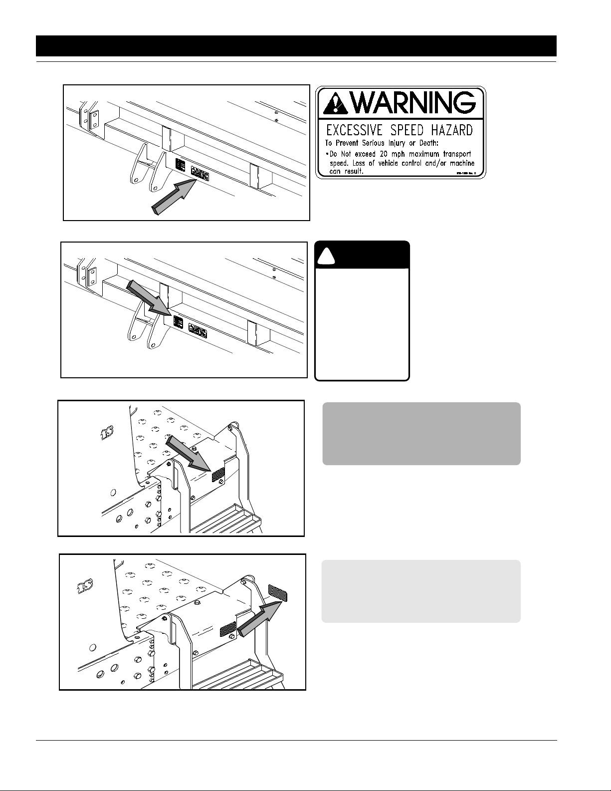
Transport Speed Warning
CAUTION
!
Read Owner’s Manual Before
Operating Drill
Stand Clear When Raising and
Lowering Drill
Keep Hands and Clothing Away
From Moving Chains and
Sprockets
Never Ride On Drill
Never Stand Between Tractor
Tire and DrillWhen Raising and
Lowering Drill
818-005C
818-005C
General Caution
838-266C
Amber Reflector
13501
838-265C
Red Reflectors
13501
4
2015 Three-Point Soybean Machine 173-088M 4/18/05
Great Plains Mfg., Inc.
Page 7
Section 1 Safety Rules
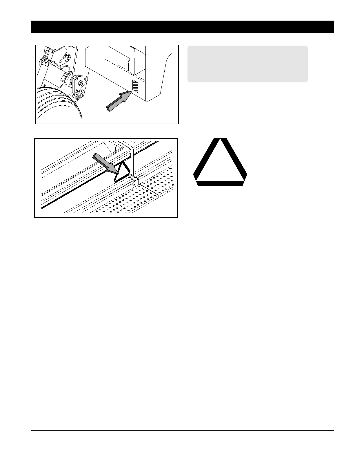
13502
838-265C
Amber Reflectors
13499
818-003C
Slow Moving VehicleEmblem
4/18/05 Great Plains Mfg., Inc.
2015 Three-Point Soybean Machine 173-088M
-5
Page 8
Section 2 Assembly Instructions & Set-Up
Section 2 Assembly Instructions & Set-Up
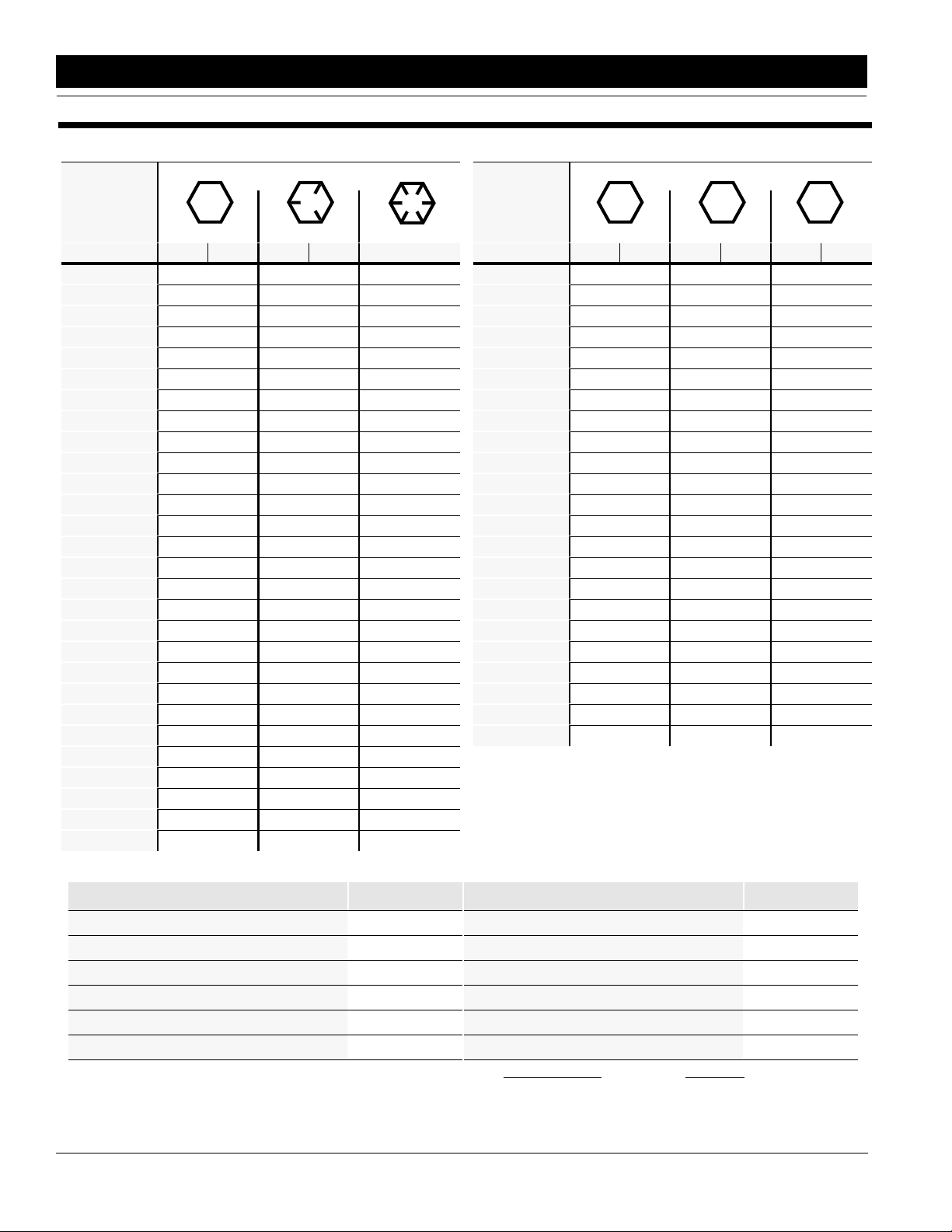
Torque Values Chart for Common Bolt Sizes
Bolt Head Identification
Bolt Head Identification
Bolt Size
(Inches)
1
in-tpi
1/4" - 20 7.4 5.6 11 8 16 12 M 5 X 0.8 436597
1/4" - 28 8.5 6 13 10 18 14 M 6 X 1 7 5 11 8 15 11
5/16 - 18 15 11 24 17 33 25 M 8 X 1.25 17 12 26 19 36 27
5/16" - 24 17 13 26 19 37 27 M 8 X 1 18 13 28 21 39 29
3/8" - 16 27 20 42 31 59 44 M10 X 1.5 33 24 52 39 72 53
3/8" - 24 31 22 47 35 67 49 M10 X 0.75 39 29 61 45 85 62
7/16" - 14 43 32 67 49 95 70 M12 X 1.75 58 42 91 67 125 93
7/16" - 20 49 36 75 55 105 78 M12 X 1.5 60 44 95 70 130 97
1/2" - 13 66 49 105 76 145 105 M12 X 1 90 66 105 77 145 105
1/2" - 20 75 55 115 85 165 120 M14 X 2 92 68 145 105 200 150
9/16" - 12 95 70 150 110 210 155 M14 X 1.5 99 73 155 115 215 160
9/16" - 18 105 79 165 120 235 170 M16 X 2 145 105 225 165 315 230
5/8" - 11 130 97 205 150 285 210 M16 X 1.5 155 115 240 180 335 245
5/8" - 18 150 110 230 170 325 240 M18 X 2.5 195 145 310 230 405 300
3/4" - 10 235 170 360 265 510 375 M18 X 1.5 220 165 350 260 485 355
3/4" - 16 260 190 405 295 570 420 M20 X 2.5 280 205 440 325 610 450
7/8" - 9 225 165 585 430 820 605 M20 X 1.5 310 230 650 480 900 665
7/8" - 14 250 185 640 475 905 670 M24 X 3 480 355 760 560 1050 780
1" - 8 340 250 875 645 1230 910 M24 X 2 525 390 830 610 1150 845
1" - 12 370 275 955 705 1350 995 M30 X 3.5 960 705 1510 1120 2100 1550
1-1/8" - 7 480 355 1080 795 1750 1290 M30 X 2 1060 785 1680 1240 2320 1710
1 1/8" - 12 540 395 1210 890 1960 1440 M36 X 3.5 1730 1270 2650 1950 3660 2700
1 1/4" - 7 680 500 1520 1120 2460 1820 M36 X 2 1880 1380 2960 2190 4100 3220
1 1/4" - 12 750 555 1680 1240 2730 2010
1 3/8" - 6 890 655 1990 1470 3230 2380
1 3/8" - 12 1010 745 2270 1670 3680 2710
1 1/2" - 6 1180 870 2640 1950 4290 3160
1 1/2" - 12 1330 980 2970 2190 4820 3560
Grade 2 Grade 5
N · m2ft-lb3N · m ft-lb N · m ft-lb mm x pitch
Grade 8
Bolt Size
(Metric)
4
1
in-tpi = nominal thread dia.in inches-threads per inch
2
N· m = newton-meters
3
ft-lb= foot pounds
4
mm x pitch = nominal thread dia. in millimeters x thread pitch
5.8 8.8 10.9
Class 5.8 Class 8.8 Class 10.9
N · m ft-lb N · m ft-lb N · m ft-lb
Tire Inflation Chart
Tire Size Inflation PSI
7.50 x 20" 4-Ply Drill Rib 28
9.0 x 22.5 10-Ply Highway Service 70 70
9.0 x 24" 8-Ply Rib Implement 40
9.5L x 15" 6-Ply Rib Implement 32
9.5L x 15" 8-Ply Rib Implement 44
9.5L x 15" 12-Ply Rib Implement 60
NOTE:All tires are warranted by the original manufacturer of the
tire. Tire warranty information can be found in the brochures included with your Operator’s and Parts Manuals or online at the
manufacturer’s websites. For service assistance or information,
contact your nearest Authorized Farm Tire Retailer.
6
2015 Three-Point Soybean Machine 173-088M 4/18/05
Tire Size Inflation PSI
11L x 15" 6-Ply Rib Implement 28
11L x 15" 12-Ply Rib Implement 52
12.5L x 15" 8-Ply Rib Implement 36
12.5L x 15" 10-Ply Rib Implement 44
16.5L x 16.1" 10-Ply Rib Implement 36
41 x 15" x 18 - 22-Ply Rib Implement 44
Manufacturer Website
Titan www.titan-intl.com
Goodyear www.goodyearag.com
Firestone www.firestoneag.com
Great Plains Mfg., Inc.
Page 9
Section 2 Assembly Instructions & Set-Up
The following information is general in nature and was
written to aid the operator in preparation of the tractor
and drill for use, and to provide general operating proce-
dures. The operator’s experience, familiarity with the
drill, and the following information combined should pro-
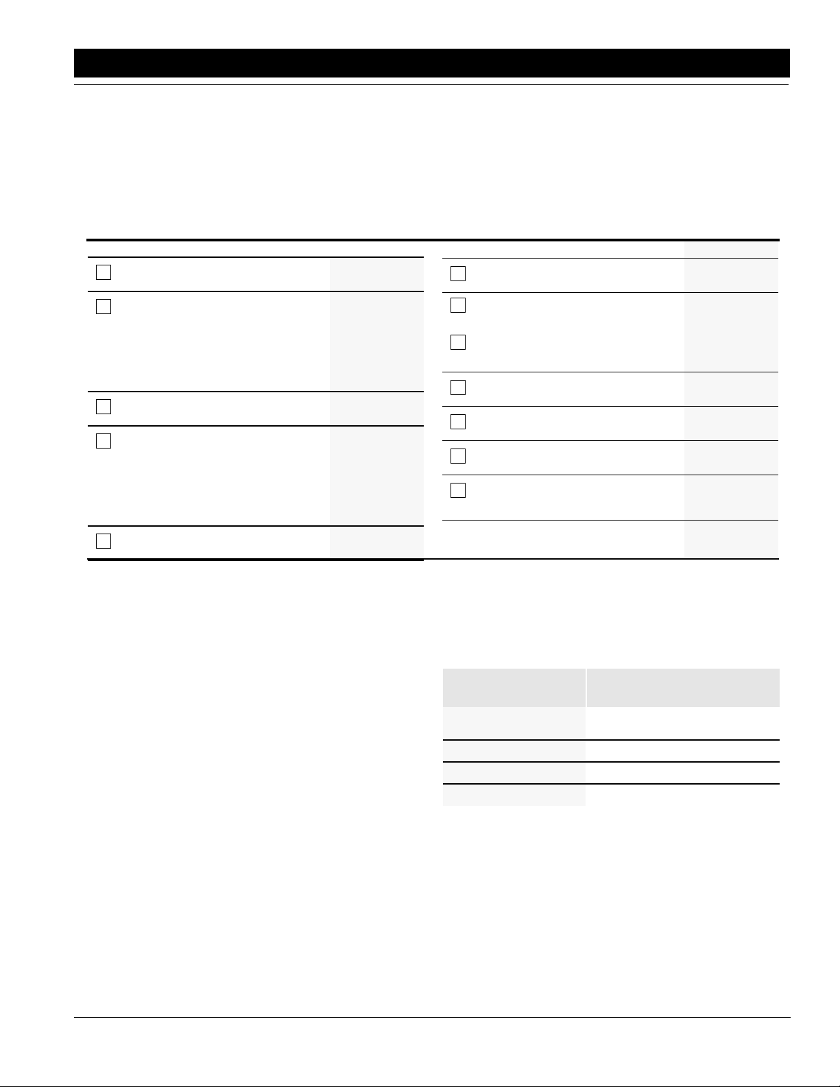
Pre-Assembly Checklist
Check Reference
All major frame components Section 2
Fasteners and pins that were shipped
with the drill.
NOTE: All hardware from the factory has
been installed in the location where it will
be used. If a part or fastener is temporarily removed for assembly reasons,
remember where it goes.Keep the parts
separated.
All working parts are moving freely, bolts
are tight and cotter pins are spread.
If a pin, bolt or other part has been
removed, and you are unsure where it is
used, use the parts section of this manual to identify it. Be sure the part gets
used in the correct location. By double
checking while you assemble, you will
lessen the chance of using a bolt incorrectly that may be needed later.
All grease fittings are in place and lubricated.
Page 7
Operator’s
Manual
Operator’s
Manual
Operator’s
Manual
Section 7
Page 19
vide efficient drill operation and good working habits.
Having all the parts and equipment readily at hand will
speed up your assembly task and make the job as safe
as possible.
Check Reference
Proper tension and alignment on all drive
chains.
Safety decals are correctly located and
legible. Replace if damaged.
Red and amber reflectors are correctly
located and visiblewhen the drill is in the
transport position.
“Slow moving vehicle" emblem is in
place.
Inflate tires to specified air pressure.
Tighten wheel bolts to specified torque.
Havea minimum of 2 people at hand while
assembling the drill.
Have a fork lift or loader along with
chains and safety stands that are sized
for the job ready for the assembly task.
Operator’s
Manual
Section 1
Page 4
Section 1
Page 4
Section 1
Page 5
Section 2
page 6
Section 1
Page 3
Operator’s
Manual
Assembling The Drill
Read and understand the previous section
BEFORE YOU START.
If the gauge wheels are already installed, skip the re-
mainder of this section.
If the drill is shipped without the front gauge wheels,
temporaryblockingwillberequiredunder the frontofthe
drill to keepit from tipping forward.Keep this blockingin
place to hold the drill if you are installing the gauge
wheels.
Left Hand Gauge Wheel
Refer to Figure 2-1:
The left hand gauge wheel (#1) is identified by referring
toFigure 2-1, page 8. Note theextendedwing on thetop
side of the gauge wheel mount where the hex bore jack-
shaft bearing (#2) Figure 2-2 is mounted. This wing
goes towards the outside of the drill.
Based on your application refer to the Gauge Wheel
Placement Chart, under dimension "A". Using this dimension, make a mark on the main frame with a pencil
where your gauge wheel should be mounted.
Gauge Wheel Placement Chart
Description Refer to Dimension "A"
Figure 2-1 Page 8
Standard Installation:
15 Rows at 15"
12 Rows 4-4-4 Skip 30 20 3/16"
12 Rows 4-4-4 Skip 32 18 3/16"
14 Rows 5-4-5 Skip 32 18 3/16"
21 5/16"
Using mechanical assistance, lift the gauge wheel assembly and place it on the frame. Install the two U-bolts
from the back side of the frame tube and through the
mounting holes. Secure with lock washers and nuts.
4/18/05 Great Plains Mfg., Inc.
2015 Three-Point Soybean Machine 173-088M
-7
Page 10

Section 2 Assembly Instructions & Set-Up
13504
Gauge Wheel Mount On To Frame
Figure 2-1
Right Hand Gauge Wheel
Refer to Figure 2-1:
Therighthand(#3)gaugewheelis installed the sameas
the left hand (#1) detailed in under "Left Hand Gauge
Wheel" page 7. Take this same dimension from the other end and mark where the right hand (#3) gauge wheel
should be located.
Drive installation
Refer to Figure 2-2:
1. Locate the 7/8” hex jack shaft (#1).
IMPORTANT:The following shaft installation procedure
will minimize damaging preloading of the sprocket and
bearing assembly (#2).
2. Starting at the gauge wheel, slide the shaft through
the 12 tooth sprocket and bearing assembly (#2). If
the shaft naturally aligns itself withthe 7/8” hex bore
bearing (#3), the sprocket and bearing assemblies
are properly in place.
ingmountedonthe drill frame. The shaft must be level up
and down, and straightfront to back. Tighten both sets of
bearing bolts.
Refer to Figure 2-3
a. Slide the 7/8” hex shaft (#1) backout enough to
slip on the 12 tooth sprocket (#2) if it is not already in place.
IMPORTANT: If the shaft is too high or to low to enter
bearing (#3), loosen the flangette bolts and slide bearing
(#3) up or down until the height matches the shaft. If the
shaft is too far forward or backwardto enter bearing (#3).
Slide the sprocket & bearing assembly (#2) in its mounting holes on the gauge wheel mount extended wing as
needed until the 7/8” hex shaft easily slips into the bear-
8
2015 Three-Point Soybean Machine 173-088M 4/18/05
Drive Shaft Installation
Figure 2-2
Great Plains Mfg., Inc.
13505
Page 11

Section 2 Assembly Instructions & Set-Up
13506
Assembly Illustration
Figure 2-3
b. Slide the 7/8” hex shaft back through the bear-
ing mounted on the drill frame (#3). The shaft is
trapped in place by driving roll pins (#4) on either side of the bearing.
c. Align the 12 tooth sprocket (#2) with the sprock-
etonthefeedcupshaft.Lockthesprocketin position using the sprocket’s set screws.
d. Install the roller chain (#5) using the Routing
Guideabove. Remove excess slackinthechain
with the adjustable idler sprocket (#6).
4/18/05 Great Plains Mfg., Inc.
Routing Guide
The right hand drive on 20’ models is installed by repeating Steps 2. a. through 2. d.
Rotate each gauge wheel tire several turns while
observingtheoperationof the entire drive system. If
any chains bind or pop, re-align those sprockets until the drive system turns smoothly.
3. Recheck all fasteners to see if they are tight, and
that all clips and retainers have snapped into place.
2015 Three-Point Soybean Machine 173-088M
13633
-9
Page 12

Section 2 Assembly Instructions & Set-Up
Tractor Requirements
Great Plains 3-Point Drills are engineered to be used
with Category II, Category III Narrow, or Category III
Wide tractors. 20' 3-Point Drills are factory set for CategoryII tractors. To change toCategory III, exchange the
left hand pin support with the right hand as shown in Figure 2-4.
In addition, the following bushings (not supplied by
Great Plains) may be needed to fit your quick hitch or
tractor’s 3-point arms:
Upper link 1”ID x 1 1/4” OD x 2 1/8” max. long
Lower links 1 1/8” ID x 1 7/16” OD x 2 1/4” max. long
12148
Category II (Factory Set) Hitch
Figure 2-4
12150
Category III Hitch
Figure 2-5
Be sure that all tractor 3-point arms are securely pinned
before lifting the drill. Adjust the top 3-point link so that
the top edge of the box is parallel with the ground. DO
NOT use the link to adjust the depth of opener penetration. Three hitch pins are furnished with each 3-point
Drill.Set your tractor 3-point draft control in the float
position.
.
10
2015 Three-Point Soybean Machine 173-088M 4/18/05
Great Plains Mfg., Inc.
Page 13

Section 3 Basic Operation
Section 3 Basic Operation
Drill Preparation
And Field Operations
1. Becertainthat your rib implement tires are11Lx15"
for the 20' drills. Also check for proper inflation as
listed in “Tire Inflation Chart”, Section 2, page 6.
2. Load seed box withbeans. You should use cleaned
beans to get the best results. You should always
have the drill hitched securely to a tractor and lowered before loading.
3. Your drill comes equipped with an acremeter and it
should be mounted on the outside of the left gauge
wheel jackshaft. It will accumulate the total acres
drilledwiththedrill.In order to find out the acres covered,writedown the beginning reading and subtract
it from the ending readingfor the total acres planted.
4. Make sure that the feed cup door adjustment handle,isinthesecond handle position and is the same
on each cup across the drill.
5. If you notice excessive cracking on large beans, adjust all feed cup door handles to the third position.
6. Never back up with openers in ground. If you do,
check all openers to be sure none are clogged.
7. This drill is not designed to be turned sharply in the
field. Always lift thedrill out of the ground when turningatendsoffieldrowsandother short-radius turns.
8. Never allow anyone to ride on the drill.
9. Maximum seeding speed should vary according to
soil conditions.
•Check to see that the transport tires on the hitch have
the proper inflation as listed in the "Tire Inflation
Chart" Section 2, page 6.
•Comply with all Federal, State and Local Safety Laws
when traveling on public roads.
•Remember, the drill is wider than the tractor and ex-
treme care must be taken to allow for safe clearance.
Parking
Unhitching
The following steps should be done when preparing to
store the drill or unhitch it from the tractor. See also
“Storage”, Section 7, page 19, for additional information on the long term storage of your drill.
1. It is best not to unhitch the drill from the tractor with
a full seed box. Empty the drill if possible.
2. Select a parking spot for the drill on a level, solid area.
3. Unpin and rotate the optionalfront stands down into
position. Replace pins as shown in Figure 3-1.
4. Iftheground is soft, place a board or plate under the
stand to increase the ground contact area.
5. Lower the 3-Point hitch until the drill is on the
ground.
6. Extend or retract the top link of the tractor until the
top 3-point pin is free. Remove the pin. Next, remove the pins from the lower links.
Transporting
!
This drill should never be pulled faster than 20 miles
per hour
Before transporting the drill, follow and check the following items
CAUTION!
!
•This drill can be transported with a full box ofbeans. It
is best NOT to do this unless necessary because the
increased weight does increase the chances for problems on the road. Do not exceed 20 miles per hour.
NOTE: In order to maintain steering control, ballast
may have to be added to tractor front end. To determine the amount of ballast required refer to yourtractor’s operator manual.
•If drill is used with an optional hitch, make sure that
hitchissecurelyattached to the draw bar of the tractor
and that the hitch safety chain has been securely attached.
4/18/05 Great Plains Mfg., Inc.
13508
Optional Parking Stand
Figure 3-1
2015 Three-Point Soybean Machine 173-088M
-11
Page 14

Section 3 Basic Operation
Hitching:
The following steps should be done when preparing to
hitch the drill to the tractor.
1. Raise or lower 3-Point arms on the tractor as needed and install the lower hitch pins. Pin the top 3Point link to the drill. Category II in the lower hole,
Category III in the upper hole.
2. Slowly raise the drill! Watch for cab interference!
NOTE: Do not stand between the tractor and the implement during hitching.
3. Unpin the stand tubes. Rotate up into storage position and repin.
12
2015 Three-Point Soybean Machine 173-088M 4/18/05
Great Plains Mfg., Inc.
Page 15

Section 4 Adjustments
Section 4 Adjustments
Gauge Wheel Adjustments
The planter rows on the drill are adjusted by raising or
lowering the gauge wheels.
Raise the drill out of the ground and loosen the jam nut
located near the bottom clevis of the gauge wheel turnbuckle,Figure 4-1. This turnbuckle is threaded to
alloweasy gauge wheel adjustment. By lengthening the
Opener Down Force
Standard Spring Package
The standard down force spring package, consists of 2
non-adjustable springs applying approximately
90 lbs. of down force.
Optional Medium and Heavy Duty Spring Package
The medium and heavy duty spring packages consist of
2or 4 adjustablesprings,respectively. The mediumduty
packagecanbe adjusted from approximately 100 to 200
lbs. down force. The heavy duty package can be adjusted from approximately 200 to 400 lbs. of down force.
Spring Adjustments
• All spring adjustments must be made with the drill in
the fully raised position.
• The spring package is adjustable from 90 lbs. to 325
lbs. of down force when the parallel arms are horizontal. Consult the "Down Force Pressure Chart".
NOTE: The maximum down force stated before is
reached when the parallel arms are all the way up. To
adjust the spring tension, lift the plunger by pulling up
onthe roll pin handleandsliding the handle adjustment
assembly into the appropriate hole, see Figure 4-2.
12068
Gauge Wheel Turnbuckle
Figure 4-1
turnbucklethe gaugewheelis lowered,alsolowering the
openers. By shortening the turnbuckle the gauge wheel
is raised, also raising the openers. After adjusting, be
sure the turnbuckle on both gauge wheel arms havethe
same pin center dimensions.
Your 3-Point Drill is designed to run level to the ground
when in planting position. Minor adjustments may be requiredtoachieve the desired bean placement. After any
gauge wheel adjustments have been made, use the top
link to set box and frame level to the ground.
• Two springs can be purchased at your Great Plains
Dealerto make the mediumdutypackage into a heavy
duty package or two springs can be removed fromthe
heavydutypackage to make a medium duty package.
Add or subtract springs by removing the snap ring at
the end of the spring pivot rod. Slide the rod inward to
addorremoveaspringfromeachside.Thenattachor
remove the other spring end on the hex bar support.
Reinstall the spring rod and snap ring on each side.
4/18/05 Great Plains Mfg., Inc.
2015 Three-Point Soybean Machine 173-088M
-13
Page 16

Section 4 Adjustments
Down Force Pressure Chart
To Obtain This
* Down Force
90 lbs. 2 A
105 lbs. 2 B
125 lbs. 2 C
140 lbs. 2 D
160 lbs. 2 E
185 lbs. 4 A
215 lbs. 4 B
245 lbs. 4 C
285 lbs. 4 D
325 lbs. 4 E
* Force when arms are parallel.
Use This # of
Springs
In This
Hole
12208
Row Unit Mounted Coulter
Figure 4-3
Depth Adjustment
Theseedingdepth of the row unit is controlled by 2 walking gauge wheels located next to the disks.
Adjust the planting depth as follows:
1. Raise the drill to remove weight from the gauge
wheel.
2. RaisetheT-handleand move it forward to decrease
the seeding depth, see Figure 4-4. Moving the handle rearward increases the seeding depth. Small increments of depth adjustment can be made by
walking the T-handle from side to side.
3. After one row is set to the desired depth, move the
T-handle on the other rows to the same location.
12137
Adjustment Bar
Figure 4-2
Row Unit Mounted Coulter
The optional coulter allows the drill to penetrate tough
groundconditions.Itisrecommendedthat either the medium duty or heavy duty spring package be used in
conduction with this coulter.
Coulter Adjustments
1. To adjust the coulter vertically, loosen the 3/4" jam
nut and the 3/4" x 3" long hex bolt, see Figure 4-3.
2. Byturning the cam hex, rotatethecamcasting to set
the desired height. Forwavy coulter blades, it is recommended that the coulter blade should be run
even to 1" below the disks on the row unit.
3. Tighten the bolt and jam nut to torque values in
"Section 2 Torque Value Chart" on page 6.
14
2015 Three-Point Soybean Machine 173-088M 4/18/05
12345
T-Handle Adjustment
Figure 4-4
1" x 12" Closing Wheel Adjustments
The 1" X 12" closing wheel option can be adjusted for
down force, alignment, and offset.
Great Plains Mfg., Inc.
Page 17

Section 4 Adjustments
Closing Wheel Down Force Adjustment
Adjust the closing wheel down force to permit proper
closingof the seedtrench.It is recommendedtostart with
the T-handle in the first of 4 notches, see Figure 4-5.
If the seed trench is not closing move the handle to the
next notch back and try again. Keep moving the handle
back until the seed trench is closing, by doing this eliminates unnecessary down force and compaction. In
some field conditions, the T-handle can be left in the forward slot to minimize down force.
Closing Wheel Adjuster
Figure 4-5
12346
Closing Wheel Alignment (Refer to Figure 4-6)
If one closing wheel is running in the seed trench or the
wheelsarenotcenteredoverthe seed trench, adjust the
closing wheels as follows:
1. Raise the drill slightly to remove weight from the
closing wheels.
2. Loosen the two 1/2" mounting bolts.
3. Turn the press wheel adjuster cam left or right to
center the wheels over the seed trench.
4. Tightenthe1/2"mountingboltstothe correct torque
valuelisted in "Section 2 TorqueValuesChart" on
page 6.
Closing Wheel Offset
The 1x12 wheels can be offset to help prevent trash
from plugging the closing wheels. If the closing wheels
are not offset, the wheels should be located in the front
holes of the press wheel arm.
To offset the wheels, do as follows:
1. Raise drill slightly to remove weight on the closing
wheels.
2. Remove the 3/4” bolt attaching the wheel,
see Figure 4-9.
3. Move the wheel to the rear hole & attach with the
3/4" bolt. Tighten the bolt to the correct torque value
listedin "Section 2 Torque Values Chart" on page 6.
12347
Closing Wheel & Offset
Figure 4-7
Closing Disk Adjustments
The closing disk options consists of two disks and a
6 1/2 x 12 press wheel. The disk down pressure can be
adjusted to provide closing of the seed trench.
To adjust the down pressure, ratchet the spring cam to
the next cam height by turning the head of the support
bolt clockwise. Refer to Figure 4-8.
Closing Wheel Alignment
Figure 4-6
4/18/05 Great Plains Mfg., Inc.
12418
Closing disk & Tube Holes
Figure 4-8
14913
2015 Three-Point Soybean Machine 173-088M
-15
Page 18

Section 4 Adjustments
Seed Lok
The seed lok option provides additional seed to soil contact. The seed lok is spring loaded and does not require
adjusting. In some wet and sticky conditions the wheel
may accumulate soil and may require removal of the
seed lok until conditions improve.
The seed lok is attached to the shank with a 1/2" clevis
pin, see the Figure 4-9. Toremove the seed lok, remove
the clevis pin and pull down on the seed lok mount.
Reattach in the reverse order.
IMPORTANT! If your drill has more than one gearbox,
make sure both are shifted to the same drive type setting. The drive type setting on the two brass indicator
platesforthe 20’ drillare opposite of each other.Besure
that the side of the brass indicator plate with the "4" is
the end closest to the center of the drill.
12095
Seed Rate Adjustment
Figure 4-10
Gear Box Ratios:
Setting 2 is 2.06 Times Faster Than 1
Setting 3 is 3.08 Times Faster Than 1
Setting 4 is 5.03 Times Faster Than 1
Seed Lok Assembly
Figure 4-9
12362
Adjusting The Seeding Rate
NOTE:Seeding rates will vary greatlywithvariations
in sizes of the beans. Although the seeding rates
listed in this manual are based on an average bean
size, we recommend that you test and adjust your
drill using the procedures listed below to help insure
an accurate seeding rate.
1. Rotate each gauge wheel to see that feed cups and
drive are working properly and are free from foreign
matter.
2. To adjust your seeding rate, first you must decide
which drive type (gearbox) setting you need from
the seeding charts on next pages. The charts list
drive type settings 1, 2, 3 or 4. The drive system
uses a 4 speed gear box located above the drive
wheels. Move the selector handle on the gearbox
until the desired drive type number appears in the
handle’s window, Figure 4-100. Rotate the tires a
few turn to confirm the gearbox has engaged.
3. There are many factors which will affect seeding
rates: bean treatment, weight of bean, size of bean,
surface condition of bean, and tire configuration,
pressure and slippage. Minor adjustments will probably be needed to compensate for above factors.
4. The pounds-per-acre in the seed charts are based
on 20' drills having 11L x 15" rib implement tires.
5. The large differences in bean size and treatment
can cause a wide variation in actual seeding rates.
The seed rate charts on the following pages are
based on average size seed. This may differ from
the seed you are using. Use the seed rate charts as
a guide. Set the pounds-per-acre desired at the indicator number for your row spacing and complete
the following procedure to calibrate the drill for your
specific seed.
a. Place several pounds of seed over three of the
feedcups at the outboard drive end ofoneseed
box.
b. Pull the seed tubes out of these row units.
c. Raise the drill off the ground. If using ahitch, be
sure to insert transport lock pins or turn 90˚ hy-
draulic lock valve, depending on hitch style to
prevent injury should hydraulic system allow
drill to lower while working around it.
d. Place a container under the three seed tubes to
gather the seed as it is metered.
16
2015 Three-Point Soybean Machine 173-088M 4/18/05
Great Plains Mfg., Inc.
Page 19

Section 4 Adjustments
e. Rotate the drive gauge wheel until one acre has
been tallied on the acremeter. This will be
approximately 283 rotations on a 20' drill.Be
sureto check thethreefeedercups to makesure
each cup has plenty of beans coming into it.
f. Weigh the beans which has been metered. Di-
vide by three. This will give you the ounces/
pounds metered by each feed cup. Multiply by
the number of openers on your drill to arrive at
the total pounds-per-acre your drill would meter
at that setting. If this figure is different than desired,setyourfeedcupadjustmentleveraccordingly.
6. You may want to repeat the calibration procedure if
the results of your calibration vary greatly from the
suggested setting contained in this manual.
REMEMBER: Tire size, tire air pressure, and field conditions also affect seeding rates. Be certain that your rib
implement tires are 11L x 15" for the 20' drill. Also check
the “Tire Inflation Chart” in Section 2, page 6, for proper inflation. When planting, check the amount of beans
you are using by noting acres planted, amount of beans
added to drill, and level of beans in planter box. If you
suspect that you are planting more or less than desired,
and you have accurately calibrated the drill to your
beans, you may need to adjust the seeding rate slightly
to compensate for your field conditions.
NOTE:This drill is equipped with a four-positionfeed
cup door on each feed cup. The "highest" handle position is for wheat and other small grain seeds, the
"middle" position is for soybean and other large bean
seeds. Should excessive cracking occur to the large
seeds, drop the handle to the "lowest" position. The
wide open position will allow complete clean out of
the feed cup. MAKE SURE all handles are in the
same position before planting.
NOTE:Donotopenthecuptothewideopenposition
with beans in the box unless complete clean out is
desired.
Seed Rate Chart (Pounds per acre)
Setting number 0 5 10 15 20 25 30 35 40 45 50 55 60 65 70 75 80 85 90 95 100
Soybeans
-Resnik-Drive
Type 1
(Based on
58#/bu)
Soybeans
-Resnik-Drive
Type 2(Based
on
58#/bu)
Soybeans
-Resnik-Drive
Type 3
(Based on
58#/bu)
Feed Cup
ACR for
this Drive
Feed Cup
ACR for
this Drive
Feed Cup
ACR for
this Drive
24.8
Rev.S/
26.57 12 4-4-4 Skip 30 0.0 1.0 2.6 4.5 6.6 7.9 9.8 11.5 13.3 15.2 16.8 18.9 20.8 22.5 24.3 26.2 27.7 29.6 31.5 31.7 31.8
26.08 12 4-4-4 Skip 32 0.0 0.9 2.6 4.4 6.4 7.7 9.6 11.3 13.1 14.9 16.5 18.5 20.4 22.1 23.9 25.7 27.2 29.0 30.9 31.1 31.2
22.87 14 5-4-5 Skip 32 0.0 1.0 2.7 4.5 6.6 7.9 9.8 11.5 13.4 15.3 16.9 19.0 20.8 22.6 24.4 26.3 27.9 29.7 31.6 31.8 31.9
Type
Setting number 0 5 10 15 20 25 30 35 40 45 50 55 60 65 70 75 80 85 90 95 100
50.97
Rev.S/
54.61 12 4-4-4 Skip 30 0.0 2.0 5.4 9.2 13.5 16.2 20.1 23.6 27.4 31.3 34.6 38.8 42.7 46.3 50.0 53.9 57.0 60.8 64.7 65.1 65.3
53.6 12 4-4-4 Skip 32 0.0 1.9 5.3 9.0 13.2 15.9 19.7 23.2 26.9 30.7 34.0 38.1 41.9 45.5 49.1 52.9 56.0 59.7 63.5 63.9 64.1
Type
Setting number 0 5 10 15 20 25 30 35 40 45 50 55 60 65 70 75 80 85 90 95 100
76.46
Rev.S/
81.92 12 4-4-4 Skip 30 0.0 3.9 7.7 13.8 20.3 24.1 30.3 34.4 39.6 44.7 50.4 55.8 61.5 66.8 72.7 77.5 84.5 90.3 96.6 96.7 96.8
80.41 12 4-4-4 Skip 32 0.0 3.9 7.5 13.5 19.9 23.6 29.7 33.8 38.9 43.9 49.5 54.8 60.4 65.6 71.4 76.0 83.0 88.7 94.9 94.9 95.0
70.51 14 5-4-5 Skip 32 0.0 3.9 7.7 13.8 20.3 24.2 30.4 34.5 39.8 44.9 50.6 56.1 61.8 67.1 73.0 77.8 84.9 90.7 97.0 97.1 97.2
Type
15
No. of Cups
Row Spacing
15
47 14 5-4-5 Skip 32 0.0 2.0 5.5 9.2 13.6 16.3 20.1 23.7 27.5 31.4 34.7 39.0 42.8 46.5 50.2 54.1 57.2 61.1 65.0 65.3 65.5
No. of Cups
Row Spacing
15
No. of Cups
Row Spacing
15" 0.0 1.1 3.1 5.2 7.7 9.2 11.4 13.4 15.5 17.7 19.6 22.0 24.2 26.3 28.4 30.6 32.4 34.5 36.8 36.9 37.1
15" 0.0 2.3 6.3 10.7 15.7 18.9 23.4 27.5 32.0 36.5 40.0 45.3 49.8 54.1 58.3 62.8 66.5 71.0 75.5 75.9 76.1
15" 0.0 4.6 8.9 16.1 23.6 28.1 35.3 40.1 46.2 52.2 58.8 65.1 71.8 78.0 84.9 90.4 98.6
105.4 112.7 112.9 113.0
4/18/05 Great Plains Mfg., Inc.
2015 Three-Point Soybean Machine 173-088M
-17
Page 20

Section 4 Adjustments
Marker Adjustments
Chain Adjustment
There are two chain adjustments. These adjustments
are interrelated and should be done in the following order. Refer to Figure 3-1.
1. Lifting Slack. Startwith the marker unfolded. Back
the full-threaded adjustment bolt (1) down until the
head extends as little as possible. Slowly fold the
marker,observing the motion of the disk. If the disk
slides across the ground more than about a foot before the chain and linkage lifts it up, the chain is too
long. Shorten the chain by moving the clevis (2) in
one or two links. Check the adjustment by repeating
the folding process.
Ifthechainistoo short when the markeris unfolded,
it will keep the end of the markerfrom dropping into
field depressions. Correct this condition by moving
the clevis (2) one or two links toward the end of the
chain to make it longer.
2. Folding Slack. After completing the adjustment in
step one, fold the marker. Extend the full-threaded
adjustment bolt (1) until the slack is out of the chain.
Lockthebolt in this position bytightening thenuts (3)
on either side of upright channel (4).
IMPORTANT:T opreventmarkerdamage,the marker arm is attached to the marker body with a 3/8inch, grade2 shear bolt. See Figure 3-1. If it breaks,
you must replace it with a grade 2 bolt. The bolt is
Great Plains part number 802-253C.
Disk Adjustment
The field mark left by the marker disk may be changed
by adjusting angle of cut or direction of cut.
1. AngleofCut.Referto Figure 3-2. To change the angle of cut loosen the two 1/2-inch bolts holding the
disk assembly. Rotate the disk assembly as desired.
Shear Bolt
Figure 3-1
Marker Chain Adjustment
11757
Figure 3-2
Disk Angle
2. Direction of Cut. The disk may be mounted to
throwdirt in or out for differentmarks in different soil
conditions. Refer to . To change the direction of cut:
a. Reversethe disk by removing the four lug bolts
on the disk hub. Remount the depth band and
lug bolts.
b. Turn the entire disk assembly by removing the
two 1/2-inch bolts and turning the assembly
one-half turn. Reinstall the 1/2-inch bolts and
set the disk angle as desired.
15669
18
2015 Three-Point Soybean Machine 173-088M 4/18/05
Great Plains Mfg., Inc.
Page 21

Section 4 Adjustments
16403
Figure 3-3
Direction of Cut Reversed
Folding Speed Adjustment
Each marker is equipped with a needle valveto control
how fast the marker operates. The needle valveis located in the hydraulic hose line at therod end of the marker
cylinder as shown in Figure 3. Turn the adjustment knob
clockwiseto slow the speed down and counterclockwise
to speed it up.Adjustments should be made for safe operatingspeeds at thetractorsoperating RPM.Excessive
folding speed could damage the marker and may void
the warranty.
Faster
Slower
Needle Valve
Bleeding Marker Hydraulics
To fold properly, the marker hydraulics must be free of
air. If the markers fold in jerky, uneven motions, follow
these steps.
!
You may be injured if hit by a folding or unfolding marker.
Markers may fall quickly and unexpectedly if the hydraulics
fail. Never allow anyone near the drill when folding or unfolding the markers.
Escaping fluid under pressure can have sufficient pressure to
penetrate the skin causing serious injury.Avoid the hazardby
relievingpressurebeforedisconnecting hydrauliclines. Use a
piece of paper or cardboard, NOT BODYPARTS,to check for
leaks. Wear protective gloves and safety glasses or goggles
when working with hydraulic systems. If an accident occurs,
see a doctor immediately.Any fluid injected into the skin must
be surgically removedwithin a few hours or gangrenewill result.
1. Check that the tractor hydraulic reservoir if full.
2. With the markers in field position, crack the hose fit-
3. Crack the hose fitting at the ram end of the cylinder
4. Engagehydraulic lever untiloilseeps outaroundthe
5. Crack the remaining ram-end hose fitting. Reverse
CAUTION!
!
WARNING!
tings at the base end of both cylinders. With your
tractor at an idle speed,engage hydraulic lever until
oil seeps out around one of the cracked fittings.
Tighten that fitting.
which seeped oil. Reverse tractor hydraulic lever
until oil seeps out around the fitting. Tighten the fitting.
base-end fitting on the other cylinder. Tighten the fitting.
hydraulic lever until oil seeps out around the fitting.
Tighten fitting.
Figure 3
Folding Speed Adjustment
4/18/05 Great Plains Mfg., Inc.
15625
IMPORTANT: Never attempt to bleed an O-ring type
fitting. Instead, choose a pipe or JIC fitting nearby.
6. Foldandunfold the markers slowly to work all airout
of the circuit.
2015 Three-Point Soybean Machine 173-088M
-19
Page 22

Section 5 Maintenance & Lubrication
Section 5 Maintenance & Lubrication
Maintenance
Proper servicing and adjustment is the key to the long
life of any farm implement. With careful and systematic
inspection, you can avoid costly maintenance, time and
repair.
1. After using your drill for several hours, check all
bolts to be sure they are tight.
2. Adjust idlers to remove excess slack from chains.
Clean and use chain lube on all roller chains as
needed.
3. Feedcup drivesprocketshouldbe oiledinits square
bore. Move feed cup adjustment lever away from
the sprocket as far as possible in order to get the oil
back into the square.
5. Always maintain the proper air pressure in the rib
implement tires.
6. Disk scrapers should be kept properly adjusted.
7. Replace any worn, damaged or illegible safety decalsbyobtainingnew decals from your Great Plains
Dealer.
Marker Maintenance
Breakaway Protection. The marker arm is attached to
the marker body with a 3/8-inch, grade 2 shear bolt. If it
breaks, replace the shear bolt with a grade 2 bolt. The
bolt is Great Plains part number 802-253C.
Disk Bearings. Normally,the disk hub bearings needto
be repacked every 2 or 3 years. If the grease seal cap is
damaged or missing, disassemble and clean the hub.
Repackwith grease and install a new seal or grease cap.
Storage
1. Clean the drill as necessary. Be sure that the bean
boxes are completely cleaned before storing.
2. Lubricate and adjust all roller chains.
3. Lubricateall pivots as indicated in the following Illustrations.
4. Feed cup drive sprocket hub should be oiled in its
square bore. Squirt oil on to the square feed cup
shaft and move feed cupadjustment lever back and
forthin order to get theoil back into the square. This
is most important before putting the drill in storage.
5. Disconnect seed hoses from parallel linkage openers. Permanent elongation and premature cracking
of hoses may occur if stored connected
6. Store the drill inside if possible for longer drill life.
Lubrication
Lubrication
Legend
12126
Multipurpose
spray lube
Multipurpose
grease lube
Multipurpose
oil lube
Seed Cup Drive Sprocket
Type of Lubrication: Oil
50
50
Intervals at which
lubrication is required
20
2015 Three-Point Soybean Machine 173-088M 4/18/05
Great Plains Mfg., Inc.
Page 23

Section 5 Maintenance & Lubrication
As
Required
Jackshaft to Feed Cup
Roller Chain
12117
12118
Type of Lubrication: Chain Lube
As
Required
Drive Hub to Gauge
Wheel Pivot Shaft Roller Chain
Type of Lubrication: Chain Lube
As
Required
Gauge Wheel Pivot Shaft
to Transmission Roller Chain
4/18/05 Great Plains Mfg., Inc.
12119
12120
Type of Lubrication: Chain Lube
As
Required
Transmission to
Jackshaft Roller Chain
Type of grease Lubrication: Chain Lube
2015 Three-Point Soybean Machine 173-088M
-21
Page 24

Section 5 Maintenance & Lubrication
5
Opener Parallel Arm
12167
16639
12115
Type of Lubrication: Grease
15
Gauge Wheel Arm Pivots
Type of grease: SAE Multi-Purpose Grease
Speed-Change Box
The speed-change gearbox is lubricated and sealed at
the factory. Under normal conditions, it does not require
maintenance or lubrication.
If you open the gearbox for repair, repack all gears and
around the shaft bearings with least 7 ounces of gear
lube (Great Plains part number 788067).
It is important to keep moisture and dirt out of the gearbox. Inspect the rubber seals on the gearbox drive and
shifter shafts. Replace seals if necessary.
Before bolting them back together, spread a very thin
coat of anaerobic sealant (such as Loctite 525) on the
gear case mating surfaces.
IMPORTANT:Use sealant sparingly! Excess sealant may squeeze off surface and lock bearings or
gears.
22
2015 Three-Point Soybean Machine 173-088M 4/18/05
Great Plains Mfg., Inc.
Page 25

Section 5 Maintenance & Lubrication
2 - 3 Years
Axle Bearings
Repack
14137
12116
15692
Type of grease: Wheel Bearing Grease
25
Marker Hinges
Type of Lubrication: Grease
Seasonaly
Marker Disk Bearings
If the grease seal cap is damaged or missing, disassemble
andclean the hub.Repackwith greaseandinstalla new seal
or grease cap.
Type of Lubrication: Grease
4/18/05 Great Plains Mfg., Inc.
2015 Three-Point Soybean Machine 173-088M
-23
Page 26

Section 6 Troubleshooting
Section 6 Troubleshooting
Problem Solution
Uneven bean spacing or uneven stand a. Check for trash in seed cup.
b. Check to see if seed tubes are plugged.
c. Reduce ground speed.
d. Check planter disks to see they turn freely.
e. Use faster drive type speed and close feed cup flutes to a more
narrow position.
Planter disks not turning freely a. Check for trash or mud buildup on disk.
b. Check row frame for possible damage.
Actual seeding rate is different than
desired.
Excessive seed cracking
Acremeter doesn’t measure accurately
Uneven seeding depth
Press Wheel not compacting the soil
as desired
Grain box not emptying evenly a. Certain models do not have the same number of seed cups be-
Feeder cup sprockets locked up or
twisted
a. Checktire pressure. Proper inflation is listed on page 6 in “Tire In-
flation Chart”.
b. Check tire size. Proper size is 11L x 15".
c. Liquid seed treatmentwillaffectseeding rateifthe chemicals build
up in feed cup. Unless cleaned regularly,this build up can cause
increased torque and breakage of the feed shaft.
d. Check drive type. See "Section 4 Seed Rate Chart" page 17.
e. See instructions on calculating seed rate.
Change drive type to a slower speed and open flutes in feed cup to a wider position.
a. Checktire pressure. Proper inflation is listed in “Section 2 Tire In-
flation Chart” on page 6.
b. Check tire size. Proper size is 11L x 15".
c. Check planting operation for excessive overlap or gaps between
passes.
d. Loose soil conditions and slippage will cause variations in acres
registered.
e. To check accuracy of acremeter. See "Section 4 Seed Rates"
page 16.
Check to see that all planter drills are adjusted the same.
Check the spring tension bolt on the back of the press wheel arm. The spring
pressure can be adjusted heavier or lighter.
tween each divider of bulkhead. The section with the larger num-
ber of cups will empty sooner.
b. If your drill has multiple boxes, check adjustment leverson each
box to see that they are set on the same indicator number.
a. Check for foreign matter lodged in one or more feeder driveshaft
feeder cups.
b. Liquid insecticide from bean has dried within the feed cup. Re-
movethe build up by disassemblingeachfeedcup and scrapethe
foreign substance from the turning surfaces. NOTE: Liquid inocu-
lant should be applied with caution and care should be taken to
clean the feeder system after planting treated beans.
24
2015 Three-Point Soybean Machine 173-088M 4/18/05
Great Plains Mfg., Inc.
Page 27

Section 6 Troubleshooting
Press Wheels and planters plugging a. Drilling in damp or wet conditions may increase this problem.
b. DO NOTback up drill in field, or stop and allow drill to roll back-
wards with openers in the ground.
Gauge Wheel leans to left or right a. Realignbracketswhere gauge wheelisattachedtomainframeby
adjusting the mounting bolts.
b. Checkto see if gauge wheel axle bearing are securely attached to
gauge wheel arm.
Hydraulic adaptors cracking a. JIC fittings do not require high torque.
b. Always use liquid pipe sealant when adding or replacing pipe
threadhydraulicfittings. Plastic sealant can crackfittingsandplug
hydraulic lines. JIC and O-ring fittings do not require sealant. Oring fittings require a thin coat of oil on the O-ring. IMPORTANT:
When using sealant on pipe threads the friction between the
threads is reduced; therefore, be certainnot to over tighten causing damage to the cylinders, valves,or fittings.
Hydraulic Marker functioning improperly
Drill is not pulling level (parallel to
ground, front to rear)
a. Check all hose fittings and connections for air & oil leaks.
b. The chain on the folding 3-Section marker should be slack when
the marker is both fully extended and fully raised.
c. Check tractor hydraulic oil level.
d. Check all bolts and fasteners.
e. Open needle valve, if provided. Cycle markers slowly and reset
needle valveif plugged.
a. Readjust 3-point top link to level drill.
b. If using pull-package equipped with a sliding top link, increase
opener spring pressure in order to rock drill forward.
4/18/05 Great Plains Mfg., Inc.
2015 Three-Point Soybean Machine 173-088M
-25
Page 28

Section 7 Specifications
Section 7 Specifications
Row Spacing 15"
Numbers of Rows 15
Drill Weight 6,015 Pounds
Box Length 20’
Drill Width 20’ - 1"
Tire Size 11L x 15" 8-Ply
Box Capacity 2.4 Bushels/Foot
Weights are based on drill without coulter attachments.
26
2015 Three-Point Soybean Machine 173-088M 4/18/05
Great Plains Mfg., Inc.
13509
Page 29

Section 7 Specifications
Great Plains Manufacturing, Incorporated warrants to the original purchaser that this seeding equipment will be free from defects in material
and workmanship for a period of one year from the date of original purchasewhen used as intended and undernormal service and conditions
for personal use; 90 days for commercial or rental purposes. This Warranty is limited to the replacement of any defective part by Great Plains
Manufacturing, Incorporated and the installation by the dealer of any
such replacement part. Great Plains reserves the right to inspect any
equipment or part which are claimed to have been defective in material
or workmanship.
This Warranty does not apply to any part or product which in Great
Plains’ judgement shall have been misused or damaged by accident or
lack of normal maintenance or care, or which has been repaired or altered in a way which adversely affects its performance or reliability, or
which has been used for a purpose for which the product is not designed. ThisWarranty shall not apply if the product is towed at a speed
in excess of 20 miles per hour.
Claims under this Warranty must bemade to the dealer whichoriginally
sold the product and all warranty adjustments must by made through
such dealer. Great Plains reserves the right to make changes in materials or design of the product at any time without notice.
This Warranty shall not be interpreted to render Great Plains liable for
damages of any kind, direct, consequential, or contingent, to property.
Furthermore,GreatPlainsshallnot be liable for damages resulting from
any cause beyond its reasonable control. This Warranty does not extend to loss of crops, losses caused by harvest delays or any expense
or loss for labor, supplies, rental machinery or for any other reason.
No other warranty of any kind whatsoever, express or implied, is
made with respect to this sale; and all implied warranties of merchantability and fitness for a particular purpose which exceed
the obligations set forth in this written warranty are hereby disclaimed and excluded from this sale.
This Warranty is not valid unless registered with Great Plains Manufacturing, Incorporated within 10 days from the date of original purchase.
Warranty
4/18/05 Great Plains Mfg., Inc.
2015 Three-Point Soybean Machine 173-088M
-27
Page 30

Great Plains Manufacturing, Inc.
Corporate Offices: PO. Box 218
Assaria, Kansas 67416 USA
 Loading...