

Page 1
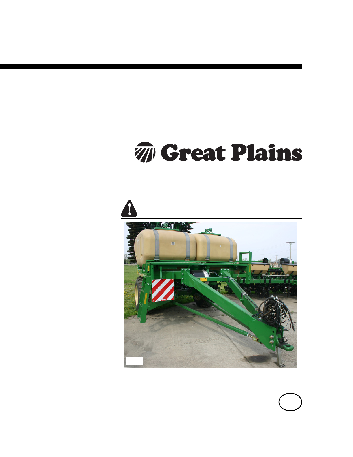
Table of Contents Index
166-369A Update Installation
NTA607HD or NTA2007HD
6 Meter No-Till Air Drills
Manufacturing, Inc.
www.greatplainsmfg.com
Read the update manual entirely. When you see this symbol, the
subsequent instructions and warnings are serious - follow without
exception. Your life and the lives of others depend on it!
32109
Illustrations may show optional equipment not supplied with standard unit.
EN
© Copyright 2011 Printed 05/25/2011 166-370M
Table of Contents Index
Page 2

Table of Contents Index
Table of Contents Index
Page 3

Great Plains Manufacturing, Inc. Cover Index iii
Table of Contents
Important Safety Information ......................................1
General Information .....................................................3
Related Documents........................................................3
Notations and Conventions ............................................3
Call-Outs ....................................................................3
Tools Required ...............................................................4
Regarding Parts .............................................................4
About New Parts ........................................................4
About Existing Parts ...................................................4
Pre-Assembly Preparation .............................................4
Work Location ............................................................4
Update Underside Weldments ....................................5
Configure Implement ......................................................5
Tack Rear Bottom Gussets ............................................5
LH Rear Bottom Gussets............................................5
RH Rear Bottom Gussets...........................................6
Install Nut Blocks............................................................7
Install LH Nut Block ....................................................7
Install RH Nut Block....................................................7
Finish Weld Blocks and Gussets................................7
Install Box Plates............................................................8
Install Corner Gussets....................................................8
Disconnect Implement .................................................9
Prepare Implement.........................................................9
Disconnect Primary Hoses .............................................9
Clear Weight Transfer Cylinders ..................................10
Clear Link Lift Cylinders ...............................................10
Recover Pull Link Components ....................................11
Release Lift-Assist Link ................................................11
Uncouple Cart ..............................................................12
Remove Pull Link .........................................................12
Dismount Hoppers .....................................................13
Disconnect Sensors and Chain ....................................13
Disconnect Level Sensors........................................13
Dismount Rate Sensor .............................................13
Dismount Final Drive Chain...................................... 13
Dismount Meters ..........................................................14
Disconnect Meter Inlet Elbows ................................. 14
Remove Meters ........................................................14
Hoist Hoppers...............................................................15
Release Hopper Mount.............................................15
Remove Hopper Assembly....................................... 15
Update Meters.............................................................16
Remove Existing Top Seal ...........................................16
Remove Meter Flute Shaft ........................................... 16
Remove Old Flanges ............................................... 16
Enlarge Mounting Slots................................................ 17
Drill Weep Holes .......................................................... 17
Install Meter Seal Flange ............................................. 18
Replace Meter Shaft Mount Plates .............................. 18
Replace Right End Plates ........................................ 18
Replace Left End Plates........................................... 19
Install New Top Seal ................................................ 19
Update Cart................................................................. 21
Cart Frame Update Overview ...................................... 21
Rear Gusset Plates (page 22).................................. 21
Front Gusset Triangles (page 23) ............................ 21
Pull Bar Anchors (page 25) ...................................... 21
Meter Mount Tabs (page 27).................................... 21
Install Rear Gussets..................................................... 22
Install Left Rear Gusset............................................ 22
Install Right Rear Gusset ......................................... 22
Install Front Gussets .................................................... 23
Install Right Front Gusset......................................... 23
Install Left Front Gusset ........................................... 23
Install Pull Bar Attach Points........................................ 24
Install Pull Bar Plate ................................................. 24
Install Pull Bar Anchors ............................................ 25
Install Left Anchor ................................................ 25
Install Right Anchor .............................................. 25
Update Meter Mounts .................................................. 26
Position New Meter Mounts ..................................... 26
Prepare Tab Welding Sites ..................................26
Mark Tab Welding Sites ....................................... 27
Attach New Front Tabs ............................................ 27
Install New Meter Mounts......................................... 27
Re-Install Meters.......................................................... 28
Install Hopper Supports............................................ 28
Install Pull Bars ............................................................ 28
Assemble Pull Bars .................................................. 28
Attach Pull Bars........................................................ 29
Update Cart Hydraulics................................................ 30
Route Dedicated Fold Hose ..................................... 32
Mark Dedicated Fan Hose ....................................... 32
Re-Route Fold Hose ................................................ 32
Disconnect Bypass Hose ......................................... 32
Re-Configure Inlet Fittings ....................................... 32
Re-connect Fan Hoses ............................................ 32
Re-Install Hoppers ....................................................... 33
© Copyright 2011 All rights Reserved
Great Plains Manufacturing, Inc. provides this publication “as is” without warranty of any kind, either expressed or implied. While every precaution has been
taken in the preparation of this manual, Great Plains Manufacturing, Inc. assumes no responsibility for errors or omissions. Neither is any liability assumed for
damages resulting from the use of the information contained herein. Great Plains Manufacturing, Inc. reserves the right to revise and improve its products as
it sees fit. This publication describes the state of this product at the time of its publication, and may not reflect the product in the future.
05/25/2011 Cover Index 166-370M
Trademarks of Great Plains Manufacturing, Inc. include: Singulator Plus, Swath Command, Terra-Tine.
Registered Trademarks of Great Plains Manufacturing, Inc. include:
Air-Pro, Clear-Shot, Great Plains, Land Pride, MeterCone, Nutri-Pro, Seed-Lok, Solid Stand, Whirlfilter, Yield-Pro.
Brand and Product Names that appear and are owned by others are trademarks of their respective owners.
Printed in the United States of America
Page 4

iv NTA607HD, NTA2007HD Table of Contents Index Great Plains Manufacturing, Inc.
Align Meters ............................................................. 33
Re-Install Final Drive Chain ..................................... 34
Re-Connect Inlets/Outlets........................................ 34
Re-Install Gears ....................................................... 34
Re-Install Sensors.................................................... 34
Update Hopper Lids ..................................................... 35
Update Implement Frame .......................................... 36
Dismount Lift-Assist ..................................................... 36
Disconnect Lights..................................................... 36
Release Lift Link ...................................................... 36
Dismount Parallel Arms............................................ 37
Remove Pull Link ..................................................... 37
Update Rear Link Anti-Rotation ................................... 37
Update Wing Pivot Anti-Rotation ................................. 38
Update Wing Pivot Extension Tops ............................. 39
Update Front Extension Tops .................................. 39
Update Rear Extension Tops................................... 40
Update Harness.......................................................... 41
Dismount Existing Harnesses ...................................... 41
Enumerate WSMBs ..................................................... 42
Install WSMBs.............................................................. 43
Mount Center WSMBs ............................................. 43
Mount Tower B WSMB......................................... 43
Mount Tower C WSMB ........................................ 43
Mount Wing WSMBs................................................ 44
Mount Tower A (Left Wing) WSMBs .................... 44
Mount Tower D (Right Wing) WSMBs.................. 44
Install Row Harnesses ................................................. 45
Connector ID............................................................ 45
Connect WSMB #1 .................................................. 46
Connect WSMB #4 .................................................. 47
Connect WSMB #2 .................................................. 48
Connect WSMB #5 .................................................. 49
Connect WSMB #3 .................................................. 50
Connect New WSMB #6 .......................................... 51
Install Rear Pull Link.................................................. 52
Pin Link to Main Frame ................................................ 52
Connect Lift-Assist Link ............................................... 52
Connect Lift Assist ....................................................... 53
Re-Install Parallel Arms ............................................... 53
Re-Connect Lights ....................................................... 53
Update Implement Hydraulics .................................. 54
Extend Valve Hoses..................................................... 54
Relocate Valve Group.................................................. 54
Protect Hose Extensions.............................................. 55
Re-Hitch Implement ................................................... 57
Install Front Pull Link.................................................... 57
Re-Connect Lift Link .................................................... 57
Connect Cart and Implement ....................................... 58
Re-Install Link Components......................................... 58
Store Spacers .......................................................... 58
Store New Lift Pins .................................................. 58
Re-Install Link Lift Cylinders ........................................ 59
Re-Install Weight Transfer Cylinders............................59
Route Hoses and Harnesses........................................60
Hose ID for Pull Link Clamping.............................61
Connect Hoses and Harnesses....................................61
Update Markers...........................................................62
Remove Tension Spring ...............................................62
Release Swing Pivot.....................................................62
Release Cylinder ..........................................................62
Remove Arm.................................................................62
Remove Old Pivot Frame .............................................63
Install New Pivot Frame................................................63
Re-Install Arm...............................................................64
Re-Attach Spring ..........................................................64
Update Coulters..........................................................65
Prepare Implement .......................................................65
Replace Coulter Bars ...................................................65
Remove Existing Bar ................................................65
Install New Bar..........................................................66
Close-Out ....................................................................67
Reconfigure Monitor .....................................................67
Appendix A - Reference Information ........................68
Chain Setup..................................................................68
Chain Clip Orientation...............................................68
Chain Slack...............................................................68
Torque Values Chart ....................................................69
Hydraulic Connectors and Torque................................70
Appendix D - Drawings ..............................................71
160-795D PIN RETAINER TAB....................................71
160-801D FRAME NUT BLOCK...................................72
160-802D FRAME EXT BOT GUSSET LH REWORK .73
160-803D FRAME EXT BOX PLATE ...........................74
160-804D FRAME EXT BOT GUSSET LH REWORK .75
160-805D FRAME EXT BOT GUSSET REWORK......76
160-806D FRAME EXT BOT GUSSET REWORK.......77
160-807D FRAME EXT CORNER GUSSET................78
160-808D FRAME EXT 100 DEG GUSSET.................79
160-809D FR EXT 100 DEG GUSSET REWORK .......80
160-810D FR EXT 100 DEG GUSSET REWORK .......81
160-811D WING HINGE PIN ROTATION STOP .........82
Appendix G - Glossary...............................................83
Part Descriptor Abbreviations.......................................83
Appendix H - Harness ................................................85
Tower ID .......................................................................85
Secondary Hose Routing, 40-Row ...............................86
Turrets, 40-Row, Double-Shoot, Seed..................86
Turrets, 40-Row, Double-Shoot, Fertilizer ............87
Harness (LH) ................................................................88
Appendix P - Part Lists ..............................................90
Existing Parts Affected..............................................90
166-369A New Parts.................................................94
Index ............................................................................97
166-370M Table of Contents Index 05/25/2011
Page 5
Great Plains Manufacturing, Inc. Table of Contents Index 1
Important Safety Information
Look for Safety Symbol
The SAFETY ALERT SYMBOL indicates there is a
potential hazard to personal safety involved and extra
safety precaution must be taken. When you see this
symbol, be alert and carefully read the message that follows it. In addition to design and configuration of equipment, hazard control and accident prevention are
dependent upon the awareness, concern, prudence and
proper training of personnel involved in the operation,
transport, maintenance and storage of equipment.
Be Aware of Signal Words
Signal words designate a degree or level of hazard seriousness.
DANGER indicates an imminently hazardous situation
which, if not avoided, will result in death or serious injury.
This signal word is limited to the most extreme situations,
typically for machine components that, for functional purposes, cannot be guarded.
WARNING indicates a potentially hazardous situation
which, if not avoided, could result in death or serious
injury, and includes hazards that are exposed when
guards are removed. It may also be used to alert against
unsafe practices.
CAUTION indicates a potentially hazardous situation
which, if not avoided, may result in minor or moderate
injury. It may also be used to alert against unsafe practices.
Possible Chemical Hazard:
Have chemical gloves, respirator and goggles available. Have
clean wash water available. Have the MSDSa available for
recently applied dry fertilizer. This installation requires disconnecting one or two meters. Fertilizer can be hazardous,
and can cause lung irritation, respiratory distress, sickness or
poisoning. Know what steps to take if adverse exposure occurs.
Prepare for Emergencies
▲ Be prepared if a fire starts.
▲ Keep a first aid kit and fire extinguisher handy.
▲ Keep emergency numbers for doctor, ambulance, hospital
and fire department near phone. Have contact numbers
available.
a. MSDS: Material Safety Data Sheet
05/25/2011 Table of Contents Index 166-370M
Page 6
2 NTA607HD or NTA2007HD Table of Contents Index Great Plains Manufacturing, Inc.
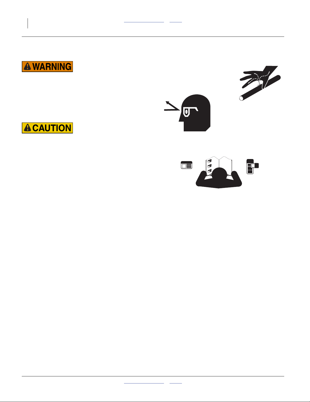
Avoid High Pressure Fluids
High Pressure Fluid Hazard:
Wear gloves and goggles when opening hydraulic connections.
Use cardboard to check for leaks. This update requires opening existing hydraulic connections. Pre-installation steps may
not relieve all residual pressure. This update requires making
new hydraulic connections. Check for leaks carefully. If an
accident occurs, seek immediate medical assistance from a
physician familiar with this type of injury.
Sharp Object Hazard:
Be careful working near openers. Discs are sharp.
Be Familiar with Safety Decals
▲ Read and understand the “Safety Decals” in the Operator
manual.
▲ Read all instructions noted on the decals.
▲ Keep decals clean. Replace damaged, faded and illegible
decals.
166-370M Table of Contents Index 05/25/2011
Page 7
Great Plains Manufacturing, Inc. Table of Contents Index 3
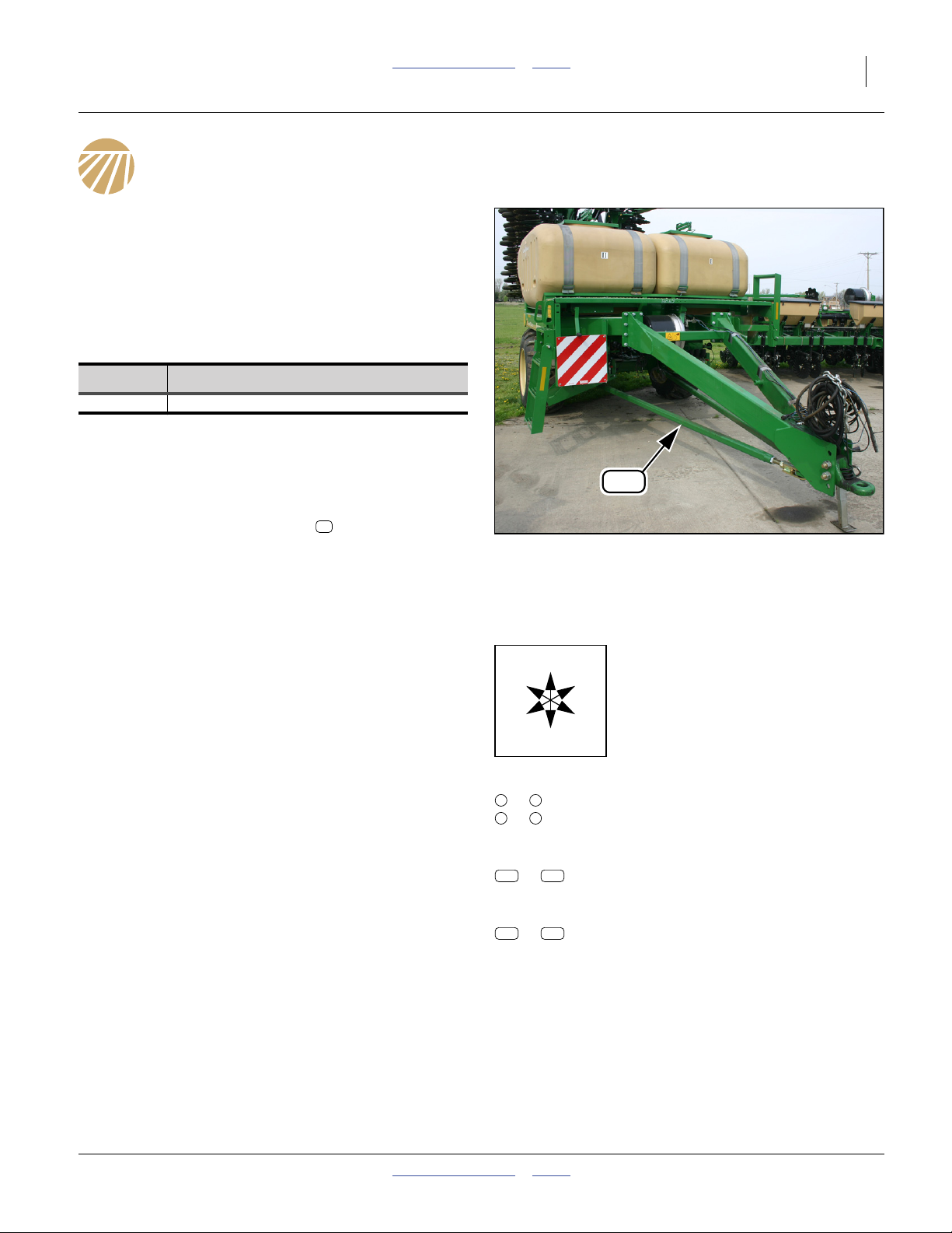
General Information
These instructions explain how to update multiple drill
components. The kit improves drill durability in extremely
challenging conditions, and adds some convenience features.
One kit updates drill. Applies to models:
NTA607HD-4006 Option 72
NTA2007HD-4006 Option 72
These instructions apply to an installation of:
Kit Kit Description
166-369A 6 Meter No-Till Air Drill
• This kit applies only to dual-hopper (Option 72) drills.
It does apply to single-hopper models (whether single
150 bu or single 82 bu with liquid fertilizer tanks). The
kit is not fully documented for 64-row drills.
• This kit is not required for drills manufactured after
May 2011. If the lower pull-bars are present, kit
features are already installed.
• This kit is not required for any NTA607- or NTA2007(non-HD) drills.
91
916
Figure 1
Kit Installed
32109
Related Documents
Have your drill Operator and Parts manuals available for
implement operations and parts identification. Have the
Pre-Delivery manual available for disassembly.
166-283M
166-283P
110011512
110011544
166-283Q
113-850M
All of the above drill manuals, including Pre-Delivery, are
available as PDF files on the Great Plains web site:
Manuals > No-Till Drills > No-Till Air Drills >
NTA607HD & NTA2007HD No-Till Air Drill
NTA607HD/2007HD Operator
NTA607HD/2007HD Parts
ACC (Air Cart Control) User Level 2/3
NTA607HD Quick Setup Guide
NTA607HD/2007HD Pre-Delivery
20ft Swing-Arm Marker Installation
Notations and Conventions
U
F
L
D
Call-Outs
1 9
to
a z
to
101
to Three-digit callouts in the range 101 to 239
900 982
to Three-digit callouts in the range 900 to 982
Single-digit or single-letter callouts identify
components in the currently referenced
Figure. These numbers may be reused for
different items from page to page.
239
reference existing parts from the list on
page 90.
reference new parts from the list on page 94.
“Left”/LH and “Right”/RH are facing in
the direction of machine travel. An ori-
R
entation rose in the line art illustrations
shows the directions of Left, Right,
Front, Back, Up, Down.
B
05/25/2011 Table of Contents Index 166-370M
Page 8

4 NTA607HD or NTA2007HD Table of Contents Index Great Plains Manufacturing, Inc.
Tools Required
• suitable tractor for lowering and unfolding drill
• hoist or other lifter with a capacity of at least
300 kg (660 pounds)
• jacks, supports or stands with a capacity of 1500 kg
(3500 pounds), for rear frame support
• fire extinguisher
• wire or rod welder, and welding safety equipment
• ground (earthing) rod, cable and clamp (or access to
suitable electrical safety ground reference conductor)
• welding blankets
• silicone sealant
• clamps (for welding), covering sizes:
13 mm (1⁄2in)
2.5 cm (1.0 in)
21 cm (8.25 in)
27 cm (10.5 in
• MSDSb for fertilizers recently applied
• chemical safety equipment (see DANGER on page 1)
• vehicle jack
• fish line for pulling hydraulic hose through tongue
• cutting wheel or grinder suitable for enlarging a slot
from 9 mm to 13mm wide
• basic hand tools, including drill bit size:
6 to 7 mm (1⁄4in, letter size E)
• Great Plains 821-001C green spray paint,
or green exterior enamel close to Pantone 356C,
DuPont 262 or PPG 43817
Regarding Parts
About New Parts
To aid in part identification, engineering drawings for
many new parts are included in “Appendix D - Draw-
ings”, pages 71 to 82.
After identifying a new part, just prior to installation,
remove and discard any tape or tags with part numbers
that might interfere with installation. Part numbers not
removed, or applied with grease or paint pencil, may be
removed at close-out.
A number of new cotter and roll pins are provided. Use
as needed when saved parts are unserviceable.
A large number of cable ties are provided. Use as
needed to secure cables and hoses. They are not called
out at every step.
About Existing Parts
This kit relies on re-use of some parts. Follow “remove
and save” instructions carefully. Parts that are “not
re-used” may be salvaged or discarded. They are not
returned to Great Plains.
Pre-Assembly Preparation
1. Perform a clean-out of both hoppers. This update
requires meter removal.
Work Location
2. Move the drill to a location with:
• ample room to unfold and separate the implement
from the cart
• adequate illumination
• a surface that is non-flammable, and has no
deposits or residues of flammable substances
• clear surface beneath for recovery of any falling or
dropped parts
b. Material Safety Data Sheet - consult the fertilizer supplier
166-370M Table of Contents Index 05/25/2011
High Pressure Fluid Hazard:
Wear gloves and goggles when opening hydraulic connections.
Use cardboard to check for leaks. This update requires opening existing hydraulic connections. Setting circuits to Float
may not relieve all residual pressure. This update requires
making new hydraulic connections. Check for leaks carefully.
If an accident occurs, seek immediate medical assistance from
a physician familiar with this type of injury.
Page 9
Great Plains Manufacturing, Inc. Table of Contents Index 5
Update Underside Weldments
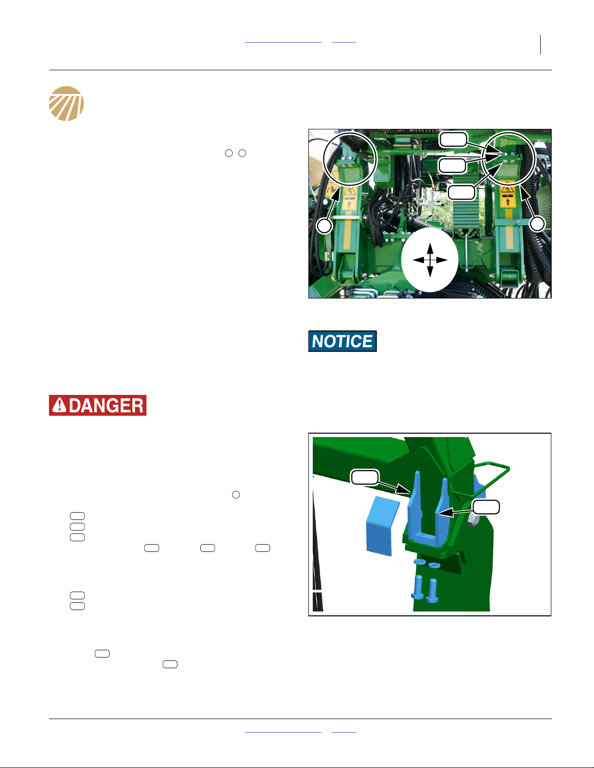
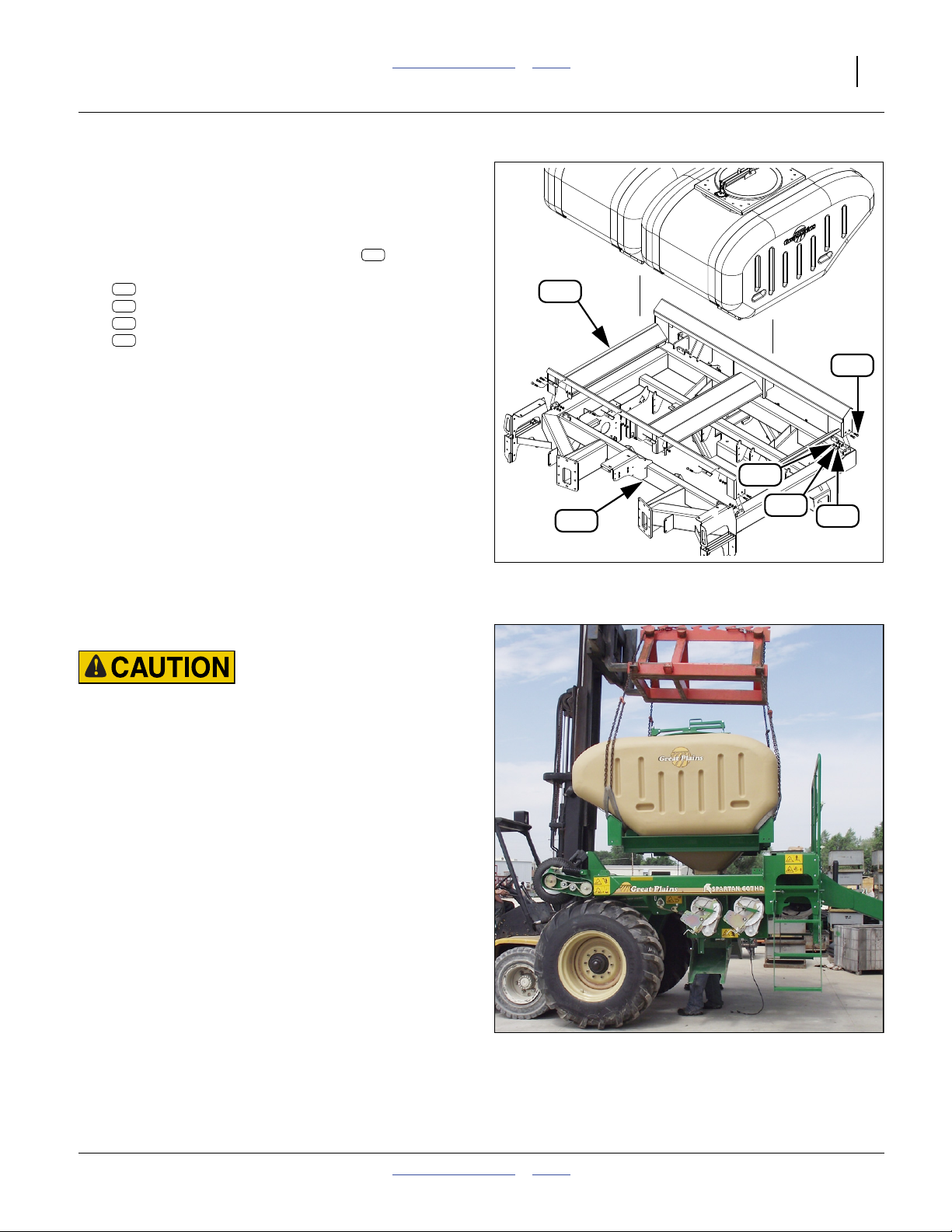
Refer to Figure 2
Gussets, nut blocks and a box plate are added to the
underside of the wing pivot extensions (4 , locations,
two on each wing). This work is considerably easier with
the implement folded, and needs to be done prior to
cart-implement separation.
B F
Configure Implement
3. Raise, fold and configure as if for transport (lift locks
and wing fold locks installed). Set all hydraulic
remotes to Float to relieve pressure in lines.
4. Disconnect all harnesses and cables at cart hitch.
5. Take steps to protect hoses and cables near weld
regions. Cover with welding blankets, or temporarily
remove, as needed.
Tack Rear Bottom Gussets
LH Rear Bottom Gussets
Start with the left (LH) side. The left and right side new
parts are not identical, although they are similar and
install in mirror-image locations.
179
190
174
F
B
U
F
B
D
Figure 2
Underside Work Locations
Equipment Damage Risk:
Disconnect all electrical connections between cart and tractor
prior to welding. Welding can induce high voltages and/or
high current flows that could damage sensors, WSMB and
WSMTs on the cart or implement.
Q0113
Crushing Hazard:
Remove only the underside bolts. Do not remove the
cross-bolts or the top side bolts. Removing all the fasteners at
a joint could allow a dangerous joint separation resulting in
serious injury or death, and extensive machine damage.
Refer to Figure 2
6. At the Back wing pivot extension joint , remove
two sets:
179
803-027C NUT HEX 3/4-10 PLT
190
804-023C WASHER LOCK SPRING 3/4 PLT
174
802-910C RHSNB 3/4-10 X 2 GR5 PLT
Save the washer . The nut and bolt are
not re-used.
Refer to Figure 3
7. Select one each new:
908
160-804D FRAME EXT BOT GUSSET LH REWORK
909
160-805D FRAME EXT BOT GUSSET REWORK
Hold these in their intended positions. Mark paint for
removal.
8. Remove paint. Tack weld gusset plates in position.
908
Plate is to implement front, against the existing
smaller gusset. Plate is to implement rear,
against the existing smaller gusset. Place both as
close to the joint and up against the wing as allowed
by pre-existing weld fillets.
190 179 174
909
B
908
Figure 3
LH Rear Underside Gussets
909
Q0120
05/25/2011 Table of Contents Index 166-370M
Page 10
6 NTA607HD or NTA2007HD Table of Contents Index Great Plains Manufacturing, Inc.
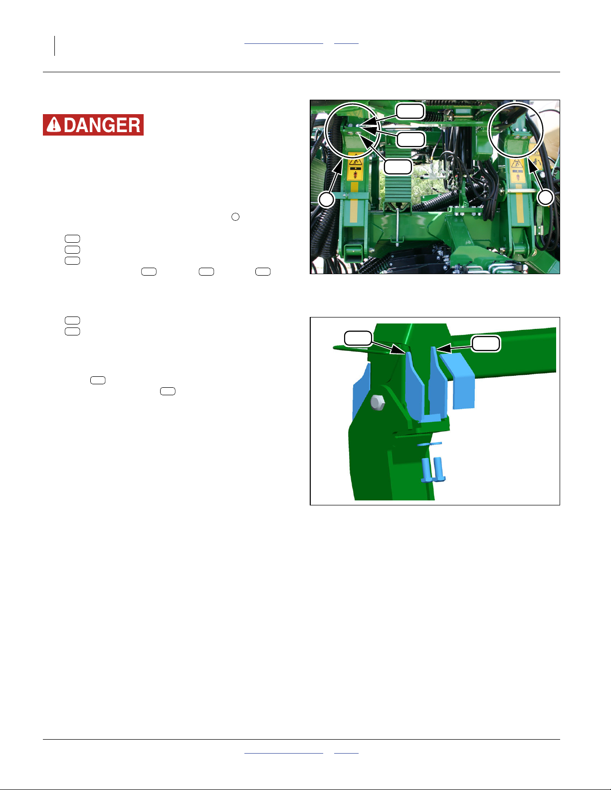
RH Rear Bottom Gussets
Crushing Hazard:
Remove only the underside bolts. Do not remove the
cross-bolts or the top side bolts. Removing all the fasteners at
a joint could allow a dangerous joint separation resulting in
serious injury or death, and extensive machine damage.
Refer to Figure 4
9. At the Back wing pivot extension joint , remove
two sets:
179
803-027C NUT HEX 3/4-10 PLT
190
804-023C WASHER LOCK SPRING 3/4 PLT
174
802-910C RHSNB 3/4-10 X 2 GR5 PLT
Save the washer . The nut and bolt are
190 179 174
not re-used.
Refer to Figure 5
10. Select one each new:
906
160-802D FRAME EXT BOT GUSSET LH REWORK
910
160-806D FRAME EXT BOT GUSSET REWORK
Hold these in the their intended positions. Mark
paint for removal.
11. Remove paint. Tack weld gusset plates in position.
906
Plate is to implement front, against the existing
smaller gusset. Plate is to implement rear,
910
against the existing smaller gusset. Place both as
close the joint and up against the wing as allowed
by pre-existing weld fillets.
B
B
910
179
190
174
Figure 4
Remove RH Fasteners
906
F
Q0113
Figure 5
Q0120
RH Rear Underside Gussets
166-370M Table of Contents Index 05/25/2011
Page 11
Great Plains Manufacturing, Inc. Table of Contents Index Update Underside Weldments 7
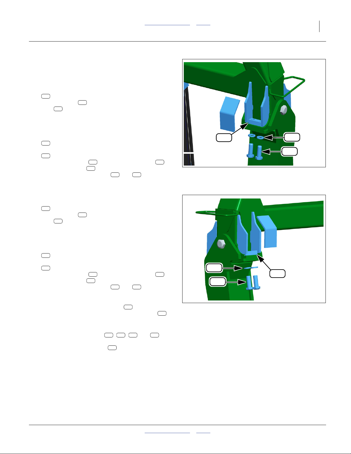
Install Nut Blocks
Install LH Nut Block
Refer to Figure 6
12. Select one new:
905
160-801D FRAME NUT BLOCK
This nut block replaces the removed individual
179
nuts . Prepare the site for welding. Using the nut
block as a template, mark an area for a width of at
least 5 cm (2 in) along the edges of the block.
Remove the paint from the pivot extension plate.
13. Select two new:
943
802-064C HHCS 3/4-10X2 GR5
and two saved:
190
804-023C WASHER LOCK SPRING 3/4 PLT
Hold the nut block in place with the bolts
and lock washers . Tack weld the nut block to the
wing and the new gussets ( and ).
Install RH Nut Block
Refer to Figure 7
14. Select one new:
905
160-801D FRAME NUT BLOCK
This nut block replaces the removed individual
179
nuts . Prepare the site for welding. Using the nut
block as a template, mark an area for a width of at
least 5 cm (2 in) along the edges of the block.
Remove the paint from the pivot extension plate.
15. Select two new:
943
802-064C HHCS 3/4-10X2 GR5
and two saved:
190
804-023C WASHER LOCK SPRING 3/4 PLT
Hold the nut block in place with the bolts
and lock washers . Tack weld the nut block to the
wing and the new gussets ( and ).
905
905 943
190
908 909
905
905 943
190
906 910
190
943
905
Figure 6
LH Nut Block
190
943
Q0119
905
Finish Weld Blocks and Gussets
16. Back off all four of the new bolts until the
threads are just emerging from the nut blocks .
943
905
Figure 7
RH Nut Block
This protects the block threads from weld splatter,
and leaves the bolts loose for checking.
17. Finish weld the gussets ( , , and ) all
906 908 909 910
around (as accessible) with a fillet of 7 mm (1⁄4in.).
Finish weld the nut blocks along any accessible
905
edges.
18. Clean off any slag and weld splatter.
05/25/2011 Table of Contents Index 166-370M
Q0120
Page 12

8 NTA607HD or NTA2007HD Table of Contents Index Great Plains Manufacturing, Inc.
Install Box Plates
Refer to Figure 8
19. Select two new:
907
160-803D FRAME EXT BOX PLATE
Position each plate to fully enclose the space define
by the new gussets, the existing joint plate and the
wing rear tube. Tack weld in place.
20. Finish weld all around on each box plate.
21. Clean off any weld splatter and slag.
22. Remove or mask the new bolts . Paint the new
gussets and each entire welded area green.
23. Insert the new bolts . Tighten to Grade 5 torque
943
specification.
24. Re-connect any hydraulic hoses or cables removed
for weld protection. They may be required for unfolding and lowering.
943
907
Figure 8
Box Plate
Q0120
Install Corner Gussets
Refer to Figure 9
The corner gussets are added near the joint
between the wing and the pivot extensions, at the junction between the rear-most (longer) of the existing
gussets , and the front-to-back wing tie plate .
1 2
25. Remove paint at the plate and gusset edges where
the corner gussets are to be installed.
26. Select two new:
911
160-807D FRAME EXT CORNER GUSSET
Tack weld each at the plate/gusset junctions.
27. Finish weld with a fillet of 9 cm (3⁄8in.).
28. Clean off all weld splatter and slag. Paint green.
911
2
1
911
Figure 9
Corner Gusset
Q0121
166-370M Table of Contents Index 05/25/2011
Page 13
Great Plains Manufacturing, Inc. Table of Contents Index 9
Disconnect Implement
The pull link that is the hitch between implement and
cart is replaced during this update. Removing the old link
early eases access for cart and implement updates.
106
Prepare Implement
29. Re-connect all harnesses and cables at cart hitch.
30. Raise and unfold the implement.
31. Set jacks or stands under the rear mainframe, under
the weights. Set their height to slightly higher than
the lowered position of the frame.
32. Lower the implement.
33. Set all hydraulic remotes to Float to relieve pressure.
34. Connect jack to tongue. Unhitch tractor. Disconnect
all electrical connections between tractor and cart.
35. Adjust tongue height with jack until bottom edges of
hitch side plates are level.
Disconnect Primary Hoses
Refer to Figure 10
36. Verify that each primary air hose , at the meter
end, is marked with the letter of the port to which it
is connected. If any markings are missing, write the
port letter on tape, and wrap it around the hose.
37. The the meter outlets, loosen eight:
159
800-180C 2 1/2 AIR HOSE BAND CLAMP
Slide these clamps several spirals onto to the
hoses . Re-tighten the clamps enough to prevent loss. Pull the hoses off the meter outlets.
132
159
132
Equipment Damage Risk:
Disconnect all electrical connections between cart and tractor
prior to welding. Welding can induce high voltages and/or
high current flows that could damage sensors, WSMB and
WSMTs on the cart or implement.
159
132
Figure 10
Primary Air Hoses at Meters
05/25/2011 Table of Contents Index 166-370M
Q0114
Page 14
10 NTA607HD or NTA2007HD Table of Contents Index Great Plains Manufacturing, Inc.
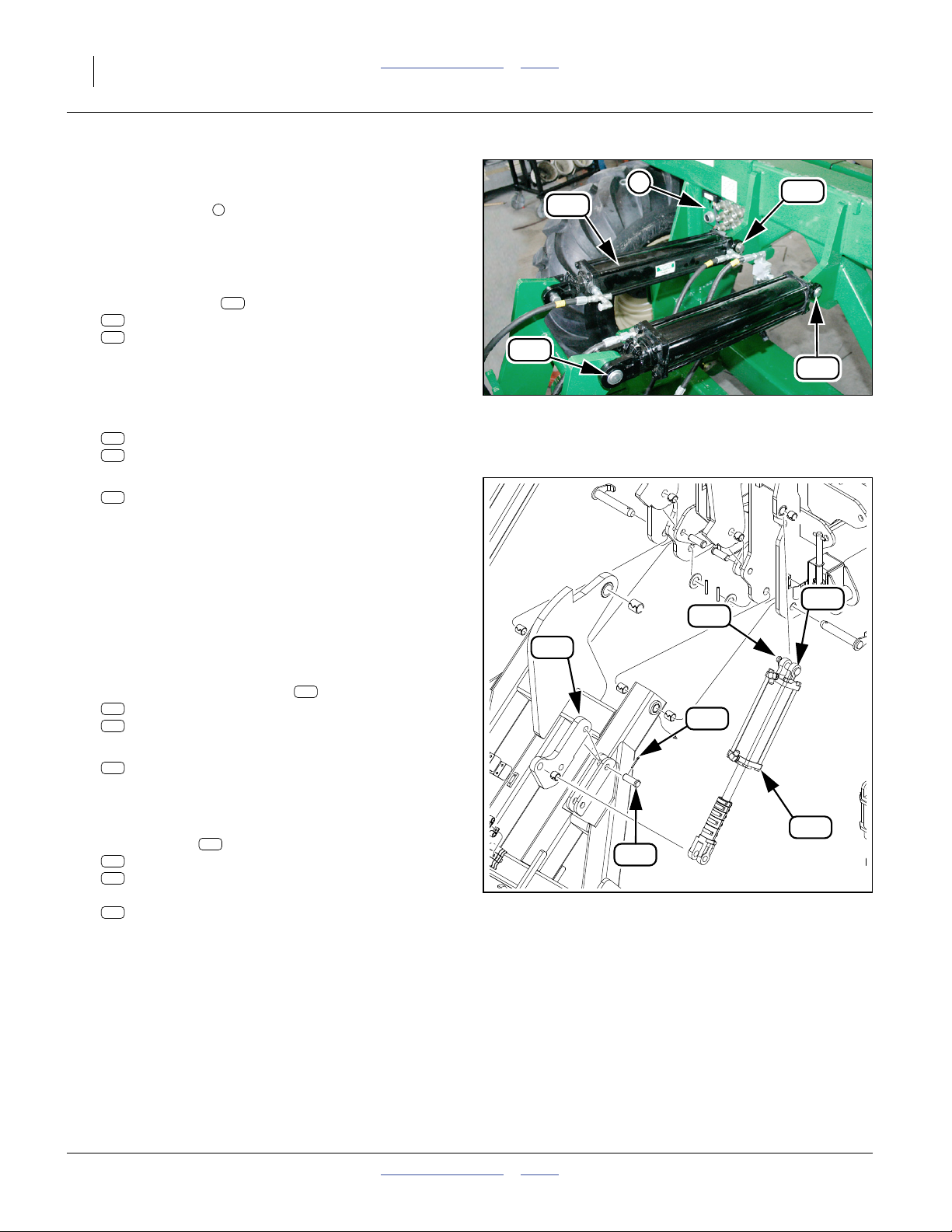
Clear Weight Transfer Cylinders
Refer to Figure 11
38. At the bulkhead at the left rear of the cart, unplug
1
all hydraulic hoses and cables. Some cable connects may not be at the bulkhead.
39. At the cart-implement pull link, remove and save
two sets of base end pins of the weight transfer
(upper) cylinders :
141
2A0132 MW PIN CLIP
140
2A0206 MW PIN SHORT
206
40. Release the cylinder hoses from any clamps on the
pull link.
41. At the rod ends of the weight transfer cylinders,
remove and save two sets:
141
2A0132 MW PIN CLIP
197
805-124C PIN CLEVIS 1 X 3 11/16 GR5 PLT
42. Lift the cylinders
206
810-219C CYL 3.5X16X2 ROD (TIE ROD)
off the pull link and rest them on the implement
frame. It may not be necessary to disconnect their
hoses.
206
197
Clear Weight Transfer Cylinders
1
Figure 11
141
140
Q0047
Clear Link Lift Cylinders
Refer to Figure 12
43. Release the cylinder hoses from any clamps on the
pull link.
44. Remove and save the clevis pins at each end of the
(lower) pull link lift cylinders :
141
2A0132 MW PIN CLIP
197
805-124C PIN CLEVIS 1 X 3 11/16 GR5 PLT
45. Lift the cylinders
205
810-170C CYL REP 3.5X10X1.25 ROD (TIE)
off the pull link and rest them on the implement
frame. It may not be necessary to disconnect their
hoses.
46. At the lift lugs , remove and save two sets:
195
805-104C PIN COTTER 3/16 X 1 1/2 PLT
199
805-187C PIN CLEVIS 1 X 2 1/4 GR5 PLT
115
then remove and save the lugs:
115
160-754D NTA607 PULL LINK CYLINDER LUG
205
115
141
195
199
Figure 12
Clear Link Lift Cylinders
197
205
Q0129
166-370M Table of Contents Index 05/25/2011
Page 15
Great Plains Manufacturing, Inc. Table of Contents Index Disconnect Implement 11
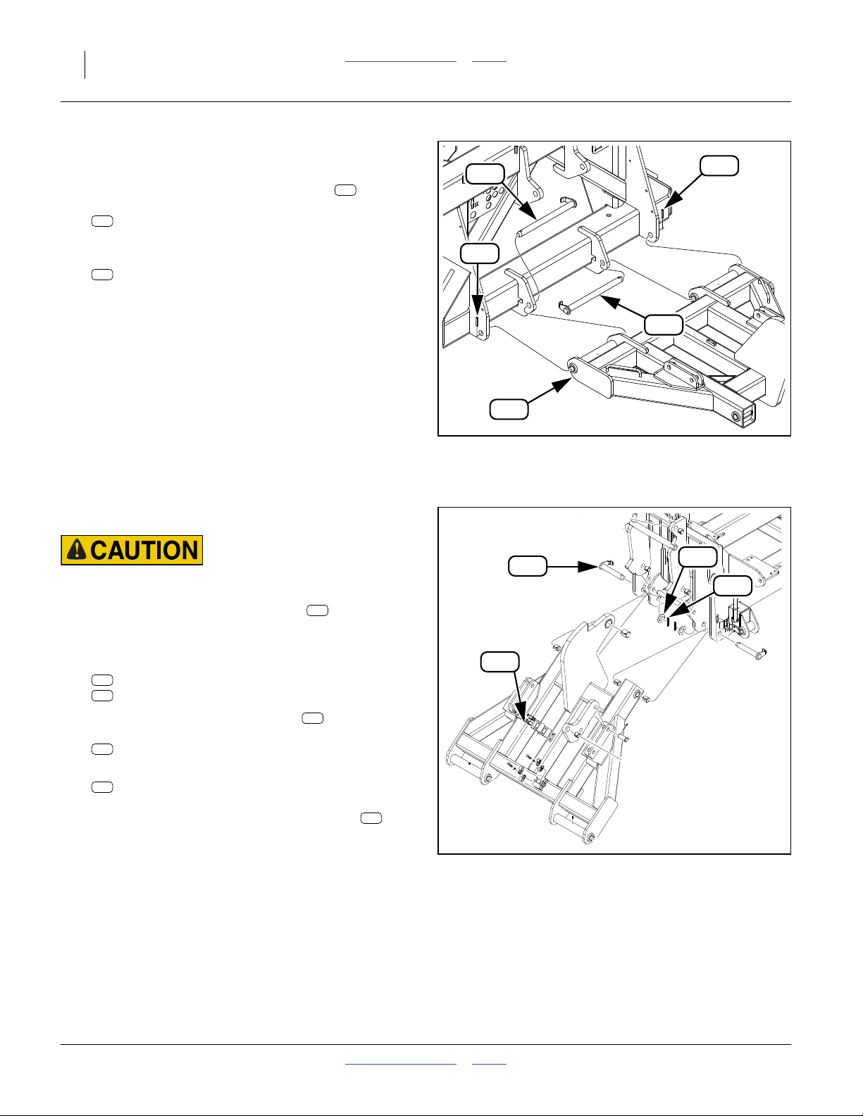
Recover Pull Link Components
Refer to Figure 13
47. Remove and save all clamps and their fasteners:
155
502-068D HYD HOSE CLAMP BRACKET
156
800-052C HOSE CLIP 5/8 I.D.
158
800-064C HOSE CLIP 13/16 ID
164
802-007C HHCS 5/16-18X3/4 GR5
165
802-012C HHCS 5/16-18X1 1/2 GR5
169
802-115C HHCS 5/16-18X2 GR5
184
804-009C WASHER LOCK SPRING 5/16 PLT
plus the:
116
160-760D TRANSPORT LOCK PIN 1 X 8.25
117
160-763D NTA607HD PIN STORAGE BRACKET
158
165
184
156
116
117
155
184
164
156
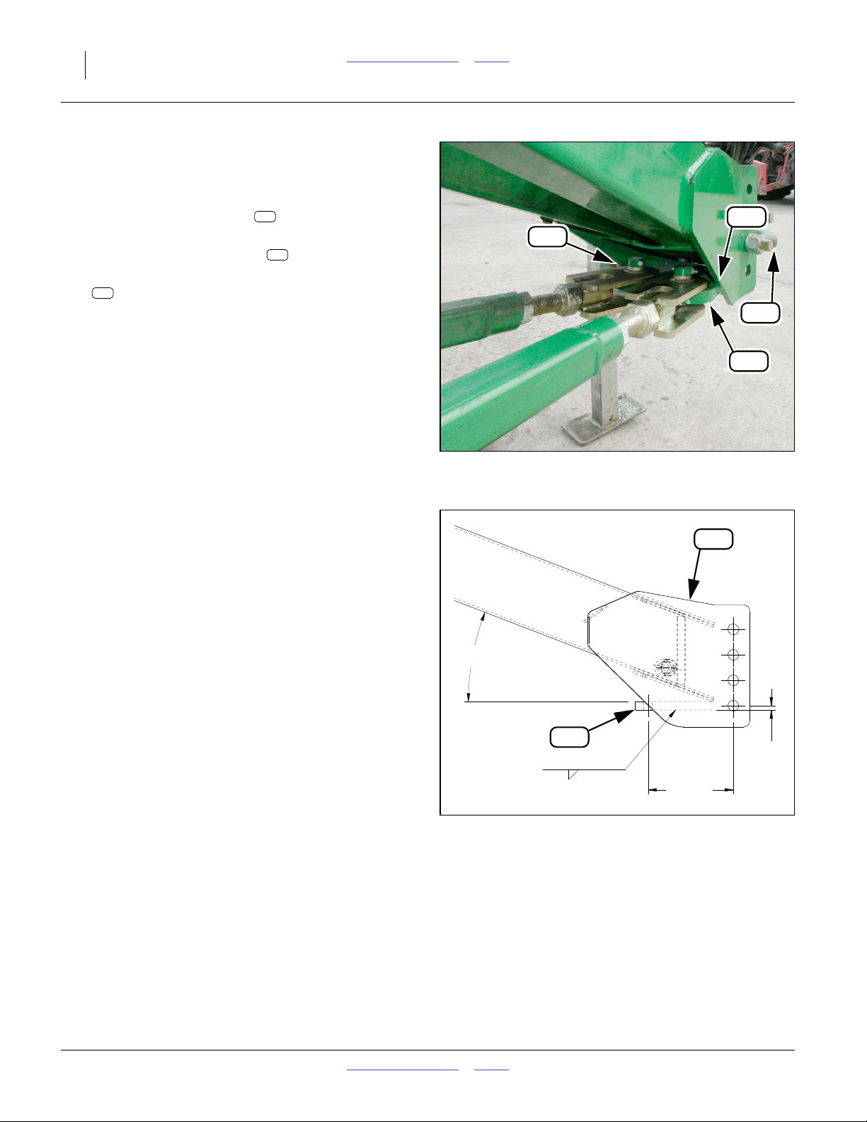
Release Lift-Assist Link
Refer to Figure 14
48. Verify that there is no tension at the connection
between the lift-assist link and the front pull link
106
lug .
49. Remove and save one roll pin and washer:
196
805-117C PIN ROLL 1/4 X 2 1/2 PLT
194
804-117C WASHER FLAT 1/4 HARD ASTMF436
then the link pin and remaining washer
118
160-781D PIN 1 1/2 X 4 USABLE 1045
194
804-117C WASHER FLAT 1/4 HARD ASTMF436
112
169
196
184
158
Clamp Recovery
106
194
155
Figure 13
112
118
Q0068
196
194
Figure 14
Lift-Assist Link
05/25/2011 Table of Contents Index 166-370M
31423
Page 16
12 NTA607HD or NTA2007HD Table of Contents Index Great Plains Manufacturing, Inc.
Uncouple Cart
Refer to Figure 15
50. At the forward (cart) end of the pull link , remove
and save two roll pins:
200
805-255C PIN ROLL 3/8 X 2 1/2 PLT
51. Support the weight of the pull link front end (or the
weight of the entire link), then remove and save two:
110
160-323H PIN WLDMNT 1.25 X 15.66 NR
106
110
200
200
110
106
Remove Pull Link
Pinch / Crush Hazards:
Use an adequate hoist or lifter. Use three or more lines. Place
lines where they cannot slip. The weldment weighs over
270 kg (600 pounds).
Refer to Figure 16
52. Remove and save two roll pins and washers:
200
805-255C PIN ROLL 3/8 X 2 1/2 PLT
193
804-039C WASHER FLAT 1 1/4 SAE PLT
53. Support the weight of the pull link . Remove and
save two pivot pins:
104
160-201H WING PIVOT PIN WELDMENT
54. Remove the weldment:
106
160-315H NTA607HD FRONT PULL LINK WLDMT
This weldment, and its bushings, are not re-used.
It is replaced by a new 160-315H weldment at
step 331 on page 57.
106
106
902
106
104
Figure 15
Pull Link at Cart
31422
193
200
Figure 16
Remove Pull Link
166-370M Table of Contents Index 05/25/2011
Q0129
Page 17
Great Plains Manufacturing, Inc. Table of Contents Index 13
Dismount Hoppers
Hoppers and their mount, are removed to:
• provide clearance to install new hopper braces;
• protect the hoppers from welding damage; and,
• ease update of meter supports.
The hoppers must be empty.
Supports are required. If an original export shipping rack
is available, it would be ideal. Otherwise, provide two
wide or four narrow supports of equal height, at least
33 cm (13 in.) in height.
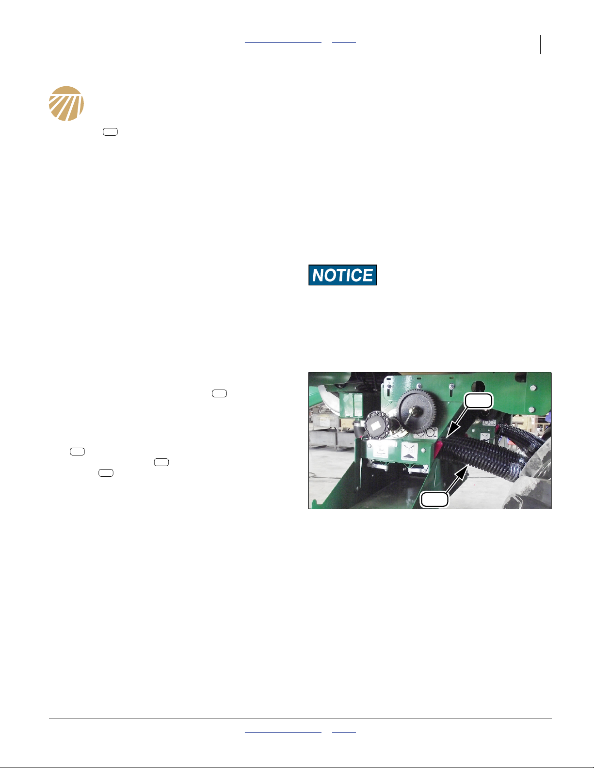
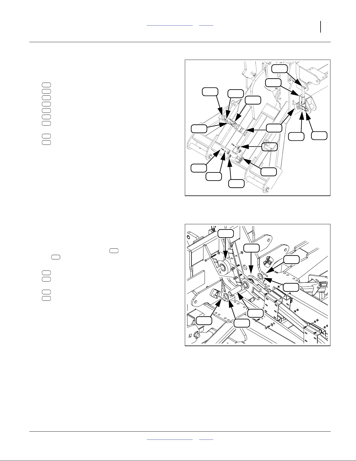
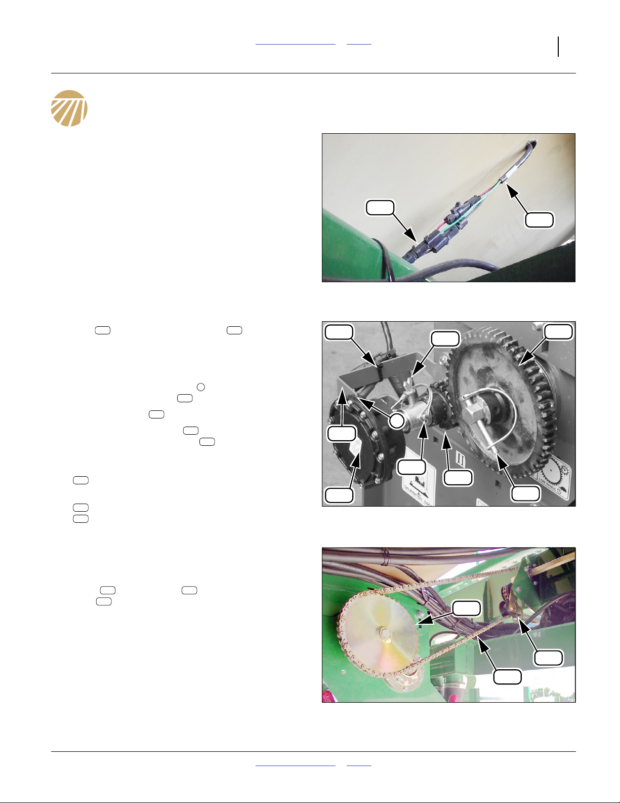
Disconnect Sensors and Chain
151
146
Disconnect Level Sensors
Refer to Figure 17
55. At each hopper, disconnect the hopper level sensor
146 151
lead from the air cart harness .
Dismount Rate Sensor
Refer to Figure 18
56. At the left end of each meter box, disconnect the
sensor’s anti-rotation strap ( , not visible in Figure),
from the sensor mount .
57. Cut the cable tie .
58. Loosen the thumbscrew .
Swing away the rate sensor .
Re-tighten the thumbscrew to prevent loss.
59. Remove and save two pins:
198
805-155C PIN WIRE RETAIN 5/16 X 2 1/2
60. Remove and save both gears:
130
168-243D GEAR 54 TOOTH QUICK CHANGE
204
808-192C GEAR 17 TOOTH QUICK CHANGE
157
2
162
162
145
Dismount Final Drive Chain
Refer to Figure 19
61. At the right end of each meter, loosen the final drive
221 102
idlers . Lift the chain off the meter input
129
gear . It is not necessary to remove the chain
entirely. The sprocket is left installed.
157
139
145
Figure 17
Hopper Level Sensor Lead
162
2
198
204
Figure 18
Rate Sensor
129
Q0101
130
198
31373
221
102
Figure 19
Final Drive Chain
05/25/2011 Table of Contents Index 166-370M
Q0033
Page 18

14 NTA607HD or NTA2007HD Table of Contents Index Great Plains Manufacturing, Inc.
Dismount Meters
Disconnect Meter Inlet Elbows
Refer to Figure 20 and Figure 21
62. At the meter inlets, loosen each clamp . Slide it
well onto the elbow . Re-tighten enough to pre-
219
160
vent clamp loss. It may be difficult to remove elbows
until the meter is freed in its mounts.
63. Close the meter chute (not shown).
Remove Meters
Pinch / Crush Hazards:
Use a jack or at least two strong people. The meter assembly
weighs up to 78 kg (171 pounds), with chute installed.
Refer to Figure 21 (depicting a meter with chute removed)
64. Loosen the six nuts that secure the meter to
its mounts . Pull the meter back from the
elbows .
138
219
65. With the loose bolts still in place, allow the meter to
drop in the vertical slots of the mount. If it does not
drop, this suggests that the meter vent tubes have
bonded to the vent structure inside the hopper.
66. With the meter freed from the hopper vent structure,
support the full weight of the meter. At each meter,
completely remove six sets (not all shown):
176
803-014C NUT HEX 3/8-16 PLT
186
804-013C WASHER LOCK SPRING 3/8 PLT
185
804-011C WASHER FLAT 3/8 USS PLT
172
802-155C RHSNB 3/8-16X1 1/4 GR5
These fasteners are replaced by new1⁄2in fasteners
at step 158 on page 28.
67. At the rear end of the existing meter mounts ,
remove and save six sets (not shown):
177
803-020C NUT HEX 1/2-13 PLT
187
804-015C WASHER LOCK SPRING 1/2 PLT
167
802-082C HHCS 1/2-13X1 3/4 GR5
and the two:
138
266-174D METER BOX MOUNT
The mount is not re-used.
176 124
138
124
219
Meter Hoses
Confined Space and Agricultural Chemical Hazards:
If the meter vents have bonded to the hopper vent structure,
hopper entry may be required to free the connection. Consult
the Operator manual (166-283M) for safe entry procedures.
The hopper may be a low-oxygen environment with risk of
asphyxiation. Dust and chemical residues can be an inhalation
and skin contact hazard, causing irritation, respiratory distress, illness or death.
176
160
Figure 20
138
31149
219
124
160
Figure 21
Q0030
Lowering Meter on a Jack
166-370M Table of Contents Index 05/25/2011
Page 19
Great Plains Manufacturing, Inc. Table of Contents Index Dismount Hoppers 15
Hoist Hoppers
Release Hopper Mount
Refer to Figure 22 (shown with hoppers floating - leave hoppers attached to mount)
68. At each corner of the hopper mount , remove
and save two sets (8 sets total) of:
177
803-020C NUT HEX 1/2-13 PLT
187
804-015C WASHER LOCK SPRING 1/2 PLT
188
804-017C WASHER FLAT 1/2 USS PLT
167
802-082C HHCS 1/2-13X1 3/4 GR5
122
122
167
177
Remove Hopper Assembly
Pinch / Crush Hazards:
Use an adequate hoist or lifter. Use three or more lines, each
rated for at least half the load. Place lines where they cannot
slip. The assembly weighs nearly 550 kg (1200 pounds).
Refer to Figure 23
69. Attach lines to the hopper assembly. Carefully lift it
off the cart frame. Set it on the supports.
121
Figure 22
Hopper Mount at Frame
187
188
31108
Figure 23
Hoisting Hopper Mount
05/25/2011 Table of Contents Index 166-370M
Q0102
Page 20
16 NTA607HD or NTA2007HD Table of Contents Index Great Plains Manufacturing, Inc.
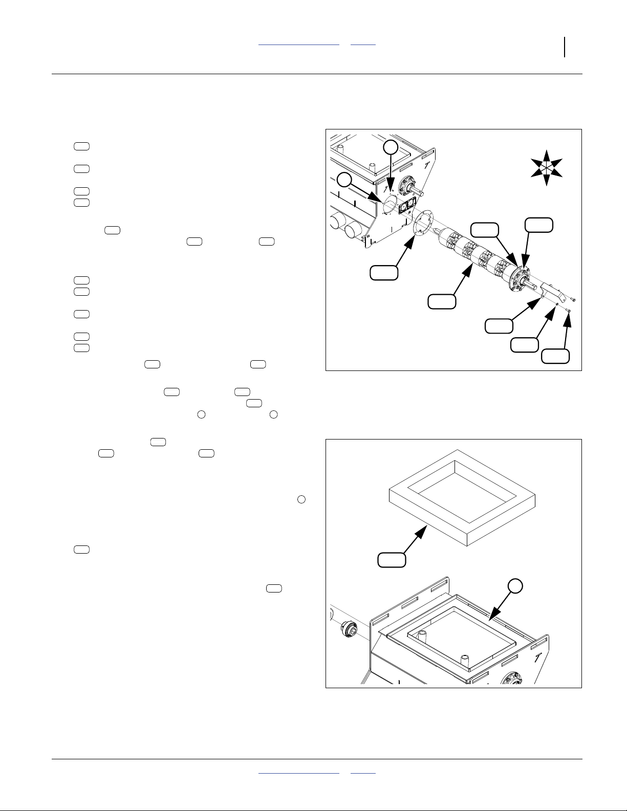
Update Meters
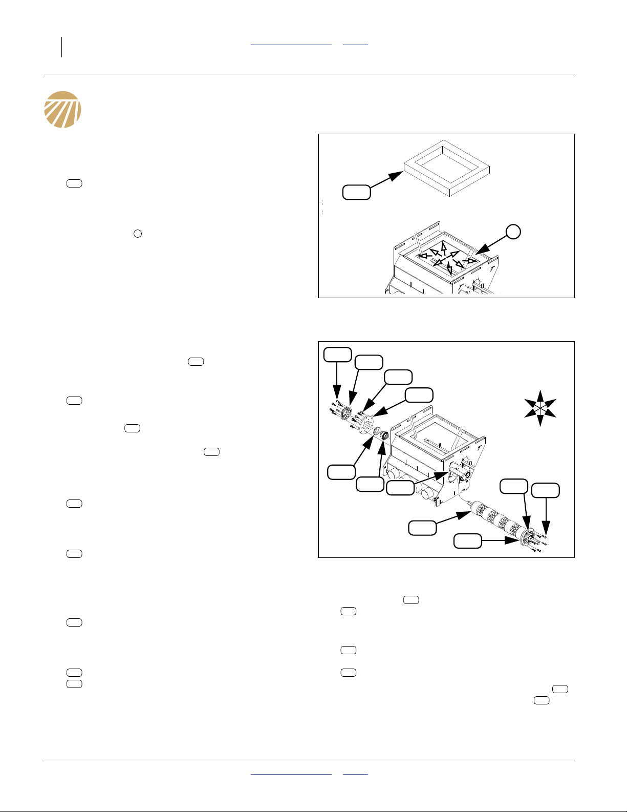
Remove Existing Top Seal
Refer to Figure 24
70. Remove the existing top seal:
220
816-662C METER TOP SEAL
This part is replaced by a new seal at step 104.
71. Prepare the top panel for welding and re-sealing.
Clean all top seal adhesive residue from the top
panel opening . If necessary, use sandpaper or
other abrasives.
72. Prepare the top panel for tack welding. Remove a
3
1cm(
way along each side of the top panel opening,
shown as small open arrows.
⁄8in) circle of paint at each corner, and half-
1
Remove Meter Flute Shaft
220
Figure 24
Meter Top Seal
1
Q0103
Refer to Figure 25
73. At the right end of the flute shaft, release the set
screw in the bearing collar .
74. At the left end of each meter, remove the six outer
screws:
163
801-151C SCR HEX SELF TAP 1/4-20X1TYPEF
These screws are not re-used.
Note: The plates is usually have a silicone sealant
bead around their circumference, and possibly on
the face. The bearing flange also has a silicone seal bead. Use a knife to cut the fillets, and a
sharp flat tool to pry components apart.
75. Withdraw and save the flute shaft assembly, one of:
125
166-308S 4-OUTLET METER 2-STAR SHFT ASY
166-320S 4-OUTLET METER 3-STAR SHFT ASY
166-321S 4-OUTLET METER 4-STAR SHFT ASY
76. Recover and save the sensor mount:
139
266-187D METER SENSOR MOUNT
131
134
231
Remove Old Flanges
77. At the right end of each meter, remove the six outer
screws:
163
801-151C SCR HEX SELF TAP 1/4-20X1TYPEF
These screws are not re-used.
78. Pry the flange assembly off the meter wall. Recover
and save one set:
134
188-009V BRG .755 HEX BORE W/S-S
218
816-199C SEAL 1.33IDX2.23ODX.31T
163
231
163
131
U
R
F
D
218
134
139
231
163
125
131
Figure 25
Meter Flute Shaft
79. At each plate , remove the six inner screws:
163
801-151C SCR HEX SELF TAP 1/4-20X1TYPEF
These screws are not re-used.
80. Separate (and save) bearing flange:
231
890-466C HSG RIBB FLG 6BOLT PLT
and mount plate (which is not saved):
131
168-409D METER SHAFT MOUNT PLATE
81. Clean the meter wall and both bearing flanges
of any silicone sealant residue. The plates are
not re-used and do not require cleaning.
131
Q0103
131
B
L
231
166-370M Table of Contents Index 05/25/2011
Page 21
Great Plains Manufacturing, Inc. Table of Contents Index Update Meters 17
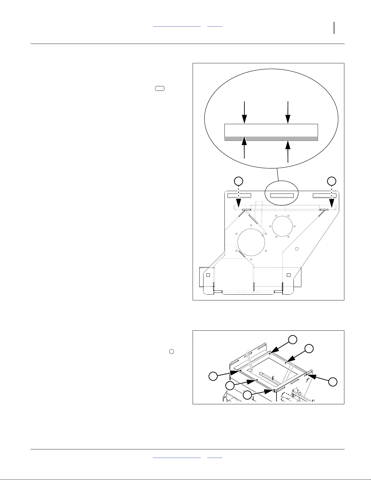
Enlarge Mounting Slots
Refer to Figure 26
The previous
with new1⁄2in (13 mm) bolts. The new mounts (not
shown) have 13.5 mm slots, but the existing slots in the
meter sidewalls do not. They need to be enlarged.
82. Use a cutting wheel, die grinder, or any suitable tool
to enlarge the six 10 mm slots to 13.5 mm.
Enlarge down (away from the top edge of the meter
sidewall). In the Figure, cut away the gray area.
3
⁄8in (9 mm) mounting bolts are replaced
919
Previously:
10 mm
(0.41 in.)
Enlarge to:
13.5 mm
(0.53 in.)
2 2
Figure 26
Mounting Slot Enlargement
Q0108
Drill Weep Holes
Refer to Figure 26 and Figure 27
83. Mark the meter top panel for six hole positions .
Each hole is to be 6 to 7 mm in diameter (1⁄4in). The
location needs to be clear of the existing outer
flange, and clear of the front and back meter faces
under the top panel (so that any future drainage is
outside the meter, and so that the weep holes do
not compromise air pressure control inside the
meter).
84. Drill and de-burr six holes.
05/25/2011 Table of Contents Index 166-370M
2
2
2
2
Figure 27
Top Panel Weep Holes
2
2
2
Q0103
Page 22
18 NTA607HD or NTA2007HD Table of Contents Index Great Plains Manufacturing, Inc.
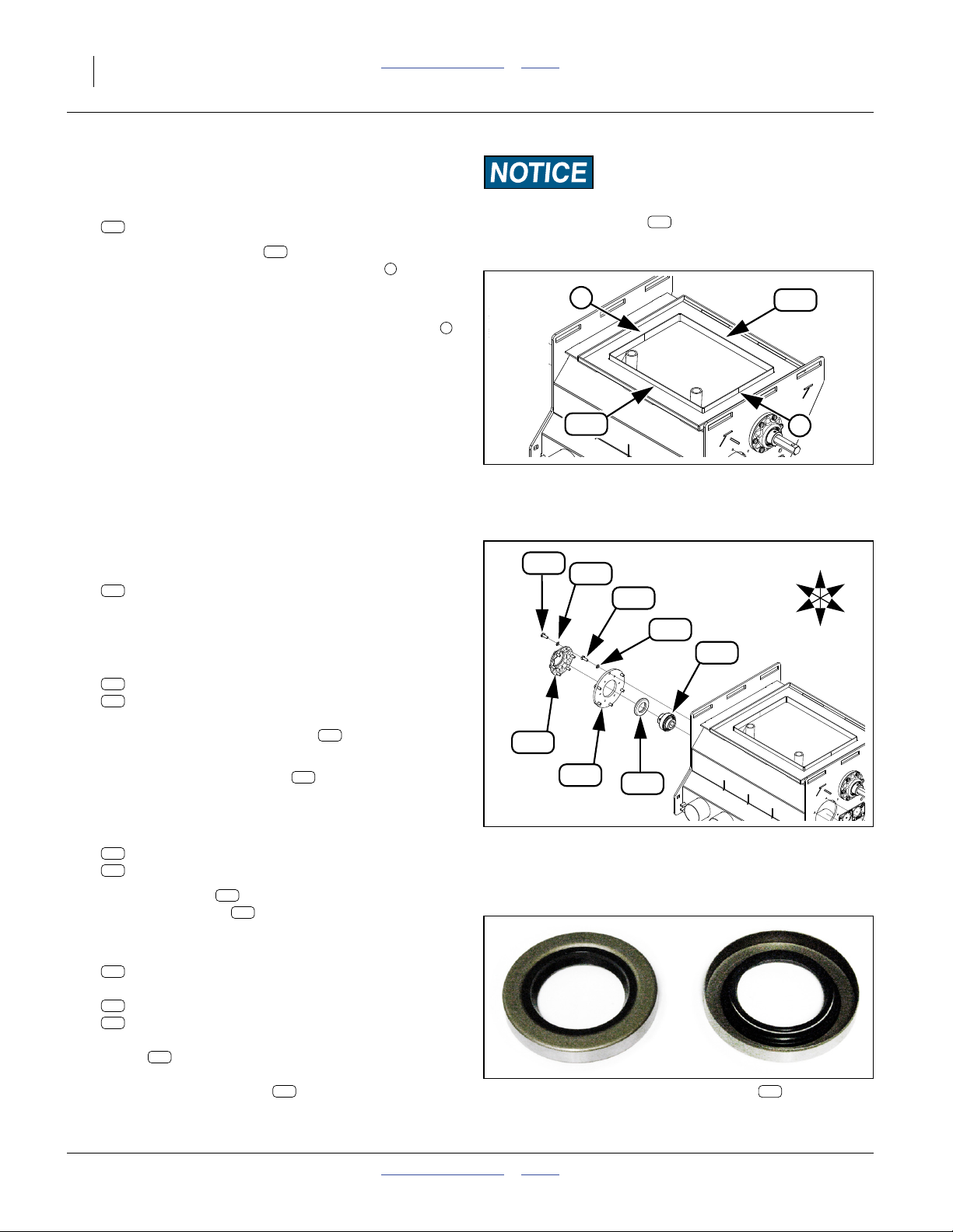
Install Meter Seal Flange
Refer to Figure 28 (new holes not shown)
85. For each meter, select two new:
924
266-306D METER SEAL FLANGE
86. Clamp the flange seals on the meter top panel,
around the opening. Make sure the ends of the
924
3
seals touch each other.
87. Tack weld the seal to the top panel at the corners,
halfway point on front and back, and at end joints .
88. Clean off any splatter or burned paint.
89. Allow the welds to cool.
90. Touch up bare/discolored areas with green enamel.
91. Allow paint to dry. Apply a bead of silicone sealant
to the inside corner of the top panel / seal flange
joint. Smooth the bead into a fillet shape.
Replace Meter Shaft Mount Plates
Replace Right End Plates
Refer to Figure 29
92. For each meter, select one new:
918
168-472D METER SHAFT MOUNT PLATE
Apply a bead of silicone sealant to one face of the
plate, in a circle around each outer bolt hole, and in
a circle on the outer bolt hole center-lines.
93. Select six sets new:
942
802-001C HHCS 1/4-20X3/4 SS
959
804-033C WASHER LOCK 1/4 SS
Apply silicone sealant under bolt heads and under
washer faces. Secure the plate to the right end
of the meter. Smooth excess sealant to fillet shape.
94. Select the saved flute shaft . Temporarily insert
the flute shaft from meter left.
Refer to Figure 30
95. Select one set saved:
134
188-009V BRG .755 HEX BORE W/S-S
218
816-199C SEAL 1.33IDX2.23ODX.31T
Add the bearing , with set screw collar to the
right. Add the seal with the solid face to the out-
134
218
side and the open face toward the meter.
96. Select one saved:
231
890-466C HSG RIBB FLG 6BOLT PLT
and six sets new:
942
802-001C HHCS 1/4-20X3/4 SS
959
804-033C WASHER LOCK 1/4 SS
Apply silicone sealant to the outer rim of the
flange . Place the flange over the bearing. Apply
231
silicone sealant under bolt heads and under washer
faces. Secure the flange to the right end of the
meter. Smooth any excess sealant into a fillet
shape.
918
125
231
Equipment Damage Risk:
Check that the flute shaft ( in Figure 25 on page 16) is
125
removed prior to welding. Slag and splatter can rapidly and
severely damage meter flutes and fillers.
3
3
924
Figure 28
Meter Seal Flange
942
959
942
959
134
231
918
Figure 30: 816-199C Seal
218
Figure 29
Right Shaft Mount Plate
218
Orientation: Outside / Inside
924
3
R
F
Q0103
U
B
L
D
Q0103
32122
166-370M Table of Contents Index 05/25/2011
Page 23
Great Plains Manufacturing, Inc. Table of Contents Index Update Meters 19
Replace Left End Plates
Refer to Figure 31
97. For each meter, select one new:
R
F
231
U
B
L
D
918
168-472D METER SHAFT MOUNT PLATE
one saved:
231
890-466C HSG RIBB FLG 6BOLT PLT
and six sets new:
942
802-001C HHCS 1/4-20X3/4 SS
959
804-033C WASHER LOCK 1/4 SS
98. Apply silicone sealant to the outer rim of the
flange , under bolt heads and under washer
faces. Secure the flange to the plate .
231
231 918
4
5
918
Smooth excess sealant to fillet shape.
99. Select one each saved:
125
166-308/20/21S 4-OUTLET STAR SHAFT ASY
139
266-187D METER SENSOR MOUNT
and one new:
977
816-693C AIR DRILL METER SHAFT GASKET
and six sets new:
942
802-001C HHCS 1/4-20X3/4 SS
959
804-033C WASHER LOCK 1/4 SS
100. Insert the shaft through the gasket , left wall
125 977
of meter, and bearing at right wall of meter.
101. Place lock washers on all bolts . Insert two
of the bolts through the sensor mount . The
sensor mount uses the top and top-front bolt
959 942
139
4 5
977
125
139
Figure 31
Left Shaft Mount Plate
959
942
Q0103
holes at the left meter wall.
102. Secure the plate to the left end of the meter with
942 959
bolts and lock washers .
918
Install New Top Seal
Refer to Figure 32
103. At each meter, clean and de-grease the top panel
6
in the area between the outer flange and the new
inner flange.
104. Select one new:
976
816-662C METER TOP SEAL
Before removing the release paper backing, make a
976
trial fit of the seal on the top panel.
105. Remove the backing paper. Bond the seal to
976
6
the top panel.
Figure 32
Q0103
Install Top Seal
05/25/2011 Table of Contents Index 166-370M
Page 24

20 NTA607HD or NTA2007HD Table of Contents Index Great Plains Manufacturing, Inc.
166-370M Table of Contents Index 05/25/2011
Page 25
Great Plains Manufacturing, Inc. Table of Contents Index 21
Update Cart
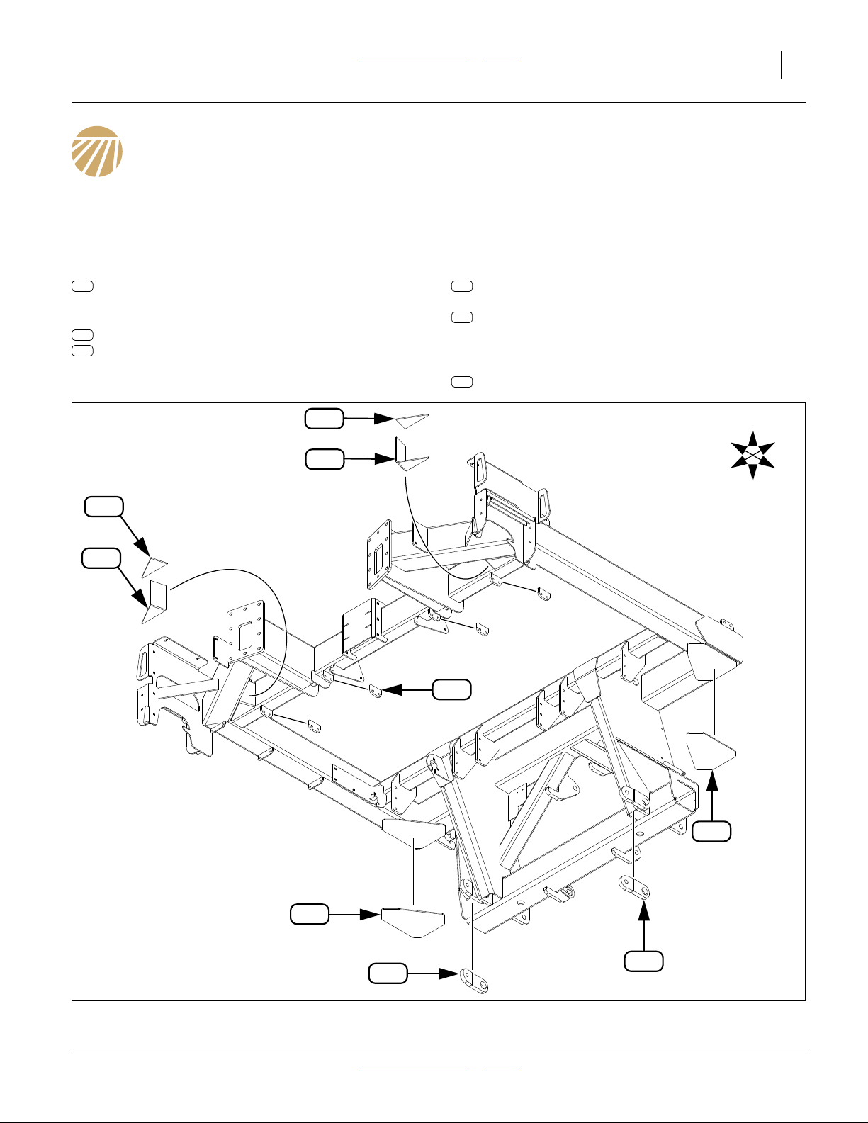
Cart Frame Update Overview
Twelve new parts are welded on the cart main frame,
and one on the tongue (not shown below):
Rear Gusset Plates (page 22)
Pull Bar Anchors (page 25)
925
266-307D REAR MAIN FRAME LAP GUSSET
Front Gusset Triangles (page 23)
926
266-308D FRONT MAIN FRAME CORNER GUSSET
927
266-309D FRNT MAIN FRAME CRNR CAP PLT
926
927
926
927
923
266-302D NTA2007 PULL BAR ANCHOR
A plate (not shown)
922
266-300D NTA2007 PULL BAR BOLT PLT
is also welded inside the tongue (page 24).
Meter Mount Tabs (page 27)
920
266-289D FRONT METER BOX MNT TAB
920
F
R
U
L
B
D
925
925
923
923
Figure 33
Cart Mainframe Update Weldments
05/25/2011 Table of Contents Index 166-370M
32124
Page 26
22 NTA607HD or NTA2007HD Table of Contents Index Great Plains Manufacturing, Inc.
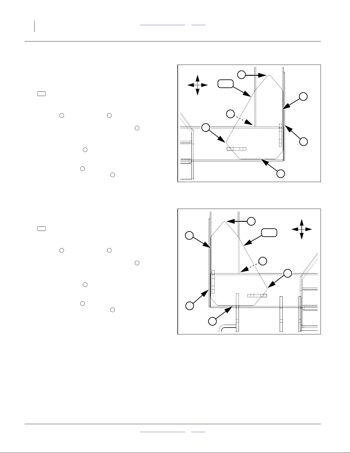
Install Rear Gussets
Install Left Rear Gusset
Refer to Figure 34
106. Select one new:
925
266-307D REAR MAIN FRAME LAP GUSSET
107. Roughly position the gusset on the bottom left rear
corner of the cart mainframe. Mark the frame using
the right and front edges of the gusset.
Remove the paint from the frame in these areas,
and long the inside edge of the corner .
108. Clamp the gusset on the frame.
Set the rear edge to slightly overlap the rounded
corner of the frame tube.
Set the left edge to provide a fillet space to the
existing outside gusset plate .
Tack weld in place.
109. Finish weld with a 6 mm (1⁄4in) fillet.
1 2
3
4
5
6
Install Right Rear Gusset
Refer to Figure 35
110. Select one new:
925
266-307D REAR MAIN FRAME LAP GUSSET
111. Roughly position the gusset on the bottom left rear
corner of the cart mainframe. Mark the frame using
the right and front edges of the gusset.
Remove the paint from the frame in these areas,
and long the inside edge of the corner .
112. Clamp the gusset on the frame.
1 2
3
R
F
925
L
B
2
5
3
1
6
4
Figure 34
Left Rear Gusset (from below)
32126
F
2
5
925
R
L
B
3
1
Set the rear edge to slightly overlap the rounded
corner of the frame tube.
Set the left edge to provide a fillet space to the
existing outside gusset plate .
Tack weld in place.
113. Finish weld with a 6 mm (1⁄4in) fillet.
114. Remove all slag and splatter. Clean and de-grease
all bare and discolored areas. Paint green.
166-370M Table of Contents Index 05/25/2011
4
5
6
6
4
Figure 35
Right Rear Gusset (from below)
32126
Page 27
Great Plains Manufacturing, Inc. Table of Contents Index Update Cart 23
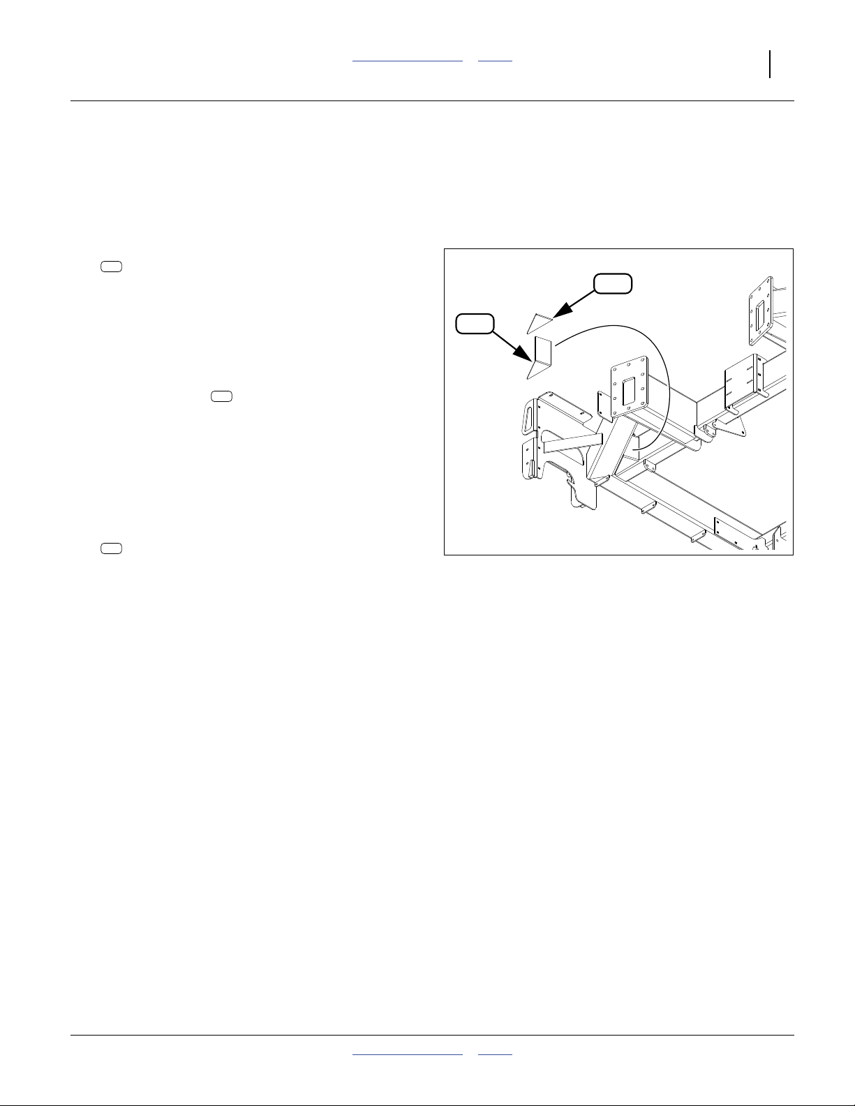
Install Front Gussets
Install Right Front Gusset
115. Remove the front reflector panels (if any) and walkboard to provide access.
Refer to Figure 36
116. Select one new:
927
266-309D FRNT MAIN FRAME CRNR CAP PLT
Note: Despite the “CAP” descriptor, this part is used as
the base of the new gusset structure.
117. Position this plate in the outer crevice of the front
outside tool bars. Mark the weld region along the
edges. Remove paint on the tubes in the weld
regions.
118. Position the plate fully into the crevice, with the
927
bottom triangle about 6 cm (1⁄4in) higher than the
bottom faces of the tube, and parallel with the tube
bottom faces. Tack weld in position.
119. Finish weld all around (inside and out), except near
the tip of the triangle (leave the tip unwelded to provide a weep/breather opening). Use at least a 6 cm
(1⁄4in) fillet.
120. Select one new:
926
266-308D FRONT MAIN FRAME CORNER GUSSET
121. Position this gusset at the top of the plate just
installed, fully into the crevice, and parallel to the top
of the adjacent tubes. Tack weld in position.
122. Finish weld all around.
Install Left Front Gusset
927
Right Front Gusset (from below)
926
Figure 36
32126
123. Repeat step 116 through step 122 for the left side.
124. Remove all slag and splatter. Clean and de-grease
all bare and discolored areas. Paint green.
Note: To ease access to fan hydraulics, walkboard
re-installation is deferred until step 184 on
page 32.
05/25/2011 Table of Contents Index 166-370M
Page 28
24 NTA607HD or NTA2007HD Table of Contents Index Great Plains Manufacturing, Inc.
Install Pull Bar Attach Points
Install Pull Bar Plate
Refer to Figure 37 and Figure 38
125. Remove the hitch casting from the tongue.
126. Remove the paint from the lower inside surfaces of
the front tongue side plates .
127. Select one new:
922
266-300D NTA2007 PULL BAR BOLT PLT
128. Position the plate for tack welding inside the tongue.
One method would be to place four 13 mm clamps
along the bottom edges of the hitch side plate. Rest
the bolt plate on the clamps. Check alignment.
129. Tack weld the bolt plate to the hitch plates. Finish
weld all around with a 13 mm (1⁄2in) fillet.
130. Remove all slag and splatter. Clean and de-grease.
Allow welds to cool.
131. Paint all bare and discolored surfaces of the bolt
plate and hitch side plates.
Note: Pull bars are installed at step 161 on page 28.
133
123
123
Figure 37
Plate and Pull Bars
123
133
922
Q0105
21.1°
922
13 mm
0.5 in
Figure 38
266-300D Plate Alignment
25.5 cm
10.04in
123
13 mm
0.5 in
Q0106
166-370M Table of Contents Index 05/25/2011
Page 29
Great Plains Manufacturing, Inc. Table of Contents Index Update Cart 25
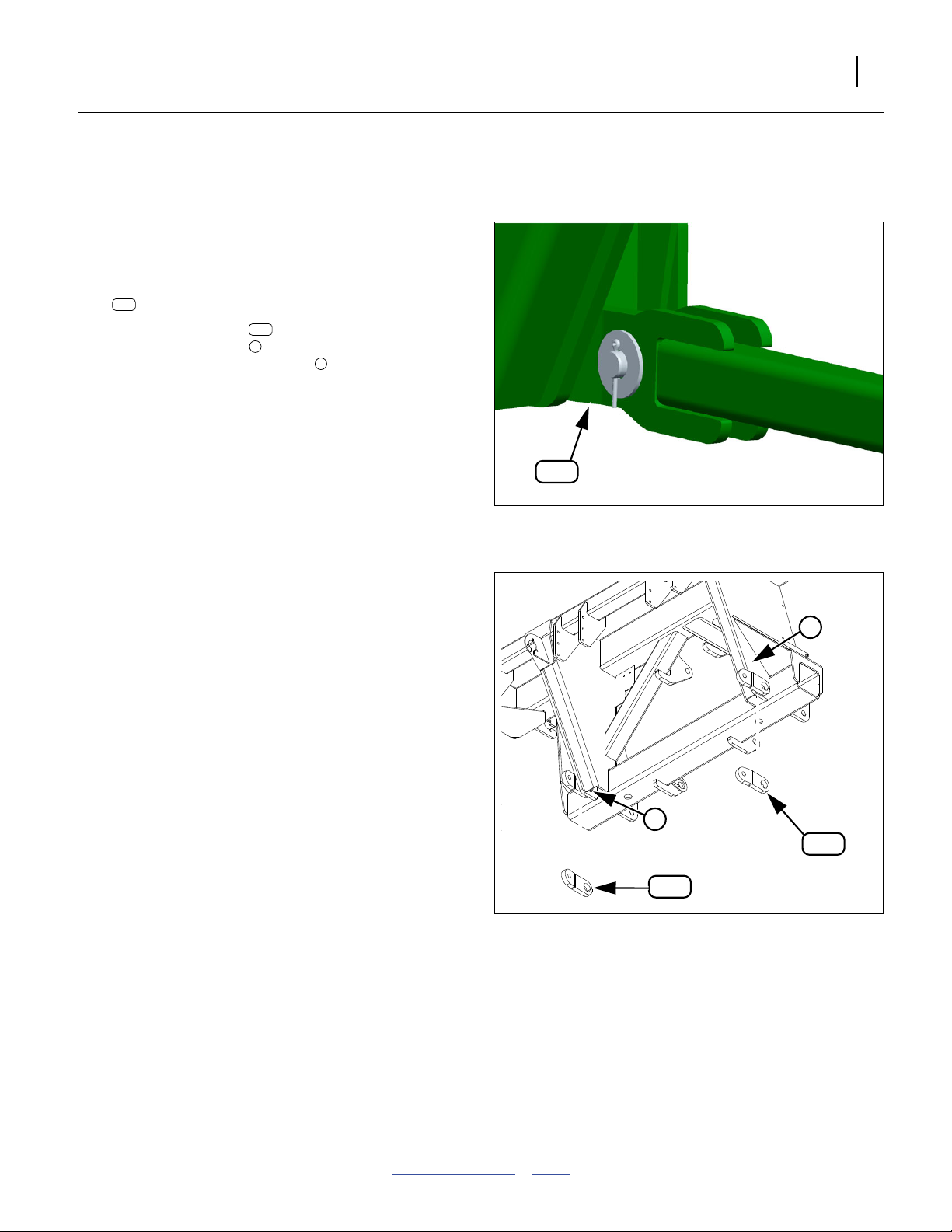
Install Pull Bar Anchors
Install Left Anchor
Refer to Figure 39 and Figure 40
132. Jack up the side of the cart sub-frame being worked
on. Dismount the wheel for access to the welding
site.
133. Select one new:
923
266-302D NTA2007 PULL BAR ANCHOR
134. Position the anchor on the outside (wheel side)
of the subframe leg , with the anchor’s larger hole
aligned with the existing hole in the leg plate.
135. Mark the left at the edges of the anchor. Remove
the paint from the leg in this weld region.
136. Make sure the break in the small-hole end of the
anchor is pointing forward and toward cart center,
with the lower edge parallel to the cart frame. The
break should be pointing directly at a hole on the
new hitch pull bar plate.
137. Clamp the anchor in this position. Tack weld.
138. Finish weld all around with a 13 mm (
It is not necessary to weld inside the large holes.
139. Remove all slag and splatter. Clean and de-grease
all bare and discolored areas. Paint green.
140. Re-mount the removed wheel.
Install Right Anchor
141. Repeat step 132 through step 140 for the right side.
923
7
8
923
Q0112
1
⁄2in) fillet.
Figure 39
Pull Bar Anchor Installed
7
8
923
923
Figure 40
Pull Bar Anchors (from below)
05/25/2011 Table of Contents Index 166-370M
32126
Page 30
26 NTA607HD or NTA2007HD Table of Contents Index Great Plains Manufacturing, Inc.
Update Meter Mounts
Position New Meter Mounts
The new meter mounts are temporarily installed to aid in
placement of the new front mount tabs.
Refer to Figure 41
142. Select four new:
919
266-288D METER BOX MOUNT
and six sets saved:
177
803-020C NUT HEX 1/2-13 PLT
187
804-015C WASHER LOCK SPRING 1/2 PLT
167
802-082C HHCS 1/2-13X1 3/4 GR5
143. Loosely attach each mount to a rear mount tab
1 6
( through ), as follows:
Right side of tab (for left meter)
Left side of tab (for left meter)
Right side of tab (for right meter)
Left side of tab (for right meter).
3 4
Tabs and (single center meter) are not used.
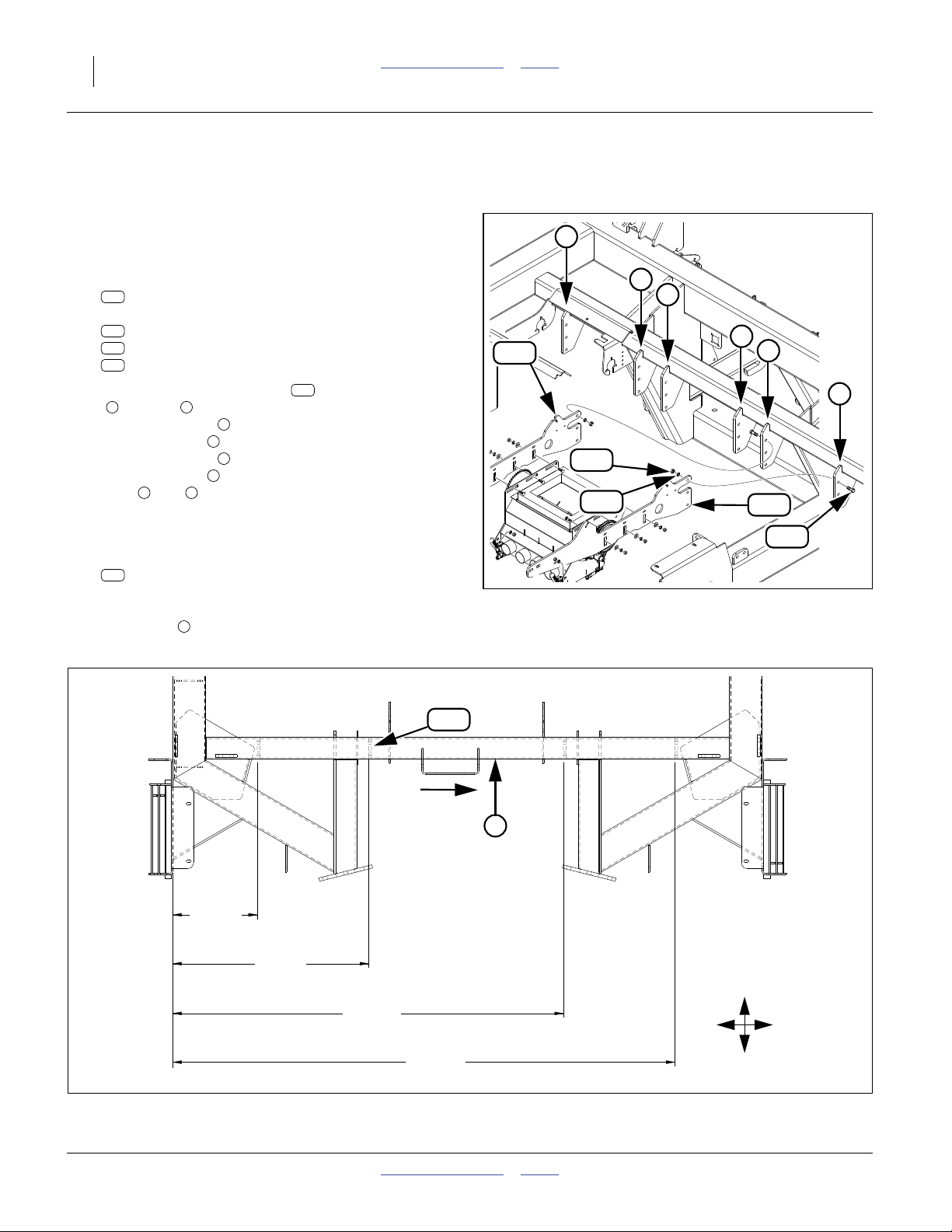
Prepare Tab Welding Sites
Refer to Figure 42
144. Select one new:
920
266-289D FRONT METER BOX MNT TAB
Use this tab to mark the general locations for tab
welding on the underside of the front cart
cross-tube . Remove the paint at these locations.
1
2
5
6
7
919
919
6
5
167
187
Figure 41
New Meter Mounts
4
3
2
1
919
177
32131
920
7
39.2 cm
15.44 in
90.9 cm
35.81 in
B
181.5 cm
71.44 in
233.3 cm
91.81 in
Figure 42
Front Meter Mount Tab Stations
166-370M Table of Contents Index 05/25/2011
R
L
F
32135
Page 31

Great Plains Manufacturing, Inc. Table of Contents Index Update Cart 27
Mark Tab Welding Sites
Refer to Figure 41 and Figure 42 on page 26
145. Select two sets new:
944
802-082C HHCS 1/2-13X1 3/4 GR5
950
803-020C NUT HEX 1/2-13 PLT
146. Using the bolts and nuts , loosely attach the
mounting tab at the front slots of a meter
mount , flat edge up, and on the same side of
919
944 950
920
the mount as the rear tab.
147. Consult the station layout in Figure 42. Re-mark
each station position precisely on the frame
cross-tube . Dimensions are from the right outside
7
face of the right frame tube to the tab right faces.
To measure to the face of a mount , add or subtract the thickness of the tab (12.7mm, 0.5in).
Use the meter mount as a check against posi-
919
919
7
tion errors. Each mount should be exactly perpendicular to the front cross-tube . Mark the tab side
edges on the cross-tube. Slide the tab to the center
7
920
of each mount slot. Mark the front and back edge
location on the cross-tube.
148. Repeat step 146 and step 147 for all four tabs.
Attach New Front Tabs
Refer to Figure 43
149. Remove two rear bolts from each meter mount .
919
Swing the mounts clear of the tab weld locations.
150. Select one new:
920
266-289D FRONT METER BOX MNT TAB
Clamp the tab at a weld location, flat side up against
frame cross-tube . Tack weld in position.
7
151. Finish weld all around, using a 9 mm (3⁄8in) fillet.
152. Remove weld slag and splatter.
153. Repeat step 150 through step 152 for all four tabs.
154. Paint the tabs, and all bare or discolored metal.
Install New Meter Mounts
Figure 43
Front Mount Tabs
919
944
32126
Wait for paint to dry. For each meter mount:
Refer to Figure 43 and Figure 44
155. Select two sets new:
944
802-082C HHCS 1/2-13X1 3/4 GR5
960
804-113C WASHER FLAT 1/2 USS HARD PLT
956
804-015C WASHER LOCK SPRING 1/2 PLT
950
803-020C NUT HEX 1/2-13 PLT
Swing the meter mount up against its new front
920
tab , on the same side of the tab as the rear tab.
156. Insert the bolts through the tab. Loosely add a
flat washer , lock washer and nut .
944
960 956 950
919
157. Re-install the rear tab fasteners removed at
960
956
950
Figure 44
New Meter Mounts
32131
step 149. Tighten all nuts to Grade 5 torque.
05/25/2011 Table of Contents Index 166-370M
Page 32

28 NTA607HD or NTA2007HD Table of Contents Index Great Plains Manufacturing, Inc.
Re-Install Meters
Meters are loosely re-installed, with final positioning after
hoppers are re-installed. For each meter:
Refer to Figure 45
158. Select one updated meter and six sets new:
945
802-106C RHSNB 1/2-13X1 1/2 GR5
960
804-113C WASHER FLAT 1/2 USS HARD PLT
956
804-015C WASHER LOCK SPRING 1/2 PLT
950
803-020C NUT HEX 1/2-13 PLT
159. With the meter in between the mounts ,
124 919
124
bring the meter sidewall slots into alignment with the
mount slots. Insert bolts from the meter side.
Add a flat washer , lock washer and nut ,
945
960 956 950
loosely secured (bolts at bottom of vertical slots).
Install Hopper Supports
921
956
960
945
950
921
124
Refer to Figure 45 (and Figure 53 on page 33)
160. Select four new:
921
266-290D LOWER HOPPER SUPPORT ANGLE
Insert the notched leg of the support angles into the
tab slots of the meter mounts . These are held
8
919
in place by the hoppers (installed starting on
page 33).
Install Pull Bars
Assemble Pull Bars
Refer to Figure 46
161. Select two sets:
916
166-368H NTA2007 PULL BAR
928
401-167H 16 ROW PULLBAR ADJUSTER
952
803-073C NUT HEX 1 1/2-6 PLT
Spin the jam nut well onto the adjuster .
Thread the adjuster a few full turns into the pull
916
bar .
162. Remove and save the end pin components:
967
805-412C PIN CLEVIS 1 X 4.13 USBL
949
803-007C NUT LOCK 1/4-20 PLT
929
402-011D SLEEVE, SPRING LINK MOUNT
946
802-152C HHCS 1/4-20X2 GR5
965
805-134C PIN CLEVIS 1 X 2 29/64 USABLE
958
804-028C WASHER FLAT 1 USS PLT
962
805-058C PIN COTTER 3/16 X 2
952 928
967
919
928
Figure 45
Hopper Supports
952
958
8
8
32131
949
929
946
916
965
962
Figure 46
Pull Bar Assembly & Parts ID
166-370M Table of Contents Index 05/25/2011
31098
Page 33

Great Plains Manufacturing, Inc. Table of Contents Index Update Cart 29
Attach Pull Bars
Refer to Figure 47
163. Select two sets:
967
805-412C PIN CLEVIS 1 X 4.13 USBL
958
804-028C WASHER FLAT 1 USS PLT
962
805-058C PIN COTTER 3/16 X 2
164. Bring the non-adjustable ends of the pull bars into
alignment with the anchors at the main wheels.
Secure with pin , washer and cotter .
967 958 962
923
958
967
Refer to Figure 48
165. At the hitch, adjust the turnbuckles until the adjuster
928 922
clevis holes align with the hole in the plate .
166. Select two sets:
965
805-134C PIN CLEVIS 1 X 2 29/64 USABLE
929
402-011D SLEEVE, SPRING LINK MOUNT
946
802-152C HHCS 1/4-20X2 GR5
949
803-007C NUT LOCK 1/4-20 PLT
Insert the pin from below. Add a sleeve ,
secure with bolt and lock nut .
167. With the jam nut still loose, tighten the
turnbuckle nut to a torque of:
965 929
946 949
952
8
136 N-m (100 foot-pounds)
168. Tighten the jam nut to just over Grade 2 torque:
952
1336 N-m (1000 foot-pounds)
923
962
Figure 47
Pull Bar on Anchor
946
952
Figure 48
Pull Bars on Plate
929
9
Q0112
949
922
928
Q0105
05/25/2011 Table of Contents Index 166-370M
Page 34

30 NTA607HD or NTA2007HD Table of Contents Index Great Plains Manufacturing, Inc.
Update Cart Hydraulics
This section splits the shared fan/fold hydraulic circuit
into separate dedicated circuits. Using the revised system requires an additional remote circuit on the tractor.
The figure below identifies affected existing components.
C
E
A
B
G
F
D
Note: This hydraulic update is optional. Do not update
the hydraulic system unless the tractor has an
available additional remote circuit.
211
210
213
223
209
207
161
209
210
161
214
228
Existing Parts
c/o Part Description
800-301C CABLE TIE 2 DIA MIN - YLW
161
810-345C VALVE 90 DEGREE SHUT-OFF
207
811-080C TE 3/4MJIC 3/4MORB 3/4MJIC
209
811-150C EL 3/4FJIC 3/4MJIC
210
811-195C HH1/2R1 028 3/4FJIC 3/4MORB
211
811-324C AD 3/4MORB 3/4FJIC
213
811-512C HH1/2R2 219 3/4FJIC 3/4MORB
214
841-002C AD 1 1/16MORB 3/4FORB
223
841-480C HH1/2R2 084 3/4FJIC 3/4MORB
228
G
F
E
D
C
B
A
Figure 49
Existing Cart Hydraulics
166-370M Table of Contents Index 05/25/2011
Q0107
Page 35

Great Plains Manufacturing, Inc. Table of Contents Index Update Cart 31
The figure below identifies new and re-routed existing
components.
169. Snake a fish line through the right tongue tube,
between hitch and near fan.
C
A
B
G
D
211
210
Note: The walkboard and left front reflector panel (if any)
are presumed to be still removed from the forward
gusset update on page 23.
E
F
G
F
E
D
C
B
A
971
209
937
936
937
214
936
978
Figure 50
Updated Cart Hydraulics
972
228
New Parts
c/o Part Description
800-301C CABLE TIE 2 DIA MIN - YLW
936
800-303C CABLE TIE 2 DIA MIN - BLK
937
811-394C CP 3/4FORB MALE QD POPPET TYPE
971
811-430C AD 3/4MJIC 3/4MJIC
972
841-555C HH1/2R2 156 3/4FJIC 3/4MORB
978
Q0132
05/25/2011 Table of Contents Index 166-370M
Page 36

32 NTA607HD or NTA2007HD Table of Contents Index Great Plains Manufacturing, Inc.
Route Dedicated Fold Hose
Refer to Figure 49 and Figure 50 on page 30 and 31
170. Select one new:
978
841-555C HH1/2R2 156 3/4FJIC 3/4MORB
With the MORB end forward (to hitch) and FJIC end
to the rear, pull this hose through the tongue tube
using the fish line.
171. Select four new:
936
800-301C CABLE TIE 2 DIA MIN - YLW
Secure two ties to each end of hose .
978
Mark Dedicated Fan Hose
172. Locate the (existing) fan supply hose . This hose
runs from the hitch to a tee at the fan shut-off
207
valve . This hose may be marked with two yellow
209
ties (or plain yellow tape). Pull on the hose from the
fan end to confirm its identity.
173. Remove any yellow ties or plain yellow tape from
the fan supply hose . Do not remove any printed
214
labels.
174. Select four new:
937
800-303C CABLE TIE 2 DIA MIN - BLK
Secure two ties to each end of the fan supply
214
hose .
175. Disconnect fan supply hose from the tee .
214 209
214
Re-Route Fold Hose
176. At the elbow connected to the inlet side of the
shut-off valve , disconnect the existing fold
228
hose (which runs to rear bulkhead Port F).
177. Select one new:
972
811-430C AD 3/4MJIC 3/4MJIC
Use this adaptor to join the ends of existing fold
228 978
hose to new fold hose .
210
207
Disconnect Bypass Hose
178. At the tee on the fan side of the shut-off
valve , disconnect the short spin-down loop
hose .
209
207
211
Re-Configure Inlet Fittings
179. Remove and disassemble all fittings at the fan inlet.
Removed items are, from motor to hoses:
223
841-002C AD 1 1/16MORB 3/4FORB
209
811-324C AD 3/4MORB 3/4FJIC
210
811-150C EL 3/4FJIC 3/4MJIC
209
811-080C TE 3/4MJIC 3/4MORB 3/4MJIC
207
810-345C VALVE 90 DEGREE SHUT-OFF
209
811-080C TE 3/4MJIC 3/4MORB 3/4MJIC
210
811-150C EL 3/4FJIC 3/4MJIC
Save the final 11⁄16in adaptor , one elbow
and one tee . The other fittings are not re-used.
209
223 210
See “Hydraulic Connectors and Torque” on page 70.
180. Select one each saved:
209
811-080C TE 3/4MJIC 3/4MORB 3/4MJIC
210
811-150C EL 3/4FJIC 3/4MJIC
Connect the elbow to the MJIC side port of the
209
tee , opposite the MORB port. When tightening,
210
align the MJIC end of the elbow to face in the same
direction as the center MJIC port of the tee.
181. Select one saved:
223
841-002C AD 1 1/16MORB 3/4FORB
Connect the MORB port of the tee to the FORB
end of the adaptor . Connect the MORB end of
the adaptor to the motor inlet. When tightening,
223
223
209
point the open MJIC fittings away from the motor,
and toward the hoses.
Re-connect Fan Hoses
182. Connect the short loop hose to the tee at
the motor inlet.
183. Connect the fan supply hose to the elbow at
the fan motor.
184. Re-install the walkboard and any removed reflectors.
211 209
214 210
166-370M Table of Contents Index 05/25/2011
Page 37

Great Plains Manufacturing, Inc. Table of Contents Index Update Cart 33
Re-Install Hoppers
Refer to Figure 51
185. Hoist the hopper sub-frame back into its original
position.
186. Select eight sets saved:
177
803-020C NUT HEX 1/2-13 PLT
187
804-015C WASHER LOCK SPRING 1/2 PLT
188
804-017C WASHER FLAT 1/2 USS PLT
167
802-082C HHCS 1/2-13X1 3/4 GR5
Secure the hopper sub-frame to the cart frame.
Align Meters
Refer to Figure 52
187. Raise each meter until the foam seal contacts
the hopper flange.
188. Adjust the front-to-rear position of the meter until
the meter inlet is centered under the hopper opening.
Check that the hopper vent structure tubes
mate with the vent tubes (not shown) in the meters.
189. Raise the meter another 1 to 2 cm (0.4 to 0.8 in.) to
partially compress the seal, providing an air-tight
connection.
Refer to Figure 53
190. Tighten the six nuts at the meter mounts.
950
976
127
127
Figure 51
Re-Mount Hoppers
Figure 52
Vent Alignment
Q0102
950
Q0111
950
Figure 53
Q0110
Hopper on Updated Meter
05/25/2011 Table of Contents Index 166-370M
Page 38

34 NTA607HD or NTA2007HD Table of Contents Index Great Plains Manufacturing, Inc.
Re-Install Final Drive Chain
Refer to Figure 54
191. At the right end of each meter, re-mount the
102 129
chain on the meter input gear . Engage the
final drive idlers .
221
129
221
102
Re-Connect Inlets/Outlets
Refer to Figure 55 (which has the inlet manifold removed for
clarity)
192. Re-connect the meter inlet elbows and primary
outlet hoses (not shown). Secure with saved
clamps.
219
Re-Install Gears
193. Re-install saved final drive gears ( and ).
Secure the driving gear with a saved pin .
130 204
198
Re-Install Sensors
194. Place the speed sensor on the driven shaft.
Secure with saved pin . Tighten thumbscrew.
195. Re-attach the anti-rotation strap to the sensor
mount .
Refer to Figure 56
196. At each hopper, re-connect the hopper level sensor
lead to the air cart harness .
139
146 151
145
198
219
Figure 54
Install Final Drive Chain
130
204
160
139
Figure 55
Meter Elbows, Sensor, Gears
Q0033
198
145
Q0109
151
146
Figure 56
Hopper Level Sensor Lead
166-370M Table of Contents Index 05/25/2011
Q0101
Page 39

Great Plains Manufacturing, Inc. Table of Contents Index Update Cart 35
Update Hopper Lids
Refer to Figure 57
For each hopper:
197. Unlatch the lid. At the crossbar -to-lid connection, remove and save the nut and bolt:
181
803-147C NUT HEX NYLOCK 1/2-13
171
802-130C HHCS 1/2-13X2 1/2 GR5
198. Swing the crossbar up to relieve tension in the
128
existing spring assembly. At the crossbar-toswivel connection, remove and save the pivot
126
nut and bolt:
181
803-147C NUT HEX NYLOCK 1/2-13
171
802-130C HHCS 1/2-13X2 1/2 GR5
Remove the arm for further updating.
Leave the swivel in place.
126
199. Remove the existing spring assembly from the
crossbar :
176
186
203
166
128
803-014C NUT HEX 3/8-16 PLT
804-013C WASHER LOCK SPRING 3/8 PLT
807-268C SPRING COMP DIE.75X.375X1.50L
802-017C HHCS 3/8-16X1 GR5
These parts are not re-used.
Refer to Figure 57 and Figure 58
200. Select one each new:
941
801-235C SCR HX SKT BUT CP 3/8-16X2 1/2
968
807-268C SPRING COMP DIE.75X.375X1.50L
and three new:
955
804-012C WASHER FLAT 3/8 SAE PLT
Place the new spring , then the three
washers , onto the bolt .
955 941
968
201. Select the saved:
128
167-283D BIN LID TOP CROSS BAR
and one new:
953
803-078C NUT LOCK 3/8-16 NYLON INSERT
Insert the bolt/spring/washer assembly through the
larger hole on the top of the crossbar , then
through the smaller bottom hole. Add the lock
953
nut . Secure just enough to remove any play
from the spring assembly. No pre-compression of
the spring is required.
202. Select one set saved:
181
803-147C NUT HEX NYLOCK 1/2-13
171
802-130C HHCS 1/2-13X2 1/2 GR5
Angle the crossbar up to allow the bar and
swivel pivot holes to align. Insert bolt . Secure
with lock nut .
128
2
181
203. Select the other set saved:
181
803-147C NUT HEX NYLOCK 1/2-13
171
802-130C HHCS 1/2-13X2 1/2 GR5
Re-attach the crossbar to the hopper lid. Close and
latch lid.
This completes the cart update.
128
1
128
171
181
128
181
Figure 57
Hopper Lid Existing Hardware
941
126
968
2
Figure 58
Hopper Lid Spring Update
171
2
1
955
953
126
171
128
167
Q0111
32137
05/25/2011 Table of Contents Index 166-370M
Page 40

36 NTA607HD or NTA2007HD Table of Contents Index Great Plains Manufacturing, Inc.
Update Implement Frame
Dismount Lift-Assist
Disconnect Lights
Refer to Figure 59 (depicting NTA607HD lighting)
204. Disconnect the lighting harness at both rear
lights. Check that at least one leg of the cable is
marked “LEFT” or “RIGHT”. If not, apply a marking.
205. Remove the harness from the lighting structures,
support tubes and lift-assist parallel arms. This may
require releasing clips or even dismounting support
tubes. Coil the harness up at the rear of the main
frame.
206. Recover and save any clips on the pull link .
Pinch / Crush Hazards:
Follow support and hoisting instructions carefully. Removing
the lift-assist requires disconnecting large heavy parts that are
mutually supporting. Unsupported parts can swing or fall at
disconnection, which could result in serious injury or death.
222
107
222
222
Figure 59
Rear Lighting Harness
107
Q0080
Release Lift Link
Refer to Figure 60
207. Verify that there is no tension in the lift link .
If the front pull link was removed (step 54 on
page 12), the rear clevis should be easy to remove.
208. Remove and save one each:
196
805-117C PIN ROLL 1/4 X 2 1/2 PLT
194
804-117C WASHER FLAT 1/4 HARD ASTMF436
then remove the pin:
118
160-781D PIN 1 1/2 X 4 USABLE 1045
(which has a second washer and roll pin )
194 196
113
113
118
Figure 60
Rear Lift Link
196
194
Q0122
166-370M Table of Contents Index 05/25/2011
Page 41

Great Plains Manufacturing, Inc. Table of Contents Index Update Implement Frame 37
Dismount Parallel Arms
Refer to Figure 61
209. Support the lift-assist cross-tube . Once the
upper parallel arms are removed, it can tip away
from the wheels. The combined assembly weighs
nearly 450 kg (1000 pounds).
210. At the parallel arms , remove and save four:
200
805-255C PIN ROLL 3/8 X 2 1/2 PLT
105
and eight:
193
804-039C WASHER FLAT 1 1/4 SAE PLT
108
193
104
105
200
211. Remove and save four:
104
160-201H WING PIVOT PIN WELDMENT
and two:
105
160-314H REAR PARALLEL LIFT LINK WELDMT
Remove Pull Link
212. Support the rear end of the pull link . With rear
111
pins removed, the link is free to swing down and
forward. The link weighs 150 kg (330 pounds).
213. Remove and save two sets:
200
805-255C PIN ROLL 3/8 X 2 1/2 PLT
111
160-324H PIN WLDMNT 1.25 X 12.34 NR
then remove and save the lift-assist .
214. Attach a hoist to the link . Remove and save two:
200
805-255C PIN ROLL 3/8 X 2 1/2 PLT
107
and six:
193
804-039C WASHER FLAT 1 1/4 SAE PLT
215. Remove and save two:
104
160-201H WING PIVOT PIN WELDMENT
then remove the pull link:
107
160-316H NTA607HD REAR PULL LINK WELDMT
The pull link is not re-used.
107
108
107
111
200
Figure 61
Dismount Lift-Assist
108
Q0115
Update Rear Link Anti-Rotation
Refer to Figure 62 (which depicts the pull link connected this is not done until step 311 on page 52)
216. Select two new:
904
160-795D PIN RETAINER TAB
and two saved:
104
160-201H WING PIVOT PIN WELDMENT
Position these at the lower outside pivot holes of the
LH and RH main frame rear. Mark around the outer
edges of the tabs . Remove the paint from the
904
main frame weldment in preparation for welding.
217. Tack weld the tabs to the main frame. Remove
and save the pins .
904
104
218. Finish weld around the outside (only) of the
904
tabs , fillet of 7 mm (1⁄4in.) fillet.
219. Clean off all weld splatter and slag. Allow the welds
to cool. Paint green.
05/25/2011 Table of Contents Index 166-370M
904
104
Figure 62
Rear Lift Link
Q0123
Page 42

38 NTA607HD or NTA2007HD Table of Contents Index Great Plains Manufacturing, Inc.
Update Wing Pivot Anti-Rotation
Refer to Figure 63
If the existing pins are undamaged, leave the wing pivot
104
pins in place for this update.
Pinch / Crush Hazard:
If the existing pins must be removed, follow instructions carefully. Remove only one pin at a time. Begin inserting a second
pin before the first is fully removed. Without use of additional
hoists and supports, an un-pinned wing can move or fall,
which could result in injury and equipment damage.
Start with the LH rear pivot.
220. If the existing pin is undamaged, continue at
104
step 223.
221. At the damaged pin , remove and save one:
200
805-255C PIN ROLL 3/8 X 2 1/2 PLT
104
222. Select two new:
901
160-201H WING PIVOT PIN WELDMENT
Use one of the new pins to drive the old pin
out. Then use the second new pin to drive the
first new pin back out, with this second new pin
901
901 104
901
replacing the damaged old pin as originally
installed.
223. Select one new:
915
160-811D WING HINGE PIN ROTATION STOP
224. Place the stop around the pivot shaft cap of the
new or existing pin ( or ). On the pivot extension, mark around the outer edge of the stop for
915
901 104
915
paint removal. Remove paint in preparation for
welding.
225. Tack weld the stop, at the outer edges only.
226. Finish weld the stop, fillet of 7 mm (1⁄4in.) fillet.
227. Clean off all weld splatter and slag. Allow the welds
to cool. Paint green.
228. Repeat step 220 through step 227 for the LH front,
and RH wing pivot pins.
915
Figure 63
Wing Pivot Anti-Rotation
104
901
Q0124
166-370M Table of Contents Index 05/25/2011
Page 43

Great Plains Manufacturing, Inc. Table of Contents Index Update Implement Frame 39
Update Wing Pivot Extension Tops
Update Front Extension Tops
Start with the LH side. Remove and replace only the top
fasteners. Leave the cross-bolt and lower fasteners in
place.
Refer to Figure 64
229. Remove two sets:
179
803-027C NUT HEX 3/4-10 PLT
190
804-023C WASHER LOCK SPRING 3/4 PLT
174
802-910C RHSNB 3/4-10 X 2 GR5 PLT
Save the washers . The bolts and nuts
190 174 179
are not re-used.
Refer to Figure 65 (which depicts the new square nuts
951
installed - this is not done until step 235)
230. Select one each new:
912
160-808D FRAME EXT 100 DEG GUSSET
914
160-810D FR EXT 100 DEG GUSSET REWORK
The shorter gusset to the front. The longer
gusset is to the wing inside.
914
912
231. Position the gussets. Slide them as far toward the
pivot extensions as allowed by the existing weld fillets. Keep them in full contact with existing gussets.
Mark the wing for paint removal at all accessible
corners and joints of each gusset. Remove paint in
preparation for welding.
232. Tack weld the gussets in position.
233. Finish weld all around each gusset, using an
8mm(5⁄16in) fillet. Keep the weld fillet small at the
joint plates, so that it won’t interfere with the new
square nuts .
951
234. Clean off all weld splatter and slag. Paint the welded
area green.
235. Select two sets new:
943
802-064C HHCS 3/4-10X2 GR5
951
803-047C NUT SQ 3/4-10 PLT
and two saved:
190
804-023C WASHER LOCK SPRING 3/4 PLT
Add a lock washer to each bolt . Position the
square nuts on the wing side of the joint plates.
190 943
951
Insert the bolts through the joint plates, from the
wing extension side, and thread into bolts. Tighten
bolts to Grade 5 torque specification.
236. Repeat step 229 through step 235 for the right wing
front.
Existing Top Front Hardware
943
LH Wing Top Front Gussets
Note: The new square nuts are NOT welded (or
tack-welded) onto the wing frame.
190
912
174
Figure 64
Figure 65
951
951
190
179
Q0116
914
Q0126
05/25/2011 Table of Contents Index 166-370M
Page 44

40 NTA607HD or NTA2007HD Table of Contents Index Great Plains Manufacturing, Inc.
Update Rear Extension Tops
Refer to Figure 66
237. Remove two sets:
179
803-027C NUT HEX 3/4-10 PLT
190
804-023C WASHER LOCK SPRING 3/4 PLT
174
802-910C RHSNB 3/4-10 X 2 GR5 PLT
Save the washers . The bolts and nuts
190 174 179
are not re-used.
Refer to Figure 67 (which depicts the new square nuts
951
installed - this is not done until step 243)
238. Select one each new:
912
160-808D FRAME EXT 100 DEG GUSSET
913
160-809D FR EXT 100 DEG GUSSET REWORK
The longer gusset to the front. The shorter
gusset is to the wing inside.
912
913
239. Position the gussets. Slide them as far toward the
pivot extensions as allowed by the existing weld fillets. Keep them in full contact with existing gussets.
Mark the wing for paint removal at all accessible
corners and joints of each gusset. Remove paint in
preparation for welding.
240. Tack weld the gussets in position.
241. Finish weld all around each gusset, using an
8mm(5⁄16in) fillet. Keep the weld fillet small at the
joint plates, so that it won’t interfere with the new
square nuts .
951
242. Clean off all weld splatter and slag. Paint the welded
area green.
243. Select two sets new:
943
802-064C HHCS 3/4-10X2 GR5
951
803-047C NUT SQ 3/4-10 PLT
and two saved:
190
804-023C WASHER LOCK SPRING 3/4 PLT
Add a lock washer to each bolt . Position the
square nuts on the wing side of the joint plates.
190 943
951
Insert the bolts through the joint plates, from the
wing extension side, and thread into bolts. Tighten
bolts to Grade 5 torque specification.
244. Repeat step 237 through step 243 for the right wing
front.
This completes welded updates.
245. Re-connect any hoses or cables removed for weld
protection.
Existing Top Rear Hardware
912
LH Wing Top Rear Gussets
Note: The new square nuts are NOT welded (or
even tack-welded) onto the wing frame.
174
Figure 66
951
Figure 67
951
190
913
190
943
179
Q0116
Q0124
166-370M Table of Contents Index 05/25/2011
Page 45

Great Plains Manufacturing, Inc. Table of Contents Index 41
Update Harness
Dismount Existing Harnesses
Although all of the existing harness components are
re-used, it is both simpler and faster to completely
remove them, and then re-install them. Start at Tower H
on the right wing.
Refer to Figure 68 and Figure 69
246. Locate, remove and save the CANbus terminator:
149
467980126 MINI CAN TERMINATOR
There is only one of these. This component is connected to one lead of a row harness , which is
plugged into a WSMB (Working Set MemBer).
152
148
247. At the WSMB, disconnect and save the row harnesses:
148
467751330S1 16 ROW HARNESS
Disconnect row harness leads from the blockage sensors , and from the WSMB harness .
147 153
148
248. Disconnect save any sensor lead extensions, which
may be one of (not shown in Figures):
142
457901815 DJ HARNESS 10 FT EXT 3 PIN WP
143
459680920 EXT. HARNESS 3’, FAN RPM
144
459680922 EXT. HARNESS 15’ FAN RPM
Leave the blockage sensors installed.
249. Dismount and save the WSMB
152
467981100S1 INTAG WSMB MODULE 18R
Save the following fasteners where encountered:
175
803-006C NUT HEX 1/4-20 PLT
183
804-006C WASHER LOCK SPRING 1/4 PLT
173
802-370C HHCS 1/4-20X1 3/4 GR5
Where WSMBs are mounted with1⁄4-20 hex head
cap screws shorter than 13⁄4in (4.4 cm), these do
not need to be saved.
The WSMB harness:
153
467981201A INT AG HARNESS, WSMB MODULE
may be left connected to the WSMB.
Refer to Figure 70
250. Dismount the WSMB mounting brackets (except at
implement weights, where the cross-bar mount
120
may be left in place). Save all:
177
803-020C NUT HEX 1/2-13 PLT
187
804-015C WASHER LOCK SPRING 1/2 PLT
201
806-010C U-BOLT 1/2-13X21/2X31/2
If the U-bolt is also securing the tower tube to its
mount, leave it in place. The bracket used to mount
the WSMB is not re-used.
251. Disconnect, dismount and save any CANbus extension cable to the next WSMB to the left (not shown
in Figures):
150
467980141 10’ EXT HARNESS
CANbus
Power
177
CANbus
Data
Figure 68
CANbus and Terminator
152
120
148
Figure 69
WSMB and Harness at Weights
187
Figure 70
Tower Mounting Near Center
149
28429
147
Q0082
201
Q0127
05/25/2011 Table of Contents Index 166-370M
Page 46

42 NTA607HD or NTA2007HD Table of Contents Index Great Plains Manufacturing, Inc.
252. Working from right to left along the implement, disconnect, dismount and save all WSMBs , row
harnesses , and sensor lead extensions ( ,
143 144
,).
148 142
152
154
Refer to Figure 71
At Towers B-G, also remove and save any CANbus
extensions . At Tower A, do not remove the
CANbus extension from the POM (Planter
150
150 154
Output Module).
253. Sort the removed harness components into groups
by part number.
Enumerate WSMBs
To ease configuration and operation of the
DICKEY-john®IntelliAg® console, install the WSMBs in
serial number order. This causes the initial automatic
sensor-to-row assignments to be correct by default.
Refer to Figure 72
254. Select one new:
934
467981100S1 INTAG WSMB MODULE 18R
Apply some tape, and label this WSMB “6”. As a
new module, it should have a serial number higher
than any installed modules. (If any WSMBs on this
air drill have ever been replaced, check that the new
WSMB is indeed the highest number.)
255. Select all of the saved:
152
Sort them in order of serial number . Label them,
in ascending serial number order as “1” through “5”.
Separately record the serial numbers and applied
ID numbers (for use at step 392 on page 67).
934
467981100S1 INTAG WSMB MODULE 18R
7
Figure 71
POM at Implement Center
7
6
Figure 72
152 934
, WSMB-18R
32147
31434
166-370M Table of Contents Index 05/25/2011
Page 47

Great Plains Manufacturing, Inc. Table of Contents Index Update Harness 43
Install WSMBs
Mount Center WSMBs
Mount Tower B WSMB
Refer to Figure 73
256. Select one new:
917
166-988D BRACKET, 45DEG MODULE MOUNT
and one saved:
201
806-010C U-BOLT 1/2-13X21/2X31/2
and two sets saved (not shown):
187
804-015C WASHER LOCK SPRING 1/2 PLT
177
803-020C NUT HEX 1/2-13 PLT
Install the bracket behind Tower B (left center
917
seed tower), just above and parallel to the angle
that secures both towers to each other. Orient the
WSMB mounting face to the outside and forward.
Secure to tower with U-bolt , lock washers
and nuts . To avoid crushing the tower tube,
177
201 187
tighten only to Grade 2 torque specification.
257. Select the saved WSMB tagged as “2”:
152
467981100S1 INTAG WSMB MODULE 18R
and two sets new or saved:
175
803-006C NUT HEX 1/4-20 PLT
183 954
173 947
Install WSMB on the outside (wing side) of the
bracket , with the connector ports facing down
and to implement rear. Insert bolts ( or )
804-006C WASHER LOCK SPRING 1/4 PLT
802-370C HHCS 1/4-20X1 3/4 GR5
#2
917
173 947
through the WSMB and bracket. Secure with lock
washers ( or ) and nuts .
183 954 175
Mount Tower C WSMB
Refer to Figure 74
258. Select one new:
917
166-988D BRACKET, 45DEG MODULE MOUNT
and one saved:
201
806-010C U-BOLT 1/2-13X21/2X31/2
and two sets saved (not shown):
187
804-015C WASHER LOCK SPRING 1/2 PLT
177
803-020C NUT HEX 1/2-13 PLT
Install the bracket behind Tower C (right center
917
seed tower), just above and parallel to the angle
that secures both towers to each other. Orient the
WSMB mounting face to the outside and forward.
Secure to tower with U-bolt , lock washers
and nuts . To avoid crushing the tower tube,
177
201 187
tighten only to Grade 2 torque specification.
259. Select the saved WSMB tagged as “5”:
152
467981100S1 INTAG WSMB MODULE 18R
and two sets new or saved:
175
803-006C NUT HEX 1/4-20 PLT
183 954
173 947
804-006C WASHER LOCK SPRING 1/4 PLT
802-370C HHCS 1/4-20X1 3/4 GR5
119
119
201
183
152
947
Install WSMB on the outside (wing side) of the
bracket , with the connector ports facing down and to
implement rear. Insert bolts ( or ) through the
WSMB and bracket. Secure with lock
washers ( or ) and nuts
917
183 954 175
B
175
954
Figure 73: Tower B
WSMB#2 Mounting
G
#5
173
119
Figure 74 Tower C
WSMB#5 Mounting
#5
917
917
173 947
F
C
954
152
173
119
175
183
#2
947
Q0125
201
Q0125
05/25/2011 Table of Contents Index 166-370M
Page 48

44 NTA607HD or NTA2007HD Table of Contents Index Great Plains Manufacturing, Inc.
Mount Wing WSMBs
Mount Tower A (Left Wing) WSMBs
Refer to Figure 75
260. Select one new:
917
166-988D BRACKET, 45DEG MODULE MOUNT
and one saved:
201
806-010C U-BOLT 1/2-13X21/2X31/2
and two sets saved (not shown):
187
804-015C WASHER LOCK SPRING 1/2 PLT
177
803-020C NUT HEX 1/2-13 PLT
Install the bracket behind Tower A (left wing
917
seed tower), just above and parallel to the angle
that secures both towers to each other. Orient the
WSMB mounting face to the inside and rear. Secure
to tower with U-bolt , lock washers and
177
nuts . To avoid crushing the tower tube, tighten
201 187
only to Grade 2 torque specification.
261. Select the saved WSMBs tagged as “1” and “4”:
152
467981100S1 INTAG WSMB MODULE 18R
and two sets new or saved:
175
803-006C NUT HEX 1/4-20 PLT
183 954
173 947
Install WSMB on the front face and WSMB on
the rear face of the bracket , with the connector
804-006C WASHER LOCK SPRING 1/4 PLT
802-370C HHCS 1/4-20X1 3/4 GR5
#1 #4
917
ports facing down and to implement center. Insert
173 947
bolts ( or ) through either WSMB, bracket
and other WSMB. Secure with lock
washers ( or ) and nuts .
183 954 175
Mount Tower D (Right Wing) WSMBs
Refer to Figure 74
262. Select one new:
917
166-988D BRACKET, 45DEG MODULE MOUNT
and one saved:
201
806-010C U-BOLT 1/2-13X21/2X31/2
and two sets saved (not shown):
187
804-015C WASHER LOCK SPRING 1/2 PLT
177
803-020C NUT HEX 1/2-13 PLT
Install the bracket inside Tower D (right wing
917
seed tower), just above and parallel to the angle
that secures both towers to each other. Orient the
WSMB mounting face to the inside and rear. Secure
to tower with U-bolt , lock washers and
177
nuts . To avoid crushing the tower tube, tighten
201 187
only to Grade 2 torque specification.
263. Select the saved WSMB tagged as “5”:
152
467981100S1 INTAG WSMB MODULE 18R
and the new WSMB:
934
467981100S1 INTAG WSMB MODULE 18R
and two sets new or saved:
175
803-006C NUT HEX 1/4-20 PLT
183 954
173 947
804-006C WASHER LOCK SPRING 1/4 PLT
802-370C HHCS 1/4-20X1 3/4 GR5
119
119
152
201
917
119
#6 934
Install WSMB on the front face and WSMB on the
rear face of the bracket , with the connector ports facing down and to implement center. Insert
173 947
bolts ( or ) through either WSMB, bracket and
other WSMB. Secure with lock washers ( or ) and
175
nuts .
A
#1
E
173 947
Figure 75: Tower A
WSMB#1, WSMB #4 Mounting
D
H
#3
917
173947
Figure 76: Tower D
WSMB#3, WSMB #6 Mounting
#3 #6
917
119
183 954
#4152
Q0124
152
201
Q0124
166-370M Table of Contents Index 05/25/2011
Page 49

Great Plains Manufacturing, Inc. Table of Contents Index Update Harness 45
Install Row Harnesses
Refer to Figure 77, Figure 78 (which is part of the full
harness diagram found on page 88 and 89)
Connector ID
Group
a
b
c
d
e
a. Not all pin locations may be populated.
Harness connections are shaped, sized, polarized,
keyed and color-coded to prevent mis-configuration.
Each WSMB harness has eight connectors, which can
be confusing. Familiarity can save time.
These instructions have you install and completely connect one row harness at a time. Row harness leads
are labelled 1-16 on every harness. Having multiple
leads with the same numbers nearby can lead to mis-connection.
Type (on
Cable)
4-pin plug
a
plug
6-pin
4-pin receptacle
a
receptacle
6-pin
dual 12-pin
receptacle
dual 12-pin
plug
3-pin
148
Function
Upstream CANbus power
Upstream CANbus data
Downstream CANbus power
Downstream CANbus data
WSMB
Local function
(sensor harness in this case)
Connection to each
blockage sensor
148
147
e
152
d
a
153
Figure 77
WSMB and Row Harness
c
b
32149
05/25/2011 Table of Contents Index 166-370M
Page 50

46 NTA607HD or NTA2007HD Table of Contents Index Great Plains Manufacturing, Inc.
Connect WSMB #1
Refer to Figure 77 (on page 45) and Figure 78 (which is part
of the full harness diagram found on page 88 and 89)
264. If WSMB (on Tower A) does not have a WSMB
harness connected, select one saved:
153
Connect the 12-pin receptacle leads into
WSMB .
265. Connect the 4/6-pin CANbus plug leads into the
4/6-pin CANbus receptacle leads of the existing
467980141 extension harness from the POM
(not shown) at implement center.
266. Select a saved:
148
267. Connect the WSMB’s 12-pin plug leads into the
12-pin receptacle leads of the row harness .
268. Use cable ties to secure the row harness core to
To we r A .
269. Select two saved 3m (10ft) extensions:
142
connect these to harness sensor leads 11 and 12.
270. Connect the 3-pin sensor leads or extensions to
their respective seed row blockage sensors, per the
chart on page 86 and the diagram on page 88.
271. Select four new (not shown):
932
Cap the ends of the four unused harness leads
(leads 13 to 16, also not shown).
#1
467981201A INT AG HARNESS, WSMB MODULE
c
#1
152
a
b
150
467751330S1 16 ROW HARNESS
d
148
457901815 DJ HARNESS 10 FT EXT 3 PIN WP
e
464211090 DUST PLUG
150
b b
a
WSMB
1
152
A
d
4 Leads
Unused
153
WSMB
c
148
e
467751330S1
4
4 Leads
142
Unused
e
e
Figure 78: Tower A
WSMB #1 Connections
166-370M Table of Contents Index 05/25/2011
Q0118
Page 51

Great Plains Manufacturing, Inc. Table of Contents Index Update Harness 47
S
Connect WSMB #4
Refer to Figure 79 (on page 45) and Figure 79 (which is part
of the full harness diagram found on page 88 and 89)
272. If WSMB (on Tower A) does not have a WSMB
#4
harness connected, select one saved:
153
467981201A INT AG HARNESS, WSMB MODULE
Connect the 12-pin receptacle leads into
#4
WSMB .
152
273. Connect the 4/6-pin CANbus plug leads into the
4/6-pin CANbus receptacle leads of the
467981201A WSMB harness from WSMB .
153
c
a
b
#1
153
b
MB
1
274. Select a saved:
148
467751330S1 16 ROW HARNESS
275. Connect the WSMB’s 12-pin plug leads into the
12-pin receptacle leads of the row harness .
d
148
276. Use cable ties to secure the row harness core to
To we r E .
277. Select two saved 3m (10ft) extensions:
142
457901815 DJ HARNESS 10 FT EXT 3 PIN WP
Connect these to harness sensor leads 11 and 12.
278. Connect the 3-pin sensor leads or extensions to
e
their respective fertilizer row blockage sensors, per
the chart on page 87 and the diagram on page 88.
The rows requiring extensions are off the illustration
at right - see page 89.
279. Select four new (not shown):
932
464211090 DUST PLUG
Cap the ends of the four unused harness leads
(leads 13 to 16, also not shown).
280. Select one saved:
150
467980141 10’ EXT HARNESS
Connect the plug end of this harness to the
receptacle end of the WSMB harness .
b#4
a
153
Route the cable toward Tower B. Route the cable at
the left wing pivot so that it passes through pivot
centerline, and has just enough slack for wing folding.
153
a
WSMB
c
148
467751330S1
e
b
A
4
E
4 Leads
150
a
152
142
d
Unused
e
Figure 79: Tower A/E
Q0118
WSMB #4 Connections
05/25/2011 Table of Contents Index 166-370M
Page 52

48 NTA607HD or NTA2007HD Table of Contents Index Great Plains Manufacturing, Inc.
Connect WSMB #2
Refer to Figure 77 (on page 45) and Figure 80 (which is part
of the full harness diagram found on page 88 and 89)
281. If WSMB (on Tower B) does not have a WSMB
harness connected, select one saved:
153
Connect the 12-pin receptacle leads into
WSMB .
282. Connect the 4/6-pin CANbus plug leads into the
4/6-pin CANbus receptacle leads of the
467980141 extension harness from WSMB .
283. Select a saved:
148
284. Connect the WSMB’s 12-pin plug leads into the
12-pin receptacle leads of the row harness .
285. Use cable ties to secure the row harness core to
To we r B .
286. Select eight saved 91 cm (3ft) extensions:
143
Connect these to harness sensor leads
9 through 16.
287. Connect the 3-pin sensor leads or extensions to
their respective seed row blockage sensors, per the
chart on page 86 and the diagram on page 88.
#2
467981201A INT AG HARNESS, WSMB MODULE
c
#2
152
a
b
150
467751330S1 16 ROW HARNESS
d
148
459680920 EXT. HARNESS 3’, FAN RPM
e
#4
150
152
B
WSMB
148
B
2
153
b
b
a
c
d
e
e
166-370M Table of Contents Index 05/25/2011
143
Figure 80: Tower B
WSMB #2 Connections
Q0118
Page 53

Great Plains Manufacturing, Inc. Table of Contents Index Update Harness 49
Connect WSMB #5
Refer to Figure 77 (on page 45) and Figure 81 (which is part
of the full harness diagram found on page 88 and 89)
288. If WSMB (on Tower C) does not have a WSMB
harness connected, select one saved:
153
Connect the 12-pin receptacle leads into
WSMB .
289. Connect the 4/6-pin CANbus plug leads into the
4/6-pin CANbus receptacle leads of the
467981201A WSMB harness from WSMB .
290. Select a saved:
148
291. Connect the WSMB’s 12-pin plug leads into the
12-pin receptacle leads of the row harness .
292. Use cable ties to secure the row harness core to
To we r G .
293. Select eight new 91 cm (3ft) extensions:
931
Connect these to harness sensor leads
9 through 16.
294. Connect the 3-pin sensor leads or extensions to
their respective fertilizer row blockage sensors, per
the chart on page 87 and the diagram on page 89.
The rows requiring extensions are off the illustration
at right - see page 89.
295. Select one saved:
150
Connect the plug end of this harness to the
receptacle end of the WSMB harness .
Route the cable toward Tower B. Route the cable at
the right wing pivot so that it passes through pivot
centerline, and has just enough slack for wing folding.
#5
467981201A INT AG HARNESS, WSMB MODULE
c
#5
152
a
b
153
467751330S1 16 ROW HARNESS
459680920 EXT. HARNESS 3’, FAN RPM
e
467980141 10’ EXT HARNESS
a
b#5
#2
d
148
153
153
b
153
150
a
a
b
C
WSMB
5
152
c
G
d
148
e
931
e
Figure 81: Tower C/G
WSMB #5 Connections
05/25/2011 Table of Contents Index 166-370M
Q0118
Page 54

50 NTA607HD or NTA2007HD Table of Contents Index Great Plains Manufacturing, Inc.
Connect WSMB #3
Refer to Figure 77 (on page 45) and Figure 78 (which is part
of the full harness diagram found on page 88 and 89)
296. If WSMB (on Tower D) does not have a WSMB
harness connected, select one saved:
153
Connect the 12-pin receptacle leads into
WSMB .
297. Connect the 4/6-pin CANbus plug leads into the
4/6-pin CANbus receptacle leads of the
467980141 extension harness from WSMB .
298. Select a saved:
148
299. Connect the WSMB’s 12-pin plug leads into the
12-pin receptacle leads of the row harness .
300. Use cable ties to secure the row harness core to
To we r D.
301. Select two saved 4.6 m (15ft) extensions:
144
Connect these to harness sensor leads 1 and 2.
302. Connect the 3-pin sensor leads or extensions to
their respective seed row blockage sensors, per the
chart on page 86 and the diagram on page 89. The
rows requiring extensions are off the illustration at
right - see page 89.
303. Select four new (not shown):
932
Cap the ends of the four unused harness leads
(leads 13 to 16, also not shown).
#3
467981201A INT AG HARNESS, WSMB MODULE
c
#3
152
a
b
150
467751330S1 16 ROW HARNESS
d
148
459680922 EXT. HARNESS 15’ FAN RPM
e
464211090 DUST PLUG
#5
WSMB
5
150
144
e
153
b
b
a
WSMB
3
c
D
d
4 Leads
Unused
467751330S1
e
Figure 82: Tower D
WSMB #3 Connections
166-370M Table of Contents Index 05/25/2011
Q0118
Page 55

Great Plains Manufacturing, Inc. Table of Contents Index Update Harness 51
Connect New WSMB #6
Refer to Figure 77 (on page 45) and Figure 83 (which is part
of the full harness diagram found on page 88 and 89)
304. Select one new:
935
467981201A INT AG HARNESS, WSMB MODULE
Connect the 12-pin receptacle leads into
WSMB .
305. Select one saved:
149
Plug this component into the 6-pin receptacle
lead of the WSMB harness.
Note: The final 4-pin power connector is not terminated.
306. Select one new:
933
Connect the WSMB’s 12-pin plug leads into the
12-pin receptacle leads of the row harness .
307. Use cable ties to secure the row harness core to
To we r H .
308. Select two saved 4.6 m (15ft) extensions:
144
Connect these to harness sensor leads 1 and 2.
309. Connect the 3-pin sensor leads or extensions to
their respective fertilizer row blockage sensors, per
the chart on page 87 and the diagram on page 89.
310. Secure all harness routings with cable ties.
#6
467980126 MINI CAN TERMINATOR
b
467751320S1 DJ 12 ROW HARNESS
459680922 EXT. HARNESS 15’ FAN RPM
c
d
933
e
150
b
144
E
153
a
WSMB
3
935
b
a
b
WSMB
6
(New)
149
c
934
H
d
e
933
e
e
Figure 83: Tower H
WSMB #6 Connections
Q0118
05/25/2011 Table of Contents Index 166-370M
Page 56

52 NTA607HD or NTA2007HD Table of Contents Index Great Plains Manufacturing, Inc.
Install Rear Pull Link
Pin Link to Main Frame
Refer to Figure 84
311. Connect a hoist to the new:
903
160-316H NTA607HD REAR PULL LINK WELDMT
The lug is down after installation. The weldment
may be shipped on a pallet with the lug up.
312. Select two saved:
104
160-201H WING PIVOT PIN WELDMENT
313. Hoist the link into alignment with the implement
main frame. Insert pins to secure.
903
104
314. Select two saved:
200
805-255C PIN ROLL 3/8 X 2 1/2 PLT
and six:
193
804-039C WASHER FLAT 1 1/4 SAE PLT
Place the washers on the pins just installed.
Secure with roll pins .
193 104
200
Connect Lift-Assist Link
Refer to Figure 85
315. Select one saved:
118
160-781D PIN 1 1/2 X 4 USABLE 1045
and two sets saved:
196
805-117C PIN ROLL 1/4 X 2 1/2 PLT
194
804-117C WASHER FLAT 1/4 HARD ASTMF436
316. Bring the lift link clevis into alignment with the
pull link lug. Connect with pin . Secure pin with a
washer and roll pin on each end.
194 196
113
118
113
193
200
104
903
Figure 84
Install New Rear Pull Link
194
118
Q0115
196
Figure 85
Q0122
Re-Connect Rear Lift Link
166-370M Table of Contents Index 05/25/2011
Page 57

Great Plains Manufacturing, Inc. Table of Contents Index Install Rear Pull Link 53
Connect Lift Assist
Refer to Figure 86
317. Select two saved:
111
160-324H PIN WLDMNT 1.25 X 12.34 NR
318. Connect a hoist to the saved:
108
160-317H NTA607HD LIFT ASST FRAME WLMT
Bring the lower front lugs of the lift-assist
weldment into alignment with the rear pivot
tubes of the new pull link . Insert pins .
319. Select two saved:
200
Drive roll pins into lower pin weldments .
108
903 111
805-255C PIN ROLL 3/8 X 2 1/2 PLT
200 111
104
193
105
200
Re-Install Parallel Arms
Refer to Figure 86
320. Select two saved:
105
160-314H REAR PARALLEL LIFT LINK WELDMT
and four saved:
104
160-201H WING PIVOT PIN WELDMENT
Pin the parallel arm tubes to the main frame in front,
and to the upper front lugs of the lift-assist weldment at rear.
Note: Set the lift switch whisker above the arm tube.
321. Select eight saved:
193
804-039C WASHER FLAT 1 1/4 SAE PLT
and four saved:
200
805-255C PIN ROLL 3/8 X 2 1/2 PLT
Add three washers to each forward pin , and
one washer to each rear pin . Secure weldment
104 200
pins with roll pins .
193 104
104
903
200
111
Figure 86
Connect Lift-Assist
104
108
Q0115
Re-Connect Lights
Refer to Figure 87 (depicting NTA607HD)
322. Re-route the lighting harness dismounted at
step 204 on page 36. Connect each leg of the “Y” to
its respective luminaire. Secure the harness with
any clips saved at step 206.
222
222
Figure 87
Re-Route Lighting Harness
05/25/2011 Table of Contents Index 166-370M
Q0080
Page 58

54 NTA607HD or NTA2007HD Table of Contents Index Great Plains Manufacturing, Inc.
Update Implement Hydraulics
Extend Valve Hoses
The weight transfer valve group is relocated to improve
visibility from the tractor cab. Extend hoses prior to valve
relocation. Extend hoses one at a time to eliminate the
need to mark hoses or trace routes. See “Hydraulic
Connectors and Torque” on page 70.
Refer to Figure 88
323. Select one set new:
972
811-430C AD 3/4MJIC 3/4MJIC
974
811-831C HH1/2R2 034 3/4FJIC
Open the3⁄4in connection at . Insert the new
974 972
hose and adaptor .
3
324. Select four sets new:
970
811-315C AD 9/16MJIC
973
811-701C HH3/8R2 033 9/16FJIC
One at a time, open a5⁄16in connection at . Insert
a new hose and adaptor . Of the five new
973 970
9
hoses, three are clamped to the wing near the pivots. Route these under any existing hoses (see
Figure 90 on page 55).
High Pressure Fluid Hazard:
Wear gloves and eye protection. Open (“crack”) hydraulic
connections slowly. Even with the systems set to Float prior to
unhitching, there may still be residual pressure in some lines. if
an injury occurs, seek immediate attention from a physician
familiar with this type of injury.
9
9
9
3
Relocate Valve Group
Refer to Figure 89
325. Remove and save two sets:
178
803-021C NUT HEX 5/8-11 PLT
189
804-022C WASHER LOCK SPRING 5/8 PLT
and one:
202
806-105C U-BOLT 5/8-11X41/32X6
326. Relocate the valve group:
114
160-331S NTA607HD HYDRAULIC VALVE ASY
further outboard on the wing. The new U-bolt
center-line is approximately 3.8 cm (1.5 in) inboard
of the inside rear face of the wing gauge wheel
1
plate . Secure valve group with saved U-bolt ,
lock washers and nuts .
189 178
327. Remove or obscure the existing operating decals:
229
848-504C DECAL WING DOWN PRESSURE PIC
230
848-505C DECAL FRAME BACK PRESSURE PIC
328. Clean and dry the top surface of the wing tool bar
on either side of the relocated valve group.
329. Select one each new:
979
848-504C DECAL WING DOWN PRESSURE PIC
980
848-505C DECAL FRAME BACK PRESSURE PIC
Apply 848-505C to the left of the valve group. Apply
848-504C to the right. Apply to the top or front of the
tool bar left of the group. Apply to the top or front of
the tool bar at right, or to the inside face of the
gauge wheel mount (clear of lock channel storage).
202
178
9
Figure 88
Existing Valve Group Hoses
114
230
229
189
202
Figure 89
Weight Transfer Valves
Q0128
1
Q0053
166-370M Table of Contents Index 05/25/2011
Page 59

Great Plains Manufacturing, Inc. Table of Contents Index Update Implement Hydraulics 55
Protect Hose Extensions
Refer to Figure 90
330. Select one new:
975
816-480C HOSE WRAP 3.0-4.5 X 24LG VELCR
and three new:
938
800-035C CABLE TIE .31X28 8DIA 120LB
975
Close the wrap on itself around the three hoses
975
clamped to the wing. Adjust the wrap position so
that the ends are across the front-to-rear wing tube
near the wing extensions, and across the next frontto-rear rib toward the outside.
Fold the wrap around itself. Secure it with the ties.
Figure 90
Hose Wrap
32163
05/25/2011 Table of Contents Index 166-370M
Page 60

56 NTA607HD or NTA2007HD Table of Contents Index Great Plains Manufacturing, Inc.
166-370M Table of Contents Index 05/25/2011
Page 61

Great Plains Manufacturing, Inc. Table of Contents Index 57
Re-Hitch Implement
Install Front Pull Link
Pinch / Crush Hazards:
Use an adequate hoist or lifter. Use three or more lines. Place
lines where they cannot slip. The weldment weighs over
902
270 kg (600 pounds).
Refer to Figure 91
331. Select one new:
902
160-315H NTA607HD FRONT PULL LINK WLDMT
Attach a hoist.
332. Select two saved:
104
160-201H WING PIVOT PIN WELDMENT
Hoist the pull link into alignment with the implement main frame. Insert pins .
902
104
333. Select two sets saved:
193
804-039C WASHER FLAT 1 1/4 SAE PLT
200
805-255C PIN ROLL 3/8 X 2 1/2 PLT
Place the washers on the weldment pins .
Secure with poll pins . Leave the hoist attached
193 104
200
to the pull link.
Re-Connect Lift Link
Refer to Figure 92
334. Select one saved:
118
160-781D PIN 1 1/2 X 4 USABLE 1045
with its two sets of:
194
804-117C WASHER FLAT 1/4 HARD ASTMF436
196
805-117C PIN ROLL 1/4 X 2 1/2 PLT
Remove one washer and roll pin.
335. Use the hoist to bring the top lug of the pull link
into alignment with the front clevis of the lift link .
Insert the pin . Add a washer . Secure with
roll pin .
336. Check the length of the lift link . Adjust the rear
118 194
196
112
clevis turnbuckle as needed to obtain a length,
clevis center-line to clevis center-line of:
202.0 cm (7917⁄32in)
Note: Although the hoist could be disconnected from the
pull link at this time, it may be useful for implementcart hitching.
902
112
196
104
Figure 91
Install New Front Pull Link
902
112
118
194
Figure 92
Connect Lift-Assist Link
193
200
902
31238
196
194
31423
05/25/2011 Table of Contents Index 166-370M
Page 62

58 NTA607HD or NTA2007HD Table of Contents Index Great Plains Manufacturing, Inc.
Connect Cart and Implement
Refer to Figure 93
337. Select two saved:
110
160-323H PIN WLDMNT 1.25 X 15.66 NR
338. Bring the cart arm lugs into alignment with the
front pivot tubes of the new pull link . From the
inside of the two inner cart lugs, insert the weldment
110
pins .
339. Select two saved:
200
805-255C PIN ROLL 3/8 X 2 1/2 PLT
Secure the weldment pins with roll pins .
1
902
110 200
110
200
1
110
200
902
Re-Install Link Components
Refer to Figure 94
340. On the new pull link , install all clamps, clips,
brackets and their fasteners removed at step 47 on
page 11. This might include:
155
502-068D HYD HOSE CLAMP BRACKET
156
800-052C HOSE CLIP 5/8 I.D.
158
800-064C HOSE CLIP 13/16 ID
164
802-007C HHCS 5/16-18X3/4 GR5
165
802-012C HHCS 5/16-18X1 1/2 GR5
169
802-115C HHCS 5/16-18X2 GR5
184
804-009C WASHER LOCK SPRING 5/16 PLT
plus the:
116
160-760D TRANSPORT LOCK PIN 1 X 8.25
117
160-763D NTA607HD PIN STORAGE BRACKET
Secure bolts loosely, as hoses and harnesses need
to be routed.
Store Spacers
341. Store the existing spacer set:
208
810-442C MW STOP BUSH SET 1 1/4 SBS125
on the wire loops of the new pull link.
Store New Lift Pins
Refer to Figure 94
342. Select two new:
966
805-306C HITCH PIN 1X3 1/4 W/COTTER
Store each these in the lug holes provided.
902
165
158
169
184
Figure 93
Hitch Cart to Pull Link
184
156
155
156
155
158
Figure 94
Clamp Re-Installation
117
155
966
116
184
31422
164
208
31238
166-370M Table of Contents Index 05/25/2011
Page 63

Great Plains Manufacturing, Inc. Table of Contents Index Re-Hitch Implement 59
Re-Install Link Lift Cylinders
Refer to Figure 95
343. Select two sets saved:
115
160-754D NTA607 PULL LINK CYLINDER LUG
199
805-187C PIN CLEVIS 1 X 2 1/4 GR5 PLT
195
805-104C PIN COTTER 3/16 X 1 1/2 PLT
199 115
Pin the narrow end of each lug in the rear
holes of the pull link lugs. Secure pin with
195
cotter .
344. Select the saved lift cylinders:
205
810-170C CYL REP 3.5X10X1.25 ROD (TIE)
199
195
205
197
141
and four sets saved:
197
805-124C PIN CLEVIS 1 X 3 11/16 GR5 PLT
141
2A0132 MW PIN CLIP
Orient the cylinders with the hydraulic fittings facing
up. Connect the base ends to the upper holes of the
main frame plates. Connect the rod ends to the lugs
installed at step 343. Secure pins with clips.
115
205
Re-Install Weight Transfer Cylinders
Refer to Figure 96
345. Select the saved weight transfer cylinder
206
810-219C CYL 3.5X16X2 ROD (TIE ROD)
that has the transfer solenoid valve . This is the
right hand cylinder.
346. Orient the hydraulic fittings to center. Connect the
base end to the upper cart lug using the saved:
140
2A0206 MW PIN SHORT
141
2A0132 MW PIN CLIP
347. Connect the rod end to the back pressure flex
109
link using the saved:
141
2A0132 MW PIN CLIP
197
805-124C PIN CLEVIS 1 X 3 11/16 GR5 PLT
348. Select the other saved weight transfer cylinder:
206
810-219C CYL 3.5X16X2 ROD (TIE ROD)
and the saved pins and clips. Orient the hydraulic
fitting to center. Connect the base end of the cylinder to the upper cart lug. Connect the rod end to the
back pressure flex link . Secure pins with clips.
109
2
109
140
Figure 95
Install Link Lift Cylinders
206
Figure 96
Install Weight Transfer Cylinders
31238
141
2
140
Q0047
05/25/2011 Table of Contents Index 166-370M
Page 64

60 NTA607HD or NTA2007HD Table of Contents Index Great Plains Manufacturing, Inc.
Route Hoses and Harnesses
Legend:
212-227 Part Number
C01-C05 hose Clamp
E, F, G cart ports
H Harness
L Lights
M Markers
S lift Switch
a. See manual 113-850M for
marker hose installation
a
226
Facing Rear
H
M
L
M
S
C03
H
F
G
E
225
224
L
M
224
H
C02
Facing Rear
L,S
M
226
C01
M
216
224
Facing Right
M
212
226
Facing Rear
C04
217
Facing Down
226224
227
215
C05
Figure 97
Cart-Implement Hydraulic Hose Routing
166-370M Table of Contents Index 05/25/2011
Q0067(4), 31273,
Q0068
Page 65

Great Plains Manufacturing, Inc. Table of Contents Index Re-Hitch Implement 61
Refer to Figure 97 on page 60, and the table at right
349. Route hydraulic hoses and harnesses through clips
and under clamps on new pull link.
Connect Hoses and Harnesses
Refer to Figure 98
350. At the bulkhead at the left rear of the cart, plug in all
hydraulic hoses and cables. Some cable connects
may not be at the bulkhead.
Hose ID for Pull Link Clamping
c/o Part No. Descriptor
212 811-291C HH1/2R2 072 3/4FJIC
215 811-617C HH1/2R2 140 3/4FJIC
216 811-665C HH1/2R2 208 3/4FJIC
217 811-785C HH1/2R2 168 3/4FJIC
224 841-162C HH3/8R2 184 3/4MORB 9/16FJIC
225 841-189C HH3/8R2 074 3/4MORB 9/16FJIC
226 841-451C HH1/2R2 148 3/4FJIC 3/4MORB
227 841-452C HH3/8R2 138 9/16FJIC
A Marker (option)
B Marker (option)
C Implement Lower
D Implement Lift
E Lock/Fold
F Unfold/Transfer
G SUMP
Figure 98
Cart Bulkhead Ports
848-526C
05/25/2011 Table of Contents Index 166-370M
Page 66

62 NTA607HD or NTA2007HD Table of Contents Index Great Plains Manufacturing, Inc.
Update Markers
If markers are not installed on this air drill, continue at
“Update Coulters” on page 65.
Start with the left marker.
Remove Tension Spring
Refer to Figure 99
351. At the marker tension spring , loosen the lower
jam nut . Disconnect the spring from the spring
holder . Leave the top jam nut undisturbed, so
that at re-installation, the spring tension remains at
the current setting.
Note: See the drill Operator manual for adjusting spring
178
238
tension.
239
239
232
178
238
Release Swing Pivot
Refer to Figure 100
352. Remove and save one set:
182
803-342C NUT HEX TOP LOCK 1/2-13 PLT
171
802-130C HHCS 1/2-13X2 1/2 GR5
238
SFM-8666 HAUKAAS SPRING HOLDER SFM
Release Cylinder
353. At the rod end of the cylinder , remove and save:
195
805-104C PIN COTTER 3/16 X 1 1/2 PLT
191
804-029C WASHER FLAT 1 SAE
233
Remove Arm
354. Attach a hoist to the arm assembly . Lift it off the
pivot frame . Rest the arm on the implement
wing to avoid needing to disconnect hydraulics.
236
237
233
239
Figure 99
Marker Tension Spring
238
171
195
31198
182
237
191
236
Figure 100
Release Wing Pivot
166-370M Table of Contents Index 05/25/2011
Q0130
Page 67

Great Plains Manufacturing, Inc. Table of Contents Index Update Markers 63
Remove Old Pivot Frame
Refer to Figure 101
355. Loosen the nuts at the end bushing .
356. Support the weight of the pivot frame . On the
subframe , slide the end bushing toward the
marker disc. Remove the pivot frame . The old
pivot frame is not re-used.
182 235
236
234 235
236
Install New Pivot Frame
Refer to Figure 102
357. Select one of the following new:
981
SFM-8661-R1 HAUKAAS PIVOT FRAME LEFT SFM
982
SFM-8662-R1 HAUKAAS PIVOT FRAME RIGHT SFM
358. Insert the front pivot rod of the new pivot frame
981 982
( or ) into the front bushing of the
subframe . Slide the end bushing into
engagement with the rear pivot rod.
359. Tighten nuts to secure the end bushing.
234 235
182
234
235
Figure 101
Remove Pivot Frame (LH)
234
235
182
236
Q0130
182
981
982
Figure 102
Install Pivot Frame (LH)
05/25/2011 Table of Contents Index 166-370M
Q0131
Page 68

64 NTA607HD or NTA2007HD Table of Contents Index Great Plains Manufacturing, Inc.
Re-Install Arm
Refer to Figure 103
360. Select the arm assembly. Arms are different for left
and right. Check the orientation of the disc guard.
Attach a hoist to the arm assembly . Place it on
the new pivot frame ( or ). Guide the rod end
of the cylinder onto the rear vertical pin of the
pivot frame.
361. At the rod end of the cylinder , place the save:
191
804-029C WASHER FLAT 1 SAE
and secure with saved cotter:
195
805-104C PIN COTTER 3/16 X 1 1/2 PLT
362. Select a saved:
238
SFM-8666 HAUKAAS SPRING HOLDER SFM
Place it on the forward vertical pin of the new pivot
frame ( or ), and secure with saved
171
182
981 982
802-130C HHCS 1/2-13X2 1/2 GR5
803-342C NUT HEX TOP LOCK 1/2-13 PLT
981 982
233
237
233
Re-Attach Spring
363. Attach the spring to the spring holder .
364. Tighten the lower jam nut at the eyebolt .
leave the top jam nut undisturbed.
365. Repeat step 351 through step 364 for the right side.
239 238
178 232
233
239
171
232
178
238
195
182
237
191
981
982
Figure 103
Re-Install Arm
Q0131
166-370M Table of Contents Index 05/25/2011
Page 69

Great Plains Manufacturing, Inc. Table of Contents Index 65
Update Coulters
Prepare Implement
366. Hitch the air drill to a tractor, or connect the lift and
fold circuits to a hydraulic source. Raise the implement. Check for hydraulic leaks.
367. See Operator manual for details on center locking
and lock channels.
368. Install lock channels.
369. Engage the center lift lock.
370. Lower implement onto locks.
371. Set hydraulic circuits to Float. Shut down tractor or
hydraulic source.
Replace Coulter Bars
High Pressure Fluid Hazard:
Wear gloves and goggles when checking hydraulic connections. Use cardboard to check for leaks. Check for leaks carefully. If an accident occurs, seek immediate medical assistance
from a physician familiar with this type of injury.
Repeat the following steps for each row. To minimize the
risk of re-assembly errors, perform a complete update to
a single row before moving to another row. If multiple
workers are available, multiple drill sections may be
worked on simultaneously.
Remove Existing Bar
Refer to Figure 104
372. Make note of current coulter height. Check the location of the bar tops with respect to the tool bar,
or the distance from the bottom of the tool bar to the
bottom edge of the coulter disk. Some rows may run
at different heights (for tire compensation).
373. Remove and save two sets:
180
803-049C NUT HEX 7/8-9 PLT
192
804-037C WASHER LOCK SPRING 7/8 PLT
170
802-126C HHCS 7/8-9X3 1/2 GR5
and the mount:
136
221-643H HD007 OPNR MNT WLMT
then dismount the coulter assembly at the
casting .
374. Loosen the nuts at the cross-bolts between
the clamps .
375. Loosen the U-bolt nuts at the clamps .
Remove the existing coulter bar:
135
204-280D 18" COULTER SPRING BAR-PAINTED
This bar is not re-used.
135
137
177 167
103
178 103
Sharp Object Hazard:
Wear gloves when handling the coulter assembly . The disc
may be sharp and contaminated with soil. The assembly is
heavy.
177
167
178
103
137
135
180
135
192
136
170
137
Figure 104
Coulter Dismounting
05/25/2011 Table of Contents Index 166-370M
29353
Page 70

66 NTA607HD or NTA2007HD Table of Contents Index Great Plains Manufacturing, Inc.
Install New Bar
Refer to Figure 105
376. Select one new coulter bar:
969
807-300C COULT SPR BAR 3/4X21/2X18
Insert the new bar in the clamps , set to the
same height relative to the tool bar.
377. Tighten U-bolt nuts to snug. Ensure that U-bolts
are perpendicular to tool bar.
378. Tighten clamp cross-bolt nuts to torque spec.
Ensure that clamp faces touch.
379. Tighten U-bolt nuts to torque spec.
380. Mount the coulter assembly on the bottom of
the new bar, using the saved mount , bolts ,
lock washers and nuts . Check coulter to
opener and row alignment before final tightening.
381. Repeat step 372 through step 380 for each row.
178
178
192 180
103
177
137
136 170
177
167
180
178
103
969
969
192
136
137
Coulter Mounting
Figure 105
170
29353
166-370M Table of Contents Index 05/25/2011
Page 71

Great Plains Manufacturing, Inc. Table of Contents Index 67
Close-Out
382. Remove all part number tags, grease-pencil and
paint-pencil part numbers.
383. If a suitable tractor and field are available, test all
hydraulic functions. Also perform some passes to
confirm coulter to row alignment.
Reconfigure Monitor
The DICKEY-john®IntelliAg®WSMT is still programmed
with the prior bus configuration of this air drill. When first
powered-up after the update, the monitor is likely to display an alarm when it discovers the new WSMB. Even
without an alarm, the sensor to row assignments are
incorrect.
These instructions presume that the monitor already has
Materials and Channels defined.
The steps below require a password to enter User
Level 2. Consult the IntelliAg® ACC manual (110011512).
384. Set the Master Switch off.
385. Power up the monitor (turn on tractor ignition).
386. If a configuration error is detected (virtually certain
on the first power-up), press the Alarm Cancel
(CANCEL) softkey.
387. Press NEXT PAGE softkey until the MODULE CFG
softkey appears.
388. Press the MODULE CFG softkey.
389. Press the AUTO CONFIG softkey.
390. Press the AUTO SORT softkey.
391. Move the WSMT-ACCGP to MODULE ADDR 1.
392. Press the ROW ASSIGN softkey. Verify that the row
assignments are as shown in the table at right. See
ACC manual for how to re-order assignments.
393. Press the CTRL SETUP softkey.
Note: Consult the factory on the next steps. A monitor
firmware update was pending when this manual
was initially released, and the exact softkey sequences were not yet documented.
This completes the update.
Figure 106
Monitor Console
WSMB
a
ID
1 Note
2 Note
3 Note
4 Note
5 Note
6 Note
a. This is the hand-applied number from “Enumerate
WSMBs” on page 42.
b. These numbers are not shown, as they vary
depending on POM and the serial numbers of
WSMB modules not used for material rate sensing.
MODULE
ADDR. Type
b
WSMB-18R 12 1-12
b
WSMB-18R 16 13-28
b
WSMB-18R 12 29-40
b
WSMB-18R 12 41-52
b
WSMB-18R 16 53-68
b
WSMB-18R 12 69-80
# OF
ROWS
25421
ROW
#’s
05/25/2011 Table of Contents Index 166-370M
Page 72

68 NTA607HD or NTA2007HD Table of Contents Index Great Plains Manufacturing, Inc.
Appendix A - Reference Information
Chain Setup
Set chain clip orientation when mounting chains and
check it before adjusting slack on factory-installed
chains. Set or check initial slack on all chains prior to
delivery.
Chain Clip Orientation
Refer to Figure 107 (arrow shows chain direction)
Whenever mounting a chain, make sure the clip at the
removable link is oriented to minimize snags.
Install clip with open end facing away from direction of
chain travel (shown by gray or striped arrows in chain
routing diagrams).
Chain Slack
Refer to Figure 108, which, for clarity, greatly exaggerates
slack, and omits the idlers.
1. Measure the span for allowable slack:
Locate the longest span of each chain (usually the
span which does not run through the idlers).
2. Determine the ideal slack:
Long chains (over 91cm/36in): 2.1cm/m (1⁄4in per ft)
Vertical short chains: 2.1cm/m (1⁄4in per foot)
Horizontal short chains: 4.2cm/m (1⁄2in per foot).
3. Measure the current slack :
Acting at a right angle to the chain span at the center of the span, deflect the chain in both directions.
The slack is the distance of the movement.
4. Adjust the idlers for ideal slack.
1
2
Figure 107
Chain Clip Orientation
1
2
Figure 108
Measuring Chain Slack
26482
27264
166-370M Table of Contents Index 05/25/2011
Page 73

Great Plains Manufacturing, Inc. Table of Contents Index Appendix A - Reference Information 69
Torque Values Chart
Bolt
Size
in-tpi
1
⁄4-20
1
⁄4-28
5
⁄16-18
5
⁄16-24
3
⁄8-16
3
⁄8-24
7
⁄16-14
7
⁄16-20
1
⁄2-13
1
⁄2-20
9
⁄16-12
9
⁄16-18
5
⁄8-11
5
⁄8-18
3
⁄4-10
3
⁄4-16
7
⁄8-9
7
⁄8-14
1-8
1-12
11⁄8-7
11⁄8-12
11⁄4-7
11⁄4-12
13⁄8-6
13⁄8-12
11⁄2-6
11⁄2-12
Bolt Head Identification
Bolt Head Identification
Bolt
Size
Grade 2 Grade 5 Grade 8 Class 5.8 Class 8.8 Class 10.9
1
N-m2ft-lb
7.4 5.6 11 8 16 12
8.5 6 13 10 18 14
15 11 24 17 33 25
17 13 26 19 37 27
27 20 42 31 59 44
31 22 47 35 67 49
43 32 67 49 95 70
49 36 75 55 105 78
66 49 105 76 145 105
75 55 115 85 165 120
95 70 150 110 210 155
105 79 165 120 235 170
130 97 205 150 285 210
150 110 230 170 325 240
235 170 360 265 510 375
260 190 405 295 570 420
225 165 585 430 820 605
250 185 640 475 905 670
340 250 875 645 1230 910
370 275 955 705 1350 995
480 355 1080 795 1750 1290
540 395 1210 890 1960 1440
680 500 1520 1120 2460 1820
750 555 1680 1240 2730 2010
890 655 1990 1470 3230 2380
1010 745 2270 1670 3680 2710
1180 870 2640 1950 4290 3160
1330 980 2970 2190 4820 3560
Torque tolerance + 0%, -15% of torquing values. Unless otherwise specified use torque values listed above.
3
N-m ft-lb N-m ft-lb
mm x pitch
M 5 X 0.8
M 6 X 1
M 8 X 1.25
M 8 X 1
M10 X 1.5
M10 X 0.75
M12 X 1.75
M12 X 1.5
M12 X 1
M14 X 2
M14 X 1.5
M16 X 2
M16 X 1.5
M18 X 2.5
M18 X 1.5
M20 X 2.5
M20 X 1.5
M24 X 3
M24 X 2
M30 X 3.5
M30 X 2
M36 X 3.5
M36 X 2
1. in-tpi = nominal thread diameter in inches-threads per inch
2. N· m = newton-meters
3. ft-lb = foot pounds
4. mm x pitch = nominal thread diameter in millimeters x thread
pitch
4
5.8 8.8 10.9
N-m ft-lb N-m ft-lb N-m ft-lb
43659 7
7 5 11 8 15 11
17 12 26 19 36 27
18 13 28 21 39 29
33 24 52 39 72 53
39 29 61 45 85 62
58 42 91 67 125 93
60 44 95 70 130 97
90 66 105 77 145 105
92 68 145 105 200 150
99 73 155 115 215 160
145 105 225 165 315 230
155 115 240 180 335 245
195 145 310 230 405 300
220 165 350 260 485 355
280 205 440 325 610 450
310 230 650 480 900 665
480 355 760 560 1050 780
525 390 830 610 1150 845
960 705 1510 1120 2100 1550
1060 785 1680 1240 2320 1710
1730 1270 2650 1950 3660 2700
1880 1380 2960 2190 4100 3220
25199
05/25/2011 Table of Contents Index 166-370M
Page 74

70 NTA607HD or NTA2007HD Table of Contents Index Great Plains Manufacturing, Inc.
Hydraulic Connectors and Torque
Refer to Figure 127 (a hypothetical fitting)
Leave any protective caps in place until immediately prior
to making a connection.
1
NPT - National Pipe Thread
Note tapered threads, no cone/flare, and no O-ring.
Apply liquid pipe sealant for hydraulic applications
(do not use tape sealant, which can foul filters).
2
JIC - Joint Industry Conference (SAE J514)
Note straight threads and the 37° cone on
“M” fittings (or 37° flare on “F” fittings). Use no
sealants (tape or liquid) on JIC fittings.
3
ORB - O-Ring Boss (SAE J514)
Note straight threads and elastomer O-Ring .
Prior to installation, to prevent abrasion during tightening, lubricate O-Ring with clean hydraulic fluid.
Use no sealants (tape or liquid) on JIC fittings.
ORB fittings that need orientation, such as the ell
depicted, also have a washer and jam nut
(“adjustable thread port stud”). Back jam nut away
from washer. Thread fitting into receptacle until
O-Ring contacts seat. Unscrew fitting to desired
orientation. Tighten jam nut to torque specification.
4 5
5 7
8 9
1
9
8
4
7
5
2
Figure 109
Hydraulic Connector ID
Fittings Torque Values
Fitting Ft-Lbs N-m
1
⁄4 NPT 1.5-3.0 turns past finger tight
5
⁄16 JIC 18-20 24-27
5
⁄16 ORB w/jam nut 12-16 16-22
5
⁄16 ORB straight 18-24 24-32
3
⁄4 JIC 27-39 37-53
3
⁄4 ORB w/jam nut 20-30 27-41
3
⁄4 ORB straight 27-43 37-58
3
31282
5
166-370M Table of Contents Index 05/25/2011
Page 75

Great Plains Manufacturing, Inc. Table of Contents Index 71
Appendix D - Drawings
160-795D PIN RETAINER TAB
Inch
05/25/2011 Table of Contents Index 166-370M
Page 76

72 NTA607HD or NTA2007HD Table of Contents Index Great Plains Manufacturing, Inc.
160-801D FRAME NUT BLOCK
Inch
166-370M Table of Contents Index 05/25/2011
Page 77

Great Plains Manufacturing, Inc. Table of Contents Index Appendix D - Drawings 73
160-802D FRAME EXT BOT GUSSET LH REWORK
Inch
05/25/2011 Table of Contents Index 166-370M
Page 78

74 NTA607HD or NTA2007HD Table of Contents Index Great Plains Manufacturing, Inc.
160-803D FRAME EXT BOX PLATE
Inch
166-370M Table of Contents Index 05/25/2011
Page 79

Great Plains Manufacturing, Inc. Table of Contents Index Appendix D - Drawings 75
160-804D FRAME EXT BOT GUSSET LH REWORK
Inch
05/25/2011 Table of Contents Index 166-370M
Page 80

76 NTA607HD or NTA2007HD Table of Contents Index Great Plains Manufacturing, Inc.
160-805D FRAME EXT BOT GUSSET REWORK
Inch
166-370M Table of Contents Index 05/25/2011
Page 81

Great Plains Manufacturing, Inc. Table of Contents Index Appendix D - Drawings 77
160-806D FRAME EXT BOT GUSSET REWORK
Inch
05/25/2011 Table of Contents Index 166-370M
Page 82

78 NTA607HD or NTA2007HD Table of Contents Index Great Plains Manufacturing, Inc.
160-807D FRAME EXT CORNER GUSSET
Inch
166-370M Table of Contents Index 05/25/2011
Page 83

Great Plains Manufacturing, Inc. Table of Contents Index Appendix D - Drawings 79
160-808D FRAME EXT 100 DEG GUSSET
Inch
05/25/2011 Table of Contents Index 166-370M
Page 84

80 NTA607HD or NTA2007HD Table of Contents Index Great Plains Manufacturing, Inc.
160-809D FR EXT 100 DEG GUSSET REWORK
Inch
166-370M Table of Contents Index 05/25/2011
Page 85

Great Plains Manufacturing, Inc. Table of Contents Index Appendix D - Drawings 81
160-810D FR EXT 100 DEG GUSSET REWORK
Inch
05/25/2011 Table of Contents Index 166-370M
Page 86

82 NTA607HD or NTA2007HD Table of Contents Index Great Plains Manufacturing, Inc.
160-811D WING HINGE PIN ROTATION STOP
Inch
166-370M Table of Contents Index 05/25/2011
Page 87

Great Plains Manufacturing, Inc. Table of Contents Index 83
Appendix G - Glossary
Part Descriptor Abbreviations
#40 Number 40 Size HYD Hydraulic
18R 18 Row I-BLT Eye-Bolt
45T 45 Tooth I.D., ID Inside Diameter
AD Adaptor IMPLMT Implement
AP Application INT AG (or INTAG) IntelliAg
ASSY, ASY Assembly JIC Joint Industry Conference (37° flare)
ASTM American Society for Testing & Materials L Long or Length
BLK Black LB Pound
BRG Bearing LG Long or Length
BUSH Bushing LH Left Hand
BUT Button MIN Minimum
CAN ISO 11898 Controller Area Network MJIC Male JIC
CLTR Coulter (Cultivator Disc) MNT Mount
CNTRL Control or Controller MORB Male ORB
COULT Coulter (Cultivator Disc) MW Midway (brand)
CP Cap or Coupler NR Non-Rotate
CRNR Corner OPNR Opener
CYL Cylinder ORB O-Ring Boss
DBL Double PIC Pictogram
DEG Degree PLNTR Planter
DIA Diameter PLT Plated
DJ DICKEY-john
DRV Drive QD Quick Disconnect
EL Elbow REP Re-phasing
EU European Union RH Right Hand
EXT Extension RHSNB Round Head Shank Neck Bolt
FLG Flanged RIBB Ribbed
FR Front or Front Right RL Roller
FT Foot RPM Revolutions Per Minute
GP Great Plains S-S, SS Set Screw or Stainless Steel
GR5 Grade 5 SAE Society of Automotive Engineers (stds.)
GR8 Grade 8 SCR Screw
HEX or HX Hexagonal SFM Subframe
HH Hydraulic Hose SKT Socket
HHCS Hex Head Cap Screw SPKT Sprocket
HSG Housing SPR Spring
®
POM Planter Output Module
®
05/25/2011 Table of Contents Index 166-370M
Page 88

84 NTA607HD or NTA2007HD Table of Contents Index Great Plains Manufacturing, Inc.
SQ Square WELDMT, (or WLDMNT, WLDMT) Weldment
TE Tee WP Weather Pak
USBL Usable WRM Worm
USS United States Standard (heavy-duty) WSMT Working Set Master
VELCR Hook and loop fastening X by
W/ with YLW Yellow
166-370M Table of Contents Index 05/25/2011
Page 89

Great Plains Manufacturing, Inc. Table of Contents Index 85
Appendix H - Harness
Tower ID
A
E
B
F
G
C
D
H
32146
05/25/2011 Table of Contents Index 166-370M
Page 90

86 NTA607HD or NTA2007HD Table of Contents Index Great Plains Manufacturing, Inc.
P01
P02
P03
P04
P05
P06
P07
P08
P09
P10
P01
P02
P03
P04
P05
P06
P07
P08
P09
P10
P01
P02
P03
P04
P05
P06
P07
P08
P09
P10
P01
P02
P03
P04
P05
P06
P07
P08
P09
P10
Secondary Hose Routing, 40-Row
Turrets, 40-Row, Double-Shoot, Seed
5
3
1
2
Mapping, 40-Row, Double-Shoot, Seed
Row Hose Length Tower Sensor Ext. Drop Row Hose Length Tower Sensor Ext. Drop
Drop Metric Inch -Port Lead
R01(S) 157 cm 62 in. A-P05 WSMB1-01
R02(S) 152 cm 60 in. A-P04 WSMB1-02
R03(S) 147 cm 58 in. A-P06 WSMB1-03
R04(S) 147 cm 58 in. A-P03 WSMB1-04
R05(S) 137 cm 54 in. A-P07 WSMB1-05
R06(S) 163 cm 64 in. A-P02 WSMB1-06
R07(S) 142 cm 56 in. A-P08 WSMB1-07
R08(S) 152 cm 60 in. A-P01 WSMB1-08
R09(S) 142 cm 56 in. A-P09 WSMB1-09
R10(S) 142 cm 56 in. A-P10 WSMB1-10
R11(S) 163 cm 64 in. B-P05 WSMB1-11
R12(S) 152 cm 60 in. B-P04 WSMB1-12
R13(S) 147 cm 58 in. B-P06 WSMB2-01
R14(S) 168 cm 66 in. B-P03 WSMB2-02
R15(S) 137 cm 54 in. B-P07 WSMB2-03
R16(S) 152 cm 60 in. B-P02 WSMB2-04
R17(S) 137 cm 54 in. B-P08 WSMB2-05
R18(S) 147 cm 58 in. B-P01 WSMB2-06
R19(S) 152 cm 60 in. B-P09 WSMB2-07
R20(S) 157 cm 62 in. B-P10 WSMB2-08
U
A
4
7
9
10
8
6
22
23
21
24
25
U
B
28
26
Lead
-
-
-
-
-
-
-
-
-
+10ft
+10ft
-
-
-
-
-
-
-
-
F
L
27
29
30
No. Drop Metric Inch -Port Lead Lead No.
1 R21(S) 152 cm 60 in. C-P04 WSMB2-09 +3ft 21
2 R22(S) 152 cm 60 in. C-P03 WSMB2-10 +3ft 22
3 R23(S) 142 cm 56 in. C-P05 WSMB2-11 +3ft 23
4 R24(S) 163 cm 64 in. C-P02 WSMB2-12 +3ft 24
5 R25(S) 142 cm 56 in. C-P06 WSMB2-13 +3ft 25
6 R26(S) 163 cm 64 in. C-P01 WSMB2-14 +3ft 26
7 R27(S) 142 cm 56 in. C-P07 WSMB2-15 +3ft 27
8 R28(S) 188 cm 74 in. C-P10 WSMB2-16 +3ft 28
9 R29(S) 163 cm 64 in. C-P08 WSMB3-01 +15ft 29
10 R30(S) 173 cm 68 in. C-P09 WSMB3-02 +15ft 30
11 R31(S) 178 cm 70 in. D-P03 WSMB3-03 - 31
12 R32(S) 157 cm 62 in. D-P02 WSMB3-04 - 32
13 R33(S) 163 cm 64 in. D-P04 WSMB3-05 - 33
14 R34(S) 157 cm 62 in. D-P01 WSMB3-06 - 34
15 R35(S) 157 cm 62 in. D-P05 WSMB3-07 - 35
16 R36(S) 173 cm 68 in. D-P10 WSMB3-08 - 36
17 R37(S) 163 cm 64 in. D-P06 WSMB3-09 - 37
18 R38(S) 173 cm 68 in. D-P09 WSMB3-10 - 38
19 R39(S) 168 cm 66 in. D-P07 WSMB3-11 - 39
20 R40(S) 173 cm 68 in. D-P08 WSMB3-12 - 40
B
42
R
41
44
43
46
C
45
47
U
49
50
48
62
64
61
66
63
65
D
U
70
68
67
69
166-370M Table of Contents Index 05/25/2011
Page 91

Great Plains Manufacturing, Inc. Table of Contents Index Appendix H - Harness 87
P01
P02
P03
P04
P05
P06
P07
P08
P09
P10
P01
P02
P03
P04
P05
P06
P07
P08
P09
P10
P01
P02
P03
P04
P05
P06
P07
P08
P09
P10
P01
P02
P03
P04
P05
P06
P07
P08
P09
P10
Turrets, 40-Row, Double-Shoot, Fertilizer
11
12
13
U
14
15
E
16
17
18
19
20
31
33
32
35
U
34
F
L
37
39
F
36
40
38
B
52
R
51
54
53
G
56
55
U
58
72
57
59
60
71
74
73
75
77
H
79
U
80
78
76
40-Row, Fertilizer
Row Hose Length Tower Sensor Ext. Drop Row Hose Length Tower Sensor Ext. Drop
Drop Metric Inch -Port Lead
R01(F) 157 cm 62 in. E-P08 WSMB4-01
R02(F) 152 cm 60 in. E-P07 WSMB4-02
R03(F) 147 cm 58 in. E-P09 WSMB4-03
R04(F) 142 cm 56 in. E-P06 WSMB4-04
R05(F) 142 cm 56 in. E-P10 WSMB4-05
R06(F) 142 cm 56 in. E-P05 WSMB4-06
R07(F) 137 cm 54 in. E-P01 WSMB4-07
R08(F) 137 cm 54 in. E-P04 WSMB4-08
R09(F) 137 cm 54 in. E-P02 WSMB4-09
R10(F) 137 cm 54 in. E-P03 WSMB4-10
R11(F) 163 cm 64 in. F-P07 WSMB4-11
R12(F) 152 cm 60 in. F-P06 WSMB4-12
R13(F) 147 cm 58 in. F-P08 WSMB5-01
R14(F) 147 cm 58 in. F-P05 WSMB5-02
R15(F) 137 cm 54 in. F-P09 WSMB5-03
R16(F) 142 cm 56 in. F-P04 WSMB5-04
R17(F) 137 cm 54 in. F-P10 WSMB5-05
R18(F) 142 cm 56 in. F-P03 WSMB5-06
R19(F) 168 cm 66 in. F-P01 WSMB5-07
R20(F) 137 cm 54 in. F-P02 WSMB5-08
No. Drop Metric Inch -Port Lead Lead No.
Lead
41 R21(F) 168 cm 66 in. G-P01 WSMB5-09 - 61
42 R22(F) 137 cm 54 in. G-P10 WSMB5-10 - 62
43 R23(F) 137 cm 54 in. G-P02 WSMB5-11 - 63
44 R24(F) 137 cm 54 in. G-P09 WSMB5-12 - 64
45 R25(F) 137 cm 54 in. G-P03 WSMB5-13 - 65
46 R26(F) 142 cm 56 in. G-P08 WSMB5-14 - 66
47 R27(F) 142 cm 56 in. G-P04 WSMB5-15 - 67
48 R28(F) 163 cm 64 in. G-P07 WSMB5-16 - 68
49 R29(F) 163 cm 64 in. G-P05 WSMB6-01 +15ft 69
50 R30(F) 168 cm 66 in. G-P06 WSMB6-02 +15ft 70
-
+15ft
+15ft
51 R31(F) 173 cm 68 in. H-P10 WSMB6-03 - 71
52 R32(F) 163 cm 64 in. H-P09 WSMB6-04 - 72
53 R33(F) 157 cm 62 in. H-P01 WSMB6-05 - 73
+3ft
54 R34(F) 157 cm 62 in. H-P08 WSMB6-06 - 74
+3ft
55 R35(F) 152 cm 60 in. H-P02 WSMB6-07 - 75
+3ft
56 R36(F) 157 cm 62 in. H-P07 WSMB6-08 - 76
+3ft
57 R37(F) 163 cm 64 in. H-P03 WSMB6-09 - 77
+3ft
58 R38(F) 152 cm 60 in. H-P06 WSMB6-10 - 78
+3ft
59 R39(F) 163 cm 64 in. H-P04 WSMB6-11 - 79
+3ft
60 R40(F) 163 cm 64 in. H-P05 WSMB6-12 - 80
+3ft
05/25/2011 Table of Contents Index 166-370M
Page 92

88 NTA607HD or NTA2007HD Table of Contents Index Great Plains Manufacturing, Inc.
S
Harness (LH)
WSMB
1
4 Leads
Unused
467751330S1
WSMB
4
4 Leads
Unused
467751330S1
WSMB
2
W
.eps
97%
166-370M Table of Contents Index 05/25/2011
Page 93

Great Plains Manufacturing, Inc. Table of Contents Index Appendix H - Harness 89
S
Harness (RH)
MB
2
.eps
97%
WSMB
5
WSMB
3
4 Leads
Unused
WSMB
6
(New)
467751330S1
2011-05-02
Q0118
05/25/2011 Table of Contents Index 166-370M
Page 94

90 NTA607HD or NTA2007HD Table of Contents Index Great Plains Manufacturing, Inc.
Appendix P - Part Lists
The part call-out numbers in this list match all Figures in
these installation instructions. Part descriptions match
those in your updated Parts Manual.
Quantities are units (“ea”).
Existing Parts Affected
The following existing parts are involved in the kit installation.
Call
out
101 113-370D 1/4 MARKER HYD HOSE GUARD Removed. Re-installed.
102 136-223D CHAIN RL #40 138 PITCHES Dismounted. Re-mounted.
103 149-059D COULTER CLAMP BAR Loosened. Re-tightened.
104 160-201H WING PIVOT PIN WELDMENT Removed. Re-installed.
105 160-314H REAR PARALLEL LIFT LINK WELDMT Removed. Re-installed.
106 160-315H NTA607HD FRONT PULL LINK WLDMT Removed. Replaced by new weldment.
107 160-316H NTA607HD REAR PULL LINK WELDMT Removed. Not re-used.
108 160-317H NTA607HD LIFTASST FRAME WLMT Removed. Re-installed.
109 160-321H BACK PRESSURE FLEX LINK WELDMT Left in place.
110 160-323H PIN WLDMNT 1.25 X 15.66 NR Removed. Re-installed.
111 160-324H PIN WLDMNT 1.25 X 12.34 NR Removed. Re-installed.
112 160-328H LIFT ASSIST LINK WELDMENT Removed. Re-installed.
113 160-329H LIFT LINK ADJUSTER TRUNNION Disconnected and re-connected.
114 160-331S NTA607HD HYDRAULIC VALVE ASY Relocated.
115 160-754D NTA607 PULL LINK CYLINDER LUG Removed. Re-installed.
116 160-760D TRANSPORT LOCK PIN 1 X 8.25 Removed. Re-installed.
117 160-763D NTA607HD PIN STORAGE BRACKET Removed. Re-installed.
118 160-781D PIN 1 1/2 X 4 USABLE 1045 Removed. Re-installed.
119 160-787D DOUBLE SHOOT TOWER MOUNTANGLE Left in place.
120 160-788D DBL SHOOT BLOCKAGE MONITOR MNT Left in place or removed. Not re-used.
121 166-285H CART DRILL FRAME WLDMNT Modified.
122 166-289H 82/82 HOPPER MOUNT Removed w/hoppers. Re-installed.
123 166-297H EXTENDED TONGUE WELDMENT Modified.
124 166-300K 4-OUTLET METER ASSEMBLY Removed. Re-installed.
125 166-308/20/21S 4-OUTLET STAR SHAFTASY Removed. Re-installed.
125 166-308S 4-OUTLET METER 2-STAR SHFTASY Removed. Re-installed.
125 166-320S 4-OUTLET METER 3-STAR SHFTASY Removed. Re-installed.
125 166-321S 4-OUTLET METER 4-STAR SHFTASY Removed. Re-installed.
126 167-020H LID SWIVEL WELDMENT Left in place. Parts changed.
127 167-091H BIN LADDER Left in place.
128 167-283D BIN LID TOP CROSS BAR Removed. Updated. Re-installed.
129 168-125H 45T QUICK CHANGE SPKT WELDMENT Dismounted. Re-mounted.
130 168-243D GEAR 54 TOOTH QUICK CHANGE Removed. Re-installed.
131 168-409D METER SHAFT MOUNT PLATE Removed. Not re-used.
Part
Number
Part Description Part Disposition
The Disposition column indicates whether the part is left
in place, moved or not re-used.
166-370M Table of Contents Index 05/25/2011
Page 95

Great Plains Manufacturing, Inc. Table of Contents Index Appendix P - Part Lists 91
Call
out
132 168-463D 2 1/2 INCH AIR HOSE 25 LONG Removed. Re-installed.
133 170-201D CASTING LARGE HITCH STRAP Removed. Re-installed.
134 188-009V BRG .755 HEX BORE W/S-S Removed. Re-installed.
135 204-280D 18" COULTER SPRING BAR-PAINTED Removed. Replaced with new bar.
136 221-643H HD007 OPNR MNT WLMT Removed. Re-installed.
137 249-050S CLTR CASTING ASSY Removed. Re-installed on new bar.
138 266-174D METER BOX MOUNT Removed. Replaced with new mount.
139 266-187D METER SENSOR MOUNT Removed. Re-installed.
140 2A0206 MW PIN SHORT Removed. Re-installed.
141 2A0132 MW PIN CLIP Removed. Re-installed.
142 457901815 DJ HARNESS 10 FT EXT 3 PIN WP Removed. Re-installed.
143 459680920 EXT. HARNESS 3’, FAN RPM Removed. Re-installed.
144 459680922 EXT. HARNESS 15’ FAN RPM Removed. Re-installed.
145 464360178S1 AP RATE 1’ CABLE Disconnected. Re-connected.
146 466820721S1 DJ BIN LEVEL W/ CABLE GLAND Disconnected. Re-connected.
147 467420701 VIGILENSE BLOCK SENSOR Left in place.
148 467751330S1 16 ROW HARNESS Removed. Re-installed.
149 467980126 MINI CAN TERMINATOR Removed. Re-installed.
150 467980141 10’ EXT HARNESS Removed. Re-installed.
151 467980856B GP WSMTII AIR CART HARNESS Disconnected. Re-connected.
152 467981100S1 INTAG WSMB MODULE 18R Removed. Re-installed.
153 467981201A INT AG HARNESS, WSMB MODULE Removed. Re-installed.
154 467982000S1 PLNTR CNTRL OUTPUT MODULE(POM) Left in place.
155 502-068D HYD HOSE CLAMP BRACKET Removed. Re-installed.
156 800-052C HOSE CLIP 5/8 I.D. Removed. Re-installed.
157 800-060C CABLE TIE .19X14.25 3DIA 50LB Removed. Replaced with new tie.
158 800-064C HOSE CLIP 13/16 ID Removed. Re-installed.
159 800-180C 2 1/2 AIR HOSE BAND CLAMP Removed. Re-installed.
160 800-241C CLAMP WRM DRV #48SS (1.63-3.5) Removed. Re-installed.
161 800-301C CABLE TIE 2 DIA MIN - YLW Removed. Not re-used.
162 801-042C SCREW THUMB 5/16-18 X 5/8 PLT Loosened and re-tightened.
163 801-151C SCR HEX SELF TAP 1/4-20X1TYPEF Removed. Not re-used.
164 802-007C HHCS 5/16-18X3/4 GR5 Removed. Re-installed.
165 802-012C HHCS 5/16-18X1 1/2 GR5 Removed. Re-installed.
166 802-017C HHCS 3/8-16X1 GR5 Removed. Not re-used.
167 802-082C HHCS 1/2-13X1 3/4 GR5 Removed. Some re-installed.
168 802-106C RHSNB 1/2-13X1 1/2 GR5 Removed. Re-installed.
169 802-115C HHCS 5/16-18X2 GR5 Removed. Re-installed.
170 802-126C HHCS 7/8-9X3 1/2 GR5 Removed. Re-installed.
171 802-130C HHCS 1/2-13X2 1/2 GR5 Removed. Some re-installed.
172 802-155C RHSNB 3/8-16X1 1/4 GR5 Removed. Not re-used.
173 802-370C HHCS 1/4-20X1 3/4 GR5 Removed. Some re-installed.
Part
Number
Part Description Part Disposition
05/25/2011 Table of Contents Index 166-370M
Page 96

92 NTA607HD or NTA2007HD Table of Contents Index Great Plains Manufacturing, Inc.
Call
out
174 802-910C RHSNB 3/4-10 X 2 GR5 PLT Removed. Not re-used.
175 803-006C NUT HEX 1/4-20 PLT Removed. Some re-installed.
176 803-014C NUT HEX 3/8-16 PLT Removed. Not re-used.
177 803-020C NUT HEX 1/2-13 PLT Removed. Some re-installed.
178 803-021C NUT HEX 5/8-11 PLT Removed. Re-installed.
179 803-027C NUT HEX 3/4-10 PLT Removed. Some re-installed.
180 803-049C NUT HEX 7/8-9 PLT Removed. Re-installed.
181 803-147C NUT HEX NYLOCK 1/2-13 Removed. Some re-installed.
182 803-342C NUT HEX TOP LOCK 1/2-13 PLT Removed. Re-installed.
183 804-006C WASHER LOCK SPRING 1/4 PLT Removed. Some re-installed.
184 804-009C WASHER LOCK SPRING 5/16 PLT Removed. Re-installed.
185 804-011C WASHER FLAT 3/8 USS PLT Removed. Not re-used.
186 804-013C WASHER LOCK SPRING 3/8 PLT Removed. Not re-used.
187 804-015C WASHER LOCK SPRING 1/2 PLT Removed. Some re-installed.
188 804-017C WASHER FLAT 1/2 USS PLT Removed. Re-installed.
189 804-022C WASHER LOCK SPRING 5/8 PLT Removed. Re-installed.
190 804-023C WASHER LOCK SPRING 3/4 PLT Removed. Some re-installed.
191 804-029C WASHER FLAT 1 SAE Removed. Re-installed.
192 804-037C WASHER LOCK SPRING 7/8 PLT Removed. Re-installed.
193 804-039C WASHER FLAT 1 1/4 SAE PLT Removed. Re-installed.
194 804-117C WASHER FLAT 1/4 HARD ASTMF436 Removed. Re-installed.
195 805-104C PIN COTTER 3/16 X 1 1/2 PLT Removed. Re-installed.
196 805-117C PIN ROLL 1/4 X 2 1/2 PLT Removed. Re-installed.
197 805-124C PIN CLEVIS 1 X 3 11/16 GR5 PLT Removed. Re-installed.
198 805-155C PIN WIRE RETAIN 5/16 X 2 1/2 Removed. Re-installed.
199 805-187C PIN CLEVIS 1 X 2 1/4 GR5 PLT Removed. Re-installed.
200 805-255C PIN ROLL 3/8 X 2 1/2 PLT Removed. Re-installed.
201 806-010C U-BOLT 1/2-13X21/2X31/2 Removed. Some re-used.
202 806-105C U-BOLT 5/8-11 X 4 1/32 X 6 Removed. Re-installed.
203 807-268C SPRING COMP DIE.75X.375X1.50L Removed. Not re-used.
204 808-192C GEAR 17 TOOTH QUICK CHANGE Removed. Re-installed.
205 810-170C CYL REP 3.5X10X1.25 ROD (TIE) Removed. Re-installed.
206 810-219C CYL 3.5X16X2 ROD (TIE ROD) Removed. Re-installed.
207 810-345C VALVE 90 DEGREE SHUT-OFF Removed. Not re-used.
208 810-442C MW STOP BUSH SET 1 1/4 SBS125 Relocated.
209 811-080C TE 3/4MJIC 3/4MORB 3/4MJIC Two removed. One re-used.
210 811-150C EL 3/4FJIC 3/4MJIC Two removed. One re-used.
211 811-195C HH1/2R1 028 3/4FJIC 3/4MORB Disconnected and re-connected.
212 811-291C HH1/2R2 072 3/4FJIC Un-clamped and re-clamped.
213 811-324C AD 3/4MORB 3/4FJIC Removed. Not re-used.
214 811-512C HH1/2R2 219 3/4FJIC 3/4MORB Removed and re-connected.
215 811-617C HH1/2R2 140 3/4FJIC Un-clamped and re-clamped.
Part
Number
Part Description Part Disposition
166-370M Table of Contents Index 05/25/2011
Page 97

Great Plains Manufacturing, Inc. Table of Contents Index Appendix P - Part Lists 93
Call
out
216 811-665C HH1/2R2 208 3/4FJIC Un-clamped and re-clamped.
217 811-785C HH1/2R2 168 3/4FJIC Un-clamped and re-clamped.
218 816-199C SEAL 1.33IDX2.23ODX.31T Removed. Re-installed.
219 816-617C 2.5" ELBOW Removed. Re-installed.
220 816-662C METER TOP SEAL Removed. Replaced with new seal.
221 817-456C IDLER SPOOL #50 2.38X1.01X1.31 Loosen. Re-tightened.
222 833-521C LIGHT HARNESS EU NTA607 IMPLMT Disconnected and re-connected.
223 841-002C AD 1 1/16MORB 3/4FORB Left in place (re-installed if removed).
224 841-162C HH3/8R2 184 3/4MORB 9/16FJIC Un-clamped and re-clamped.
225 841-189C HH3/8R2 074 3/4MORB 9/16FJIC Un-clamped and re-clamped.
226 841-451C HH1/2R2 148 3/4FJIC 3/4MORB Un-clamped and re-clamped.
227 841-452C HH3/8R2 138 9/16FJIC Un-clamped and re-clamped.
228 841-480C HH1/2R2 084 3/4FJIC 3/4MORB Re-routed.
229 848-504C DECAL WING DOWN PRESSURE PIC Removed or obscured.
230 848-505C DECAL FRAME BACK PRESSURE PIC Removed or obscured.
231 890-466C HSG RIBB FLG 6BOLT PLT Removed. Re-installed.
232 FNS-02392 HAUKAS 5/8-11X6 I-BLT(4"THREAD Removed. Re-installed.
233 HYD-236801 HAUKAAS CYL 2-1/2X12PAL1200132 Removed. Re-installed.
234 SFM-8657/8 HAUKAAS SUBFRAME LH/RH SFM
234 SFM-8657 HAUKAAS SUBFRAME LEFT SFM Left in place.
234 SFM-8658 HAUKAAS SUBFRAME RIGHT SFM Left in place.
235 SFM-8659/60 HAUKAAS END BUSHING RH/LH SFM
235 SFM-8659 HAUKAAS END BUSHING RIGHT SFM Moved, then repositioned.
235 SFM-8660 HAUKAAS END BUSHING LEFT SFM Moved, then repositioned.
236 SFM-8661/2 HAUKAAS PIVOT FRAME LEFT SFM
236 SFM-8661 HAUKAAS PIVOT FRAME LEFT SFM Removed. Replaced with new part.
236 SFM-8662 HAUKAAS PIVOT FRAME RIGHT SFM Removed. Replaced with new part.
237 SFM-8663 HAUKAAS PRIMARY ARM SFM Removed. Re-installed.
238 SFM-8666 HAUKAAS SPRING HOLDER SFM Removed. Re-installed.
239 SPR-2395 HAUKAAS MEDIUM CB SPRING Removed. Re-installed.
Part
Number
Part Description Part Disposition
05/25/2011 Table of Contents Index 166-370M
Page 98

94 NTA607HD or NTA2007HD Table of Contents Index Great Plains Manufacturing, Inc.
166-369A New Parts
Callout Quantity Part Number Part Description
900 1 166-370M MANUAL NTA607 CART UPDATE KIT
901 4 160-201H WING PIVOT PIN WELDMENT
902 1 160-315H NTA607HD FRONT PULL LINK WLDMT
903 1 160-316H NTA607HD REAR PULL LINK WELDMT
904 2 160-795D PIN RETAINER TAB
905 2 160-801D FRAME NUT BLOCK
906 1 160-802D FRAME EXT BOT GUSSET LH REWORK
907 2 160-803D FRAME EXT BOX PLATE
908 1 160-804D FRAME EXT BOT GUSSET LH REWORK
909 1 160-805D FRAME EXT BOT GUSSET REWORK
910 1 160-806D FRAME EXT BOT GUSSET REWORK
911 2 160-807D FRAME EXT CORNER GUSSET
912 4 160-808D FRAME EXT 100 DEG GUSSET
913 2 160-809D FR EXT 100 DEG GUSSET REWORK
914 2 160-810D FR EXT 100 DEG GUSSET REWORK
915 4 160-811D WING HINGE PIN ROTATION STOP
916 2 166-368H NTA2007 PULL BAR
917 4 166-988D BRACKET, 45DEG MODULE MOUNT
918 4 168-472D METER SHAFT MOUNT PLATE
919 4 266-288D METER BOX MOUNT
920 4 266-289D FRONT METER BOX MNT TAB
921 4 266-290D LOWER HOPPER SUPPORT ANGLE
922 1 266-300D NTA2007 PULL BAR BOLT PLT
923 2 266-302D NTA2007 PULL BAR ANCHOR
924 4 266-306D METER SEAL FLANGE
925 2 266-307D REAR MAIN FRAME LAP GUSSET
926 2 266-308D FRONT MAIN FRAME CORNER GUSSET
927 2 266-309D FRNT MAIN FRAME CRNR CAP PLT
928 2 401-167H 16 ROW PULLBAR ADJUSTER
929 2 402-011D SLEEVE, SPRING LINK MOUNT
930 2 407-281H CYLINDER LOCK CHANNEL 1 1/2 X
931 8 459680920 EXT. HARNESS 3’, FAN RPM
932 16 464211090 DUST PLUG
933 1 467751320S1 DJ 12 ROW HARNESS
934 4 467981100S1 INTAG WSMB MODULE 18R
935 1 467981201A INT AG HARNESS, WSMB MODULE
936 3 800-301C CABLE TIE 2 DIA MIN - YLW
937 3 800-303C CABLE TIE 2 DIA MIN - BLK
938 10 800-035C CABLE TIE .31X28 8DIA 120LB
939 150 800-060C CABLE TIE .19X14.25 3DIA 50LB
940 50 800-112C CABLE TIE .19X7.25 1.75D 50LB
941 2 801-235C SCR HX SKT BUT CP 3/8-16X2 1/2
166-370M Table of Contents Index 05/25/2011
Page 99

Great Plains Manufacturing, Inc. Table of Contents Index Appendix P - Part Lists 95
Callout Quantity Part Number Part Description
942 52 802-001C HHCS 1/4-20X3/4 SS
943 16 802-064C HHCS 3/4-10X2 GR5
944 8 802-082C HHCS 1/2-13X1 3/4 GR5
945 12 802-106C RHSNB 1/2-13X1 1/2 GR5
946 2 802-152C HHCS 1/4-20X2 GR5
947 4 802-370C HHCS 1/4-20X1 3/4 GR5
948 16 803-004C NUT HEX SS 1/4-20
949 2 803-007C NUT LOCK 1/4-20 PLT
950 20 803-020C NUT HEX 1/2-13 PLT
951 8 803-047C NUT SQ 3/4-10 PLT
952 2 803-073C NUT HEX 1 1/2-6 PLT
953 2 803-078C NUT LOCK 3/8-16 NYLON INSERT
954 4 804-006C WASHER LOCK SPRING 1/4 PLT
955 6 804-012C WASHER FLAT 3/8 SAE PLT
956 20 804-015C WASHER LOCK SPRING 1/2 PLT
957 12 804-023C WASHER LOCK SPRING 3/4 PLT
958 2 804-028C WASHER FLAT 1 USS PLT
959 52 804-033C WASHER LOCK 1/4 SS
960 20 804-113C WASHER FLAT 1/2 USS HARD PLT
961 2 805-035C PIN BENT 1/2X3W/HAIRPIN 12B
962 2 805-058C PIN COTTER 3/16 X 2
963 8 805-104C PIN COTTER 3/16 X 1 1/2 PLT
964 2 805-117C PIN ROLL 1/4 X 2 1/2 PLT
965 2 805-134C PIN CLEVIS 1 X 2 29/64 USABLE
966 2 805-306C HITCH PIN 1X3 1/4 W/COTTER
967 2 805-412C PIN CLEVIS 1 X 4.13 USBL
968 2 807-268C SPRING COMP DIE.75X.375X1.50L
969 40 807-300C COULT SPR BAR 3/4 X 2 1/2 X 18
970 4 811-315C AD 9/16MJIC
971 1 811-394C CP 3/4FORB MALE QD POPPET TYPE
972 2 811-430C AD 3/4MJIC 3/4MJIC
973 4 811-701C HH3/8R2 033 9/16FJIC
974 1 811-831C HH1/2R2 034 3/4FJIC
975 1 816-480C HOSE WRAP 3.0-4.5 X 24LG VELCR
976 2 816-662C METER TOP SEAL
977 4 816-693C AIR DRILL METER SHAFT GASKET
978 1 841-555C HH1/2R2 156 3/4FJIC 3/4MORB
979 1 848-504C DECAL WING DOWN PRESSURE PIC
980 1 848-505C DECAL FRAME BACK PRESSURE PIC
981 1 SFM-8661-R1 HAUKAAS PIVOT FRAME LEFT SFM
982 1 SFM-8662-R1 HAUKAAS PIVOT FRAME RIGHT SFM
05/25/2011 Table of Contents Index 166-370M
Page 100

96 NTA607HD or NTA2007HD Table of Contents Index Great Plains Manufacturing, Inc.
166-370M Table of Contents Index 05/25/2011
 Loading...