

Page 1
Great Plains Mfg., Inc.
Installation Instructions
12’ Center Pivot Hitch
Dual Marker Option
Used with:
• 12’ Center Pivot Hitch
General Information
When you see this symbol, the subsequent instructions and
warnings are serious - follow without exception. Your life
!
!
and the lives of others depend on it!
These instructions explain how to install the Dual Marker
Option. The 12’ Center Pivot Hitch Dual Markers are
ground marking disk units that are mounted on both sides
of the drill. These instructions apply to:
113-219A 12’ CPH Dual Marker
Manual Update
Refer to the 12’ Center Pivot Hitch Operator’s Manual for
detailed information on safely operating, adjusting, troubleshooting and maintaining the Dual Marker Option.
Assembly Instructions
Marker Assembly
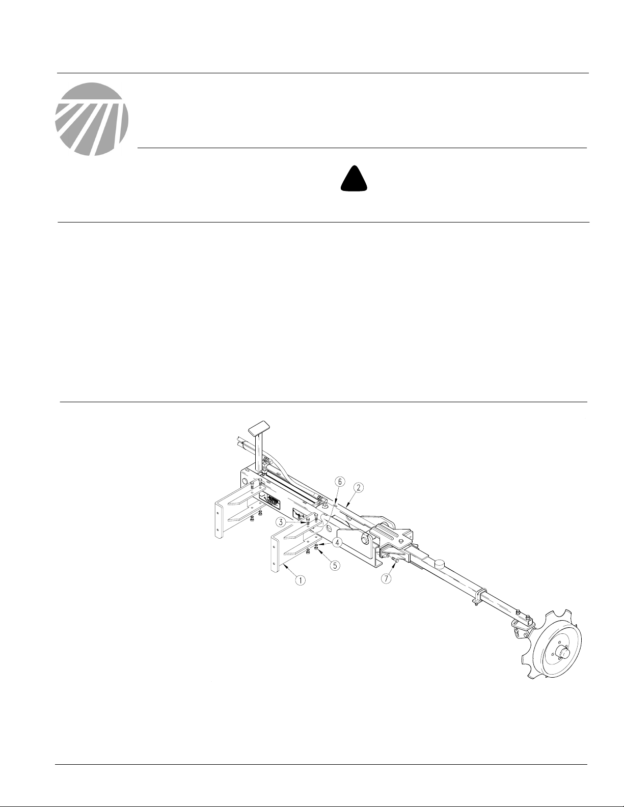
Refer to Figure 1
NOTE: The RH and LH marker assemblies are identical.
The multiple mounting slots
(6) in the assembly channel
allow for the marker to be attached to the right or left
side of the drill with the
proper mounting brackets
(1).
Use the shear bolt (7) to determine which is the lefthand marker and which is
the right-hand marker. When
markers are installed properly, shear bolt (7) will be oriented towards the front of
the hitch.
Refer to the Parts Manual for part identification.
148-152M 12’, 15’, & 20’ CPH Operator’s Manual
148-152P 12’, 15’, & 20’ CPH Parts Manual
Before You Start
Pages 5 and 6 are a detailed listing of parts included in
the Dual Marker Option. Use this list to inventory parts
received.
Tools Required
• Basic Hand Tools
24485
1. Attach two mounting
brackets (1) to each marker mount (2). NOTE: Each
marker mounts to backside of coulter toolbar.
Make sure shear bolt (7) will be positioned twoards front of
hitch once markers are attached to toolbar.
2. Secure mounting brackets (1) on marker mount (2) using 3/816 X 5 bolts (3), 3/8 lock washers (4), and 3/8-16 hex nuts (5).
© Copyright 2006 Printed
5/5/2009
Figure 1
Marker Mounting Brackets
113-479M
Page 2
Dual Marker Option
2
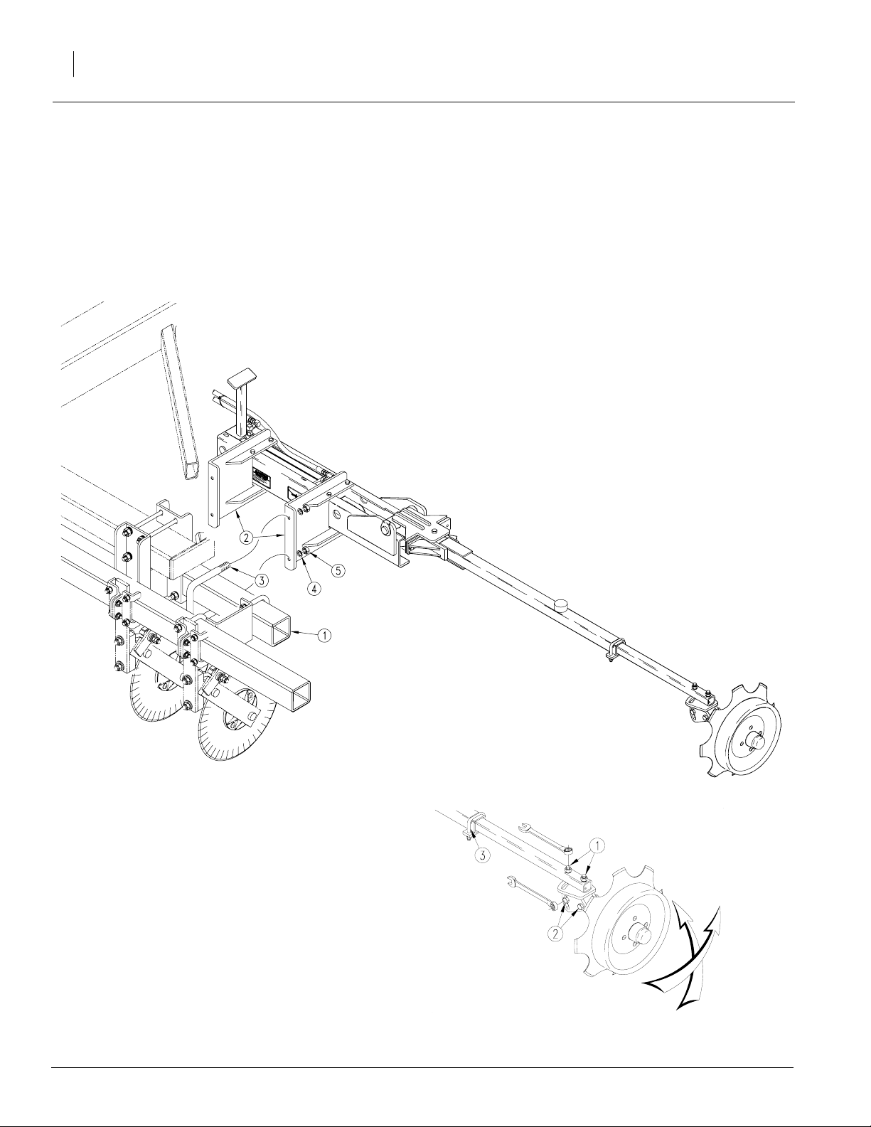
Refer to Figure 2
3. U-bolt mounting brackets (2) to rear coulter toolbar (1) as coulter spacing allows. Use 5/8-11 X 4
X 5 1/4 u-bolts (3), 5/8 lock washers (4), and 5/811 hex nuts (5) to secure mounting brackets (2) to
coulter toolbar (1).
4. Check to make sure shear bolt is oriented towards front of hitch.
5. Complete steps 3 and 4 to attach opposite marker
and mount to rear coulter toolbar.
Great Plains Mfg., Inc.
Marker Assembly
Disk Adjustment
Refer to Figure 3
The agressiveness and the mark left by the disk
may be changed by two methods:
a. Disk Angle: To change the angle of cut,
loosen the two vertical bolts (1) in the
marker arm and rotate the disk assembly.
Retighten bolts.
b. Disk Tip: To change the tip of the disk,
loosen the two horizontal bolts (5) in the
pivot adjustment. Rotate the disk assembly and retighten. The marker width adjustments are made by loosening the
marker tube u-bolt (3) and sliding it in or
out to the desired width. Retighten the ubolt.
24486
Figure 2
14061
Figure 3
Disk Adjustment
5/5/2009
Page 3
Great Plains Mfg., Inc.
Hydraulic Assembly
NOTE: JIC fittings do not require high torque. JIC
and O-Ring fittings do not require sealant. Always
use liquid pipe sealant when adding or replacing
pipe thread fittings. To avoid possible danger of
cracking hydraulic fittings from overtightening -DO
NOT use plastic sealant tape.
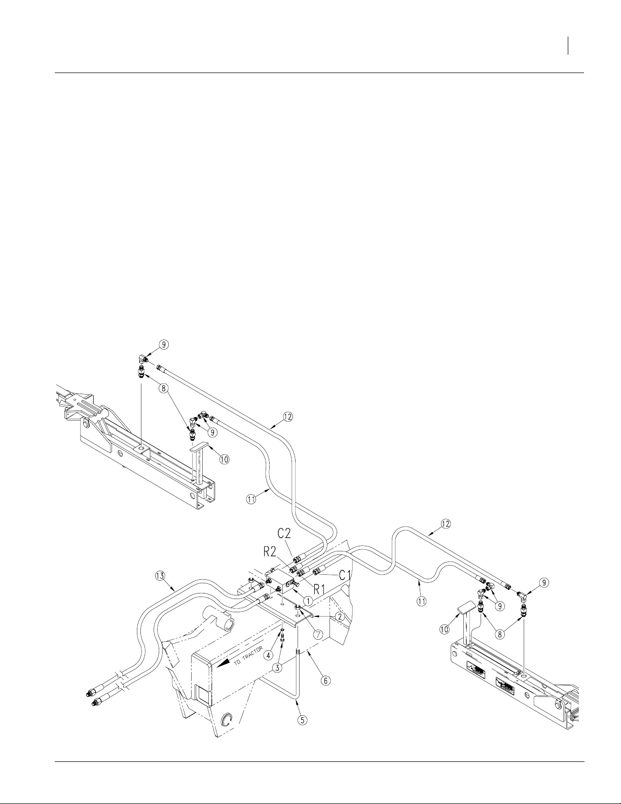
Refer to Figure 4
1. Mount sequence valve (1) on sequence valve mount
(2). Secure valve (1) on mount (2) with 3/8-16 X 1
bolts (3) and 3/8 lock washers (4).
2. U-bolt sequence valve mount (2) on hitch (6) using
1/2-13 X 8 1/16 X 9 u-bolt (5). Position sequence
valve (1) so four ports point to the rear of the implement and two ports face the tractor. Secure u-bolt
(5) with 1/2-13 nylock nuts (7).
3. If not already done, install a 9/16" male o-ring boss
x 9/16" male JIC adapter (8) into each end of both
hydraulic cylinders.
Installation Instructions
4. Install a 9/16" female JIC X 9/16" male JIC 90 degree
elbow (9) into each end of the marker cylinders.
5. Two more 9/16" female JIC x 9/16" male JIC 90 degree
elbows (9) are required on on the base end of the
marker cylinders to offset the hoses around the marker
rest post (10).
6. Route the 57" long hydraulic hoses (11) from the elbows (9) at the ports marked C1 & C2 on the sequence
valve (1) to the elbows (9) on the base ends of the
marker cylinders.
7. The 70" hoses (12) attach to the elbows (9) on the sequence valve (1) ports marked R1 & R2 and the elbows (9) on the rod end of the marker cylinders.
8. The two 156" hoses (13) attach to the remaining two
elbows (9) on the sequence valve (1) opposite the
marker ports and are routed to the hitch (6).
9. Tie all loose hoses together with cable ties provided.
3
5/5/2009
24484
Figure 4
Hydraulic Hose Assembly
Page 4

Dual Marker Option
4
Great Plains Mfg., Inc.
Bleeding the Hydraulic System
!
Escaping fluid under pressure can have sufficient force to penetrate the skin. Check all hydrualic lines and hoses before applying pressure. Fluid escaping from a very small hole can be
almost invisible. Use paper or cardboard, not body parts, to
check for suspected leaks. If injured, seek medical assistance
from a doctor that is familiar with this type of injury. Foreign
fluids in the tissue must be surgically removed within a few
hours or gangrene will result.
NOTE: JIC fittings do not require high torque. JIC
and o-ring fittings do not require sealant. Always use
liquid pipe sealant when adding or replacing pipe
thread fittings. To avoid possible danger of cracking
hydraulic fittings from overtightening - DO NOT use
plastic sealant tape.
NOTE: Check the hydraulic fluid level in the tractor
reservoir and fill to the proper level before starting
procedure. Add fluid to the system as needed. A low
reservoir level may draw air back into the system,
and can cause jerky or uneven cylinder movements.
Keep all persons clear.
NOTE: The following instructions must be followed
to bleed the markers hydraulic system. The markers
must be properly bled to displace air in the hydraulic
system and for the sequence valve to work properly.
Failure bleed the hydraulic system could cause the
marker to drop quickly to the ground causing damage to the marker and voiding the warranty.
Refer to Figure 5
1. Markers should be manually folded into transport po-
2. Connect hoses to tractor’s remote hydraulic outlets.
3. Loosen hydraulic hose fittings at rod end of marker
CAUTION!
!
DANGER!
sition when charging the hydraulic system for the first
time. Remove cylinder pin securing rod end of each
cylinder to marker link arms. Swing link arm up and
out of the way.
cylinders. With tractor at idle speed, slowly work tractor remote lever in the direction which would retract
the cylinder. DO NOT try to retract the cylinder. The
goal is to push the air from the lines leading to the
cylinder. This will only happen on one side which is
dependent on which way the sequence valve is shifted. When the air is expelled and oil starts being
pushed out, tighten hose connection at this cylinder.
cylinder base port. When the air is expelled and oil
starts being pushed out, tighten hose connection at
this cylinder.
5. Once again, slowly work tractor’s remote lever in the
direction to fully extend the cylinder and hold it there for
a few seconds. This will shift the sequence valve which
will allow you to bleed the opposite cylinder.
6. Repeat steps 3 - 5 for opposite marker cylinder.
7. Once the system is bled, operate tractor’s remote lever
several times until both cylinders stop when fully extended. Reconnect cylinders to marker link arms.
14021
Figure 5
Bleeding the Marker Cylinder
8. The marker hydraulic system is equipped with needle
valves to control how fast each marker operates. Needle valves are built into the sequence valve body.
There are two hex adjustment screws, one for raising
and one for lowering the markers. The "raise" and
"lower" needle valves are identified by stamped markings in the valve body next to the adjustment screws.
Turn adjustment screws clockwise to slow the speed
down and counter-clockwise to speed it up. Adjustments should be made for safe speeds at operating
rpm. Excessive folding speeds can cause marker
damage and may void the warranty. Be sure to tighten
the jam nuts on the hex adjustment screws to hold desired settings.
The markers cycle in the following sequence:
a. right up, left up
b. right down, left up
c. right up, left up
d. right up, left down
e. sequence repeats
4. Slowly work tractor’s remote lever in the same direction to retract the cylinder. When it is retracted, loosen hose fitting at base end of the same cylinder. With
tractor at idle speed, slowly work tractor remote lever
in the opposite direction which should put oil to the
14048
Figure 6
Sequence Valve Speed Adjustments
5/5/2009
Page 5

Great Plains Mfg., Inc.
113-219A 12’ CPH Dual Marker
Your kit includes:
Qty. Part No. Part Description
1 113-220K 12’ CPH DUAL MARKER HRDW BDL
Includes:
4 113-538H MARKER MOUNTING BRACKET WLMT
1 148-629D 1000 MARKER SEQUENCE VALVE MNT
6 800-035C CABLE TIE .31X28 8DIA 120LB
4 800-150C CABLE TIE 22.2 LONG REL
2 802-017C HHCS 3/8-16 X 1 GR5
8 802-318C HHCS 3/8-16 X 5 GR5
8 803-014C NUT HEX 3/8-16 PLT
8 803-021C NUT HEX 5/8-11 PLT
2 803-178C NUT NYLOCK JAM NUT 1/2-13
10 804-013C WASHER LOCK SPRING 3/8 PLT
8 804-022C WASHER LOCK SPRING 5/8 PLT
4 806-008C U-BOLT 5/8-11 X 4 X 5 1/4
1 806-038C U-BOLT 1/2-13 X 8 1/16 X 9 1038
1 810-197C VALVE, SEQUENCE SHOEMAKER
6 811-169C EL 9/16 MJIC 9/16 FJIC
4 811-170C AD 9/16 MORB 9/16 MJIC
1 113-434V 12’ CPH DUAL MARKER HOSE BDL
Includes:
2 811-180C HH1/4R1 057 9/16FJIC
2 811-436C HH1/4R1 156 9/16FJIC
2 811-518C HH1/4R1 070 9/16FJIC
Installation Instructions
5
2 113-541K 12’ EWNT MARKER ASSY
Includes:
1 113-534H MARKER HINGE WELDMENT
1 113-535H MARKER CYLINDER CHANNEL WLMT
1 113-536H MARKER ARM WELDMENT
1 113-537H MARKER DISC ADJUSTMENT WLMT
1 113-539H MARKER PIVOT PIN WLMT
1 113-546D MARKER LINK ARM
1 113-547S NO-TILL MARKER DISC HUB ASSY
1 113-548D MARKER DISC MOUNTING TUBE
2 800-001C GREASE ZERK STRAIGHT 1/4-28
1 802-012C HHCS 5/16-18 X 1 1/2 GR5
2 802-039C HHCS 1/2-13 X 3 GR5
3 802-041C HHCS 1/2-13 X 3 1/2 GR5
1 802-130C HHCS 1/2-13 X 2 1/2 GR5
2 802-440C RHSNB 1/2-13 X 2 3/4 GR5
1 803-011C NUT LOCK 5/16-18 PLT
4 803-020C NUT HEX 1/2-13 PLT
2 803-078C NUT LOCK 3/8-16 NYLON INSERT
1 803-147C NUT HEX NYLOCK 1/2-13
1 804-010C WASHER FLAT 5/16 USS PLT
5 804-015C WASHER LOCK SPRING 1/2 PLT
2 804-017C WASHER FLAT 1/2 USS PLT
2 804-028C WASHER FLAT 1 USS PLT
1 804-035C WASHER FLAT 1 1/4 USS PLT
2 805-058C PIN COTTER 3/16 X 2
1 805-060C PIN COTTER 7/32 X 2
1 805-187C PIN CLEVIS 1 X 2 1/4 GR5 PLT
1 806-004C U-BOLT 3/8-16 X 2 X 2 3/4
1 810-269C CYL 2 X 14X 1.12 ROD (TIE ROD)
5/5/2009
Page 6

Dual Marker Option
6
113-219A 12’ CPH Dual Marker
Your kit includes:
Qty. Part No. Part Description
1 816-170C RD BUMP STOP 2 X 1 X 1/2-13
2 818-579C DECAL WARNING PINCH
2 818-580C DECAL WARNING OVERHEAD MKR
2 890-005C BUSHING CYL 1 1/4 X 1 X 1
1 113-479M 12’ CPH DUAL MARKER MANUAL
1 502-067D HYD HOSE CLAMP LABEL
1 502-068D HYD HOSE CLAMP BRACKET
1 800-300C CABLE TIE 2 DIA MIN - ORG
1 802-009C RHSNB 5/16-18 X 1 1/4 GR5
1 803-199C NUT HEX FLANGE 5/16-18 PLT
2 838-265C DECAL REFLECTOR AMBER 1 1/2 X 9
Great Plains Mfg., Inc.
5/5/2009
Page 7

Great Plains Manufacturing, Inc.
Corporate Office: P.O. Box 5060
Salina, Kansas 67402-5060 USA
 Loading...