

Page 1

Table of Contents Index
13-Foot/4 Meter End-Wheel Drill
Operator Manual
1300 and 1300F
Manufacturing, Inc.
www.greatplainsmfg.com
Read the operator’s manual entirely. When you see this symbol, the
subsequent instructions and warnings are serious - follow without
!
exception. Your life and the lives of others depend on it!
16677
Cover illustration may show optional equipment not supplied with standard unit.
ORIGINAL INSTRUCTIONS
© Copyright 2014 Printed 2014-04-15 175-157M
Table of Contents Index
EN
Page 2

Table of Contents Index
Table of Contents Index
Page 3

Great Plains Manufacturing, Inc. Cover Index iii
Table of Contents
Important Safety Information ......................................1
Prepare for Emergencies ...............................................1
Wear Protective Equipment............................................2
Use Safety Lights and Devices ......................................3
Transport Machinery Safely ...........................................3
Shutdown and Storage...................................................4
Practice Safe Maintenance ............................................4
Tire Safety ......................................................................4
Safety At All Times .........................................................5
Safety Decals .................................................................6
Introduction ................................................................11
Description of Unit ........................................................11
Intended Usage ........................................................11
Models Covered .......................................................11
Document Family .........................................................11
Using This Manual........................................................11
Definitions................................................................. 12
Owner Assistance ........................................................12
Preparation and Setup ...............................................13
Pre-Setup Checklist......................................................13
Hitch Preparation..........................................................13
Adjusting the Drill Hitch ............................................13
Hitching ........................................................................14
Electrical Connections..................................................14
Hydraulic Hose Hookup................................................15
Operating Instructions...............................................16
General Description......................................................16
Pre-Start Checklist .......................................................16
Raising Openers for Transport .....................................17
Opener Pivot Stop ....................................................17
Lock-Out Hub ...............................................................18
Secure Markers ............................................................18
Transport ......................................................................19
Weights for Tractor Requirements............................19
Transport Checklist...................................................19
Opener Operation.........................................................20
Lowering and Raising Openers ....................................20
Loading Materials .........................................................21
Main Seed Box Loading ...........................................21
Small Seeds Box Loading ........................................21
Loading Fertilizer......................................................21
Setting Materials Rates ................................................22
Initial Seeding Depth ................................................22
Fertilizer Box Operation ............................................... 23
Applying Seed and Fertilizer .................................... 23
Divided Capacities ............................................... 23
Divider Removal................................................... 23
Seeding with Both Compartments............................ 25
Marker Operation (Option) ........................................... 26
Prepare Markers for Field Use ................................. 26
Marker Field Operations........................................... 26
Acremeter Operation.................................................... 27
Field Operations........................................................... 28
Final Field Checklist ................................................. 28
Materials Clean-Out ..................................................... 29
Main Box Clean-Out.................................................29
Fertilizer Box Clean-Out........................................... 29
Small Seeds Box Clean-Out .................................... 30
Parking......................................................................... 30
Storage ........................................................................ 30
Adjustments ............................................................... 31
Planting Depth...................................................... 31
Seed and Fertilizer Rate ...................................... 31
Opener Frame Down-Force ......................................... 32
Spring Down Pressure–All Openers ........................ 32
Marker Disk Angle Adjustment..................................... 33
Row Unit Adjustments.................................................. 34
Opener Height..........................................................35
Row Unit Down Pressure (Spring) ........................... 35
Disk Blade Adjustments ........................................... 36
Adjusting Disc Contact ......................................... 36
Disk Scraper Adjustments........................................ 36
Seed Firmer Adjustments......................................... 37
Keeton® Seed Firmer Adjustment ........................ 37
Seed-Lok® Seed Firmer Lock-Up......................... 37
Opener Depth (Press Wheel Height) ....................... 38
Troubleshooting......................................................... 39
Maintenance and Lubrication ................................... 41
General Information ..................................................... 41
Maintenance ................................................................ 42
Bleeding Hydraulics ................................................. 42
Hydraulic System Capacity ..................................42
Bleeding Lift and Marker Hydraulics .................... 43
Marker Maintenance ................................................ 44
Marker Speed Adjustment.................................... 44
Marker Shear Bolt ................................................44
Chain Maintenance .................................................. 45
Seed Flap Replacement........................................... 46
© Copyright 1998, 1999, 2002, 2005, 2006, 2008, 2014 All rights Reserved
Great Plains Manufacturing, Inc. provides this publication “as is” without warranty of any kind, either expressed or implied. While every precaution has been
taken in the preparation of this manual, Great Plains Manufacturing, Inc. assumes no responsibility for errors or omissions. Neither is any liability assumed for
damages resulting from the use of the information contained herein. Great Plains Manufacturing, Inc. reserves the right to revise and improve its products as
it sees fit. This publication describes the state of this product at the time of its publication, and may not reflect the product in the future.
2014-04-15 Cover Index 175-157M
Trademarks of Great Plains Manufacturing, Inc. include: Singulator Plus, Swath Command, Terra-Tine.
Registered Trademarks of Great Plains Manufacturing, Inc. include:
Air-Pro, Clear-Shot, Discovator, Great Plains, Land Pride, MeterCone, Nutri-Pro, Seed-Lok, Solid Stand,
Terra-Guard, Turbo-Chisel, Turbo-Chopper, Turbo Max, Turbo-Till, Ultra-Till, Ver ti-Till, Whirlfilter, Yield-Pro.
Brand and Product Names that appear and are owned by others are trademarks of their respective owners.
Printed in the United States of America
Page 4

iv 1300/F Table of Contents Index Great Plains Manufacturing, Inc.
Lubrication ................................................................... 47
Options ....................................................................... 53
Appendix A Reference Information.......................... 57
Specifications and Capacities ...................................... 57
Standard Models 1300............................................. 57
Fertilizer Models 1300F ........................................... 58
Tire Inflation Chart ....................................................... 58
Torque Values Chart.................................................... 59
Chain Routing .............................................................. 60
End Wheel to Main Jackshaft Chain ........................ 60
Main Jackshaft to Main Seed Jackshaft Chain ........ 60
Main Seed Jackshaft to Meter Drive Chain.............. 61
Fertilizer Range Chain ............................................. 61
Fertilizer Transmission Chain................................... 62
Fertilizer Meter Drive Chain ......................................62
Small Seeds Chains .................................................63
Agitator Chain ...........................................................64
Hydraulic Diagrams ......................................................65
Opener Lift (No Markers) ..........................................65
Opener Lift and Markers (Option) .............................66
Appendix B Initial Setup ............................................67
Acremeter Installation...................................................67
Scraper Installation.......................................................67
Marker Setup ................................................................68
Installing Drill Hydraulics ..............................................69
Warranty .......................................................................70
Index ............................................................................71
175-157M Table of Contents Index 2014-04-15
Page 5

Great Plains Manufacturing, Inc. Table of Contents Index Important Safety Information 1
Important Safety Information
Look for Safety Symbol
The SAFETY ALERT SYMBOL indicates there is a
potential hazard to personal safety involved and extra
safety precaution must be taken. When you see this
symbol, be alert and carefully read the message that
follows it. In addition to design and configuration of
equipment, hazard control and accident prevention are
dependent upon the awareness, concern, prudence and
proper training of personnel involved in the operation,
transport, maintenance and storage of equipment.
Be Aware of Signal Words
Signal words designate a degree or level of hazard
seriousness.
DANGER indicates an imminently hazardous situation
which, if not avoided, will result in death or serious injury.
This signal word is limited to the most extreme situations,
typically for machine components that, for functional
purposes, cannot be guarded.
WARNING indicates a potentially hazardous situation
which, if not avoided, could result in death or serious
injury, and includes hazards that are exposed when
guards are removed. It may also be used to alert against
unsafe practices.
CAUTION indicates a potentially hazardous situation
which, if not avoided, may result in minor or moderate
injury. It may also be used to alert against unsafe
practices.
Be Familiar with Safety Decals
▲ Read and understand “Safety Decals” on page 6,
thoroughly.
▲ Read all instructions noted on the decals.
▲ Keep decals clean. Replace damaged, faded and illegible
decals.
Prepare for Emergencies
▲ Be prepared if a fire starts
▲ Keep a first aid kit and fire extinguisher handy.
▲ Keep emergency numbers for doctor, ambulance, hospital
and fire department near phone.
2014-04-15 Table of Contents Index 175-157M
911
Page 6

2 1300 and 1300F Table of Contents Index Great Plains Manufacturing, Inc.
Wear Protective Equipment
▲ Wear protective clothing and equipment.
▲ Cartridge-type respirator approved for treatment dust
unless label specifies another type of respirator.
▲ Wear clothing and equipment appropriate for the job.
Avoid loose-fitting clothing.
▲ Do not wear contaminated clothing. Wash protective
clothing and equipment with soap and water after each
use. Personal clothing must be laundered separately from
household articles.
▲ Because prolonged exposure to loud noise can cause
hearing impairment or hearing loss, wear suitable
hearing protection such as earmuffs or earplugs.
▲ Because operating equipment safely requires your full
attention, avoid wearing entertainment headphones while
operating machinery.
Handle Chemicals Properly
Agricultural chemicals can be dangerous. Improper use
can seriously injure persons, animals, plants, soil and
property.
▲ Read and follow chemical manufacturer’s instructions.
▲ Wear protective clothing.
▲ Handle all chemicals with care.
▲ Avoid inhaling smoke from any type of chemical fire.
▲ Store or dispose of unused chemicals as specified by
chemical manufacturer.
Avoid High Pressure Fluids
Escaping fluid under pressure can penetrate the skin,
causing serious injury.
▲ Avoid the hazard by relieving pressure before
disconnecting hydraulic lines.
▲ Use a piece of paper or cardboard, NOT BODY PARTS, to
check for suspected leaks.
▲ Wear protective gloves and safety glasses or goggles when
working with hydraulic systems.
▲ If an accident occurs, seek immediate medical assistance
from a physician familiar with this type of injury.
175-157M Table of Contents Index 2014-04-15
Page 7
Great Plains Manufacturing, Inc. Table of Contents Index Important Safety Information 3
Use A Safety Chain
▲ Use a safety chain to help control drawn machinery
should it separate from tractor draw-bar.
▲ Use a chain with a strength rating equal to or greater than
the gross weight of towed machinery.
▲ Attach chain to tractor draw-bar support or other
specified anchor location. Allow only enough slack in
chain to permit turning.
▲ Replace chain if any links or end fittings are broken,
stretched or damaged.
▲ Do not use safety chain for towing.
Use Safety Lights and Devices
Slow moving tractors and towed implements can create a
hazard when driven on public roads. They are difficult to
see, especially at night.
▲ Use flashing warning lights and turn signals whenever
driving on public roads.
▲ Use lights and devices provided with the drill.
Keep Riders Off Machinery
Riders obstruct the operator’s view. Riders could be
struck by foreign objects or thrown from the machine.
▲ Never allow children to operate equipment.
▲ Keep all bystanders away from machine during operation.
Transport Machinery Safely
Maximum transport speed for drill is 20 mph (30 km/h).
Some rough terrains require a slower speed. Sudden
braking can cause a towed load to swerve and upset.
▲ Install transport lock and disengage the lock-out hub
before transport.
▲ Do not exceed 20 mph (30 km/h). Never travel at a speed
which does not allow adequate control of steering and
stopping. Reduce speed if towed load is not equipped with
brakes.
▲ Comply with national, regional and local laws.
▲ Follow your tractor manual recommendations for
maximum hitch loads. Insufficient weight on tractor
steering wheels will result in loss of control.
▲ Carry reflectors or flags to mark drill in case of
breakdown on the road.
▲ Keep clear of obstructions when transporting. Refer to
transport dimensions under “Specifications and
Capacities” on page 57.
2014-04-15 Table of Contents Index 175-157M
Page 8
4 1300 and 1300F Table of Contents Index Great Plains Manufacturing, Inc.
Shutdown and Storage
▲ Clean out and safely store or dispose of residual
chemicals.
▲ Secure drill using blocks and transport locks.
Lock up openers.
▲ Store in an area where children normally do not play.
Practice Safe Maintenance
▲ Understand procedure before doing work. Use proper
tools and equipment. Refer to this manual for additional
information.
▲ Work in a clean, dry area.
▲ Put tractor in park, turn off engine, and remove key before
performing maintenance.
▲ Make sure all moving parts have stopped and all system
pressure is relieved.
▲ Use caution when working on or near row units. Opener
disk edges are sharp.
▲ Disconnect battery ground cable (-) before servicing or
adjusting electrical systems or before welding on drill.
▲ Inspect all parts. Make sure parts are in good condition
and installed properly.
▲ Remove buildup of grease, oil or debris.
▲ Remove all tools and unused parts from drill before
operation.
Tire Safety
Tire changing can be dangerous and should be
performed by trained personnel using correct tools and
equipment.
▲ When inflating tires, use a clip-on chuck and extension
hose long enough for you to stand to one side–not in front
of or over tire assembly. Use a safety cage if available.
▲ When removing and installing wheels, use wheel-handling
equipment adequate for weight involved.
175-157M Table of Contents Index 2014-04-15
Page 9
Great Plains Manufacturing, Inc. Table of Contents Index Important Safety Information 5
Safety At All Times
Thoroughly read and understand the instructions in this
manual before operation. Read all instructions noted on
the safety decals.
▲ Be familiar with all drill functions.
▲ Operate machinery from the driver’s seat only.
▲ Do not leave drill unattended with tractor engine running.
▲ Do not dismount a moving tractor. Dismounting a moving
tractor could cause serious injury or death.
▲ Do not stand between the tractor and drill during
hitching.
▲ Keep hands, feet and clothing away from power-driven
parts.
▲ Wear snug fitting clothing to avoid entanglement with
moving parts.
▲ Watch out for wires, trees, etc., when folding and raising
drill. Make sure all persons are clear of working area.
▲ Do not turn tractor too tightly, causing drill to ride up on
wheels. This could cause personal injury or equipment
damage.
2014-04-15 Table of Contents Index 175-157M
Page 10
6 1300 and 1300F Table of Contents Index Great Plains Manufacturing, Inc.
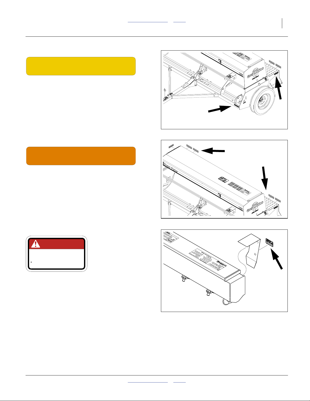
Safety Decals
Safety Reflectors and Decals
Your drill comes equipped with all lights, safety reflectors
and decals in place. They were designed to help you
safely operate your drill.
▲ Read and follow decal directions.
▲ Keep lights in operating condition.
▲ Keep all safety decals clean and legible.
▲ Replace all damaged or missing decals. Order new decals
from your Great Plains dealer. Refer to this section for
proper decal placement.
▲ When ordering new parts or components, also request
corresponding safety decals.
To install new decals:
1. Clean the area on which the decal is to be placed.
2. Peel backing from decal. Press firmly on surface,
being careful not to cause air bubbles under decal.
818-003C
Slow Moving Vehicle Reflector
Center of walkboard;
1 total
838-266C
Red Reflectors
On rear walkboard face, outside corners;
2 total
16613
20148
175-157M Table of Contents Index 2014-04-15
Page 11
Great Plains Manufacturing, Inc. Table of Contents Index Important Safety Information 7
838-265C
Amber Reflectors
On wing walkboard end faces, above steps,
front face of frame, outside corners;
4 total
20148
838-267C
Daytime Reflectors
On rear walkboard face (inboard of red reflectors);
2 total
818-518C (Option)
DANGER
MOVING CHAIN HAZARD
To prevent serious injury from moving chain:
DO NOT operate with inclosure missing
Danger: Moving Chain
On Small Seeds chain guard;
1 total
818-518C
20148
17036
2014-04-15 Table of Contents Index 175-157M
Page 12
8 1300 and 1300F Table of Contents Index Great Plains Manufacturing, Inc.
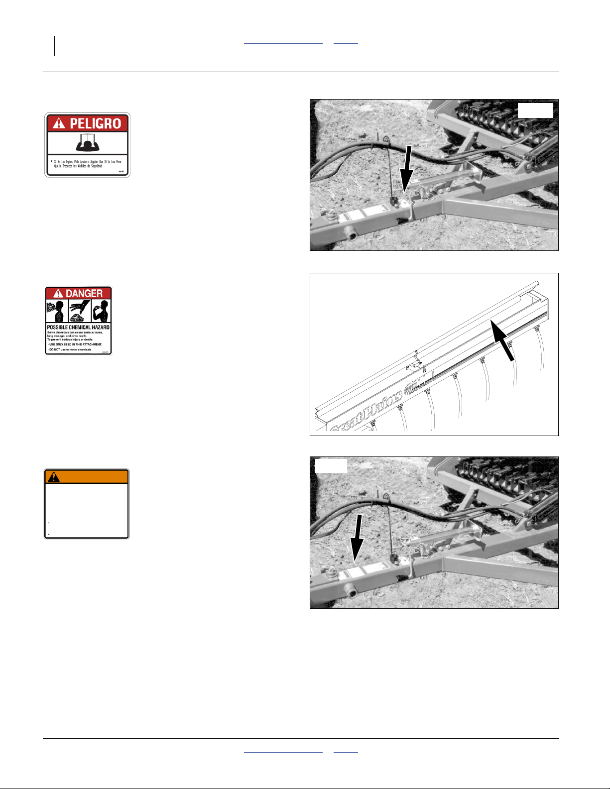
818-557C
Danger: Cannot Read English
On tongue at hitch;
1 total
838-467C (Option)
Danger: Possible Chemical Hazard
Under Small Seeds box lid;
1 total
16615
818-019C
WARNING
NEGATIVE TONGUE WEIGHT
HAZARD
Negative tongue weight can cause immediate
elevation of tongue when unhitching implement
To prevent serious injury or death:
Always be certain implement is hitched securely
to tractor drawbar before raising.
Lower implement BEFORE unhitching.
Warning: Negative Tongue Weight
On tongue at hitch;
1 total
818-019C Rev. D
13734
16615
175-157M Table of Contents Index 2014-04-15
Page 13
Great Plains Manufacturing, Inc. Table of Contents Index Important Safety Information 9
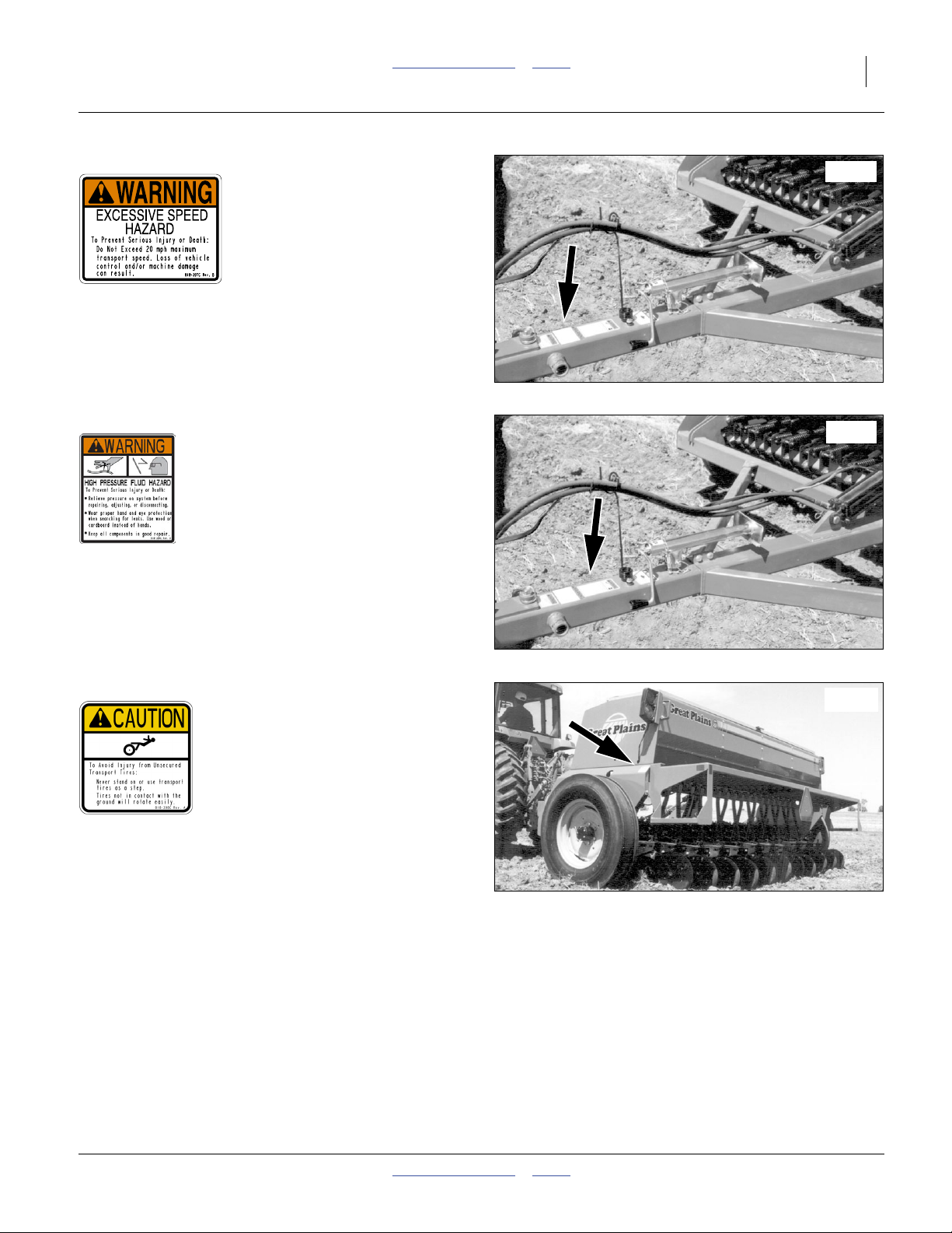
818-337C
Warning: Excessive Speed Hazard
On tongue near hitch;
1 total
818-339C
Warning: High Pressure Fluid
On tongue near hitch;
1 total
16615
16615
818-398C
Caution: Tires Not A Step
Upper rear of side frames;
2 total
16613
2014-04-15 Table of Contents Index 175-157M
Page 14
10 1300 and 1300F Table of Contents Index Great Plains Manufacturing, Inc.
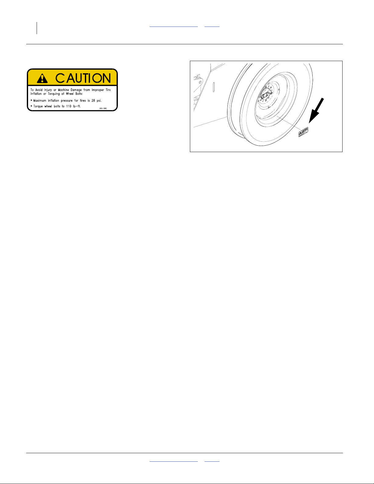
818-789C
Caution: 28 PSI Tire Pressure
On rim of each end wheel;
2 total
16616
175-157M Table of Contents Index 2014-04-15
Page 15
Great Plains Manufacturing, Inc. Table of Contents Index Introduction 11
Introduction
Great Plains welcomes you to its growing family of new
product owners. Your 13-Foot/4 Meter End-Wheel Drill
has been designed with care and built by skilled workers
using quality materials. Proper setup, maintenance, and
safe operating practices will help you get years of
satisfactory use from the machine.
Description of Unit
The 1300 and 1300F is a towed seeding implement. This
drill has a working width of 13 feet (4 m). The drill has
straight arm, double disk openers. The opener disks
make a seed bed, and seed tubes mounted between the
disks place seed in the furrow. Press wheels following
the opener disks close the furrow and gauge opener
seeding depth. A T-handle on the opener body is for
seeding depth adjustments.
The metering system is driven from the left end wheel.
Seeding rates are adjustable with the seed rate
adjustment handle and sprocket changes.
Intended Usage
Use this implement to seed production-agriculture crops
in conventional or minimum tillage applications.
Models Covered
Standard 1300 Models have 00 Series openers and a
main seed box used entirely for seed. F Models add
fertilizer meters and divide the main box for this purpose.
Either model may add optional Small Seeds capability.
1300 Models
1300-1610 16 row 10 inch (25.4 cm)
1300-2175 21 row 7.5 inch (19.1 cm)
1300-2606 26 row 6 inch 9 (15.2 cm)
1300F (Fertilizer) Models:
1300F-1610 16 row 10 inch (25.4 cm)
1300F-2175 21 row 7.5 inch (19.1 cm)
1300F-2606 26 row 6 inch 9 (15.2 cm)
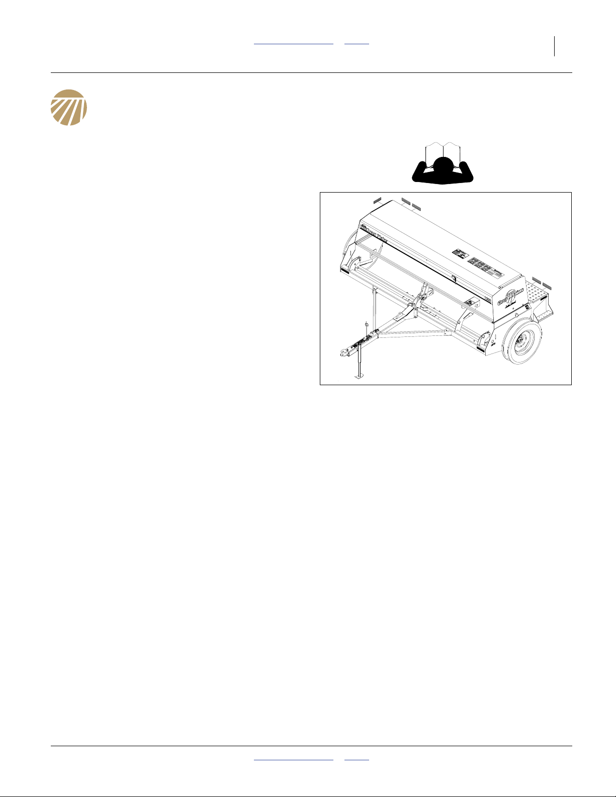
Figure 1
1300 and 1300F Drill
20148
Document Family
175-157M Owner’s Manual (this document)
175-157P 1300 and 1300F Parts Manual
175-157B Seed Rate Manual
Using This Manual
This manual familiarizes you with safety, assembly,
operation, adjustments, troubleshooting, and
maintenance. Read this manual and follow the
recommendations to help ensure safe and efficient
operation.
The information in this manual is current at printing.
Some parts may change to assure top performance.
2014-04-15 Table of Contents Index 175-157M
Page 16
12 1300 and 1300F Table of Contents Index Great Plains Manufacturing, Inc.
Definitions
The following terms are used throughout this manual.
Right-hand and left-hand as used in this manual are
determined by facing the direction the machine will travel
while in use unless otherwise stated.
Economic or Liability Risk:
Paragraphs in this format present a crucial point of information
related to the current topic.
R
Read and follow the directions to:
• remain safe,
• avoid serious damage to equipment and
• ensure desired field results.
Note: Paragraphs in this format provide useful
information related to the current topic.
Owner Assistance
If you need customer service or repair parts, contact a
Great Plains dealer. They have trained personnel, repair
parts and equipment specially designed for Great Plains
products.
Refer to Figure 3
Your machine’s parts were specially designed and
should only be replaced with Great Plains parts. Always
use the serial and model number when ordering parts
from your Great Plains dealer. The serial number plate is
located on the left side of the drill frame below the front
of the seed box.
Record your drill model and serial number here for quick
reference:
Model Number:__________________________
Serial Number: __________________________
Your Great Plains dealer wants you to be satisfied with
your new machine. If you do not understand any part of
this manual or are not satisfied with the service received,
please take the following actions.
1. Discuss the matter with your dealership service
manager. Make sure they are aware of any problems
so they can assist you.
2. If you are still unsatisfied, seek out the owner or
general manager of the dealership.
For further assistance write to:
L
Figure 2
Left/Right Notation
Figure 3
Serial Number
Product Support
Great Plains Mfg. Inc., Service Department
PO Box 5060
Salina, KS 67402
-5060
20148
16643
785-823-3276
175-157M Table of Contents Index 2014-04-15
Page 17
Great Plains Manufacturing, Inc. Table of Contents Index Preparation and Setup 13
Preparation and Setup
This section helps you prepare your tractor and drill for
use. Before using the drill in the field, you must hitch the
drill to a suitable tractor and also setup the drill.
Pre-Setup Checklist
1. Read and understand “Important Safety
Information” on page 1.
2. Check that all working parts are moving freely, bolts
are tight, and cotter pins are spread.
3. Check that all grease fittings are in place and
lubricated. See “Lubrication” on page 47.
4. Check that all safety decals and reflectors are
correctly located and legible. Replace if damaged.
See “Safety Decals” on page 6.
5. Inflate tires to pressure recommended and tighten
wheel bolts as specified. “Appendix A Reference
Information” on page 57.
Hitch Preparation
Crushing Hazard:
You may be severely injured or killed by being crushed
between the tractor and drill. Do not stand or place any part of
your body between machines being hitched. Stop tractor
engine and set park brake before installing hitch pin.
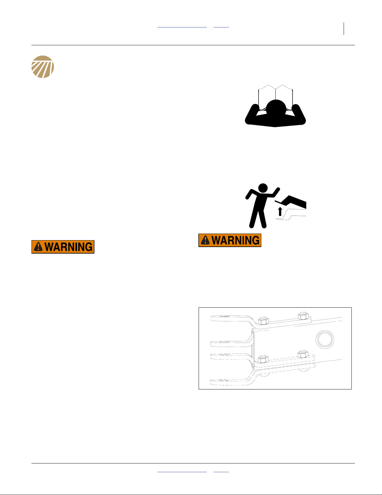
Adjusting the Drill Hitch
Adjust the drill hitch to match tractor drawbar height so
your drill frame runs level in the field.
Refer to Figure 4
1. Back your tractor up as if hitching to the drill. Park
the tractor several yards from the drill. Set the brake
and turn off the tractor.
2. Crank the drill jack until the top of the drill box is
parallel with the ground. Compare the height of the
drill hitch to your tractor drawbar.
3. If necessary, adjust the drill hitch to match your
tractor drawbar.To adjust the hitch, remove the
3
⁄4inch nuts, bolts and washers. Reposition and
re-install the clevis hitch.
Negative Tongue Weight Hazard:
This drill can have positive and negative tongue weight, which
can work the hitch pin loose during transport. To avoid serious
injury or death due to a road accident, always check that the
drill is hitched before raising the openers. Lower the openers
before unhitching.
Figure 4
Clevis Hitch Positions
16645
2014-04-15 Table of Contents Index 175-157M
Page 18
14 1300 and 1300F Table of Contents Index Great Plains Manufacturing, Inc.
Hitching
Crushing Hazard:
You may be severely injured or killed by being crushed
between the tractor and drill. Do not stand or place any part of
your body between machines being hitched. Stop tractor
engine and set park brake before installing hitch pin.
1. Slowly back the tractor toward the drill. When within
a few yards of the drill, stop and park the tractor.
2. Crank the drill jack until the drill hitch matches the
tractor drawbar height.
3. Continue backing the tractor until the drawbar and
hitch are aligned. Stop and park the tractor. Adjust
the drill tongue height until you can install the hitch
pin.
4. Install a hitch pin. Install a retaining clip to keep the
pin from working out of the hitch.
5. Secure the drill safety chain to an anchor on the
tractor capable of pulling the drill.
6. Use crank to raise jack foot. Remove pin and jack.
Store jack on top of tongue.
Negative Tongue Weight Hazard:
This drill can have positive and negative tongue weight, which
can work the hitch pin loose during transport. To avoid serious
injury or death due to a road accident, always check that the
drill is hitched before raising the openers. Lower the openers
before unhitching.
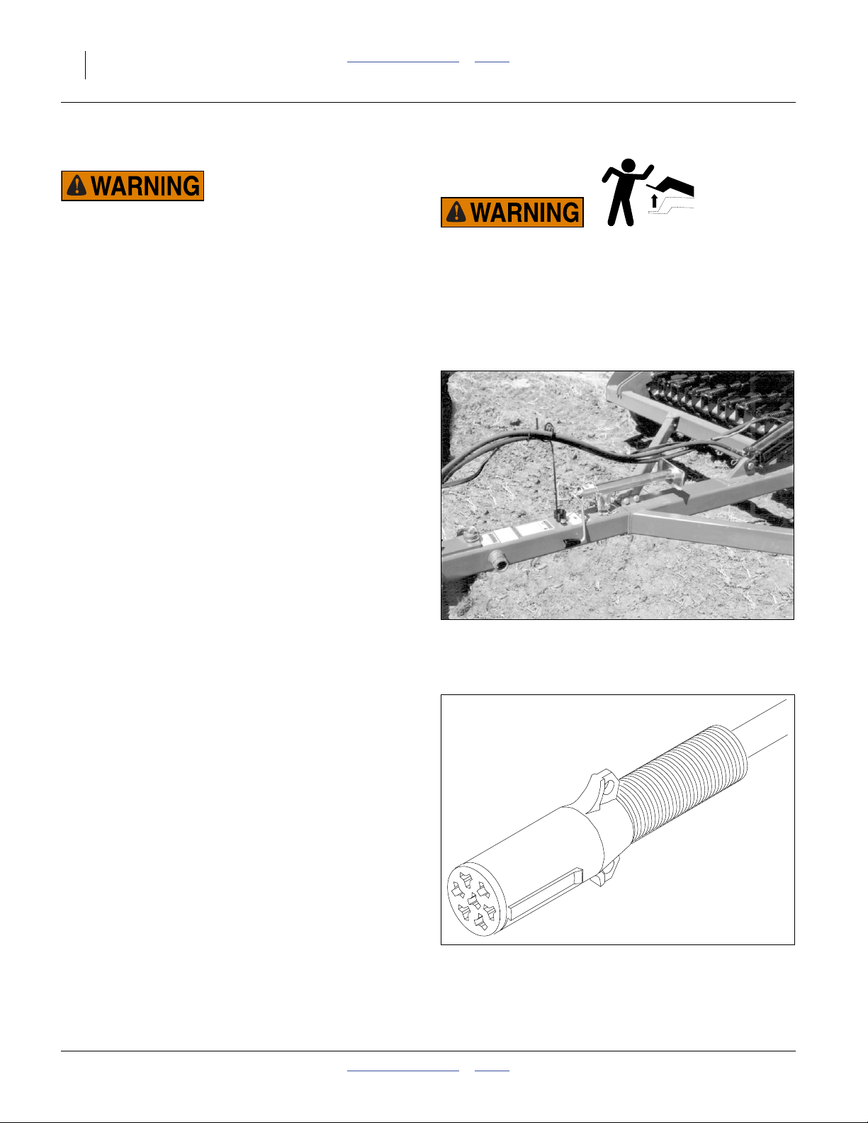
Electrical Connections
Refer to Figure 6
7. Plug drill electrical lead into tractor seven-pin
connector. If your tractor is not equipped with a
seven-pin connector, contact your dealer for
installation.
Figure 5
Jack on Storage Stob
Figure 6
Lighting Connector
16615
26467
175-157M Table of Contents Index 2014-04-15
Page 19

Great Plains Manufacturing, Inc. Table of Contents Index Preparation and Setup 15
Hydraulic Hose Hookup
High Pressure Fluid Hazard:
Only trained personnel should work on system hydraulics!
Escaping fluid under pressure can have sufficient pressure to
penetrate the skin, causing serious injury. Avoid the hazard by
relieving pressure before disconnecting hydraulic lines. Use a
piece of paper or cardboard, NOT BODY PARTS, to check for
leaks. Wear protective gloves and safety glasses or goggles
when working with hydraulic systems. If an accident occurs,
seek immediate medical attention from a physician familiar
with this type of injury.
8. Set tractor circuit for opener lift to float.
9. Plug cylinder base and rod end hoses into circuit
extend and retract ports.
2014-04-15 Table of Contents Index 175-157M
Page 20
16 1300 and 1300F Table of Contents Index Great Plains Manufacturing, Inc.
Operating Instructions
This section covers general operating procedures.
It assumes that setup items have been completed.
Experience, machine familiarity and the following
information will lead to efficient operation and good
working habits. Always operate farm machinery with
safety in mind.
General Description
Field operations are controlled by a tractor cab hydraulic
lever. When openers are lowered, a mechanical clutch
engages, and the left end wheel drives the seed meter
shaft.
Seed and fertilizer meters operate at a rate proportional
to ground speed, as set by sprockets and/or rate
handles, based on the rate charts, and calibration.
Seeding depth and furrow coverage are controlled by drill
down pressure and row unit setup.
Pre-Start Checklist
❑ Lubricate the drill as indicated under Lubrication,
“Maintenance and Lubrication” on page 41.
❑ Check the tires for proper inflation according to
“Tire Inflation Chart” on page 58.
❑ Check for worn or damaged parts and leaks.
Repair or replace before going to the field.
❑ Check all nuts, bolts and screws. Tighten bolts as
specified on “Torque Values Chart” on page 59
High Pressure Fluid Hazard:
Escaping fluid under pressure can penetrate the skin causing
serious injury. Avoid the hazard by relieving pressure before
disconnecting hydraulic lines. Use a piece of paper or
cardboard, NOT BODY PARTS, to check for suspected leaks.
Wear protective gloves and safety glasses or goggles when
working with hydraulic systems. If an accident occurs, seek
immediate medical attention from a physician familiar with
this type of injury.
175-157M Table of Contents Index 2014-04-15
Page 21
Great Plains Manufacturing, Inc. Table of Contents Index Operating Instructions 17
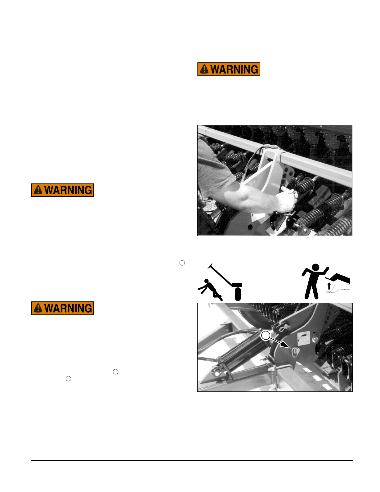
Raising Openers for Transport
Opener sub-frame is on a dedicated hydraulic circuit.
The openers raise and lower as a group, controlled from
a tractor cab lever.
The following instructions presume that the openers are
lowered, and need to be raised for transport.
Opener Pivot Stop
Refer to Figure 7
1. Hitch the drill to a suitable tractor. See “Hitching”on
page 14.
2. If markers are installed, verify that markers are
folded and secured with transport pins. See “Secure
Markers” on page 18. If not, secure them during lift
operations to secure pivot stop for transport.
Marker Pinch/Crush/Sharp Object Hazards:
Secure markers before setting pivot pin. Moving markers can
pinch at mounts crush under arms. Marker disks are sharp.
If not secured by transport pins, markers will fold and unfold
during lift and lower operations.
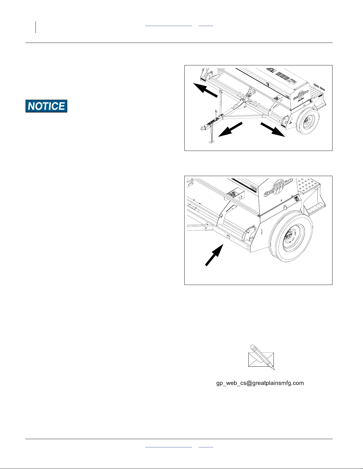
3. Retract the opener lift cylinder to fully raise the
openers. Put the tractor circuit control in Neutral to
hold cylinder position.
4. Note which lettered (A-E) down-pressure pin hole
was previously in use. This is likely to be the same
hole used when the drill next plants.
5. Remove the pin from the down-pressure adjustment
hole.
1
Loss of Control Hazard:
Failure of the hydraulic cylinder during transport causes the
openers to drop suddenly, which could lead to serious road
accidents, injury or death. To prevent an accident, always
install the pivot-stop pin in the transport-lock position before
transporting the drill.
1
2
3
Figure 7
Removing Down-Pressure Pin
16652
Negative Tongue Weight Hazard:
Raising openers on an unhitched drill causes the drill tongue
to rise suddenly, which could cause serious injury or death. Be
certain that drill is hitched securely to your tractor drawbar
and the safety chain is securely attached to tractor before
raising openers.
Refer to Figure 8
6. Insert and secure the pin in its transport lock
position .
2014-04-15 Table of Contents Index 175-157M
3
2
Openers Locked for Transport
3
Figure 8
16649
Page 22
18 1300 and 1300F Table of Contents Index Great Plains Manufacturing, Inc.
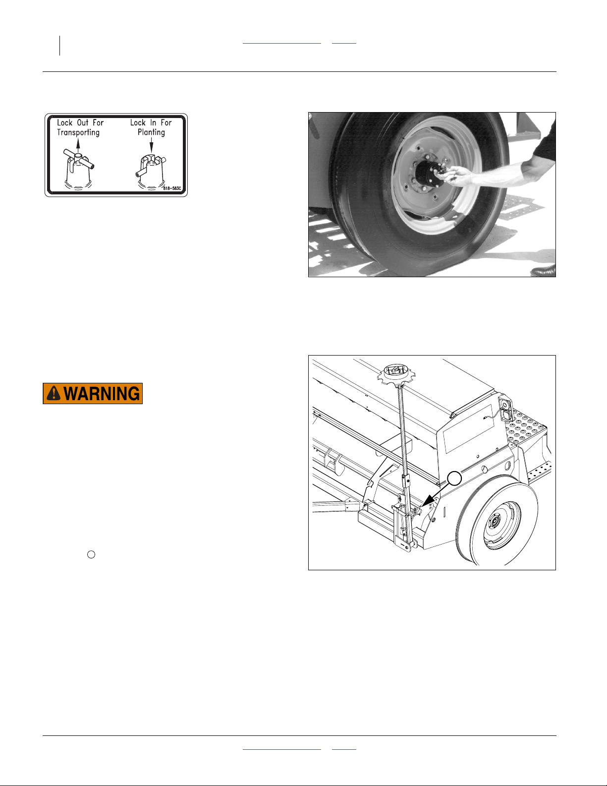
Lock-Out Hub
Refer to Figure 9
7. Disengage the lock-out hub on the left end-wheel.
Pull out on the cross-pin, lifting it out of the deeper
detents. Rotate it 90 degrees and release it into the
shallower detents.
Note: To re-engage the lock-out hub for planting, reverse
the above step. Note that the cross-pin may not
fully seat when released into the deep detents. It
self-seats during the next rotation of the wheel.
Figure 9
Wheel LockOut Hub
16654
818583C
Secure Markers
If markers are installed, they must be folded and locked
for transport.
Transport/Crush/Sharp Object Hazards:
Do not transport with markers unsecured by pins. A lowering
marker arm could cause a serious highway accident or strike
other objects and persons outside of the lane. A circuit in
Float, a disconnect at the hitch, or hydraulic hose damage
could result in a marker arm descending. Secure markers
before transport.
1. To avoid excess wear on opener discs, raise openers
and secure at raised with opener pivot stop
(page 17).
Refer to Figure 10
2. Check that marker transport pins are not in transport
1
holes (outboard holes).
3. As needed, fold a marker on each side using the lift
circuit (page 30). As each marker reaches fully
folded, set the lift circuit to Neutral.
4. Insert and secure the lock pin.
1
Figure 10
Marker Transport Pin
36274
175-157M Table of Contents Index 2014-04-15
Page 23
Great Plains Manufacturing, Inc. Table of Contents Index Operating Instructions 19
Transport
Towing the drill at high speeds or with a vehicle that is not
heavy enough could lead to loss of vehicle control. Loss of
vehicle control could lead to serious road accidents, injury
and death. To reduce the hazard:
▲ Do not exceed 20 mph (30 km/h).
▲ Do not tow a drill that, when fully loaded, weighs more
than 1.5 times the weight of the towing vehicle.
In the following table, multiply the total drill weight by
0.67 (2⁄3) to determine minimum tractor weight.
Weights for Tractor Requirements
Basic¹ Model Maximum² Configuration
Model Empty Full Empty Full
1300-1610
1300-2175
1300-2606
1300F-1610
1300F-2175
1300F-2606
1. Main seed only. No small seeds or markers.
2. Small seeds and markers.
3,500 pounds 6,200 pounds 4,000 pounds 7,000 pounds
(1570 kg) (2820 kg) (1820 kg) (3170 kg)
3,700 pounds 6,500 pounds 4,300 pounds 7,200 pounds
(1680 kg) (2930 kg) (1930 kg) (3280 kg)
4,200 pounds 6,900 pounds 4,700 pounds 7,700 pounds
(1880 kg) (3140 kg) (2140 kg) (3490 kg)
3,900 pounds 6,700 pounds 4,500 pounds 7,400 pounds
(1760 kg) (3020 kg) (2020 kg) (3370 kg)
4,100 pounds 6,900 pounds 4,700 pounds 7,700 pounds
(1880 kg) (3130 kg) (2130 kg) (3480 kg)
4,600 pounds 7,400 pounds 5,200 pounds 8,100 pounds
(2090 kg) (3350 kg) (2350 kg) (3690 kg)
Transport Checklist
Before transporting the drill, check the following items:
❑ Transport only with a tractor of proper size. See
“Specifications and Capacities” on page 57.
❑ Safety Chain in Place (page 13) Attach safety chain
to an anchor on tractor.
❑ Drill Securely Hitched (page 13)
❑ Openers Raised and Locked Up (page 17). ❑ Stopping Distance Allow sufficient stopping distance
❑ Tires (page 58) Check tires for proper inflation.
❑ Lockout Hub (page 18) Disengaged.
❑ Markers (page 18) Folded and locked.
❑ Bystanders Check that no one is in the way before
moving. Do not allow anyone to ride on the drill.
❑ Warning Lights Always use tractor and drill warning
lights in transport.
❑ Clearance (page 57) Know the maximum dimensions
of the drill in transport and follow a route that provides
adequate clearance from all obstructions.
and reduce speed prior to any turns or maneuvers. If
the drill is transported full, allow extra stopping
distance.
❑ Road Rules Comply with all national, regional and
local laws when transporting on public roads.
2014-04-15 Table of Contents Index 175-157M
Page 24
20 1300 and 1300F Table of Contents Index Great Plains Manufacturing, Inc.
Opener Operation
Opener sub-frame is on a hydraulic circuit that is shared
with markers if markers are installed. The openers raise
and lower as a group, controlled from a tractor cab lever.
If markers are installed, and unlocked, each marker side
unfolds and refolds, alternating left-to-right, with each
opener lift and lower cycle.
Lowering and Raising Openers
The following instructions presume that the openers are
raised and locked up for transport.
Refer to Figure 12
1. Determine the down-pressure pin hole , (lettered
A-E), to be used for the current conditions. If you
have no preference developed, plan to use hole “E”.
See page 32 for further information.
2. If markers are installed, verify that markers are
folded and secured with transport pins. See “Secure
Markers” on page 18. If not, secure them during lift
operations to secure pivot stop for transport.
Refer to Figure 11 and Figure 12
3. With the drill hitched to a suitable tractor, retract the
lift cylinder slightly to free the pin in its transport
lock hole position.
4. Put the tractor circuit control in neutral to hold
cylinder position.
5. Remove the pin from the transport lock position and
transfer it to the desired down-pressure adjustment
hole. Secure the pin.
6. Extend the circuit to lower the openers.
7. When the lift cylinder has reached the end of its
travel, set the tractor circuit lever to Neutral to hold it
there. Do not set the circuit to Float, or down
pressure is significantly reduced.
3
1
2
Crushing Hazard:
You will be seriously injured or killed if you are
caught between raising openers and drill frame.
Always stop tractor engine, set parking brake, and
remove key before adjusting or servicing openers.
Keep bystanders well away during drill operation.
Negative Tongue Weight Hazard:
Raising openers on unfolded, unhitched drill will
cause drill tongue to rise suddenly, which could
cause serious injury or death. Be certain that drill
is hitched securely to your tractor drawbar and
the safety chain is securely attached to tractor
before raising openers and unfolding drill.
Marker Pinch/Crush/Sharp Object Hazards:
Secure markers before setting pivot pin. Moving
markers can pinch at mounts crush under arms.
Marker disks are sharp. If not secured by transport
pins, markers will fold and unfold during lift and
lower operations.
2
Figure 11
Unlocking Openers
16636
At the start of planting, stop early in the first pass and
check drill level. The most consistent planting is achieved
when the drill frame is level with the ground, and the tops
of the opener frames are level with the ground.
If planting is unsatisfactory in tractor tire tracks, see
“Opener Height” on page 35.
Check periodically during planting. Drill weight changes
as seed and fertilizer are applied.
1
3
Figure 12
Setting Down-Pressure Pin
175-157M Table of Contents Index 2014-04-15
16652
Page 25

Great Plains Manufacturing, Inc. Table of Contents Index Operating Instructions 21
Loading Materials
Fully loaded with dense seed, the drill weighs an
additional 2700 pounds (1250 kg). Include this weight
when checking tractor capability.
The drill must be hitched for seed loading.
Load slightly more material than needed, because
consumption rates can vary between compartments
even though the furrow rates are identical.
Main Seed Box Loading
1. Check that all meter doors are positioned for the
seed size, and not set for clean-out. See Seed Rate
Manual. If loading prior to transport, set them to
position 1 (smallest seed).
2. Install or remove optional seed plugs as desired for
the row spacing planned. See “Seed Tube Plug
(Small Seeds)” on page 55.
3. If loading prior to transport, and calibration has not
yet been done, set Seed Rate Handles to 0. At 0,
and with the doors at 1, no seed can leak during
transport.
4. On 1300F (fertilizer-capable) drill models:
• Check that any offset box dividers are set to the
desired compartment ratio. See “Offset Box
Divider” on page 54.
• Check that the divider flap is set as desired
(separate compartments, or all seed). See
“Fertilizer Box Operation” on page 23.
• If seeding only from the forward (seed)
compartment, flip the top spill flap back to prevent
seed from entering the fertilizer compartment. See
“Fertilizer Box Operation” on page 23.
5. Take all necessary materials safety precautions if the
seed is treated.
6. Load seed evenly into seed boxes.
7. To reduce wear, remove main shaft drive chains for
small seed boxes.
Small Seeds Box Loading
1. If loading prior to transport, and calibration has not
yet been done, set Seed Rate Handles to 0. At 0, no
seed can leak during transport.
2. Take all necessary materials safety precautions if the
seed is treated.
3. Load seed evenly into seed boxes.
4. To reduce wear, remove main shaft drive chains for
main seed boxes.
Loading Fertilizer
Load fertilizer after transport if possible. Some spillage
can occur through meters during transport, even with the
drive system disengaged.
1. Check that fertilizer clean-out door is closed and all
latches are secure.
2. Check that any offset box dividers are set to the
desired compartment ratio. See “Offset Box
Divider” on page 54.
3. Check that the divider flap is set as desired. See
“Fertilizer Box Operation” on page 23.
4. Flip the top spill flap forward to prevent fertilizer from
entering the seed compartment. See “Fertilizer Box
Operation” on page 23.
Possible Chemical Hazards:
Take all necessary materials safety
precautions.
5. Load fertilizer evenly into fertilizer compartment.
6. To reduce wear, remove drive chain for seed box not
used.
2014-04-15 Table of Contents Index 175-157M
Page 26

22 1300 and 1300F Table of Contents Index Great Plains Manufacturing, Inc.
Setting Materials Rates
Seeding and application rates are independent for all
boxes (changing rates on one does not affect the others).
Rate setting steps, and rate calibration, are different for
each box. See Seed Rate Manual (175-157B).
All of the boxes use fluted-feed meters. Actual rates
frequently vary from chart rates due to variations in
materials, conditions and application speed. Calibration
is strongly encouraged. It is also wise to monitor material
consumption in the field, both to confirm the calibration,
and to catch any stoppages or other malfunctions.
Calibration is described in the rate setting topics of the
Adjustments section.
Note: No meters operate if the lock-out hub is
disengaged. Be sure to re-engage the hub after
transport and calibration.
Initial Seeding Depth
Refer to Figure 13
1. Set opener seeding depth by adjusting press-wheel
height . To adjust, first raise openers slightly, then
lift and slide T handles on top of openers. Adjust
all press wheels to the same height. T handles
adjust at1⁄4inch (6.4 mm) seeding depth change per
minimum handle step.
• For more shallow seeding, slide T handles
• For deeper seeding, slide T handles backward
1
2
forward toward implement.
away from implement.
F
F
2
B
B
2. While seeding, remember:
• Keep the top of the opener frames level with the
ground for consistent seeding depth.
• Raise openers before turning. Never back up or
turn sharply with openers in the ground. Doing so
will plug openers and may damage equipment.
• Check periodically for plugged openers and
hoses.
For information on opener adjustments, “Row Unit
Adjustments” on page 34. For information on
troubleshooting opener problems, see
“Troubleshooting” on page 39.
175-157M Table of Contents Index 2014-04-15
Figure 13
Initial Opener Depth
1
26441
Page 27

Great Plains Manufacturing, Inc. Table of Contents Index Operating Instructions 23
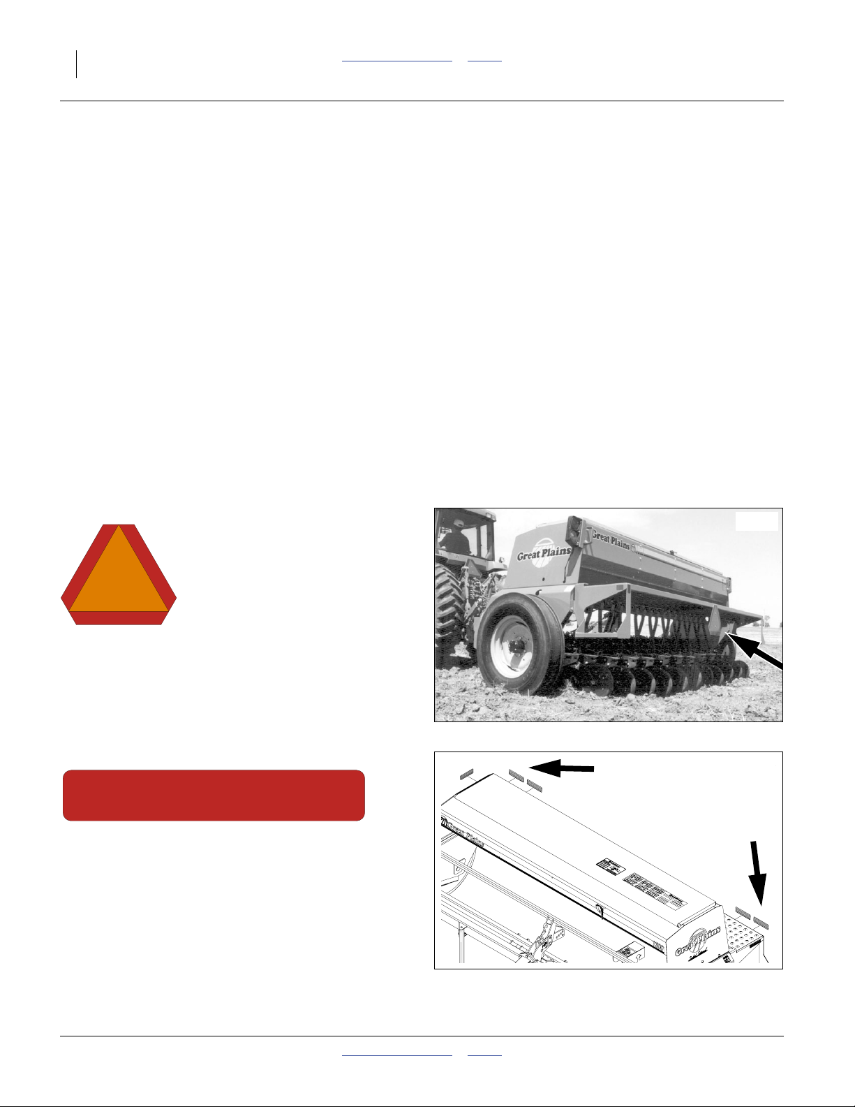
Fertilizer Box Operation
The 1300F models are equipped with a main box
compartment capable of planting seed only, or seeding
and applying fertilizer in the same field pass. Use only
dry, granular fertilizer in the fertilizer box.
60%
Seed
40%
Fert.
60%
Seed
40%
Seed
Applying Seed and Fertilizer
1. Clean any seed or debris from fertilizer
compartment. See “Fertilizer Box Clean-Out” on
page 29.
Refer to Figure 14
2. Adjust dividers between seed and fertilizer
compartments to desired capacity.
The standard dividers partition the drill box into:
60% seed : 40% fertilizer, or; 100% seed (page 25).
The optional offset dividers partition the drill box into:
68% seed : 32% fertilizer, 55% seed : 45% fertilizer,
or; 100% seed (see page 25).
Divided Capacities
Capacity Ratio Total Capacity
Divider Seed Fertilizer Seed Fertilizer
None
Standard
Offset
to rear
Offset
to front
Divider Removal
Refer to Figure 15 (which depicts a smaller 9 foot box for
clarity - the 13 foot box has four partitions)
a. Remove the5⁄16inch bolts and flange nuts from
tabs at each end of drill box (2 locations).
b. Remove the5⁄16inch bolts and nuts from lid
hinge brackets (3 locations).
c. Loosen but do not remove the1⁄4inch bolts and
nuts that clamp the lid assembly angle irons to the
plastic dividers .
d. Lift lid assembly out of drill box. Lift dividers out
of drill box. Reinstall standard or offset dividers.
e. Reinstall lid assembly by reversing step d through
step a.
100% 0%
60% 40%
68% 32%
55% 45%
3
6
9
8 9
43.2 bu
(1523 l.)
25.9 bu
(914 l.)
29.4 bu
(1036 l.)
23.8 bu
(838 l.)
1 2
4 5
8
17.3 bu
(609 l.)
13.8 bu
(487 l.)
19.4 bu
(685 l.)
7
0
Standard Divider
Configurations
68%
Seed
32%
Fert.
Offset Divider
Configurations
Figure 14
Seed Box Divider
55%
Seed
45%
Fert.
27003
1
8
7
9
2
3
2
3
1
6
5
4
Figure 15
Box Divider Removal
27050
2014-04-15 Table of Contents Index 175-157M
Page 28

24 1300 and 1300F Table of Contents Index Great Plains Manufacturing, Inc.
Refer to Figure 16
6. Check that the seed/fertilizer flap is closed so seed
and fertilizer cannot pass between compartments.
Flap flips forward to block passage. The flap top
edge is secured to the dividers. Rotate the bent clips
to engage the edge of the flap, and tighten the
knobs.
Refer to Figure 17
7. Check that fertilizer clean-out door is latched
securely as shown. Close all door latches before
1
loading fertilizer compartment.
Refer to Figure 18
8. Open main seed box lid.
9. Raise spill flap over fertilizer compartment and swing
it forward until it rests against open drill box lid. The
spill flap serves as a spill guard to keep fertilizer out
of the seed compartment.
10. Fill fertilizer compartment.
11. Calibrate fertilizer application rate as explained in the
Seed Rate manual.
Figure 16
Seed/Fertilizer Flap Closed
1
Figure 17
Clean-out Door Latch
16383
16377
Figure 18
14875
Spill Flap Open to Fertilizer
175-157M Table of Contents Index 2014-04-15
Page 29

Great Plains Manufacturing, Inc. Table of Contents Index Operating Instructions 25
Seeding with Both Compartments
1. Clean out boxes. See “Main Box Clean-Out” on
page 29 and “Fertilizer Box Clean-Out” on
page 29.
Refer to Figure 19
2. Open divider door between seed and fertilizer
compartments. To open door, loosen knobs .
Loosen knobs until bent clips can be turned away
from door .
3. When all bent clips have been turned, lift vinyl dew
shield (not shown) and flip the flap backward over
fertilizer tray openings .
1
2
3
1
1
2
1
1
3
Refer to Figure 20
4. With seed/fertilizer flap covering fertilizer
openings, lower vinyl dew shield to hold flap over
fertilizer openings and away from divider.
Refer to Figure 21
5. To avoid unnecessary wear, remove the chain from
the clutch shaft to the fertilizer drive.
2
4
Figure 19
Open Seed/Fertilizer Flap
4
Figure 20
Flap Secured
16383
2
16380
Figure 21
Fertilizer Drive Chain
2014-04-15 Table of Contents Index 175-157M
17047
Page 30

26 1300 and 1300F Table of Contents Index Great Plains Manufacturing, Inc.
Marker Operation (Option)
Prepare Markers for Field Use
If markers are not to be used for field operations, leave
the pins in their transport lock positions. There is no
harm in operating the lift circuit with markers locked up.
1. Set the lift circuit remote to Float to relieve pressure.
Set the circuit to Neutral to prevent movement. Shut
off the tractor.
Refer to Figure 22
2. At each marker, remove the transport pin from the
(outboard) locking holes.
3. Move the pin to the (inboard) storage holes , and
secure with hairpin cotter.
If marker fold and unfold speeds are known to be
satisfactory, the markers are now ready for field use.
To adjust marker speed, see page 44.
1
2
Marker Field Operations
Markers share a common remote circuit with the lift
cylinder. Marker cylinders are controlled by an automatic
sequence valve that restricts oil flow to one marker at a
time.
• Whenever a lift operation is performed, an extended
marker folds.
• Whenever a lower operation is performed, a folded
marker extends.
You may need to allow extra time for both opener and
marker operations to complete, compared to just raising
and lowering openers.
Operating One Side Only
Leave the unused side in transport lock.
Operate the lift circuit twice for each raise and lower
cycle.
Two Sides Out
it is possible to both deliberately and unintentionally
deploy markers on both sides.
At the start of lower/unfold, briefly reverse the level for
the lift circuit, then resume lower (before the lowering
marker is fully raised). This causes the other side to
enter unfold as well.
If two markers are out unintentionally, perform a fold.
Upon the next unfold, only one side deploys.
Folding with Both Sides Out
Perform two complete lower/raise operations. The
markers fold one side at a time. Install lock pins as
appropriate for the next movement.
Transport/Crush/Sharp Object Hazards:
Verify that the lift circuit is in Float or Neutral before
removing transport pins. Keep all persons well clear of
markers during lift/lower marker fold/unfold operations.
Un-pinned markers fold and unfold when the lift circuit is
extended or retracted. Markers have multiple pinch points.
Lowering arms can crush. Marker disks are sharp.
1
2
Figure 22
Marker Transport Pin Release
36274
175-157M Table of Contents Index 2014-04-15
Page 31

Great Plains Manufacturing, Inc. Table of Contents Index Operating Instructions 27
Acremeter Operation
The acremetera counts shaft rotations whenever the
shaft is rotating - normally this is only with the drill
lowered and in motion. The meter is programmed to
display rotations as acres or hectares, when using all
rows, factory-specified tires and tire inflations.
Note: Unusual conditions and/or non-standard row
spacings can cause the acremeter tally to vary
somewhat from actual acres planted.
Refer to Figure 23
Acremeters supplied with model 1300/F drills have
varied over time. For operational details (modes, resets,
calibration), see the manual supplied with the acremeter:
Meter Style and Manual
194-074M 152-314M
1 3
152-325M 194-209M
2 4
1
2
3
4
Figure 23
Acremeters
34776
34937
27378
36275
a. An electronic acremeter is available as an upgrade for older drills having a mechanical acremeter.
2014-04-15 Table of Contents Index 175-157M
Page 32

28 1300 and 1300F Table of Contents Index Great Plains Manufacturing, Inc.
Field Operations
Final Field Checklist
❑ Drill hitched and chained. See page 14.
❑ Seed and fertilizer rates set per charts and
calibration. See Seed Rate Manual.
❑ Lockout hub engaged. See page 18.
❑ Record acremeter reading if acreage monitoring is
desired.
❑ Down-pressure adjustment pin configured. See
page 20.
❑ One or both markers released from transport lock
(if installed and to be used). See page 26.
❑ Materials loaded. See page 21.
1. Pull the raised drill into starting position at the first
pass.
2. Lower the drill (page 20).
3. If markers are installed and to be used, verify that
the desired marker side is deployed, otherwise raise
and lower a second time.
4. Pull forward at the intended planting speed.
Optimum planting speed depends on conditions, and
is typically between 5 to 8 mph (8 to 13 km/h).
If openers are bouncing, or not operating at a
consistent penetration depth, reduce speed.
5. Stop shortly into the first pass and check drill level.
Both drill frame and opener frames need to be
parallel to the ground for most consistent results.
Also check the seed furrow in between the openers
and press wheels, and make sure that seed is being
delivered, and being covered.
6. At the end of each pass, retract the tractor circuit for
opener lift. Seeding stops automatically when the
openers are raised.
7. Check material consumption to ensure that it is
being used at expected rates, and that you don’t run
out.
8. Check opener level and planting depth, which can
change as the drill empties and becomes lighter.
9. At the conclusion of planting, raise the openers and
lock them up by moving the down-force adjustment
pin back to the transport lock hole (page 17).
10. If substantial quantities of materials remain, consider
performing a clean-out prior to transport (page 29),
to make a safer load, and reduce wear on the tires.
Note: If re-using calibrated rates from a prior planting,
make sure that meter scales are correctly set, and
not still at zero for transport. make sure chains are
in place for boxes to be used.
Field Results Risk:
For consistent opener down pressure, fully extend the cylinder
every time you lower the openers.
Equipment Damage Risk:
Do not make sharp turns with openers in the ground.
Equipment Damage Risk:
Never back up with openers in the ground. Seed tube plugging
and equipment damage is likely.
Note: Some row spacings have unequal numbers of row
units served by each box compartment. The
compartments with more rows run out of material
first.
175-157M Table of Contents Index 2014-04-15
Page 33

Great Plains Manufacturing, Inc. Table of Contents Index Operating Instructions 29
Materials Clean-Out
Main Box Clean-Out
Refer to Figure 24, which depicts the seed cup door handle
in a normal operating position.
1. Set the Seed Rate Handle to zero (0) for the section
of the drill to be cleaned out. This moves the seed
cup sprockets out of the seed path.
2. Position a tarp or bucket under each row or set of
rows to be cleaned out.
3. At the seed cup for that row, pull the door handle
out of the operating detent range, and swing it down
to position .
4. Open the main seed box and use a small brush to
sweep seed toward seed cups set to clean-out. If
seed does not flow freely, inspect seed cup, hose
and seed tubes for obstructions.
5. Wash out the seed box with high pressure water.
It is not necessary to operate the seed meter drive shaft
for clean-out. With the Seed Rate set to zero, nothing
moves inside the seed cups; however, an inspection of
the flutes for excess wear and damage does require
shaft rotation.
Set the Seed Rate Handles to 100 and disengage the
lock-out hub. With openers lowered to engage the clutch,
the seed meter jackshaft can be slowly turned with the
calibration crank, while another person inspects the
flutes from the open seed boxes.
2
Fertilizer Box Clean-Out
After applying fertilizer, clean drill boxes as soon as
possible. Fertilizers often contain chemicals corrosive to
metal.
Refer to Figure 25
With a small scoop or can, remove as much fertilizer as
possible from drill boxes.
Clean-out releases material across the entire length of a
section box. Have collection equipment prepared.
Release all clean-out latches on a drill section, and open
clean-out door. Leave door open until after washout.
Refer to Figure 26
Wash inside of drill boxes with water under high
pressure. To aid clean out, lift vinyl dew shield and spray
into fertilizer trays (with clean-out door open).
Let drill boxes dry before closing clean-out doors.
1
1
1
2
Figure 24
Seed Cup Clean-out
Figure 25
A Fertilizer Clean-out Latch
26211
16376
Figure 26
Dew Shield at Openings
2014-04-15 Table of Contents Index 175-157M
16382
Page 34

30 1300 and 1300F Table of Contents Index Great Plains Manufacturing, Inc.
Small Seeds Box Clean-Out
1. Open lid of each box and scoop out as much seed as
possible.
2. To recover remaining seed, place a collection tarp
under the small seeds tubes at the openers.
3. Raise drill.
4. Set seed rate handles to 100.
5. Rotate calibration crank or end wheel until no seed
flows.
6. If a vacuum cleaner is available, remove any residual
seed from top of meters.
Parking
Following these steps when parking for less than 36
hours. For longer periods, see Storage, the next topic.
1. Fold and lock both markers (page 26, if markers
installed and used).
2. Position drill on a level, solid area.
3. Remove jack from storage location on top of tongue
and pin it on post on the top of the tongue as shown
on page 14. Extend jack until weight of tongue is on
jack. Leave tractor hitched for the moment.
4. Lower openers and reduce hydraulic circuit pressure
to zero (Float circuit).
5. Unplug drill hydraulic hoses and electrical lines from
tractor.
6. Remove hitch pin first, then safety chain from tractor
drawbar.
Negative Tongue Weight Hazard:
This drill has a negative tongue weight when openers are
raised. Lower openers and remove hydraulic pressure before
unhitching the drill in the unfolded position. Unhitching with
the openers raised will result in sudden elevation of the
tongue, causing injury or death.
Use caution when removing the hitch pin. Slight tongue
elevation may occur, even with openers and jack lowered.
Storage
Store the drill where children do not play. If possible,
store it inside for longer life.
1. Plug or cap seed delivery and fertilizer tubes to
prevent pest entry.
2. Un-pin the rod end of the lift cylinder. Fully retract the
cylinder to prevent rust.
3. Perform the drill Parking checklist.
4. Lubricate the drill at all points listed under
“Lubrication” on page 47.
5. Check all bolts, pins, fittings and hoses. Tighten,
repair or replace parts as needed.
6. Check all moving parts for wear or damage. Make
notes of any parts needing repair before the next
season.
7. Use touch-up paint to cover scratches, chips and
worn areas to prevent rust.
175-157M Table of Contents Index 2014-04-15
Page 35

Great Plains Manufacturing, Inc. Table of Contents Index Adjustments 31
Adjustments
To get full performance from your drill, you need an
understanding of all component operations, and many
provide adjustments for optimal field results. Even if
planting conditions rarely change, some adjustment
items need periodic attention due to normal wear.
The 1300 and 1300F have double-disk openers with
depth-controlling press wheels mounted on floating
opener frames. Opener bodies are staggered for easy
soil flow. All openers pivot on a common axis to maintain
consistent depth as the opener frames follow contours. A
spring provides the down pressure necessary for opener
double disks to open a seed furrow. The spring allows
openers to float down into depressions and up over
obstructions. Individual openers can be adjusted to
account for tire tracks.
Planting Depth
Setting nominal planting depth, and achieving it
consistently, is affected by multiple adjustable drill
functions, from greatest to least effect they are:
• Opener Depth (Press Wheel Height)
• Opener Frame Down-Force,
• Row Unit Down Pressure (Spring),
• Opener Height, and;
• Disk Blade Adjustments (as blades wear).
Seed and Fertilizer Rate
Details are found in the Seed Rate Manual (175-157B).
Materials are applied by fluted feed meters driven by the
left end wheel. Independent mechanisms main seed,
fertilizer and optional small seeds application.
Adjustment Page The Adjustment Affects
Main Box Seed Rate Refer to Seed Rate Manual (175-157B)
Fertilizer Rate Refer to Seed Rate Manual (175-157B)
Small Seeds Rate Refer to Seed Rate Manual (175-157B)
Hitch Preparation 13 Frame Level
Opener Frame Down-Force 32 Consistent seeding depth
Marker Adjustments
Marker Disk Angle 33 Visibility of marker groove in field
Marker Speed 44 Time required for raise/lower cycle
Marker Extension 68 Correct offset for passes
Row Unit Adjustments 34
Opener Height 35 Seeding depth in tire tracks
Row Unit Down Pressure (Spring) 35 Level row units and consistent seeding depth in tire tracks
Disk Blade Adjustments 36 Consistent seeding depth
Disk Scraper Adjustments 36 Consistent seeding depth
Seed Firmer Adjustments 37 Consistent seed placement and coverage
Opener Depth (Press Wheel Height) 38 Seeding depth.
2014-04-15 Table of Contents Index 175-157M
Page 36

32 1300 and 1300F Table of Contents Index Great Plains Manufacturing, Inc.
Opener Frame Down-Force
To properly adjust seeding depth, you need an
understanding of how the opener frame, opener springs,
disks and press wheels work. The opener frame
adjustment affects all rows at once.
Refer to Figure 27 and Figure 28
The openers are mounted on a pivoting tube .
A hydraulic cylinder mounted on a floating lug controls
the openers. Springs on the opener bodies provide down
pressure for the opener disks to cut a seed furrow. An
adjustable pivot-stop pin limits the rotation of the
floating lug and thereby controls spring length and down
pressure on all openers.
Changing the position of the pivot-stop pin changes
opener down-pressure across the drill. You can also
change the spring length or mounting height of individual
openers, such as in tire tracks.
Press wheels are mounted on the opener bodies behind
the opener disks, and perform two functions:
• They close the furrow and firm the seed bed. To
provide consistent seed firming, the press wheels are
free to move down from their normal operating
position. This maintains pressing action even if the
opener arm lifts at obstructions.
• The press wheels control opener depth. The higher
the press wheels run, the deeper seed is placed.
2
1
3
1
Pivot
4
Figure 27
Down-Pressure Decal
Point
818827C
Spring Down Pressure–All Openers
The amount of down pressure needed for the opener
disks to penetrate the soil varies with field conditions.
The objective in selecting a pivot-stop pin hole, and a
press wheel height, is to achieve the desired planting
depth while keeping the drill frame and the row unit
frames level with the ground.
Note: The setting of the pivot-stop pin interacts with
the setting of the press wheel height. When
adjusting one, recheck the other.
To increase or decrease all-rows spring down pressure:
1. Raise the drill (to free the pin).
2. Move the pivot-stop pin .
The holes in the floating lug are lettered:
A provides the greatest down pressure and
E provides the least.
As the pin is moved to hole for transport, keep records
of what hole is optimal for fields and conditions worked.
Note: To maintain consistent opener down pressure, fully
extend the hydraulic cylinder each time you lower
the openers.
3
2
4
2
Figure 28
Adjusting Down-Pressure Pin
2
16652
175-157M Table of Contents Index 2014-04-15
Page 37

Great Plains Manufacturing, Inc. Table of Contents Index Adjustments 33
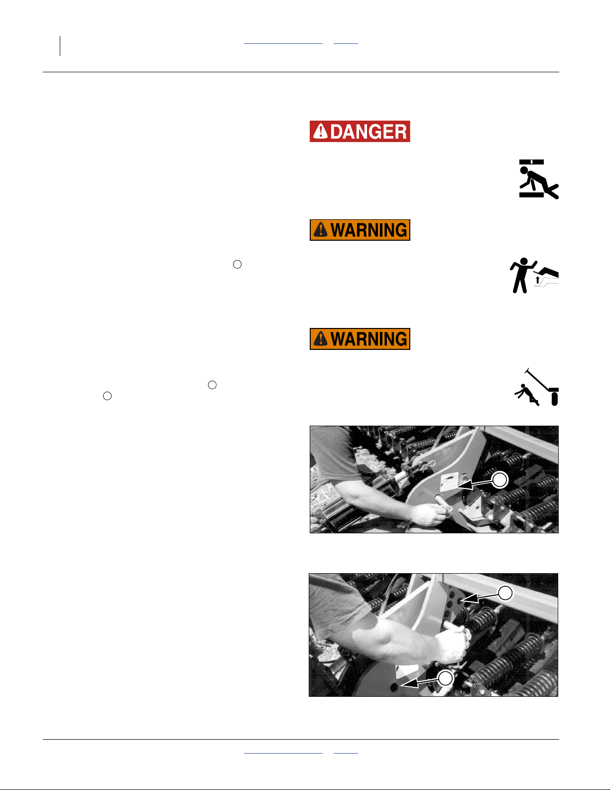
Marker Disk Angle Adjustment
Sharp Object Hazard:
Use caution when making adjustments in this area. Marker
disks may be sharp.
Refer to Figure 29
To change angle of cut, and the width of the mark, loosen
1
⁄2-inch bolts holding disk assembly.
1
For a wider mark (W), increase the angle of the marker
with respect to the tube . For a narrower mark (N),
2
reduce the angle.
You can also invert the disk blade on the hub to change
the direction of throw.
Tighten bolts .
1
Note: The direction of travel (T) tends to drive the disk
angle to Wide. If bolts are not tight enough, or
loosen over time, the disk will slip into the Wide
mark configuration.
W
N
1
Figure 29
Marker Disk Angle
2
T
11757
2014-04-15 Table of Contents Index 175-157M
Page 38

34 1300 and 1300F Table of Contents Index Great Plains Manufacturing, Inc.
Row Unit Adjustments
Refer to Figure 30 (which depicts a row unit fully populated
with all optional accessories [except scraper and Keeton®]
supported for use with the 1300 and 1300F drills)
From front to back, a Great Plains 00 Series row unit can
include the following capabilities (some optional):
1. Opener height adjustment: standard
If a few rows need to run deeper, such as in tire
tracks, the arm’s pivot point may be lowered. See
“Opener Height” on page 35.
2. Single Down Pressure Spring: standard
Each row unit is mounted on the drill as a pivoting
arm which allows the row unit to independently move
up and down. The adjustable spring provides the
force to get the row unit and attachments into the
soil. See “Row Unit Down Pressure (Spring)” on
page 35.
3. Disc Blades: standard, 2 per row unit
Double disc blades open a furrow, creating the seed
bed. Spacers adjust the blades for a clean furrow.
See “Disk Blade Adjustments” on page 36.
4. Seed delivery tube: standard
No adjustments are necessary.
5. Disk Scraper: standard (not shown)
In sticky soils, a scraper helps keep the opener disks
operating freely. A slotted scraper is standard. A
spring-loaded carbide scraper is optional. See
“Carbide Disk Scraper” on page 55.
6. Seed firmer:
seed flap (not shown) standard:
1
2
4
5
3
Figure 30
00 Series Row Unit
6
7
7
26382
Seed-Lok® firming wheel (shown)
Improves seed-soil contact. See “Seed-Lok® Seed
Firmer Lock-Up” on page 37.
Keeton® seed firmer (not shown)
Improves seed-soil contact, and provides a stable
arm for a low-rate liquid fertilizer delivery tube. See
See “Keeton® Seed Firmer Adjustment” on
page 37.
7. Press wheels: standard (choice of types)
These close the seed trench. The wheels also
support the free end of the row unit, and provide the
primary control over seeding depth. See “Opener
Depth (Press Wheel Height)” on page 38.
175-157M Table of Contents Index 2014-04-15
Equipment Damage Risk:
Do not back up with row units in the ground. To do so will
cause severe damage and row unit plugging.
Page 39

Great Plains Manufacturing, Inc. Table of Contents Index Adjustments 35
Opener Height
The depth to which the opener disk blades penetrate the
soil is controlled in front by the tool bar and pivot (opener
height), and in the back by the press wheel height.
If the actual ground level is lower for some rows, such as
those in tire tracks, you can lower that row unit by
lowering the pivot point.
Refer to Figure 31
1. Raise the drill just enough to relieve tension in the
down-pressure spring.
2. Remove the bolt from the upper hole .
3. Re-position the arm at the lower hole , and secure
with bolt.
Note: No spring tension or position adjustment is
required. The pivot holes are designed for neutral
effect on spring tension (the bolt at the top end of
the spring uses a hole that depends on spring
length, and not opener height.)
1
2
3
1
2
Figure 31
Pivot Point Bolt Holes
26382
Row Unit Down Pressure (Spring)
For planting in tire tracks, and no-till conditions, you can
increase spring pressure on individual or on all openers.
Adjust the spring in conjunction with the subframe
down-force, and opener height, to keep the top of the row
unit parallel to the ground.
Adjusting pressure at the springs for all rows is not
recommended. Use the opener frame pivot pin
(page 32).
Refer to Figure 32 and Figure 33
To increase spring pressure:
1. Loosen jam nut at lower end of opener spring.
2. Tighten flange against spring tension.
Note: Each1⁄4inch adjustment adds about 13 pounds of
force at opener disk (approximately 9 kg per cm).
Do not tighten nut more than one inch (2.5 cm).
3. After adjusting, lock flange nut in place with jam nut.
The length of the spring is factory-set to:
135⁄16inch (33.8 cm).
The reference points for this length are the
center of the upper/front clevis pin and
the base of the lower/rear spring stop cup .
The factory preset length is recommended for
conventional till and min-till conditions. Shorten it for
rows in tire tracks or more difficult min-till conditions. The
minimum recommended length is:
125⁄16inch (31.3 cm).
2
1
3
4
1
Figure 32
Row Unit Spring Tension
2
3
Figure 33
00 Series Spring Length
17158
4
26454
2014-04-15 Table of Contents Index 175-157M
Page 40

36 1300 and 1300F Table of Contents Index Great Plains Manufacturing, Inc.
Disk Blade Adjustments
Opener disc angle and stagger is not adjustable, but
disc-to-disc spacing is, and may need attention as discs
experience normal wear. Spacers must be reset when
blades are replaced.
Refer to Figure 34
The ideal spacing causes the blades to be in contact for
about one inch. If you insert two pieces of paper between
the blades, the gap between them should be
0 to 1.75 inch (0 to 4.4 cm).
If the contact region is significantly larger or smaller
(or there is no contact at all), it needs to be adjusted by
moving one or more spacer washers. If the contact
region varies with blade rotation, one or both blades is
likely bent and in need of replacement.
Adjusting Disc Contact
Sharp Object Hazard:
Row unit disk blades may be sharp. Use caution when making
adjustments in this area.
Refer to Figure 35
1. Raise the openers and lock them with the transport
pin.
2. Remove the bolt retaining the opener disc on one
side. Carefully remove the disc, noting how many
spacers are outside the disk and inside the disk.
Do not lose the hub components and spacer
washers.
3. To reduce the spacing between the discs (the normal
case), move one spacer washer from the inside to
the outside of the disc.
4. Re-assemble and check disc contact.
Figure 34
Checking Disk Contact
2
1
3
3
3
3
Figure 35
Adjusting Disk Spacers
26451
26385
Disk Scraper Adjustments
To keep opener disks turning freely, dirt scrapers are
mounted between disks to clean as disks rotate.
Standard 00 Series row units include a double-disk
slotted scraper. A carbide scraper is optional (page 55).
Refer to Figure 36
As field conditions vary, scrapers may need to be
adjusted. In damp conditions, lower scrapers. If openers
are not turning freely, raise scrapers. To adjust, loosen
bolt and move scraper as needed.
Sharp Object Hazard:
Row unit disk blades may be sharp. Use caution when making
adjustments in this area.
175-157M Table of Contents Index 2014-04-15
Figure 36
Opener Disk Scraper
16163
Page 41

Great Plains Manufacturing, Inc. Table of Contents Index Adjustments 37
Seed Firmer Adjustments
Depending on row option originally specified, 00 Series
row units include a seed flap or Seed-Lok®. An optional
Keeton
The seed flap requires no adjustment, but may need to
be replaced if worn, and may need to be shortened if an
optional seed firmer is added after initial delivery.
Sharp Object Hazard:
Row unit disk blades may be sharp. Use caution when making
adjustments in this area.
To adjust the Keeton®seed firmer, lower the drill until the
disks of the row units are resting on the ground.
Keeton® Seed Firmer Adjustment
The optional Keeton® Seed Firmer is an engineered
polymer shape that slides down the seed trench. It traps
seeds as they exit the seed tube and firms them into the
bottom of the “V”.
Refer to Figure 37
The firmer is provided with a preset tension which is
recommended for using the first year. The tension
screw can be tightened in subsequent years
according to your needs. Firmers should provide just
enough tension to push seeds to the bottom of the
trench.
Seed-Lok® Seed Firmer Lock-Up
Optional Seed-Lok® firming wheels provide additional
seed-to-soil contact. The wheels are spring loaded and
do not require adjusting. In some wet and sticky
conditions the wheels may accumulate soil. To avoid
problems associated with this, you can lock-up the
firmers.
Refer to Figure 38 (shown with an opener disk removed for
clarity - this task can be performed with disks mounted)
To lock up Seed-Lok® wheels:
1. Pull catch wire aside .
2. Pull firming-wheel arm up and release wire to
®
seed firmer may be ordered separately.
1
1
2
catch arm.
1
Figure 37
Keeton® Seed Firmer
26390
1
2
Figure 38
27122
Seed-Lok® LockUp
2014-04-15 Table of Contents Index 175-157M
Page 42

38 1300 and 1300F Table of Contents Index Great Plains Manufacturing, Inc.
Opener Depth (Press Wheel Height)
Refer to Figure 39
Set opener seeding depth by adjusting press-wheel
height .
To adjust, first raise openers slightly, then lift and slide T
handles on top of openers Adjust all press wheels to
the same height.
• For more shallow seeding, slide T handles forward
• For deeper seeding, slide T handles backward
If press wheels are lifting off ground, increase down
pressure at the opener frame (page 32).
If press wheels are digging into ground, reduce down
pressure at the opener frame.
1
2
toward implement.
away from implement.
F
F
B
2
B
1
Figure 39
Adjusting Opener Depth
15659
175-157M Table of Contents Index 2014-04-15
Page 43

Great Plains Manufacturing, Inc. Table of Contents Index Troubleshooting 39
Troubleshooting
Problem Solution
Uneven seed spacing or
uneven stand
Opener disks not turning
freely
Actual seeding rate
is different than desired
Excessive seed cracking Use slower drive type and open seed cup doors to a wider position.
Acremeter doesn’t
measure accurately
Check for plugging in seed cup.
Check if seed tubes are plugged.
Reduce ground speed.
Check that opener disks turn freely.
Use a faster drive type and close seed cup doors to narrower position.
Check if opener frame has too little down pressure to penetrate soil. Increase down
pressure on openers if necessary. See “Opener Frame Down-Force” on page 32.
Check if opener frame has too much down pressure, and rows are not running level.
Decrease down pressure if necessary. See “Opener Frame Down-Force” on
page 32.
Check for trash or mud buildup on Seed-Lok® wheels. Lock up if necessary. See
“Seed-Lok® Seed Firmer Lock-Up” on page 37.
Chain skipping check for loose idlers and excess slack.
End Wheel slippage conditions may be too wet for planting.
Check for trash or mud buildup between disks.
Check disk scraper adjustment (standard slotted scraper.)
Check for trash or mud buildup on disk scrapers.
Check disk bearings.
Check opener frame for possible damage.
If opener disks turn freely by hand but not in field, reduce down pressure. See
“Opener Frame Down-Force” on page 32.
Check presswheel adjustment for seeding depth. See “Opener Depth (Press Wheel
Height)” on page 38.
Check tire pressure. See “Tire Inflation Chart” on page 58.
Check end wheels. Proper size is 7.5 x 20, 4-ply Rib Implement.
Check for buildup of seed treatment. Regularly clean off buildup.
Check seed rate setting. See Seed Rate Manual.
Consider your seed weight. Seed rate charts are based on average seed weights.
Meter readings are not precise. Acremeters are factory-programmed for average drill
swath, but not particular row spacings. Also, they include a compensation for nominal
wheel slippage that may vary from your conditions.
Check tire size and pressure. See “Tire Inflation Chart” on page 58.
Check planting operation for excessive overlap or gaps between passes.
Check that your acremeter is for your drill. Verify revolutions per acre when display is
active. See “Acremeter Operation” on page 27.
2014-04-15 Table of Contents Index 175-157M
Page 44

40 1300 and 1300F Table of Contents Index Great Plains Manufacturing, Inc.
Problem Solution
Uneven seeding depth See “Opener Depth (Press Wheel Height)” on page 38.
See “Opener Frame Down-Force” on page 32.
Check that drill tongue matches tractor drawbar height. See “Hitch Preparation” on
page 13.
Chain debris/retainer clip Be sure retainer clip is facing opposite way of chain travel.
Press wheel not
compacting the soil as
desired
Grain box not emptying
evenly
Press wheel or openers
plugging
Seed cup sprockets
locked up or seed drive
shaft twisted
Openers drill too deep
(Bulldozing)
Openers raise when
tractor hydraulic lever
is held forward and
lower when lever is held
back
Opener frames do not
float over uneven
terrain
Marker Disk Not Marking Marker arm cylinder may not be fully extended. Move circuit remote lever in opener
Markers Won’t Unfold Transport pins may be in place. See page 26 for safe field preparation steps.
Markers Won’t Fold Sequence valve speed adjusters (needle valves) may be too tight or closed. Readjust
Marker Movements Tardy,
Sudden, Jerky or
Unexpected
Reset presswheel depth. See “Opener Depth (Press Wheel Height)” on page 38.
Increase down pressure. See “Opener Frame Down-Force” on page 32.
Certain models do not have the same number of seed cups between each bulkhead
divider. The section with more seed cups empties faster.
Consider soil conditions. Drilling in damp or wet conditions can increase this problem.
Reduce down pressure. See “Opener Frame Down-Force” on page 32.
Do not back up or allow drill to roll backward with openers in ground.
Check Seed-Lok® wheels for mud accumulation. Lock up wheels if necessary. See
“Seed-Lok® Seed Firmer Lock-Up” on page 37.
Check for foreign material lodged in seed cup sprockets.
Check for buildup of dried liquid insecticide in seed cups. Remove the build up by
disassembling each seed cup and scraping the foreign substance from the turning
surfaces.
If operating at high down-pressures, See “Opener Frame Down-Force” on page 32.
Reduce down pressure on openers. See “Opener Frame Down-Force” on page 32.
Check presswheel adjustment. See “Opener Depth (Press Wheel Height)” on
page 38.
Reverse hydraulic hoses at tractor quick couplers.
Check that hydraulic circuit is in Neutral.
lower direction briefly.
Marker disk angle may need adjustment for conditions. See page 33.
Sequence valve speed adjusters (needle valves) may be too tight or closed. Readjust
to increase marker unfold speed.
to increase marker fold speed.
Check all hoses and fittings for leaks and loose connections.
Check tractor hydraulic oil level.
Check all bolts and pins.
Perform a circuit bleed (page 43) if any hydraulic problems were corrected.
175-157M Table of Contents Index 2014-04-15
Page 45

Great Plains Manufacturing, Inc. Table of Contents Index Maintenance and Lubrication 41
Maintenance and Lubrication
General Information
Proper servicing and maintenance is the key to long
implement life. With careful and systematic inspection,
you can avoid costly maintenance, downtime and repair.
Always turn off and remove the tractor key before making
any adjustments or performing any maintenance.
You may be severely injured or killed by being crushed under a
falling implement. Always have frame sufficiently blocked up
when working on, and particularly under implement.
Escaping fluid under pressure can have sufficient pressure to
penetrate the skin. Check all hydraulic lines and fittings before
applying pressure. Fluid escaping from a very small hole can
be almost invisible. Use paper or cardboard, not body parts,
and wear heavy gloves to check for suspected leaks. If an
accident occurs, seek immediate medical attention from a
physician familiar with this type of injury.
After using drill for several hours, check all bolts to be
sure they are tight.
1. Securely block drill before working on it.
2. Lubricate areas listed under “Lubrication” on
page 47.
3. Clean any fittings that do not take grease.
4. Inflate tires as specified on “Tire Inflation Chart”on
page 58.
5. Inspect hydraulic hoses for cuts, cracks and aging.
Check fittings for evidence of leaks.
6. Replace any worn, damaged or illegible safety
decals. Order new decals from your Great Plains
dealer. See “Safety Decals” on page 6.
2014-04-15 Table of Contents Index 175-157M
Page 46

42 1300 and 1300F Table of Contents Index Great Plains Manufacturing, Inc.
Maintenance
Bleeding Hydraulics
To function properly, the hydraulics must be free of air. If
hydraulics have not been bled, they will operate with
jerky, uneven motions and could cause wings to drop
rapidly during folding or unfolding. If hydraulics were not
bled during initial implement setup or if you replace a
part in hydraulic system during the life of the drill,
complete the following procedures.
High Pressure Fluid Hazard:
Escaping fluid under pressure can penetrate the skin causing
serious injury. Avoid the hazard by relieving pressure before
disconnecting hydraulic lines. Use a piece of paper or
cardboard, NOT BODY PARTS, to check for suspected leaks.
Wear protective gloves and safety glasses or goggles when
working with hydraulic systems. If an accident occurs, seek
immediate medical attention from a physician familiar with
this type of injury.
Negative Tongue Weight Hazard:
Raising openers on unfolded, unhitched drill will cause drill
tongue to rise suddenly, which could cause serious injury or
death. Be certain that drill is hitched securely to your tractor
drawbar and the safety chain is securely attached to tractor
before raising openers or unfolding drill.
Bleed only at:
JIC (Joint Industry Conference, 37° flare) or
NPT (National Pipe Thread, tapered thread) fittings.
Never bleed at:
ORB (O-Ring Boss) or
QD (Quick Disconnect) fittings.
Check hydraulic fluid level in tractor reservoir and fill to
proper level. Add fluid to system as needed.
Hydraulic System Capacity
System capacity for the lift (only) cylinder system is:
0.45 gallon (1.7 liters).
Capacity for lift plus markers is:
0.67 gallon (2.5 liters)
175-157M Table of Contents Index 2014-04-15
Page 47

Great Plains Manufacturing, Inc. Table of Contents Index Maintenance and Lubrication 43
Bleeding Lift and Marker Hydraulics
To function properly, the hydraulics must be free of air.
With air in the system, the hydraulics will move in jerky,
uneven motions. If you install or replace a hydraulic
component, follow these steps.
1. Check the fluid level in the tractor hydraulic reservoir.
Bleeding the hydraulics with a low fluid level will draw
air into the system.
Refer to Figure 40 (depicting a cylinder support block - you
Crushing and Sharp Object Hazards:
Keep all persons well clear of markers during lift/lower
marker fold/unfold operations. Un-pinned markers fold and
unfold when the lift circuit is extended or retracted. Markers
have multiple pinch points. Lowering arms can crush. Marker
disks are sharp.
can also set the cylinder vertically, pinned in the mount)
2. If markers are installed, disconnect the rod ends of
both cylinders and lay the markers on the ground.
Support the cylinders so that the rod ends are free of
obstructions.
Refer to Figure 41
3. Lower the openers to the ground. Unpin the rod end
of the cylinder from the floating lug. Wire, block up, or
otherwise safely support the cylinder so the rod will
not contact anything when fully extended.
4. Operate the lift circuit to retract the lift cylinder.
If markers are installed, this will also retract one
marker cylinder.
5. Loosen a JIC or NPT connection between the hoses
and fittings of:
• lift cylinder base end (cylinder retracted)
• marker cylinder base end (cylinder retracted)
Figure 40
Marker Cylinder Bleed
Note: When bleeding cylinders, begin with them
retracted (loosening base end connection), and
end with them extended (loosening rod end
connection).
36276
6. With the tractor idling, slowly work the tractor remote
lever as if extending the lift cylinder. As oil seeps
from a fitting, stop extension and tighten each hose
connection.
7. Continue working the lever until the lift cylinder and
active marker cylinder rods are completely extended.
8. Loosen a JIC or NPT connection between the hoses
and
• lift cylinder rod-end fitting
• marker cylinder rod end
9. With the tractor idling, slowly work the tractor remote
lever in the opposite direction as if retracting the lift
cylinder. As oil seeps from a fitting, stop retraction
and tighten each hose connection.
10. If markers are installed, repeat step 4 through step 9
for the other marker side.
11. Reconnect the marker cylinders. Cycle the system to
fold and lock each marker with its pin.
Figure 41
Opener Lift Cylinder Supported
16675
12. Continue working the lever until the lift cylinder is
completely extended. Re-pin the cylinder to the
floating lug.
2014-04-15 Table of Contents Index 175-157M
Page 48

44 1300 and 1300F Table of Contents Index Great Plains Manufacturing, Inc.
Marker Maintenance
Marker Speed Adjustment
Refer to Figure 42
Adjust folding speed for dual markers with hex
adjustment screws on sequence valve body. There is an
adjustment screw for raising speed and one for
lowering speed . You can identify adjustment screws
by markings stamped in the valve body.
Turn adjustment screws clockwise to decrease folding
speed and counterclockwise to increase folding speed.
With tractor idling at normal operating speed, adjust
marker folding to a safe speed. Excessive folding speed
could damage markers and void the warranty.
After adjusting folding speed, tighten jam nuts on hex
adjustment screws to hold settings.
Marker Shear Bolt
Refer to Figure 43
If a marker gets caught or hits an obstruction, it is
designed to fail a Grade 5 shear bolt at the fold, pivot
on a pin, and swing back. If the bolt shears, chances are
the washers and lock nut will be lost as well.
The replacement parts are:
802-197C HHCS 5/16-18X2 3/4 GR5
31
803-011C NUT LOCK 5/16-18 PLT
32
804-010C WASHER FLAT 5/16 USS PLT
33
Install the replacement bolt from implement front.
2
1
31
Crushing and Sharp Object Hazards:
Keep all persons well clear of markers during lift/lower
marker fold/unfold operations. Un-pinned markers fold and
unfold when the lift circuit is extended or retracted. Markers
have multiple pinch points. Lowering arms can crush. Marker
disks are sharp.
S
F
2
1
S
Figure 42
Marker Extension Adjustment
14048
Equipment Damage Risk:
Using a lower Grade bolt can result in nuisance shears.
Using a higher Grade bolt can result in machine damage.
Using lower strength washers can result in machine damage.
Using a plain nut can result in non-shear arm swings as the
nut loosens.
If exact replacement parts are not immediately available,
temporarily substitute a metric M8 Class 8.8 bolt, heavy
duty washers and lock nut. If a lock nut is not available,
insert a split lock washer in between the nut and the rear
flat washer.
Marker Grease Seal Cap Check
If grease-seal cap for marker-disk-hub bearings is
damaged or missing, disassemble and clean hub.
Repack with grease and install a new seal or grease cap.
175-157M Table of Contents Index 2014-04-15
31
33
Figure 43
Marker Shear Bolt
32
33
36276
Page 49

Great Plains Manufacturing, Inc. Table of Contents Index Maintenance and Lubrication 45
Chain Maintenance
Inspect and lubricate chains regularly. The slack of new
chains tends to increase during the first few hours of
operation due to seating.
All chains are #40 roller chains.
Chain Slack
Check slack within the first 8 hours of operation and
tighten idlers as necessary.
Refer to Figure 44, which, for clarity, greatly exaggerates
slack, and omits the idlers.
1. Measure the span for allowable slack:
1
Locate the longest span of each chain (usually the
span which does not run through the idlers). The
ideal slack is between 2% and 4% of the span.
For example:
A slack of 1 cm is appropriate for a 30 cm span.
Measuring Chain Slack
1
2
Figure 44
27264
2. Measure the current slack :
2
Acting at a right angle to the chain span at the center
of the span, deflect the chain in both directions with a
force of about 9 pounds (4 kg). The slack is the
distance of the movement.
3. Adjust the idlers for ideal slack.
Whenever mounting a chain, make sure the clip at the
removable link is oriented to minimize snags.
Refer to Figure 45
Install clip with open end facing away from direction of
chain travel (shown by gray arrows in chain routing
diagrams).
Figure 45
Chain Clip Orientation
26482
2014-04-15 Table of Contents Index 175-157M
Page 50

46 1300 and 1300F Table of Contents Index Great Plains Manufacturing, Inc.
Seed Flap Replacement
Current Style Flaps
1. Remove one opener disc for easier seed flap
replacement.
Refer to Figure 46
2. To replace pull the seed flap up out of metal bracket.
3. Push new seed flap down through metal bracket until
seed flap is in place.
Pull Up
Metal Bracket
Older Style Flaps
Refer to Figure 47
To replace a seed flap use a needle nose or similar
tool and squeeze the tabs together. Pull plastic seed
1 3
flap down out of metal bracket .
Push new seed flap up through metal bracket until
2
tabs on seed flap snap in place.
1
2
1 3
Figure 46
Seed Flap Replacement
18945
2
2
3
1
Figure 47
Seed Tube Flap
19398
175-157M Table of Contents Index 2014-04-15
Page 51

Great Plains Manufacturing, Inc. Table of Contents Index Maintenance and Lubrication 47
Lubrication
Intervals
Multi-purpose
spray lubricant
Multi-purpose
grease lubricant
Multi-purpose
oil lubricant
Inspection
34208
(operating hours)
50
at which service
is required
Drive Shaft Clutch
8
2 zerks total
Type of Lubrication: Grease
Quantity: Until grease emerges
Also smear grease on clutch engagement.
Opener Frame Pivots
10
1 bushing each end;
2 total
Type of Lubrication: Oil
Quantity: Coat thoroughly
Fertilizer Shaft Bearings (1300F only)
15
1 zerk each bearing, 2 per shaft;
2 total
Type of Lubrication: Grease
Quantity: Until resistance is felt
16647
16674
16381
2014-04-15 Table of Contents Index 175-157M
Page 52

48 1300 and 1300F Table of Contents Index Great Plains Manufacturing, Inc.
Small Seeds Shaft Bearing (Option)
15
1 zerk total
Type of Lubrication: Grease
Quantity: Until grease emerges
18082
Marker Arm Pivot (Option)
15
1 zerk each side, 2 total
Type of Lubrication: Grease
Quantity: Until grease emerges
Felt Barrier Seals (1300F only)
30
1 seal at each shaft end, 2 total
Type of Lubrication: Oil
Quantity: Soak seal
36281
16381
175-157M Table of Contents Index 2014-04-15
Page 53

Great Plains Manufacturing, Inc. Table of Contents Index Maintenance and Lubrication 49
Seed Cup Drive Shaft Sprocket
50
1 sliding sprocket
Type of Lubrication: Oil
Quantity: Coat thoroughly
Move the Seed Rate adjustment handle back and forth to
get oil into the square bore. Perform this with seed box
empty, or handle may be difficult to set to 100.
12126
Clutch Shaft Input Chain
As Required
1 chain
Type of Lubrication: Chain Lube
Quantity: Coat thoroughly
Slack:1⁄2inch (13 mm) in top span
Main Seed Jackshaft Input Chain
As Required
1 chain
Type of Lubrication: Chain Lube
Quantity: Coat thoroughly
Slack:1⁄2inch (13 mm) in top span
16632
16686
2014-04-15 Table of Contents Index 175-157M
Page 54

50 1300 and 1300F Table of Contents Index Great Plains Manufacturing, Inc.
Main Seed Meter Drive Chain
As Required
1 chain
Type of Lubrication: Chain Lube
Quantity: Coat thoroughly
Slack:1⁄2inch (13 mm) in top span
16686
Fertilizer Range Chain (1300F only)
As Required
1 chain
Type of Lubrication: Chain Lube
Quantity: Coat thoroughly
Slack:1⁄2inch (13 mm) in front span
Fertilizer Transmission Chain (1300F only)
As Required
1 chain
Type of Lubrication: Chain Lube
Quantity: Coat thoroughly
Slack:1⁄4inch (6 mm) in top span
17052
17052
175-157M Table of Contents Index 2014-04-15
Page 55

Great Plains Manufacturing, Inc. Table of Contents Index Maintenance and Lubrication 51
Fertilizer Meter Drive Chain (1300F only)
As Required
1 chain
Type of Lubrication: Chain Lube
Quantity: Coat thoroughly
Slack:1⁄2inch (13 mm) in top span
16381
Small Seeds Jackshaft Input Chain (Option)
As Required
1 chain
Type of Lubrication: Chain Lube
Quantity: Coat thoroughly
Slack:1⁄2inch (13 mm) in top span
Small Seeds Meter Drive Chain (Option)
As Required
1 chain
Type of Lubrication: Chain Lube
Quantity: Coat thoroughly
Slack:1⁄4inch (6 mm) in front span
17052
17048
2014-04-15 Table of Contents Index 175-157M
Page 56

52 1300 and 1300F Table of Contents Index Great Plains Manufacturing, Inc.
End Wheel Bearings
2-3 Years
2 races each of 2 wheels;
4 total
Type of Lubrication: Grease
Quantity: Repack
16573
175-157M Table of Contents Index 2014-04-15
Page 57

Great Plains Manufacturing, Inc. Table of Contents Index Options 53
Options
Field Markers
This kit provides a left and right marker for providing
precise pass-to-pass row alignment. The hydraulically
operated markers share the lift circuit, so no additional
remotes are required. The included sequence valve
automatically deploys one side, then the other, with each
lift/lower cycle.
Description Part Number
13’ EW Row Marker Assy 113-935A
Seed Box Agitator
An optional agitator can be added to the main seed box.
The agitator stirs the seed directly above the metering
cups. The agitator helps prevent bridging of light, fluffy
seeds and separates soybeans that are sticky with
innoculant.
Description Part Number
1300 AGIT UPGRADE BDL 6 175-205A
1300 AGIT UPGRADE BDL 7 1/2 175-206A
1300 AGIT UPGRADE BDL 10 175-207A
Seed Tube Plug (Main Seeds)
This plug stops seed flow from the main seed box above
the meter. Order one per row to be set inactive.
Description Part Number
Fluted Feed Meter Plug 817-087C
36280
12682
26279
2014-04-15 Table of Contents Index 175-157M
Page 58

54 1300 and 1300F Table of Contents Index Great Plains Manufacturing, Inc.
Fertilizer
These kits upgrade a Model 1300 to a 1300F. They add
an independent fertilizer drive system, fertilizer metering
system, and divide the main seed box into seed and
fertilizer compartments. The kits include a flat divider,
providing 60% seed and 40% fertilizer, or 100% and 0%.
For other ratios, also order an offset box divider.
Description Part Number
1300 FERT UPGRADE 6 175-209A
1300 FERT UPGRADE 7 1/2 175-210A
1300 FERT UPGRADE 10 175-211A
See “Fertilizer Box Operation” on page 23 and Seed
Rate Manual.
16464
Offset Box Divider
This reversible divider replaces the standard 1300F flat
60/40 partition, and supports application at:
100% seed, 0% fertilizer,
68% seed, 32% fertilizer, or;
55% seed, 45% fertilizer.
Order 4 dividers per box, 8 per drill.
Description Part Number
1300F Offset Divider 817-322C
See “Applying Seed and Fertilizer” on page 23.
Small Seeds Attachment
These kits deliver the smallest seeds evenly and gently.
A kit adds to each main seed box: a clutched drive line, a
second seed box, small seed fluted feeder cups, seed
drop tubes for each row, and all necessary hardware.
Small Seeds capability may be specified on the initial drill
order (Sequence No. 91 or 93), or added later.
Description Part Number
1300 SML SDS PKG 6 133-075A
1300 SML SDS PKG 7.5 133-076A
1300 SML SDS PKG 10 133-077A
16669
26499
See “Weights for Tractor Requirements” on page 19
for weight added to drill. See “Loading Materials” on
page 21 and Seed Rate Manual.
175-157M Table of Contents Index 2014-04-15
Page 59

Great Plains Manufacturing, Inc. Table of Contents Index Options 55
Removable Partition
This partition reduces side-to-side seed flow in the small
seeds box. This can prevent seed pileup when drilling
across slopes and in other situations where the seed is
particularly fluid. Order one per partition.
Description
RMVBL SMALL SEED BOX PARTITION 123-409D
Part
Number
Seed Tube Plug (Small Seeds)
This plug stops seed flow from the small seeds box
above the meter. Order one per row to set inactive.
Description Part Number
SML SDS CUP PLUG 133-315H
17028
27407
Carbide Disk Scraper
Slotted scrapers are standard.
Optional carbide disk scrapers are spring-loaded and
require no periodic adjustment. Scrapers are compatible
with the standard seed flap and Seed-Lok®, but not
Keeton®.
Description Part Number
SPRING SCRAPER ASSEMBLY 121-781A
See “Scraper Installation” on page 67.
19000
2014-04-15 Table of Contents Index 175-157M
Page 60

56 1300 and 1300F Table of Contents Index Great Plains Manufacturing, Inc.
Seed Firmers
The standard 1300 and 1300F drill includes seed flaps. A
choice of firmers is an option in the product bundles, or
may be field installed as kits. Only one type of seed
firmer may be installed at the same time. Order one
firmer kit per opener.
Seed-Lok® Seed Firmer
Description Part Number
Series Seed-Lok® kit 122-193K
For operations, see “Seed Firmer Adjustments” on
page 37.
Keeton® Seed Firmer
Description Part Number
Keeton® seed firmer (per opener) 890-810C
For operations, see “Seed Firmer Adjustments” on
page 37.
Hydraulic Cylinder Kit
For older drills where this was not standard, an optional
kit is available to provide lift hydraulics. The kit contains
all parts needed to operate the openers, including a
hydraulic cylinder, hoses and fittings.
For information on installing the kit, see “Installing Drill
Hydraulics” on page 69.
12677
26390
16649
Description Part Number
13’ EW CYLINDER KIT 175-174A
Press Wheels
A variety of single and dual press wheels are available,
as bundle options at the time of initial drill order. Kits are
not presently available to convert these in the field. Parts
may be ordered to do so.
175-157M Table of Contents Index 2014-04-15
Page 61

Great Plains Manufacturing, Inc. Table of Contents Index Appendix A Reference Information 57
Appendix A Reference Information
Specifications and Capacities
Standard Models 1300
Model 1300-1610 1300-2175 1300-2606
Row Count
Row Spacing
Nominal Width
Swath
Transport Width
Transport/Field Length
Height (no Markers)
Height (with Markers)
Minimum Tractor Req.
Hitch
Tool Bar
Hydraulic Circuits
Hydraulic Power Required
with Markers
Minimum Weight, Empty
Maximum Weight, Full
Row Travel (Up - Down)
Transport Clearance
Gauge wheel Tires
160 inches (406.4 cm) 158 inches (400.1 cm) 156 inches (396.2 cm)
3,500 pounds (1570 kg) 3,700 pounds (1680 kg) 4,200 pounds (1880 kg)
7,000 pounds (3170 kg) 7,200 pounds (3280 kg) 7,700 pounds (3490 kg)
16 Rows 21 Rows 26 Rows
10 inches (25.4 cm) 7.5 inches (19.1 cm) 6 inches (15.2 cm)
13 feet (4.0 m)
15 feet 7 inches (4.74 m)
12 feet 6 inches (3.81 m)
5 feet 6 inches (1.68 m)
8 feet 7 inches (2.61 m)
65 hp (50 kW)
Pull-Type 1 or 1-1/8 inch pin
3 × 3 × 5/16 inch (18 × 18 × 1 cm)
Closed-Center or Open-Center, 1 Remote
2250 psi, 2 gal/min (155 bar, 8 litres/min)
2250 psi, 5 gal/min (155 bar, 19 litres/min)
4 inches up and down (+10 cm; -10 cm)
9 inches (23 cm)
7.5 × 20 4-Ply Rib Implement
2014-04-15 Table of Contents Index 175-157M
Page 62

58 1300 and 1300F Table of Contents Index Great Plains Manufacturing, Inc.
Fertilizer Models 1300F
Model 1300F-1610 1300F-2175 1300F-2606
Row Count
Row Spacing
Nominal Width
Swath
Transport Width
Transport/Field Length
Height (no Markers)
Height (with Markers)
Minimum Tractor Req.
Hitch
Tool Bar
Hydraulic Circuits
Hydraulic Power Required
with Markers
Minimum Weight, Empty
Maximum Weight, Full
Row Travel (Up - Down)
Transport Clearance
Gauge wheel Tires
160 inches (406.4 cm) 158 inches (400.1 cm) 156 inches (396.2 cm)
3,900 pounds (1760 kg) 4,100 pounds (1880 kg) 4,600 pounds (2090 kg)
7,400 pounds (3370 kg) 7,700 pounds (3480 kg) 8,100 pounds (3690 kg)
16 Rows 21 Rows 26 Rows
10 inches (25.4 cm) 7.5 inches (19.1 cm) 6 inches (15.2 cm)
13 feet (4.0 m)
15 feet 7 inches (4.74 m)
12 feet 6 inches (3.81 m)
5 feet 6 inches (1.68 m)
8 feet 7 inches (2.61 m)
65 hp (50 kW)
Pull-Type 1 or 1-1/8 inch pin
3 × 3 × 5/16 inch (18 × 18 × 1 cm)
Closed-Center or Open-Center, 1 Remote
2250 psi, 2 gal/min (155 bar, 8 litres/min)
2250 psi, 5 gal/min (155 bar, 19 litres/min)
4 inches up and down (+10 cm; -10 cm)
9 inches (23 cm)
7.5 × 20 4-Ply Rib Implement
Tire Inflation Chart
Tire Inflation Chart Tire Warranty Information
Tire Size Inflation
7.5 x 20, 4ply Rib Implement
28 psi
193 kPa
All tires are warranted by the original manufacturer of
the tire. Tire warranty information is found online at the
manufacturer’s websites listed below. For assistance or
information, contact your nearest Authorized Farm Tire
Retailer.
Manufacturer Website
Firestone www.firestoneag.com
Gleason www.gleasonwheel.com
Titan www.titanintl.com
175-157M Table of Contents Index 2014-04-15
Page 63

Great Plains Manufacturing, Inc. Table of Contents Index Appendix A Reference Information 59
Torque Values Chart
Bolt
Size
in-tpi
1
⁄4-20
1
⁄4-28
5
⁄16-18
5
⁄16-24
3
⁄8-16
3
⁄8-24
7
⁄16-14
7
⁄16-20
1
⁄2-13
1
⁄2-20
9
⁄16-12
9
⁄16-18
5
⁄8-11
5
⁄8-18
3
⁄4-10
3
⁄4-16
7
⁄8-9
7
⁄8-14
1-8
1-12
1
⁄8-7
1
1
1
⁄8-12
1
1
⁄4-7
1
1
⁄4-12
3
⁄8-6
1
3
1
⁄8-12
1
1
⁄2-6
1
1
⁄2-12
Bolt Head Identification
Grade 2 Grade 5 Grade 8 Class 5.8 Class 8.8 Class 10.9
a
b
d
N-m
ft-lb
7.4 11 16
8.5 13 18
15 24 33
17 26 37
27 42 59
31 47 67
43 67 95
49 75 105
66 105 145
75 115 165
95 150 210
105 165 235
130 205 285
150 230 325
235 360 510
260 405 570
225 585 820
250 640 905
340 875 1230
370 955 1350
480 1080 1750
540 1210 1960
680 1520 2460
750 1680 2730
890 1990 3230
1010 2270 3680
1180 2640 4290
1330 2970 4820
N-m N-m
5.6 8 12
61014 5 811
11 17 25 12 19 27
13 19 27 13 21 29
20 31 44 24 39 53
22 35 49 29 45 62
32 49 70 42 67 93
36 55 78 44 70 97
49 76 105 66 77 105
55 85 120 68 105 150
70 110 155 73 115 160
79 120 170 105 165 230
97 150 210 115 180 245
110 170 240 145 230 300
170 265 375 165 260 355
190 295 420 205 325 450
165 430 605 230 480 665
185 475 670 355 560 780
250 645 910 390 610 845
275 705 995 705 1120 1550
355 795 1290 785 1240 1710
395 890 1440 1270 1950 2700
500 1120 1820 1380 2190 3220
555 1240 2010
655 1470 2380
745 1670 2710
870 1950 3160
980 2190 3560
Bolt Head Identification
Bolt
Size
ft-lb ft-lb ft-lb ft-lb ft-lb
mm x pitch
M 5 X 0.8
M 6 X 1
M 8 X 1.25
M 8 X 1
M10 X 1.5
M10 X 0.75
M12 X 1.75
M12 X 1.5
M12 X 1
M14 X 2
M14 X 1.5
M16 X 2
M16 X 1.5
M18 X 2.5
M18 X 1.5
M20 X 2.5
M20 X 1.5
M24 X 3
M24 X 2
M30 X 3.5
M30 X 2
M36 X 3.5
M36 X 2
a. in-tpi = nominal thread diameter in inches-threads per inch
b. N· m = newton-meters
c. mm x pitch = nominal thread diameter in mm x thread pitch
d. ft-lb = foot pounds
c
5.8 8.8 10.9
N-m N-m N-m
357
71115
17 26 36
18 28 39
33 52 72
39 61 85
58 91 125
60 95 130
90 105 145
92 145 200
99 155 215
145 225 315
155 240 335
195 310 405
220 350 485
280 440 610
310 650 900
480 760 1050
525 830 1150
960 1510 2100
1060 1680 2320
1730 2650 3660
1880 2960 4100
946
Torque tolerance + 0%, -15% of torquing values. Unless otherwise specified use torque values listed above.
25199m
25199
2014-04-15 Table of Contents Index 175-157M
Page 64

60 1300 and 1300F Table of Contents Index Great Plains Manufacturing, Inc.
Chain Routing
Gray arrows show chain direction.
End Wheel to Main Jackshaft Chain
1
Slack : 1.25in (3.2cm)
47T
17T
19T
1
Main Jackshaft to Main Seed Jackshaft Chain
2
Slack : 1in (2.5cm)
2
23T
28014
72T
34T
23T
14T
12T
12T
16587
175-157M Table of Contents Index 2014-04-15
Page 65

Great Plains Manufacturing, Inc. Table of Contents Index Appendix A Reference Information 61
Main Seed Jackshaft to Meter Drive Chain
Slack : 0.5in (13mm)
3
15T
3
12T
12T
28015
Fertilizer Range Chain
Slack : 0.5in (13mm)
4
44T
16T
4
12T
12T
12T
28016
2014-04-15 Table of Contents Index 175-157M
Page 66

62 1300 and 1300F Table of Contents Index Great Plains Manufacturing, Inc.
Fertilizer Transmission Chain
5
Slack : 0.25in (6mm)
20T
21T
22T
5
12T
12T
19T
18T
17T
12T
Fertilizer Meter Drive Chain
6
Slack : 1 in (2.5 cm)
28017
30T
6
12T
12T
28018
175-157M Table of Contents Index 2014-04-15
Page 67

Great Plains Manufacturing, Inc. Table of Contents Index Appendix A Reference Information 63
Small Seeds Chains
If Agitator also installed, see page 64.
Slack
Jackshaft Input : 2in (5.1cm)
Small Seeds Meter Drive : 0.25in (6mm)
7
8
27T
12T
17T
8
7
17T
17T
17T
17T
28020
2014-04-15 Table of Contents Index 175-157M
Page 68

64 1300 and 1300F Table of Contents Index Great Plains Manufacturing, Inc.
Agitator Chain
Slack
Agitator only : 1.75in (4.4cm)
Agitator and Small Seeds : 2.25in (5.7cm)
9
0
17T
17T
Agitator & Small Seeds
Agitator Only
0
17T
17T
9
17T
17T
12T
28019
175-157M Table of Contents Index 2014-04-15
Page 69

Great Plains Manufacturing, Inc. Table of Contents Index Appendix A Reference Information 65
Hydraulic Diagrams
Opener Lift (No Markers)
16588
2014-04-15 Table of Contents Index 175-157M
Page 70

66 1300 and 1300F Table of Contents Index Great Plains Manufacturing, Inc.
Opener Lift and Markers (Option)
1
2
C1
C2
R1
R2
36279
175-157M Table of Contents Index 2014-04-15
Page 71

Great Plains Manufacturing, Inc. Table of Contents Index Appendix B Initial Setup 67
Appendix B Initial Setup
Acremeter Installation
Refer to Figure 48
The acremeter may be supplied for shaft or frame mount.
For shaft mount, see the acremeter manual included with
the drill for installation instructions.
See “Acremeter Operation” on page 27.
Scraper Installation
Optional carbide disk scrapers are not factory installed.
To install them in the field:
1. Remove one or both disk blades to gain safe access
to the mount. Note the position of bushings and
spacers for correct reassembly (page 36).
2. Remove the existing slotted scraper.
Refer to Figure 49
3. If Seed-Lok® is present, or also being mounted, do
not use the hex nut supplied with the scraper, and
place the lock washer under the bolt head.
4. Place the flat washer on the bolt .
5. Insert the bolt through the scraper blades , the
spacer , and the mount . Secure with lock
washer and hex nut (If Seed-Lok® is present,
screw bolt into thread hole in Seed-Lok®).
6. If the blade spring was not pre-assembled,
connect it between the upper holes of the blades .
7. Tighten bolt .
8. Remount the removed disk blade.
6 7
2 1
3
1
2 3
4 3
5
8
5
Figure 48
Acremeters
34937
34776
8
1
2
4
3
7
6
5
Figure 49
Scraper Installation
19000
2014-04-15 Table of Contents Index 175-157M
Page 72

68 1300 and 1300F Table of Contents Index Great Plains Manufacturing, Inc.
Marker Setup
Marker extension needs to be set up prior to first use,
and whenever the marker disk is inverted (page 33) or
the disk angle is significantly changed.
Refer to Figure 50
To set up extension for a marker side:
1. Unfold the marker side in field conditions. See
“Marker Operation (Option)” on page 26.
2. Lower the drill and openers. Pull forward ten feet
(3 m) or so.
3. At a right angle to the marker or opener furrow,
measure the distance between these two furrows.
For precise one-row offset of opposing passes the
marker extension values should be:
1
1
Drill Model Marker Extension
1
1300-1610
1300F-1610
1300-2175
1300F-2175
1300-2606
1300F-2606
To adjust marker extension:
4. Loosen the nuts on the U-bolts that secure the
marker mount to the drill mainframe.
5. Slide the mount left or right to obtain the desired
marker extension. Secure the U-bolts.
85.0 inches (215.9 cm)
82.5 inches (209.6 cm)
81/0 inches (205.7 cm)
Figure 50
Marker Extension
36273
175-157M Table of Contents Index 2014-04-15
Page 73

Great Plains Manufacturing, Inc. Table of Contents Index Appendix B Initial Setup 69
Installing Drill Hydraulics
Older production of the model 1300 and 1300F did not
include drill hydraulics. These older drills require a
hydraulic cylinder with:
•a 31⁄2 or 4inch (8.9 to 10.2 cm) bore,
• an 8inch (20.3 cm) stroke and;
1
• a 20
A cylinder, hoses and fittings are available through your
Great Plains dealer. For ordering information, see
“Hydraulic Cylinder Kit” on page 56.
If hydraulics have not been installed, follow these steps.
Refer to Figure 51
1. Mount the cylinder base end over the lug on the drill
2. If the cylinder hoses are already attached and the
3. Install elbow fittings in the cylinder ports.
4. Connect the female end of the hydraulic hoses to the
5. Route the hoses along the drill tongue and through
6. Perform the hydraulic bleed per the instructions on
7. Connect and pin the rod end clevis to the floating lug
8. Secure all pins with cotter keys, hairpin clips or other
⁄4inch (51.4 cm) pin-to-pin retracted length.
tongue. Pin it in position.
assembly is fully charged with hydraulic fluid, skip to
step 7.
fittings.
the hose holder.
page 42.
on the opener frame.
means.
Figure 51
Opener Lift Cylinder
16649
2014-04-15 Table of Contents Index 175-157M
Page 74

70 1300 and 1300F Table of Contents Index Great Plains Manufacturing, Inc.
Warranty
Great Plains Manufacturing, Incorporated warrants to the original purchaser that this seeding equipment will be free from defects in material
and workmanship for a period of one year from the date of original purchase when used as intended and under normal service and conditions
for personal use; 90 days for commercial or rental purposes. This Warranty is limited to the replacement of any defective part by Great Plains
Manufacturing, Incorporated and the installation by the dealer of any
such replacement part. Great Plains reserves the right to inspect any
equipment or part which are claimed to have been defective in material
or workmanship.
This Warranty does not apply to any part or product which in Great
Plains’ judgement shall have been misused or damaged by accident or
lack of normal maintenance or care, or which has been repaired or altered in a way which adversely affects its performance or reliability, or
which has been used for a purpose for which the product is not designed. This Warranty shall not apply if the product is towed at a speed
in excess of 20 miles per hour.
Claims under this Warranty must be made to the dealer which originally
sold the product and all warranty adjustments must by made through
such dealer. Great Plains reserves the right to make changes in materials or design of the product at any time without notice.
This Warranty shall not be interpreted to render Great Plains liable for
damages of any kind, direct, consequential, or contingent, to property.
Furthermore, Great Plains shall not be liable for damages resulting from
any cause beyond its reasonable control. This Warranty does not extend to loss of crops, losses caused by harvest delays or any expense
or loss for labor, supplies, rental machinery or for any other reason.
No other warranty of any kind whatsoever, express or implied, is
made with respect to this sale; and all implied warranties of merchantability and fitness for a particular purpose which exceed
the obligations set forth in this written warranty are hereby disclaimed and excluded from this sale.
This Warranty is not valid unless registered with Great Plains Manufacturing, Incorporated within 10 days from the date of original purchase.
25198
175-157M Table of Contents Index 2014-04-15
Page 75

Great Plains Manufacturing, Inc. Table of Contents Index 71
Index
A
acremeter ........................................... 67
acremeter, operation .......................... 27
address .............................................. 12
adjustment items ................................ 31
adjustment screw ............................... 44
A-E holes .................................... 20, 32
A-E, holes .......................................... 17
agitator ............................................... 53
B
back up ....................................... 22, 28
blades, opener ................................... 36
bleeding hydraulics ..................... 42,43
bounce, opener .................................. 28
C
cage, safety .......................................... 4
capacities ........................................... 57
capacities, seed/fertilizer .................... 23
capacity, hydraulic system .................. 42
carbide scraper .....................34, 36, 55
CAUTION, defined ............................... 1
chain clip ............................................ 45
chain maintenance ............................. 45
chain routing ...................................... 60
checklists
field operations ............................. 28
pre-setup ...................................... 13
pre-start ........................................ 16
transport ....................................... 19
chemicals ............................................. 2
children .....................................3
clean-out door .................................... 21
clean-out, fertilizer ....................... 24,29
clean-out, main box ............................ 29
clean-out, meters ............................... 21
clean-out, small seeds ....................... 30
clevis, hitch.........................................13
clips, seed box ................................... 25
clutch operation .................................. 16
connections, electrical ........................ 14
consumption ....................................... 28
customer service ................................ 12
cylinder ............................................... 69
,4,30
D
DANGER, defined ................................ 1
decals ................................................... 6
Decals,Caution
Tires Not A Step ............................. 9
28 PSI Tire Pressure .................... 10
Decals,Danger
Cannot Read English ..................... 8
Moving Chain ................................. 7
Possible Chemical Hazard ............. 8
Decals,Warning
Excessive Speed Hazard ............... 9
High Pressure Fluid ........................ 9
Negative Tongue Weight ................ 8
definitions ........................................... 12
depth, inconsistent ............................. 28
depth, seeding ................................... 38
description, drill .................................. 11
dew shield .......................................... 25
disk angle, marker ............................. 33
disk scrapers...................................... 36
divider ................................................ 54
dividers .............................................. 21
dividers, fertilizer ................................ 23
door, fertilizer clean-out ..................... 29
down pressure, openers .................... 32
down-pressure ................................... 20
drill weight .......................................... 19
E
ear protection ....................................... 2
electrical connections ........................ 14
extension, marker .............................. 68
F
fertilizer clean-out ........................24,29
fertilizer compartment ........................ 23
fertilizer drive ..................................... 54
fertilizer loading ...........................21,24
fire ........................................................ 1
firmers, seed ...................................... 56
flap, seed ........................................... 46
flap, seed/fertilizer.............................. 24
flap, spill ............................................. 24
folding speed, markers ...................... 44
G
Great Plains Mfg ................................ 12
H
handles, seed rate ............................. 21
handle, seed cup ............................... 29
headphones ......................................... 2
hearing ................................................. 2
height, press wheel ......................22, 38
high pressure fluids ............................. 2
hitch ................................................... 13
hitch loads ........................................... 3
hitching ........................................13,14
hitching, required ............................... 21
holes A-E .....................................20, 32
hookup, hydraulic ............................... 15
hoses, hydraulic ................................. 69
hub, lock-up ....................................... 18
hydraulic bleeding .............................. 42
hydraulic cylinder kit .......................... 56
hydraulic fluid capacity....................... 42
hydraulic hoses .................................. 69
hydraulic safety .................................... 2
I
Important, defined .............................. 12
intended usage .................................. 11
J
jack ..............................................13,30
jack, tongue ....................................... 14
JIC ..................................................... 42
K
Keeton ......................................... 37,56
km/h, planting ..................................... 28
km/h, transport ................................... 19
kPa .....................................................58
L
latches, clean-out ...............................24
latches, fertilizer clean-out..................29
leaks ....................................... 2, 16,42
left-hand, defined ...............................12
level .................................................... 28
lift hydraulics.......................................56
lights .............................................. 3,14
loading fertilizer ........................... 21, 24
loading materials ................................21
loading small seeds ............................21
lock-out hub ................................. 18, 22
lock-up, Seed-Lok .............................. 37
lock, transport .....................................17
lowering openers ................................ 20
M
main seed clean-out ...........................29
manuals ..............................................11
mark width ..........................................33
markers ..........................18,26, 53,68
medical assistance ...............................2
models, drill ........................................11
mph, planting ......................................28
N
negative tongue weight ........ 13,14,30
Note, defined ...................................... 12
NPT ....................................................42
O
opener depth ......................................38
opener frame ............................... 20,32
opener height ..................................... 35
opener lift/lower ..................................17
opener operation ................................20
opener seeding depth ........................38
opener springs ...................................35
ORB ...................................................42
owners manual ...................................11
P
parking ...............................................30
partition, fertilizer ................................23
partition, small seeds .........................55
parts ................................................... 12
parts manual ......................................11
pest control .........................................30
phone ................................................. 12
pin, down-pressure .............................20
pin, marker transport ..........................18
pin, pivot-stop .............................. 17,32
pivot-stop ............................................17
pivot-stop pin ...................................... 32
planting depth, factors ........................ 31
planting speed .................................... 28
2014-04-15 Table of Contents 175-157M
Page 76

72 1300 and 1300F Table of Contents Index Great Plains Manufacturing, Inc.
plug, main seed.................................. 53
plug, small seeds ............................... 55
press-wheel height ...................... 22, 38
protective clothing ................................ 2
psi ...................................................... 58
Q
QD...................................................... 42
R
raising openers .................................. 20
ratios, seed-fertilizer........................... 23
ratios, seed/fertilizer ........................... 23
reflectors ......................................... 6,7
repair parts ......................................... 12
riders .................................................... 3
right-hand, defined ............................. 12
row unit .............................................. 34
S
safety cage........................................... 4
safety chain .......................................... 3
Safety Symbol ...................................... 1
scraper ............................................... 36
scrapers ............................................. 67
scrapers, carbide ............................... 55
scraper, carbide .......................... 34,36
seed box agitator ............................... 53
seed cup door .................................... 29
seed firmers ................................ 37,56
seed flap ..................................... 37, 46
seed loading....................................... 21
seed plug .................................... 53, 55
seed rate manual ............................... 11
seed weight ........................................ 21
seeding depth ............................. 22, 38
Seed-Lok..................................... 37,56
sequence valve .................................. 44
serial number ..................................... 12
service ............................................... 12
shear bolt, marker .............................. 44
slack ................................................... 45
Slow ..................................................... 6
Slow Moving Vehicle ............................ 6
small seeds ................................. 11,54
small seeds clean-out ........................ 30
small seeds loading ............................21
SMV (Slow Moving Vehicle) ..................6
soybeans ............................................53
spacing, opener disk...........................36
specifications ......................................57
speed limits.........................................19
speeds ..................................................3
speed, planting ...................................28
spill flap...............................................24
spring pressure ...................................35
storage................................................30
support ...............................................12
Symbol, Safety .....................................1
T
T handle..............................................38
T handles ............................................22
tension screw, Keeton.........................37
tire tracks ............................................35
tires ................................................ 4,58
tongue jack .........................................14
torque .................................................59
tractor weight, minimum .....................19
transport ................................. 3,19, 21
transport lock ......................................17
transport pin, marker ..........................18
treated seed........................................21
turns ..............................................5, 22
W
WARNING, defined...............................1
warranty ....................................... 44,70
weight, drill..........................................19
weight, implement...............................19
Numerics
00 Series ............................................34
113-935A, markers .............................53
121-781A, scraper ..............................55
122-193K, Seed-Lok...........................56
123-409D, partition .............................55
1300....................................................11
1300 Models .......................................11
1300F .................................................11
1300F-1610 .......................... 11, 19,58
1300F-2175 .......................... 11, 19,58
1300F-2606 ...........................11
1300-1610 .............................11,19, 57
1300-2175 .............................11,19, 57
1300-2606 .............................11
133-075A, small seeds.......................54
133-076A, small seeds.......................54
133-077A, small seeds.......................54
133-315H, plug...................................55
152-314M, manual ............................. 27
152-325M, manual ............................. 27
175-157B, manual .............................. 11
175-157M, manual ............................. 11
175-157P, manual .............................. 11
175-174A, cylinder kit.........................56
175-205A, agitator..............................53
175-206A, agitator..............................53
175-207A, agitator..............................53
175-209A, fertilizer .............................54
175-210A, fertilizer .............................54
175-211A, fertilizer .............................54
194-074M, manual ............................. 27
194-209M, manual ............................. 27
20 mph .......................................... 3
30 km/h ......................................... 3,19
7.5 x 20, 4-ply.....................................58
817-087C, seed plug .......................... 53
817-322C, divider ............................... 54
818-003C, SMV reflector......................6
818-019C, decal ................................... 8
818-045C, decal ................................... 9
818-337C, decal ................................... 9
818-339C, decal ................................... 9
818-398C, decal ................................... 9
818-518C, decal ................................... 7
818-557C, decal ................................... 8
818-583C,decal .................................. 18
818-789C, decal ................................. 10
818-827C, decal ................................. 32
838-265C, reflector .............................. 7
838-266C, reflector .............................. 6
838-267C, reflector .............................. 7
838-467C, decal ................................... 8
890-810C, Keeton ..............................56
91 ....................................................... 54
,19,58
,19,57
,19
175-157M Table of Contents Index 2014-04-15
Page 77

Table of Contents Index
Table of Contents Index
Page 78

Table of Contents Index
Great Plains Manufacturing, Inc.
Corporate Office: P.O. Box 5060
Salina, Kansas 67402-5060 USA
 Loading...