

Great Plains 116-283A User Manual
Installation Instructions
Loup Shaft Monitor
Used with Drill models:
• Compatible with most 1995 and later two- and
three-box drills with
meter drive shafts. Have your dealer contact the
factory if there is any question.
• Compatible with many pre-1995 drills with5⁄8-inch
square main seed box meter drive shafts. Have your
dealer contact the factory if there is any question.
5
⁄8-inch square main seed box
General Information
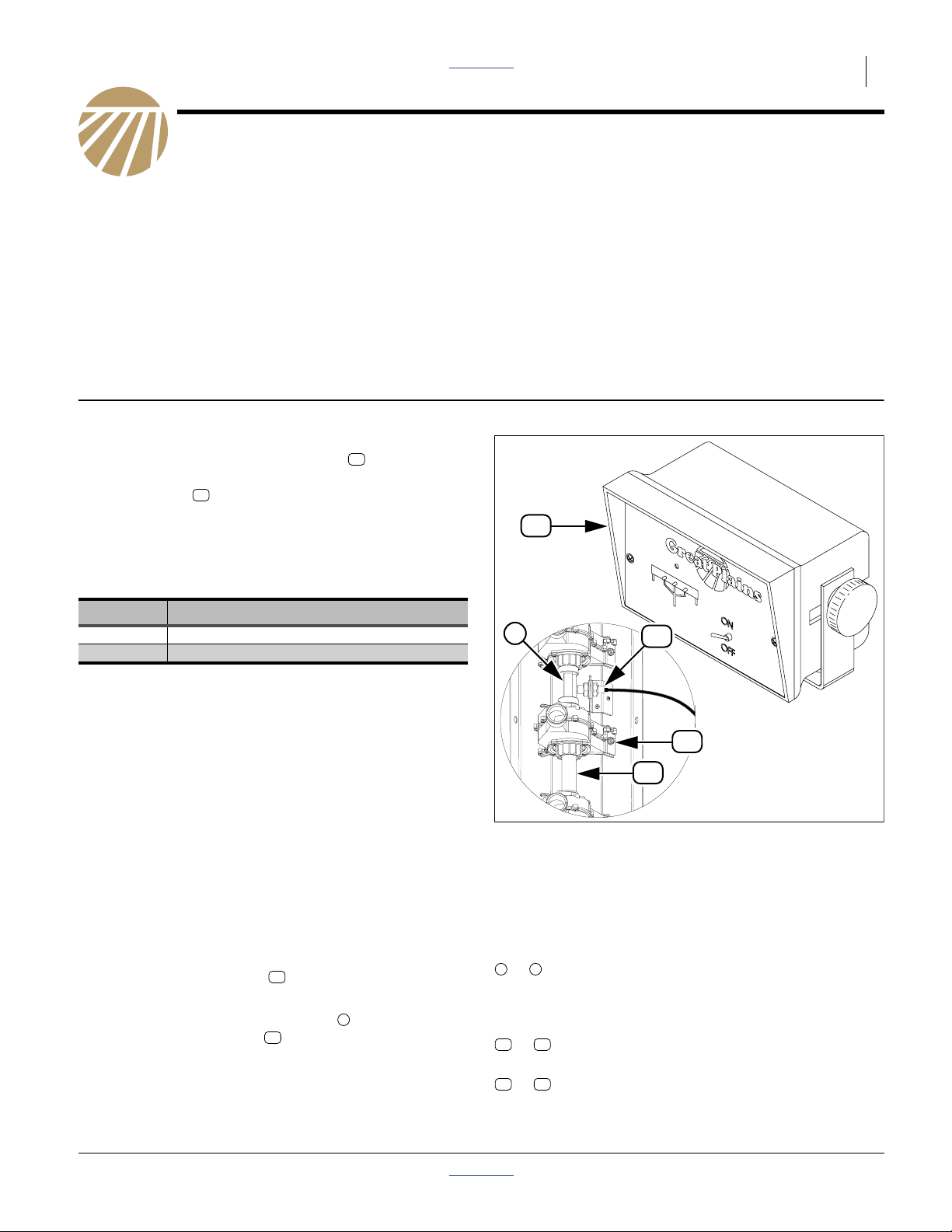
Refer to Figure 1
These instructions explain how to install a Loup Shaft
Monitor. The kit adds a rotation sensor to the main
seed box meter drive shaft of each drill box, and a
monitor console in the tractor.
In operation, when the main seed box shaft of any drill
box stops rotating for more than 20 seconds, an alarm
sounds in the tractor cab.
One kit updates one entire drill:
23
24
Part Lists Great Plains Manufacturing, Inc. 1
Note: Although the kit components may be mechanically
compatible with the Small Seeds Attachment, the
kits have not been tested in that application, and
the harnesses may be too short.
Note: The kits are compatible with current single-box
drills. Only one sensor would be used. The system
ignores disconnected channels.
23
Kits Kit Description
116-282A LOUP 2 CHANNEL SHAFT MONITOR
116-283A LOUP 3 CHANNEL SHAFT MONITOR
Tools Required:
• calibration crank and/or instructions for performing a
calibration on this model drill,
• basic hand tools, including drill and tap wrench,
•3⁄16 inch (#12, 4.8 mm) drill bit,
•1⁄4-20 tap, and #7 drill bit (or 5.1 mm),
• three1⁄4inch (6.3 mm) fasteners for installing the
console in the tractor cab, and
• a knife or saw capable of cutting hard rubber
(may not be required for larger row spacings).
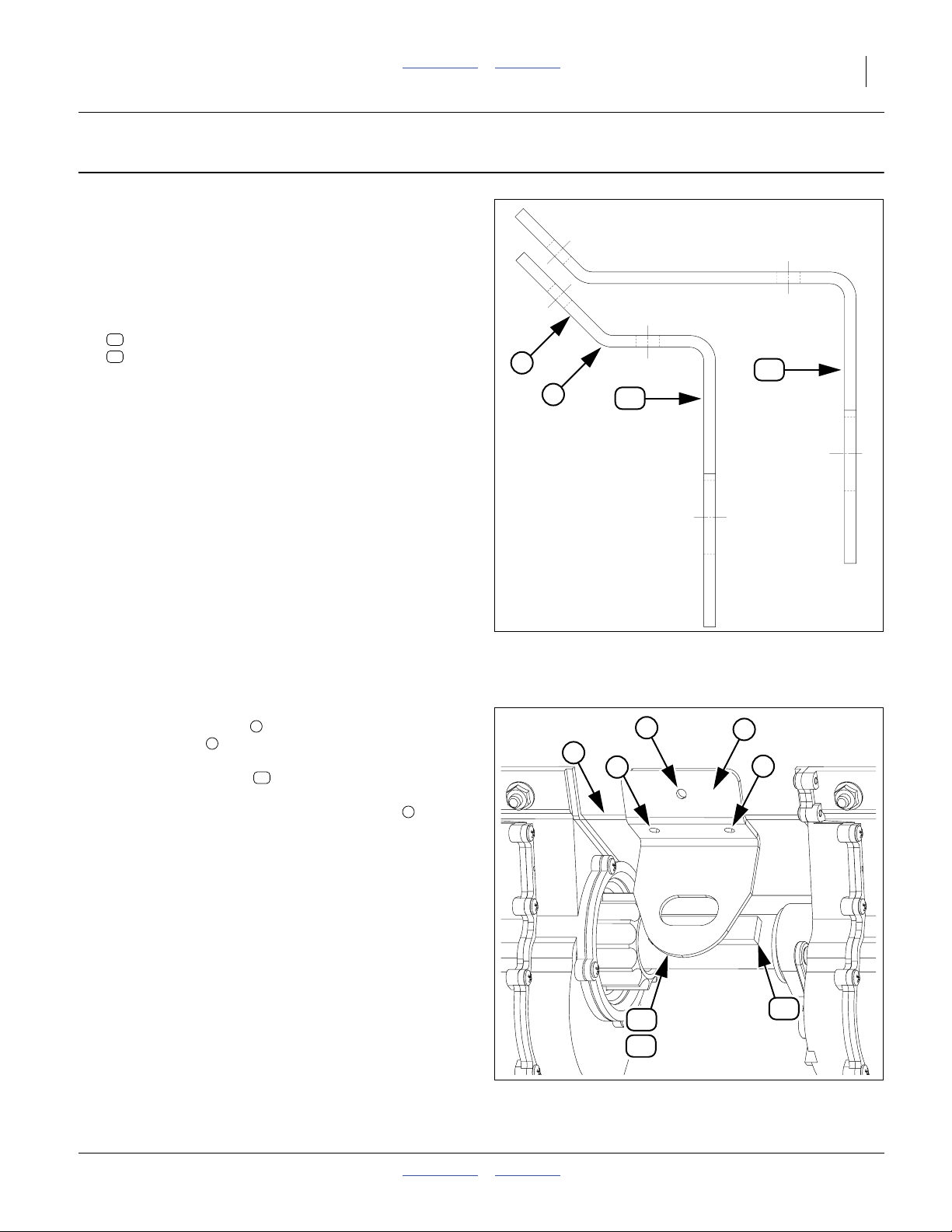
Compatibility Check
Refer to Figure 1
At one drill box, inspect the shaft passing through the
main seed box feeder cups . Verify that it is square
(not hexagonal) and is5⁄8inches on a side (15.9 mm).
The kit is compatible with bare shafts , or shafts inside
round plastic spacer tubes between meters. It is
compatible with large 817-075C (13⁄4inch flute width)
and small 817-094C (11⁄4inch) feeder cups.
54
1
51
1
24
54
51
Figure 1
3 Channel Console and Sensor
Notations and Conventions
Call-Outs
1 9
to Single-digit callouts identify components in
the currently referenced Figure. These
numbers may be reused for different items
from page to page.
21
11
to Two-digit callouts in the range 11 to 21
reference new parts from the list on page 13.
51 55
to Two-digit callouts in the range 51 to 55
reference existing parts.
18943
34210
© Copyright 2012 Printed 2013-08-27 Part Lists 116-284M
2 Great Plains Manufacturing, Inc. Front Page Part Lists LOUP 2/3 CHANNEL SHAFT MONITOR
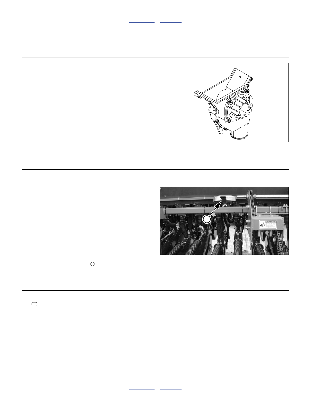
Identify Meter Type
1. Determine whether the drill has large or small feeder
cups.
Large cups, used on most drills still in production,
have a
13⁄4inch flute width,
and an approximate external width of
2 inches at the side walls.
Small cups, used on older drill designs have a
11⁄4inch flute width,
and an approximate external width of
11⁄2inches at the side walls.
Prepare the Drill
2. Move the drill to a location with adequate lighting,
and a clear surface beneath for recovery of any
falling parts.
3. If a folding model, unfold the drill. Consult the
Operator manual for details and safety
considerations.
4. Raise the drill or otherwise configure it so that the
meter drive shaft may be rotated while the drill is
stationary.
5. Install all locks or supports necessary to support the
drill while it is being worked on.
6. Shut off any tractor used to position the drill.
Refer to Figure 3
7. Settheseedratehandles , forall main seed boxes,
to 50 on the 0-to-100 scales.
2
Identify Mounting Positions
Figure 2
Meter Feeder Cup
2
Figure 3
Set Rate Handles to 50
17951
28066
8. Select one new:
27
540017 MAGNET, ADHESIVE BACKED, LARGE
Do not remove the release backing at this time.
On each main seed box, use the magnet to identify
locations between cups with the following attributes:
• close to drill center, on wing boxes,cups closest to the
center box section.
• not obstructed to the front by a seed rate handle, and
• adequate exposed surface on the drive shaft to place
the magnet - or adequate length of polymer tube to
provide cuts for magnet mounting.
9. Tag each location with a short length of tape on the seed box.
116-284M Front Page Part Lists 2013-08-27
Notes:
Gaps with lock collars generally provide exposed shaft.
Tube mounting requires that the tube be at least as long
as the magnet for surface mounting, and at least
11⁄2inches longer than the magnet for cut-away
mounting (see footnote on page 4).
Smaller row spacings may require reducing magnet
length, to not less than 13⁄4inch.
Install Magnets Front Page Part Lists Great Plains Manufacturing, Inc. 3
Install Magnets
Apply the instructions for “Tube Install” (step 10) or
“Shaft Face Install” (step 17 on page 4) for each
mounting position.
Shaft Face Install
If the location has a polymer tube over the shaft,
continue at “Tube Install” on page 4.
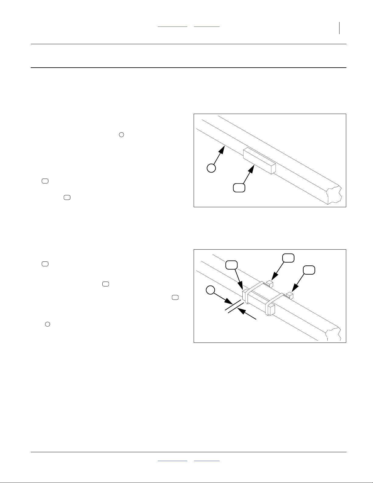
10. De-grease and dry the shaft .
11. Using the calibration crank or other means to rotate
the shaft so that two faces are at vertical, and two
are horizontal.
Refer to Figure 4
12. Select one new:
27
540017 MAGNET, ADHESIVE BACKED, LARGE
13. Before removing the release backing, check that the
magnet fits. If it does not fit, trim it as required,
keeping it longer than the minimum length specified
in the “Notes:” on page 2.
14. Remove the release backing film. Aligning with the
shaft center-line (and to the extent possible, in the
center of the cup-to-cup gap), apply the adhesive
side of the magnet to the shaft.
Refer to Figure 5
15. Select two new:
29
(These are the smaller ties)
27
770026 CABLE TIE
3
3
27
Figure 4
Magnet on Shaft
34212
29
27
29
Loosely install the ties at each end of the magnet,
so that when finally tightened, the ratchet end of the
tie will be on the shaft face opposite the magnet .
Position the ties so that the ends of the magnet are
exposed by at least dimension:
1
a
⁄4inch (6 mm).
Tighten the ties.
16. Continue with the next magnet location at step , or if
all magnets are installed, at “Drill Mounting Holes”
on page 5.
2013-08-27 Front Page Part Lists 116-284M
29
27
a
Figure 5
Magnet Secured by Ties
34212
4 Great Plains Manufacturing, Inc. Front Page Part Lists LOUP 2/3 CHANNEL SHAFT MONITOR
Tube Install
If the magnet location has a bare shaft, continue at
“Shaft Face Install” on page 3.
Tube install requires that tube rotation be coupled to
shaft rotation (it is normally free to spin). There are two
ways to accomplished this. The method enumerated
below may be easier. See footnotea for an alternative
method.
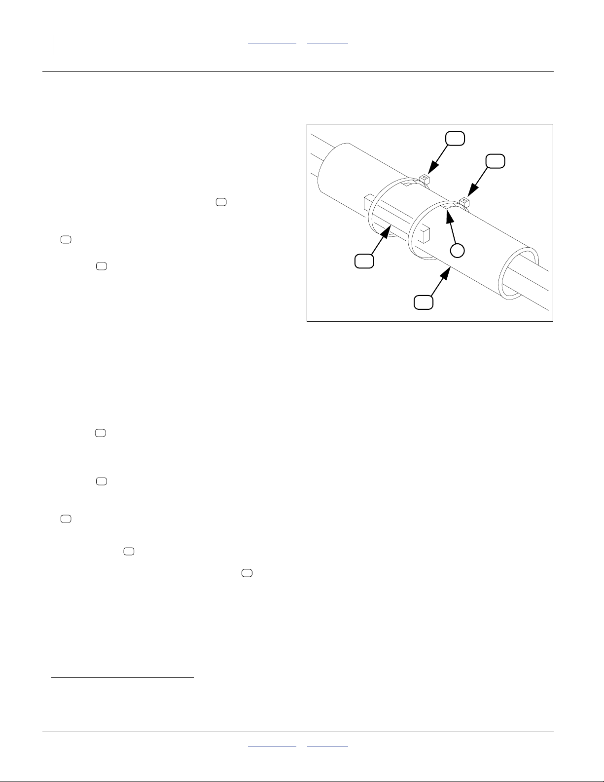
17. De-grease and dry the spacer tube .
51
Refer to Figure 6
18. Select one new:
27
540017 MAGNET, ADHESIVE BACKED, LARGE
19. Before removing the release backing, check that the
magnet fits. If it does not fit, trim it as required,
27
keeping it longer than the minimum length specified
in the “Notes:” on page 2.
20. Aligning with the shaft center-line (and to the extent
possible, in the center of the cup-to-cup gap), outline
the magnet position with a marker. Add a vertical
mark that is approximately
3
⁄8inch inside each end
of the outline.
21. Brace your arm against the seed box, and rotate the
tube while holding the marker at the vertical marks.
22. On the side of the tube opposite the magnet position,
make vertical cuts on the scribed lines.
27
51
Figure 6
Magnet on Tube
29
29
4
13198
Make the cuts wide enough for the ratchet ends of
the ties , and approximately1⁄4 of the tube
29
circumference. Be careful to not cut the shaft. Clean
away any cutting debris.
23. Remove the backing release film from the
magnet . Apply the adhesive side of the magnet to
27
the outlined area.
24. Select two new:
29
770026 CABLE TIE
(These are the smaller ties)
Install the ties at each end of the magnet, so that
29
when finally tightened, the ratchet end of the tie will
be on the shaft face opposite the magnet .
27
Tighten the ties so that they lay flat against a shaft
face in the cuts. This prevents independent tube
rotation.
25. Continue with the next magnet location at “Install
Magnets” on page 3, or if all magnets are installed,
at “Drill Mounting Holes” on page 5.
a. Cut-away Mounting: You may also cut or grind a slot in the tube, and mount the magnet directly on the shaft face, as in the
“Shaft Face Install” method. Be sure to use the cable ties to secure the magnet (ties may be tied around the tube, with or
without cuts).
116-284M Front Page Part Lists 2013-08-27
Drill Mounting Holes Front Page Part Lists Great Plains Manufacturing, Inc. 5
Drill Mounting Holes
Identify and Select Mount
Refer to Figure 7
(which is 1:1 scale
when printed at 100%
on U.S. letter size paper)
26. Based whether the drill has large or small cups,
select one of:
12
116-019D SHAFT SENSOR MOUNT (“Large”)
13
116-020D SMALL CUP SENSOR MOUNT (“Small”)
5
6
12
Large
Feeder Cup
Sensor Mount
13
Small
Feeder Cup
Sensor Mount
Refer to Figure 7 and Figure 8
27. With the short break of the mount forward and up,
and the break aligned on the break of the seed
box, position the center of the slotted hole over the
center of the magnet .
Mark the positions of the three small holes on the
seed box wall. Center-punch the positions.
28. Drill3⁄16 inch (#12, 4.8 mm) holes into the seed box
wall at each marked position.
29. Repeat step 27 and step 28 for each sensor position.
5
6
27
7
Figure 7
Identify Mount
7
6
7
13
12
Figure 8
Use Mount as Template
34213
5
7
27
34211
2013-08-27 Front Page Part Lists 116-284M
 Loading...