


Great Plains 116-138A User Manual
Operator’s/P arts Manual
24’ & 30’ Folding No-Till Drill
Harrow
Manufacturing, Inc.
P.O. Box 5060 ● Salina, Kansas 67402-5060
Read the Operator’s manual entirely. When you see this symbol, the subsequent in-
!
structions andwarnings are serious- follow without exception. Your life and the lives of
others depend on it!
© Copyright 1998 Printed
11/7/2006
13028
Cover illustration may show optional equipment not supplied with standard unit.
116-144M

General Information
Important Notice
Great Plains Manufacturing, Inc. provides this publication “as is” without warranty of any kind, either expressed or implied, while every precaution has been
taken in the preparation of this manual, Great Plains
Manufacturing,Inc. assumes no responsibility for errors
oromissions. Neither is any liability assumedfordamages resulting from the use of the information contained
This Operator’s Manual applies to the
Folding No-Till Harrow listed below:
116-137A 30’ 2 Section No-Till Harrow Assembly
116-138A 24’ 2 Section No-Till Harrow Assembly
Owner’s Information
herein. Great Plains Manufacturing, Inc. reservesthe
righttoreviseand improve its products as it sees fit. This
publicationdescribesthe state of this product at the time
of its publication, and may not reflect the product at all
times in the future.
Printed in the United States of America.
Name: _____________________________________
Address ____________________________________
City________________State ____ Zip ___________
Phone_______________________
Name of Dealership___________________________
Dealer’s Name _______________________________
Address ____________________________________
City________________State ____ Zip ___________
Phone ______________________
Date Purchased_______________
116-144M
11/7/06Great Plains Mfg., Inc.
Section 1 Assembly Instructions & Set-Up
Table of Contents
Section 1 Assembly Instructions & Setup . . . . . . -2
Torque Values Chart. . . . . . . . . . . . . . . . . . . . . . -2
Section 2 Parts . . . . . . . . . . . . . . . . . . . . . . . . . . . . . 3
Harrow Assembly Parts Drawing . . . . . . . . . . . . . 3
Assembly Instructions . . . . . . . . . . . . . . . . . . . . -2
Section 1
Assembly Instructions & Set-Up
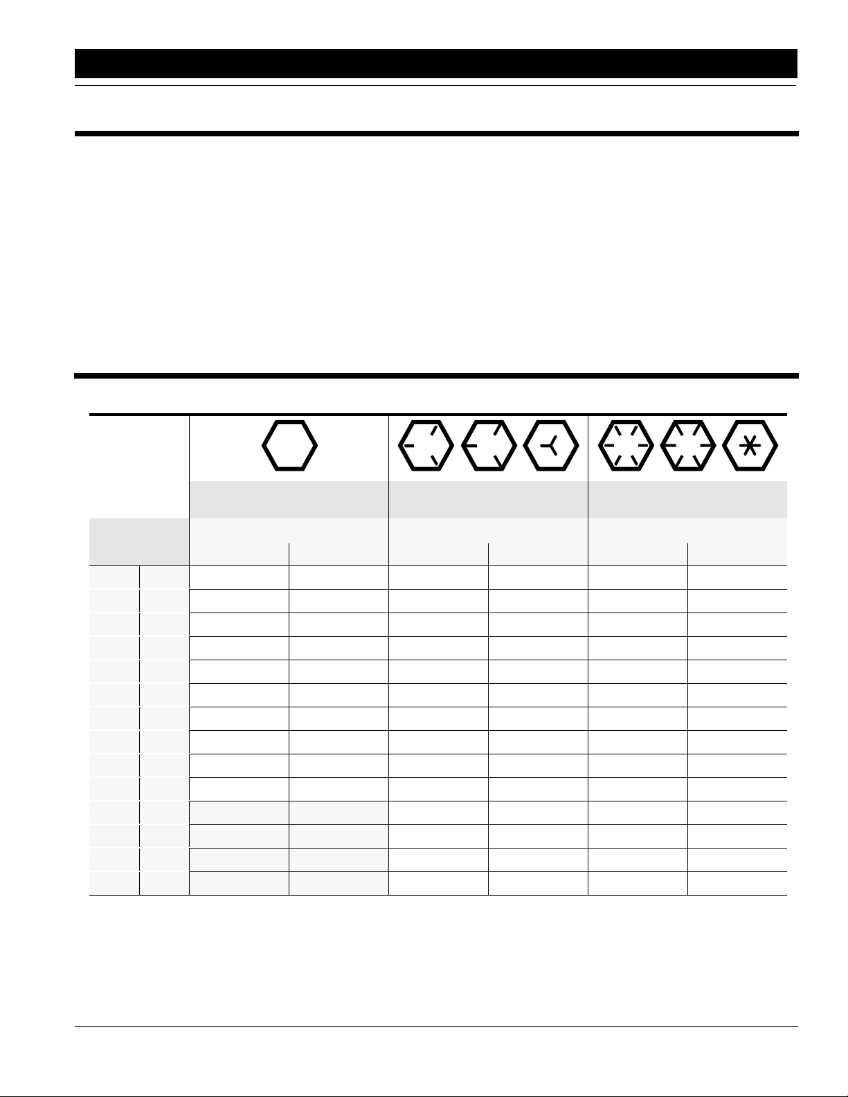
Torque Values Chart
Bolt head
identification
marks are as per
grade.
NOTE: Manufacturing marks will vary.
Bolt Size
inches mm Min. Max. Min. Max. Min. Max. Min. Max. Min. Max. Min. Max.
1/4" 6.35
5/16" 7.94
3/8" 9.53
7/16" 11.11
1/2" 12.70
9/16" 14.29
5/8" 15.88
3/4" 19.05
7/8" 22.23
1" 25.40
1 1/8" 25.58
1 1/4" 31.75
1 3/8" 34.93
1 1/2" 38.10
NOTE: Torque requirements listed above do not apply to self-locking nuts. For self-locking nuts increase the torque requirements listed by 15%.
Foot Pounds Newton-Meters Foot Pounds Newton-Meters Foot Pounds Newton-Meters
5 6 6.8 8.13 9 11 12.2 14.9 12 15 16.3 20.3
10 12 13.6 16.3 17 20.5 23.1 27.8 24 29 32.5 39.3
20 23 27.1 31.2 35 42 47.5 57.0 45 54 61.0 73.2
30 35 40.7 47.4 54 64 73.2 86.8 70 84 94.9 113.9
45 52 61.0 70.5 80 96 108.5 130.2 110 132 149.2 179.0
65 75 88.1 101.6 110 132 149.2 179.0 160 192 217.0 260.4
95 105 128.7 142.3 150 180 203.4 244.1 220 254 298.3 358.0
150 185 203.3 250.7 270 324 366.1 439.3 380 456 515.3 618.3
160 200 216.8 271.0 400 480 542.4 650.9 600 720 813.6 976.3
250 300 338.8 406.5 580 596 786.5 943.8 900 1080 1220.4 1464.5
* Thick nuts must be used with Grade 8 bolts
Grade 2 Grade 5 Grade 8*
800 880 1084.8 1193.3 1280 1440 1735.7 1952.6
1120 1240 1518.7 1681.4 1820 2000 2467.9 2712.0
1460 1680 1979.8 2278.1 2380 2720 3227.3 3688.3
1940 2200 2630.6 2983.2 3160 3560 4285.0 4827.4
11/7/06 Great Plains Mfg., Inc.
116-144M
--2