

Page 1
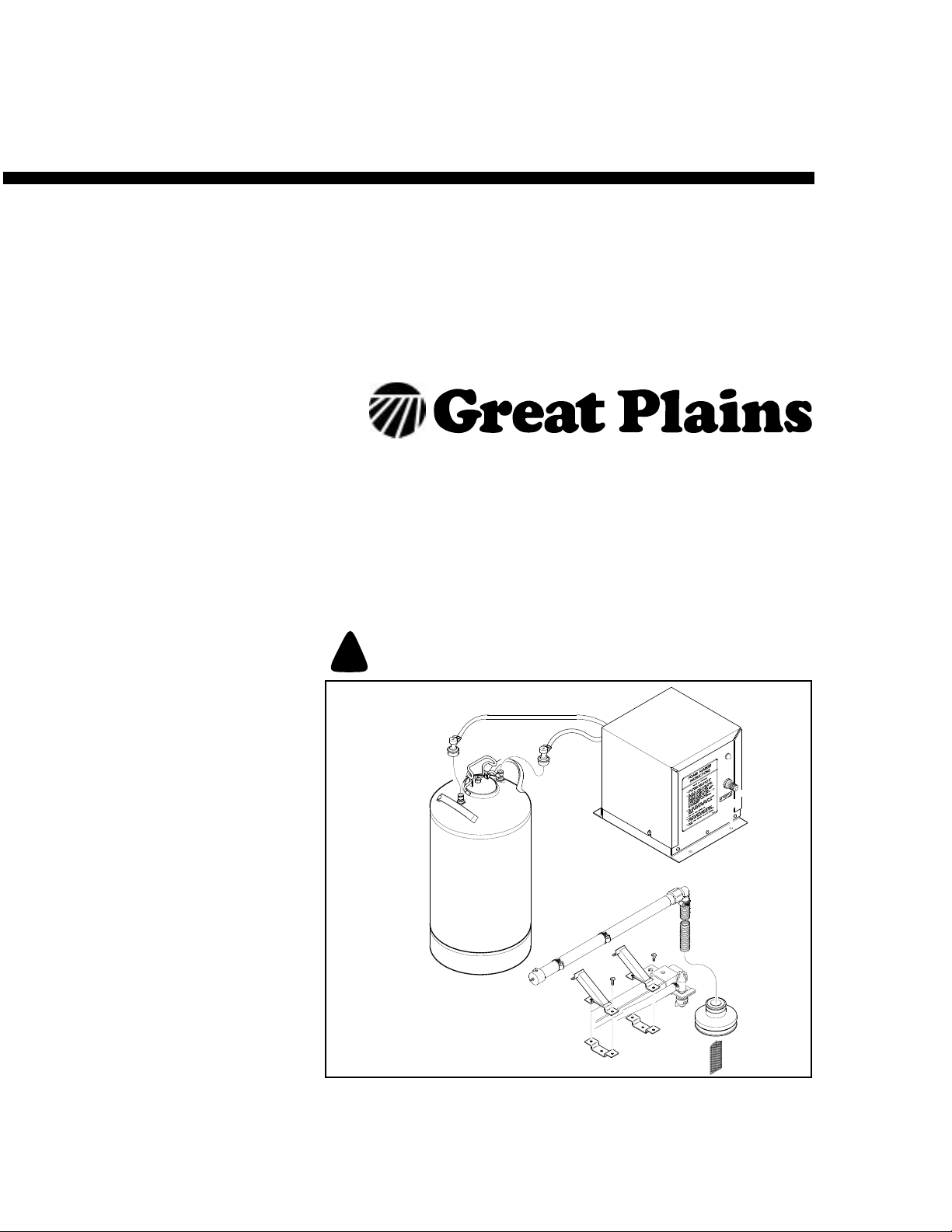
Operator’ s Manual
Serial Number S1347 and Above
Foam Marker
Manufacturing, Inc.
Read the operator’s manual entirely.Whenyouseethissymbol, the subsequent
instructions and warnings are serious - follow without exception. Your life and
!
the lives of others depend on it!
12453
Cover illustration may show optional equipment not supplied with standard unit.
© Copyright 1998 Printed 4/21/2003
500-033M-A
Page 2

Table of Contents
Important Safety Information . . . . . . . . . . . . . . . . . 1
Wear Protective Equipment . . . . . . . . . . . . . . . . 5
Handle Chemicals Properly . . . . . . . . . . . . . . . . 6
Safety Labels . . . . . . . . . . . . . . . . . . . . . . . . . . . 8
Introduction . . . . . . . . . . . . . . . . . . . . . . . . . . . . . . . 9
Intended Usage . . . . . . . . . . . . . . . . . . . . . . 9
Models Covered . . . . . . . . . . . . . . . . . . . . . . 9
Using This Manual . . . . . . . . . . . . . . . . . . . . . . . 9
Definitions. . . . . . . . . . . . . . . . . . . . . . . . . . . 9
Owner Assistance. . . . . . . . . . . . . . . . . . . . . . . . 9
Preparation and Setup . . . . . . . . . . . . . . . . . . . . . 10
Tandem Axle Sprayer / Foam Marker Assembly
Instructions and Set-Up . . . . . . . . . . . . . . . . . . 10
Single Axle Sprayer / Foam Marker Assembly
Instructions and Set-Up . . . . . . . . . . . . . . . . . . 11
Tractor Mount Sprayer / Foam Marker Assembly
Instructions and Set-Up . . . . . . . . . . . . . . . . . . 12
200/300 Gallon 3-Point Mounted Sprayer / Foam.
Marker Assembly Instructions and Set-Up . . . . 12
Tractor Requirements . . . . . . . . . . . . . . . . . . . . 13
Operating Instructions . . . . . . . . . . . . . . . . . . . . . 14
Basic Foam Marker Operating Procedures. . . . 14
Filling Foam Tank . . . . . . . . . . . . . . . . . . . . 14
Operating the Foam Control Valve . . . . . . . 14
Operating Checklist. . . . . . . . . . . . . . . . . . . . . . 14
Adjustments. . . . . . . . . . . . . . . . . . . . . . . . . . . . . . 15
Field Adjustments . . . . . . . . . . . . . . . . . . . . . . . 15
Foam Marker . . . . . . . . . . . . . . . . . . . . . . . 15
Foam Marker Preparation. . . . . . . . . . . . . . . . . 15
General Notes for Field Operation . . . . . . . 15
Storage. . . . . . . . . . . . . . . . . . . . . . . . . . . . . . . . . . 15
Troubleshooting. . . . . . . . . . . . . . . . . . . . . . . . . . . 16
Appendix . . . . . . . . . . . . . . . . . . . . . . . . . . . . . . . . 17
Torque Values Chart . . . . . . . . . . . . . . . . . . . . . 17
Warranty . . . . . . . . . . . . . . . . . . . . . . . . . . . . . . 18
© Copyright 1998Allrights Reserved
Great Plains Manufacturing, Inc. provides this publication“as is” without warranty of any kind, either expressed or implied. While every precaution has been takenin the
preparationofthismanual,GreatPlainsMan uf acturing,Inc.assumesno responsibility for errorsoromissions.Neither is any liabilityassumedfordamages resulting from
theuseof the information contained herein. Great Plains Manufacturing,Inc. reservestheright to reviseandimproveits products as it sees fit. This publication describes
the state of this product at the time of its publication, and may not reflect the product in the future.
Great Plains Manufacturing, Incorporated Trademarks
The following are trademarks of Great Plains Mfg., Inc.: Application Systems, Ausherman, Land Pride, Great Plains
All other brands and product names are trademarks or registered trademarks of their respective holders.
Printed in the United States of America.
4/21/2003
500-033M-A
Page 3

Important Safety Information
Look for Safety Symbol
The SAFETY ALERT SYMBOL indicates there is
apotential hazard to personal safetyinvolvedand
extrasafety precaution must be taken. When you
see this symbol, be alert and carefully read the
message that follows it. In addition to design and
configuration of equipment, hazard control and
accident prevention are dependent upon the
awareness, concern, prudence and proper training of personnel involved in the operation,
transport, maintenance and storage of
equipment.
Important Safety Information
!
1
Be Aware of Signal Words
Signal words designate a degree or level of hazard seriousness.
DANGER indicates an imminently hazardous situation which, if not avoided, will result in death or
serious injury. This signal word is limited to the
most extreme situations, typically for machine
components that, for functional purposes, cannot
be guarded.
WARNINGindicates a potentially hazardous situationwhich, if not avoided,could resultin death or
serious injury, and includes hazards that are exposed when guards are removed. It may also be
used to alert against unsafe practices.
CAUTION indicates a potentially hazardous situation which, if not avoided,may result in minor or
moderate injury. It may also be used to alert
against unsafe practices.
DANGER
!
WARNING
!
CAUTION
!
4/21/2003
500-033M-A
Page 4
Foam Marker
2
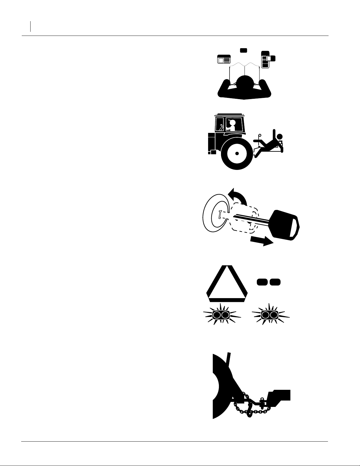
Be Familiar with Safety Decals
▲ Read and understand “Safety decals,” thor-
oughly.
▲ Read all instructions noted on the decals.
Keep Riders Off Machinery
Riders obstruct the operator’s view.Riders could
be struck by foreign objects or thrown from the
machine.
▲ Never allow children to operate equipment.
▲ Keep all bystanders away from machine dur-
ing operation.
Use Safety Lights and Devices
Slow-moving tractors and towed implements can
create a hazard when driven on public roads.
They are difficult to see, especially at night.
OFF
▲ Use flashing warning lights and turn signals
whenever driving on public roads.
▲ Use lights and devices provided with imple-
ment.
Use A Safety Chain
▲ Use a safety chain to help control drawn
machinery should it separate from tractor
drawbar.
▲ Use a chain with a strength rating equal to or
greater than the gross weight of towed
machinery.
▲ Attach chain to tractor drawbar support or
other specified anchor location. Allow only
enough slack in chain to permit turning.
▲ Replace chain if any links or end fittings are
broken, stretched or damaged.
▲ Do not use safety chain for towing.
500-033M-A
4/21/2003
Page 5

Transport Machinery Safely
Maximum transport speed for implement is 20
mph. Some rough terrains require a slower
speed.Sudden brakingcan cause atowed loadto
swerve and upset.
▲ Do not exceed 20 mph. Never travel at a
speed which does not allow adequate control
of steering and stopping. Reduce speed if
towed load is not equipped with brakes.
▲ Comply with state and local laws.
▲ Do not tow an implement that, when fully
loaded, weighs more than 1.5 times the weight
of towing vehicle.
▲ Carry reflectors or flags to mark implement in
case of breakdown on the road.
▲ Keep clear of overhead power lines and other
obstructions when transporting.
Important Safety Information
3
▲ Do not fold or unfold the sprayer while the trac-
tor is moving.
Avoid High Pressure Fluids
Escaping fluid under pressure can penetrate the
skin, causing serious injury.
▲ Avoid the hazard by relieving pressure before
disconnecting hydraulic lines.
▲ Use a piece of paper or cardboard, NOT
BODY PARTS, to check for suspected leaks.
▲ Wear protective gloves and safety glasses or
goggles when working with hydraulic systems.
▲ If an accident occurs, see a doctor immedi-
ately. Any fluid injected into the skin must be
surgically removed within a few hours or gangrene may result.
4/21/2003
500-033M-A
Page 6

Foam Marker
4
Practice Safe Maintenance
▲ Understand procedure before doing work. Use
proper tools and equipment. Refer to this manual for additional information.
▲ Work in a clean, dry area.
▲ Put tractor in park, turn off engine, and
remove key before performing maintenance.
▲ Make sure all moving parts have stopped and
all system pressure is relieved.
▲ Allow sprayer to cool completely.
▲ Disconnect battery ground cable (-) before
servicing or adjusting electrical systems or
before welding on sprayer.
▲ Inspect all parts. Make sure parts are in good
condition and installed properly.
▲ Remove buildup of grease, oil or debris.
▲ Remove all tools and unused parts from
sprayer before operation.
Prepare for Emergencies
▲ Be prepared if a fire starts.
▲ Keep a first aid kit and fire extinguisher handy.
▲ Keep emergency numbers for doctor, ambu-
lance, hospital and fire department near
phone.
Tire Safety
Tire changing can be dangerous and should be
performed by trained personnel using correct
tools and equipment.
OFF
911
▲ When inflating tires, use a clip-on chuck and
extension hose long enough for you to stand
to one side–not in front of or over tire assembly. Use a safety cage if available.
▲ When removing and installing wheels, use
wheel-handling equipment adequate for
weight involved.
500-033M-A
4/21/2003
Page 7

Wear Pr otective Equipment
Great Plains advises all users of chemical pesticides or
herbicides to use the following personal safety
equipment.
▲ Waterproof, wide-brimmed hat.
▲ Waterproof apron.
▲ Face shield, goggles or full face respirator.
▲ Goggles with side shields or a full face respirator is
required if handling or applying dusts, wettable powders, or granules or if being exposed to spray mist.
▲ Cartridge-type respirator approved for pesticide
vapors unless label specifies another type of respirator.
▲ Waterproof, unlined gloves. Neoprene gloves are
recommended.
Important Safety Information
5
▲ Cloth coveralls/outer clothing changed daily; water-
proof items if there is a chance of becoming wet with
spray.
▲ Waterproof boots or foot coverings.
▲ Do not wear contaminated clothing. Wash protective
clothing and equipment with soap and water after
each use. Personal clothing must be laundered separately from household articles.
▲ Clothing contaminated with certain pesticides must
be destroyed according to state and local regulations. Read chemical label for specific instructions.
▲ Wear clothing and equipment appropriate for the job.
Avoid loose-fitting clothing.
▲ Prolonged exposure to loud noise can cause hear-
ing impairment or loss. Wear suitable hearing protection such as earmuffs or earplugs.
▲ Avoid wearing radio headphones while operating
machinery. Operating equipment safely requires the
full attention of the operator.
4/21/2003
500-033M-A
Page 8

Foam Marker
6
Handle Chemicals Properly
▲ Read and follow chemical manufacturer’s
instructions.
▲ Wear protective clothing.
▲ Handle all chemicals with care.
▲ Agricultural chemicals can be dangerous.
Improper use can seriously injure persons,
animals, plants, soil and property.
▲ Inhaling smoke from any type of chemical fire
is a serious health hazard.
▲ Store or dispose of unused chemicals as
specified by the chemical manufacturer.
▲ Before adding chemical to the tank, make
sure tank is at least half full. Do not pour concentrate into an empty tank.
▲ Never leave fill hose attached to the sprayer
after filling tank. Chemicals in tank can siphon
out of tank and contaminate freshwater
source.
▲ Always keep hand-wash tank filled with clean
water and have soap available in case of an
emergency. Immediately and thoroughly flush
any area of the body that is contaminated by
chemicals.
▲ Spray only with acceptable wind conditions.
Wind speed must be below 5 mph. Make sure
wind drift of chemicals will not affect any surrounding land, people or animals.
▲ Never wash out the sprayer tank within 100
feet of any freshwater source or in a car wash.
▲ Rinse out the tank. Spray rinse water on last
field sprayed.
▲ Do not touch sprayer components with mouth
or lips.
▲ If chemical is swallowed, carefully follow the
chemical manufacturer’s recommendations
and consult with a doctor.
▲ If persons are exposed to a chemical in a way
that could affect their health, consult a doctor
immediately with the chemical label or container in hand. Any delay could cause serious
illness or death.
▲ Dispose of empty chemical containers prop-
erly. By law rinsing of the used chemical container must be repeated three times. Puncture
the container to prevent future use. An alternative is to jet-rinse or pressure rinse the container.
▲ Wash hands and face before eating after
working with chemicals. Shower as soon as
spraying is completed for the day.
500-033M-A
4/21/2003
Page 9

Safety At All Times
Thoroughly read and understand the instructions
in this manual before operation. Read all instructions noted on the safety decals.
▲ Be familiar with all machinery functions.
▲ Operate machinery from the driver’s seat only.
▲ Do not leave sprayer unattended with tractor
engine running.
▲ Do not dismount a moving tractor. Dismount-
ing a moving tractor could cause serious injury
or death.
▲ Do not stand between the tractor and sprayer
during hitching.
▲ Keep hands, feet and clothing away from
power-driven parts.
Important Safety Information
7
▲ Wear snug-fitting clothing to avoid entangle-
ment with moving parts.
▲ Watch out for wires, trees, etc., when folding
and raising sprayer. Make sure all persons are
clear of working area.
▲ Do not turn tractor too tightly, causing sprayer
to ride up on wheels. This could cause personal injury or equipment damage.
▲ Use only water without pesticides added to
calibrate the sprayer. Do not exceed the calibrated sprayer speed and pressure when
operating.
▲ When using a PTO pump, be sure that PTO
shield is in place on the tractor, PTO coupler
bolts are torqued to the correct specification,
and torque bar is properly chained to tractor
drawbar.
▲ Spray with the boom in the unfolded position
only.
▲ The boom has many pinch points during field
operation and folding. Keep all bystanders
away.
4/21/2003
500-033M-A
Page 10

Foam Marker
8
Safety Labels
Your implement comes equipped with all safety labels in place.
They were designed to help you safely operate your implement.
1. Read and follow label directions.
2. Keep all safety labels clean and legible.
3. Replace all damaged or missing labels.
4. Some new equipment installed during repair require safety
labels to be affixed to the replaced component as specified
by the manufacturer. When ordering new components make
sure the correct safety labels are included in the request. To
order new labels go to your Great Plains dealer.
5. Refer to this section for proper label placement.
To install new labels:
a. Clean the area the label is to be placed.
b. Peel backing from label. Press firmly on surface
being careful not to cause air bubbles under label.
10044
10213
818-328C
Warning! Pressure Relief Valve Information
818-384C
Caution! General Safety Precautions for Foam Concentrate Use.
500-033M-A
4/21/2003
Page 11

Introduction
Introduction
9
GreatPlains welcomesyouto itsgrowingfamilyof
newproduct owners.ThisFoam Marker hasbeen
designedwith care and built byskilledworkers using quality materials. Proper setup, maintenance
and safe operating practices will help you get
years of satisfactory use from the machine.
Intended Usage
Use this Foam Marker as part of a pressurized
sprayersystem to apply liquid pesticides, herbicides or fertilizers to production-agriculture crops
only. Do not modify sprayer for use with attachmentsother than those approvedbyGreat Plains.
Models Covered
Foam Marker S/N S1347 and above.
Using This Manual
This manual will familiarize you with safety, assembly, operation, adjustments, troubleshooting
and maintenance. Read this manual and follow
the recommendations to help ensure safe and efficient operation.
The information in this manual is current at printing. Some parts may change to assure top
performance.
Definitions
The following terms are used throughout this
manual.
Right-hand and left-hand as used in this manual
are determined by facing the direction the machine will travel while in use unless otherwise
stated.
Owner Assistance
If you need customer service or repair parts, contact a Great Plains dealer. They have trained
personnel, repair parts and equipment specially
designed for Great Plains products.
Your machine’sparts were specially designed and
should only be replaced with Great Plains parts.
Alwaysuse the serial and model number when ordering parts from your Great Plains dealer.
Record your model and serial number here for
quick reference:
Model Number:__________________________
Serial Number: ___________________________
Your Great Plains dealer wants you to be satisfied
with your new machine. If you do not understand
anypart of this manualor are not satisfied with the
service received, please take the following
actions.
1. Discuss the matter with your dealership service manager. Make sure they are aware of
any problems so they can assist you.
2. If you are still unsatisfied, seek out the owner
or general manager of the dealership.
3. For further assistance write to:
Product Support
Great Plains Mfg. Inc., Service Department
PO Box 5060
Salina, KS 67402-5060
4/21/2003
IMPORTANT: A crucial point of information related to the preceding topic. For safe and correct operation, read and follow the directions
provided before continuing.
NOTE: Useful information related to the preceding topic.
500-033M-A
Page 12

Foam Marker
10
Preparation and Setup
Tandem Axle Sprayer / Foam Marker
Assembly Instructions and Set-Up
Refer to Figure 1
1. Mount the support brackets (1) and (2) on the right
walkboard with 3/8" x 1" long bolts (3), flat washers,
and flange nuts required.
2. Mount the foam marker box (4) and the foam tank
base (6) on the support bracketswith 3/8" x 1" long
bolts and flange nuts required.
3. Secure the foam tank (5) to the foam tank base (6)
with the hose clamp (7) provided.
4. Attach a section of the clear hose from the hose
barb on the foam marker box(4) labeled "AIRTANK
IN" to the hose barb on the foam tank (5) that has a
white coupling. In a similar manner,attach a section
of the clear hose from the hose barb on the foam
marker box (4) labeled "FOAM TANK OUT" to the
blackcoupler on the tank. Attach the hoses with the
hose clamps provided.
Refer to Figure 2
5. Attach the foamgeneratorcylinder (1) onboth boom
wings using the foam cylinder brackets(2), the 1/4"
screws and flange nuts. Make sure that the hose
barb (9) is on the top side of the cylinder. Use the
hose clamps (3) to attach the foam generator cylinder brackets.
Important: Mount the foam generator cylinders on
the back side of the boom. F ailure to do so may
cause damage to the foam generator cylinders if the
boom strikes an object.
6. In your foammarkerkit there are some C-clips (4) to
help route the foam marker hose. These C-clips are
attached underneath the top side of the nozzle
check valve brackets (5). Assemble the T-clip (6)
and screw (7) to the C-clips. Loosen the nozzle
check valve brackets (5), slide the assembled
C-clips under the bracket and retighten the nozzle
checkvalvebrackets. Assemblethe C-clips uniformly across the boom.
Figure 1
Tandem Axle Foam Marker Assembly Illustration
500-033M-A
11997
Figure 2
Foam Generator Assembly Illustration
11998
7. Enclosed in the foam marker kit is some 1/4" clear
vinyl hose. Route a section of hose from the "AIR
LEFT" hose barb on the foam marker box to the
hose barb (8) that comes out the end of the foam
generatorcylinderon theleft boomwing. Routevinyl
4/21/2003
Page 13

Preparation and Setup
11
hose with boom feeder hose through boom pivot areas to ensure adequate hose length. Attach vinyl
hose to boom feeder hose with tie straps provided,
being careful not to pinch the vinyl hose. Before you
cut the hose, make sure that there is enough length
on the hose so that the boom can be completely
raised an lowered without stretching the hose. Position the hose through the T-clips (6) along the boom
wing.Pull up the tabs on the T-clips and position the
hose in the T-clips after the hose has been routed.
8. Route a section of hose from the "FOAM LEFT"
hose barb on the foam marker box to the hose barb
(9) that comes out the side of the foam generator
cylinderon the leftboom wing. Routevinyl hosewith
boom feeder hose through boom pivot areas to ensure adequate hose length. Attach vinyl hose to
boom feeder hose with tie straps provided, being
careful not to pinch the vinyl hose. As before, make
sure that there is enough length on the hose so that
the boom can be completely raised and lowered
without stretching the hose. Position the hose
through the other side of the T-clip (6) along the
boom wing.
9. Repeat steps 6, 7 and 8 for the right boom wing.
white coupling. In a similar manner,attach a section
of the clear hose from the hose barb on the foam
marker box (5) labeled "FOAM TANK OUT" to the
blackcoupler on the tank. Attach the hoses with the
hose clamps provided.
5. Follow the instructions step 5 through step 10 on
page 10 to attach the foam generator cylinders.
Refer to Figure 1, on page 10
10. Attach the foam marker extension cord (8) from the
foammarker box (4) to the foammarker plug on the
control box.
Note: If your sprayer does not have the manual control system with the Application Systems control box,
youwill need to purchase the 502-031A foammarker
kit which includes a small switch box to control the
foam marker.
Single Axle Sprayer / Foam Marker
Assembly Instructions and Set-Up
Refer to Figure 3
1. Mount the foam tank base (2) on the walkboard with
thetwo3/8" x 1" long bolts (1) and one 3/8" x 2"long
bolt with the flat washers (6) and flange nuts (7) required.
2. Mount the foam marker box (5) onto the expanded
metal with four 3/8" x 1" long bolts (1), flat washers
(6) and flange nuts (7).
3. Secure the foam tank (4) to the foam tank base (2)
with the hose clamp (3) provided.
11996
Figure 3
Single Axle Foam Marker Assembly Illustration
4. Attach a section of the clear hose from the hose
barb on the foam marker box(5) labeled "AIRTANK
IN" to the hose barb on the foam tank (4) that has a
4/21/2003
500-033M-A
Page 14

Foam Marker
12
Tractor Mount Sprayer / Foam Marker
Assembly Instructions and Set-Up
Refer to Figure 4
1. Mount the foam tank base (1) on the tank bracket
with two 3/8" x 1" long bolts (2), flat washers, and
flange nuts required.
2. Mount the foam marker box (4) and the foam tank
base (6) on the support brackets with 3/8" x 1" long
bolts and flange nuts required.
3. Secure the foam tank (5) to the foam tank base (6)
with the hose clamp (7) provided.
4. Attach a section of the clear hose from the hose
barb on the foam marker box(4) labeled "AIRTANK
IN" to the hose barb on the foam tank (5) that has a
white coupling. In a similar manner,attach a section
of the clear hose from the hose barb on the foam
marker box (4) labeled "FOAM TANK OUT" to the
blackcoupler on the tank. Attach the hoses with the
hose clamps provided.
5. Follow the instructions step 5 through step 10 on
page 10 to attach the foam generator cylinders.
200/300 Gallon 3-Point Mounted
Sprayer / Foam Marker Assembl y
Instructions and Set-Up
Refer to Figure 5
1. Mount the support brackets (1) and (2) on the right
walkboard with 3/8" x 1" long bolts (3), flat washers,
and flange nuts required.
2. Mount the foam marker box (4) and the foam tank
base (6) on the support bracketswith 3/8" x 1" long
bolts and flange nuts required.
3. Secure the foam tank (5) to the foam tank base (6)
with the hose clamp (7) provided.
4. Attach a section of the clear hose from the hose
barb on the foam marker box(4) labeled "AIRTANK
IN" to the hose barb on the foam tank (5) that has a
white coupling. In a similar manner,attach a section
of the clear hose from the hose barb on the foam
marker box (4) labeled "FOAM TANK OUT" to the
blackcoupler on the tank. Attach the hoses with the
hose clamps provided
5. Follow the instructions step 5 through step 10 on
page 10 to attach the foam generator cylinders.
Figure 4
Tractor Mount Foam Marker Assembly Illustration
500-033M-A
12442
13264
Figure 5
3-Point Sprayer Foam Marker Assembly Illustration
4/21/2003
Page 15

Tractor Requirements
Refer to Figure 6
To operate your Great Plains Foam Marker, a tractor using a 12 volt electrical system must be used.
Note: If your Sprayer does not have the manual control system with the Application Systems control box,
youwill need to purchase the 502-031A foammarker
kit which includes a small switch box to control the
foam marker.
11984
Preparation and Setup
Figure 6
Switch Box for Foam Marker Kit
13
4/21/2003
500-033M-A
Page 16

Foam Marker
14
Operating Instructions
Basic Foam Marker Operating Procedures
Filling Foam Tank
1. Open the pressurerelief valveon the topof the foam
tank before removing the tank lid. This will equalize
the pressure on the inside of the foamtank with that
of the atmosphere.
!
CAUTION
Open the pressurerelief valve and allow all pressure to be released before the tank cap is removed. Failure to do so may
cause bodily injury.
2. Mix 1/2 to 1 quart of foam marker concentrate in the
10 gallon foam tank. Use an Application Systems
foam concentrate quart container to measure the
correct volume of foam concentrate. For smaller
quantities,the ratio is 1 1/2 to 3 ounces per gallon of
water.
3. Fill the tank with water. With hard water, add more
foamingconcentrate.The lidmust besealed airtight
for proper foaming.
4. Check the condition of hoses and connections frequently.
11984
Figure 7
Foam Control Valve
Operating Checklist
Operating the Foam Control Valve
1. Turn the foam marker on.
Refer to Figure 7
2. Open the foamcontrol valveon the foamcontrolbox
gradually, allowing several minutes for the liquid to
feed into the foaming cylinder on the boom.
3. Adjust the foam control valveto the desired output.
Pre-Assembly Checklist
Check the volume of soap in the foam marker tank.
Check if the power light is on when the marker is turned on.
Check the foam marker’ s 1/4" clear hose f or kinking.
Make sure the marker’s components are securely fastened.
500-033M-A
4/21/2003
Page 17

Adjustments
Adjustments
15
Field Adjustments
Foam Marker
The foam marker should be set so that when a pass is
makein the field with the foammarker on, you shouldbe
able to clearly see the foam marker on the next pass. If
too much foam is being applied, you will have to fill up
the foam marker more often. The rate of foam coming
out of the foam marker can be adjusted with the foam
control valve, refer to Figure 7, page 14.
If youfind thatthe dropsof foamare not large enough to
see, a foam marker bell can be placed on the end of the
drop hose to make larger foamdrops. Referto the parts
manual on page 1-1 to purchase a foam marker bell.
Foam Marker Preparation
General Notes for Field Operation
1. Check to make sure the foam marker is securely attached to its mount, and the foam generator cylinders are securely fastened to the boom.
2. Check the volume of soap in the foamtank to make
surethere is enough soap tooperate the foammarker for the time you will be spraying.
3. Check the foammarkerclear hose that routes along
the boom to be sure her are no kinks in the hose.
4. Turn on the foammarker by turning the foammarker
switchto the left orrightandsee if the powerlighton
the foam marker lights up. If the light does not turn
on, the foam marker does not have power. Check
the wiring harness plug.
5. DO NOT substitute other substances for the foam
marker concentrate. The foam marker concentrate
is specially formulated for the foam marker to produce high quality, long lasting foam. Other soap formulas are not made for this purpose.
Storage
Storage
1. Empty the left over sop in the foam marker tank.
2. Open the foam marker control valve full open and
operate the foam marker on both wings until all the
soapy water is purged from the system.
3. Inspect all parts of the foam marker for wear and
rust. Repair and paint parts as necessary. Replace
anydecals thatare worn orhard to read.Parts, paint
and decals may be obtained for your marker from
your Application Systems Dealer.
4/21/2003
500-033M-A
Page 18

Foam Marker
16
Troubleshooting
Foam Marker
Light* Reading
No Foam
{Power Light OFF}
No Foam
{Power Light ON}
Problem Area Specific Checks Corrections
Electrical Power
Source
Foam Marker
Hoses
Electric Solenoids 1. Check that all three sole-
Foam Tank Lid 1. Lid not fastened properly
Compressor 1. Compressor not running
1. Plugs on wiring harness
2. Faulty switch on control box
1. Foam marker hoses kinked
or pinched
noids are functioning
2. Check that all three solenoids are functioning
2. Pressure relief is on
2. Compressor not running
1. Plug in the connections on
the wiring harness
2. Check connections on
switch, or replace switch if
faulty
1. Use cableties to secure the
hose so it will not pinch
1. Correct electrical connectors on solenoids
2. Adjust nut on the top of the
solenoid so it will operate
1. Install the lid squarely on
tank
2. Turn off pressure relief on
the lid
1. Correct electrical connections
2. Replace compressor
*The foam marker light is located on the foam marker box, Figure 8.
13266
500-033M-A
Figure 8
Foam Marker Light
4/21/2003
Page 19

Appendix
Torque V alues Chart
Bolt Head Identification
Appendix
Bolt Head Identification
17
Bolt Size
(Inches)
1
in-tpi
1/4" - 20 7.4 5.6 11 8 16 12 M 5 X 0.8 4 3 6 5 9 7
1/4" - 28 8.5 6 13 10 18 14 M 6 X 1 7 5 11 8 15 11
5/16 - 18 15 11 24 17 33 25 M 8 X 1.25 17 12 26 19 36 27
5/16" - 24 17 13 26 19 37 27 M 8 X 1 18 13 28 21 39 29
3/8" - 16 27 20 42 31 59 44 M10 X 1.5 33 24 52 39 72 53
3/8" - 24 31 22 47 35 67 49 M10 X 0.75 39 29 61 45 85 62
7/16" - 14 43 32 67 49 95 70 M12 X 1.75 58 42 91 67 125 93
7/16" - 20 49 36 75 55 105 78 M12 X 1.5 60 44 95 70 130 97
1/2" - 13 66 49 105 76 145 105 M12 X 1 90 66 105 77 145 105
1/2" - 20 75 55 115 85 165 120 M14 X 2 92 68 145 105 200 150
9/16" - 12 95 70 150 110 210 155 M14 X 1.5 99 73 155 115 215 160
9/16" - 18 105 79 165 120 235 170 M16 X 2 145 105 225 165 315 230
5/8" - 11 130 97 205 150 285 210 M16 X 1.5 155 115 240 180 335 245
5/8" - 18 150 110 230 170 325 240 M18 X 2.5 195 145 310 230 405 300
3/4" - 10 235 170 360 265 510 375 M18 X 1.5 220 165 350 260 485 355
3/4" - 16 260 190 405 295 570 420 M20 X 2.5 280 205 440 325 610 450
7/8" - 9 225 165 585 430 820 605 M20 X 1.5 310 230 650 480 900 665
7/8" - 14 250 185 640 475 905 670 M24 X 3 480 355 760 560 1050 780
1" - 8 340 250 875 645 1230 910 M24 X 2 525 390 830 610 1150 845
1" - 12 370 275 955 705 1350 995 M30 X 3.5 960 705 1510 1120 2100 1550
1-1/8" - 7 480 355 1080 795 1750 1290 M30 X 2 1060 785 1680 1240 2320 1710
1 1/8" - 12 540 395 1210 890 1960 1440 M36 X 3.5 1730 1270 2650 1950 3660 2700
1 1/4" - 7 680 500 1520 1120 2460 1820 M36 X 2 1880 1380 2960 2190 4100 3220
1 1/4" - 12 750 555 1680 1240 2730 2010
1 3/8" - 6 890 655 1990 1470 3230 2380
1 3/8" - 12 1010 745 2270 1670 3680 2710
1 1/2" - 6 1180 870 2640 1950 4290 3160
1 1/2" - 12 1330 980 2970 2190 4820 35604mm x pitch = nominal thread diameter in millimeters x thread pitch
Grade 2 Grade 5
N · m2ft-lb3N · m ft-lb N · m ft-lb mm x pitch4N · m ft-lb N · m ft-lb N · m ft-lb
Torque tolerance + 0%, -15% of torquing values. Unless otherwise specified use torque values listed above.
Grade 8
Bolt Size
(Metric)
1
in-tpi = nominal thread diameter in inches-threads per inch
5.8 8.8 10.9
Class 5.8 Class 8.8 Class 10.9
2
N· m = newton-meters
3
ft-lb= foot pounds
4/21/2003
500-033M-A
Page 20

Foam Marker
18
Warranty
Great Plains Manufacturing, Incorporated warrants to the original purchaser that this spraying equipment will be free from defects in material
and workmanship for a period of one year from the date of original purchasewhenusedas intended and under normal service and conditions
for personal use; 90 days for commercial or rental purposes. This Warranty is limited to the replacement of any defective part by Great Plains
Manufacturing, Incorporated and the installation by the dealer of any
such replacement part. Great Plains reserves the right to inspect any
equipment or part which are claimed to have been defective in material
or workmanship.
This Warranty does not apply to any part or product which in Great
Plains’ judgement shall have been misused or damaged by accident or
lack of normal maintenance or care, or which has been repaired or altered in a way which adversely affects its performance or reliability, or
which has been used for a purpose for which the product is not designed. This Warranty shall not apply if the product is towed at a speed
in excess of 20 miles per hour.
Claims under this Warranty must be made tothe dealerwhich originally
sold the product and all warranty adjustments must by made through
such dealer. Great Plains reserves the right to make changes in materials or design of the product at any time without notice.
This Warranty shall not be interpreted to render Great Plains liable for
damages of any kind, direct, consequential, or contingent, to property.
Furthermore,Great Plains shallnotbe liable fordamagesresulting from
any cause beyond its reasonable control. This Warranty does not extend to loss of crops, losses caused by harvest delays or any expense
or loss for labor, supplies, rental machinery or for any other reason.
No other warranty of any kind whatsoever, express or implied, is
made with respect to this sale; and all implied warranties of merchantability and fitness for a particular purpose which exceed
the obligations set forth in this written warranty are hereby disclaimed and excluded from this sale.
This Warranty is not valid unless registered with Great Plains Manufacturing, Incorporated within 10 days from the date of original purchase.
500-033M-A
4/21/2003
Page 21

Great Plains Manufacturing, Inc.
Corporate Office: P.O.Box 5060
Salina, Kansas 67402-5060 USA
 Loading...