

Great Plains 1007NT-1906 User Manual
1007NT Caster Brace Update
Pull-Type 10-Foot 09 Series No-Till Drills
• 1007NT-1575
• 1007NT-1906
General Information
Part Lists Great Plains Manufacturing, Inc. 1
When you see this symbol, the subsequent instructions
and warnings are serious - follow without exception.
Your life and the lives of others depend on it!
These instructions explain how to install a Caster Brace
Update. The brace reduces the potential for weldment
damage if the drill is subject to extended periods of
transport over unusually rough roads.
Great Plains recommends installing this update on all
drills, regardless of projected transport.
These instructions apply to an installation of:
Kit Kit Description
151-168A 1007 REAR CASTER BRACE KIT
One kit updates one drill.
This kit is only for the 1007NT pull type 10-foot no-till drill
with 07 Series openers, manufactured prior to mid-2009.
The kit is not compatible with CP1000 drills, EW10 family
drills or 3-point drills.
Related Documents
Have the Operator Manual at hand for drill movements.
150-290M Operator, 1007NT
Have the current Parts Manual at hand for parts ID.
150-290P Parts, 1007NT
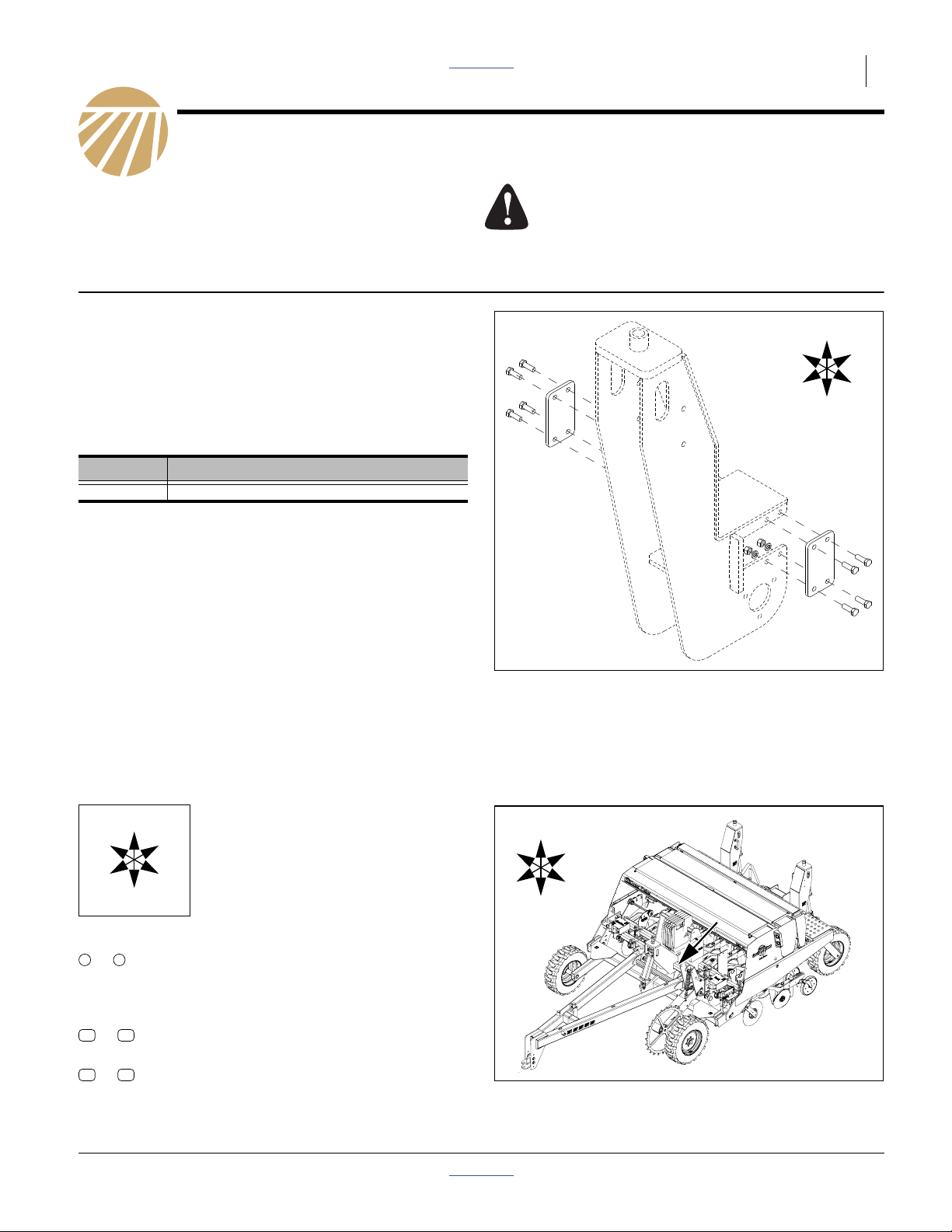
Figure 1
Kit Parts (Solid Lines)
L
B
U
F
R
D
29712
Notations and Conventions
U
F
L
D
Call-Outs
1 9
to
11
to
51 54
to
© Copyright 2009 Printed 08/21/2009 Part Lists 151-169M
Single-digit callouts identify components in
the currently referenced Figure. These numbers may be reused for different items from
page to page.
15
Two-digit callouts in the range 11 to 15 reference new parts from the list on page 7.
Two-digit callouts in the range 51 to 54 reference existing parts from the list on page 7
“Left” and “Right” are facing in the
direction of machine travel. An orienta-
R
tion rose in the line art illustrations
shows the directions of Left, Right,
Front, Back, Up, Down.
B
R
F
U
B
L
D
Figure 2
1007NT Serial Number Location
28454
2 Great Plains Manufacturing, Inc. Front Page Part Lists Caster Brace Update
Before You Start
Compatibility
Refer to Figure 2 on page 1
1. Verify from the serial number plate that the drill is the
model number (1007NT) compatible with this kit.
1. Check the gap where the caster weldments mount
on the frame cross-tube. Newer drills already have a
brace plate installed in gap and do not need this
kit.
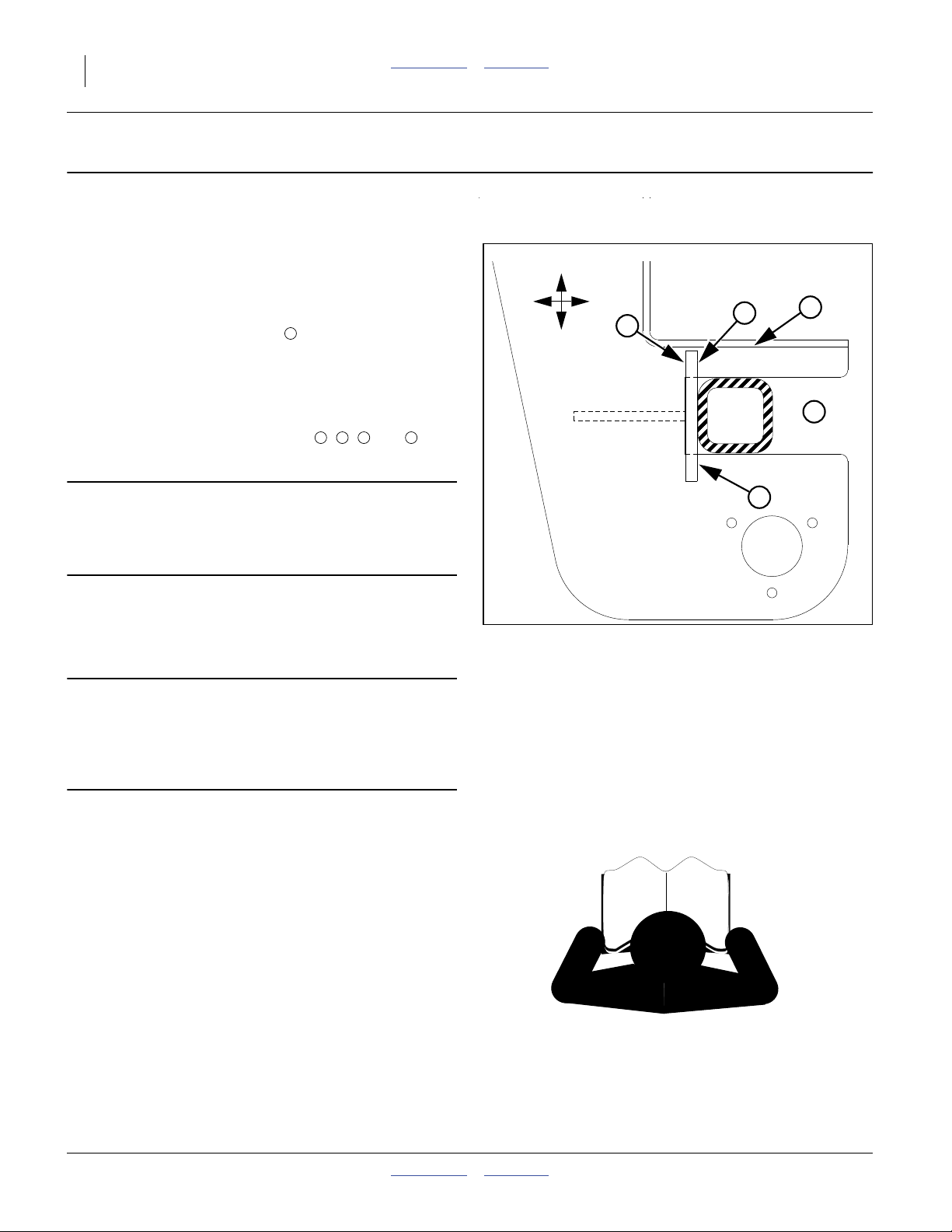
Refer to Figure 3
2. Clean the inside and outside surfaces of the general
installation area.
3. Inspect the weld fillets at points , , and , on
both sides of and inside the weldment.
1
2 3 4 5
B
U
D
F
3
2
4
1
IMPORTANT !
If any welds are cracked, do not install the kit.
Have your dealer contact Great Plains for further
assistance.
4. Inspect the general condition of the caster weldment
side plates. Perform a trial alignment of the brace
plate, as per step 15 through step 20 on page 5. Do
not mark the hole locations at this time.
IMPORTANT !
If the plate cannot lie flat against the weldment, or the
hole locations would not meet the center-line requirement of step 14, do not install the kit. Have your
dealer contact Great Plains for further assistance.
Inventory
5. Make sure all parts are present (page 7).
Comprehension
6. Review these instructions. Make sure the installers
understand where each part or assembly is installed,
and what tools are required for the task.
Note: Illustrations in this manual, based on the parts
manuals for this family of drills, may show
exploded views that are fully disassembled. Rely
on the instructions for required disassembly and
reassembly steps.
Figure 3
Inspect Caster Weldment
5
29713
151-169M Front Page Part Lists 08/21/2009

Pre-Assembly Preparation Front Page Part Lists Great Plains Manufacturing, Inc. 3
Pre-Assembly Preparation
Tools Required
• fire extinguisher (if grinding is required)
• Drill operator manual (see page 1)
• updated drill Parts Manual (see page 1)
• suitable tractor for raising implement
• basic hand tools, including:
center punch
drill
17
⁄
in (13.5mm) drill bit
32
3
⁄
in (5mm) pilot drill bit
16
• fine-tip marker
• touch-up paint may be required, Great Plains spray
can part number 821-001C, or use a green exterior
enamel close to Pantone® 356C.
Work Location
7. Move the implement to a location with:
• adequate illumination;
• clear surface beneath for recovery of any falling
or dropped parts - if the surface is not clear,
have a tarp or drop cloth available; and,
• no flammable materials near or beneath the drill.
Crushing Hazard
Do not loosen or remove the U-bolts that secure the caster
weldments to the frame tube. If raised, the drill may fall. If
lowered, the heavy caster weldments may topple.
Possible Fire Hazard
Fitting of the brace plates may require grinding, which will
produce sparks capable of starting a fire.
Prepare Implement
8. Raise the drill.
9. Install transport locks.
10. Lower parking jack and unhitch.
This installation may be performed with the drill lowered, but access to the site is less convenient.
The tractor may be left hitched if preferred.
08/21/2009 Front Page Part Lists 151-169M
 Loading...