

Great Plains 1007NT Operator Manual
Operator Manual
10-Foot No-Till Drill
Manufacturing, Inc.
www.greatplainsmfg.com
Read the operator’s manual entirely. When you see this symbol, the subsequent
instructions and warnings are serious - follow without exception. Your life and
!
the lives of others depend on it!
1007NT
28454
Illustrations may show optional equipment not supplied with standard unit.
© Copyright 2010 Printed 10/06/2010 150-290M

Blank

Great Plains Manufacturing, Inc. iii
Table of Contents
Important Safety Information............................ 1
Safety Decals ...............................................................5
Introduction ...................................................... 11
Description of Unit ......................................................11
Intended Usage ......................................................11
Models Covered .....................................................11
Document Family....................................................11
Using This Manual......................................................11
Definitions...............................................................11
Owner Assistance ......................................................12
Preparation and Setup..................................... 13
Initial Setup.................................................................13
Pre-Planting Setup .....................................................13
Pre-Setup Checklist................................................13
Hitching Tractor to Drill...........................................14
Either Hitch .........................................................14
Ball Hitch ............................................................14
Pintle Hitch .........................................................14
Safety Chain .......................................................14
Hydraulic Hose Hookup......................................15
Re-phasing Cylinders .........................................15
Electrical Connection..........................................16
Leveling the Drill .................................................16
Operating Instructions .................................... 17
Pre-Start Checklist .....................................................17
Drill Lift/Lower.............................................................18
Raising ...................................................................18
Raising for Transport, Parking or Storage ..........18
Raising after Transport, Parking or Storage .......18
Lowering.................................................................18
Caster Pivot Locks .....................................................19
Locking Casters......................................................19
Unlocking Casters ..................................................19
Transporting ...............................................................20
Transport on Drill Wheels.......................................20
Approximate 6in Configuration Weights .............20
Approximatea 7.5 Configuration Weights ...........20
For Any Transport...................................................21
Trailer Transport.....................................................21
Loading Trailer....................................................21
Unloading Trailer................................................ 21
Loading Materials....................................................... 22
Main Seed Box Loading ........................................ 22
Loading Native Grass Box ....................................22
Loading Small Seeds Box ..................................... 22
Loading Fertilizer.................................................... 22
Unused Boxes............................................................ 23
Ground Drive Lock-Up ...........................................23
Material Rates Overview............................................ 24
Seeding Depth Overview ........................................... 24
Acremeter Operation.................................................. 25
Normal Operating Sequence.................................. 25
Dormant Display................................................. 25
Field Operation .......................................................... 26
Parking....................................................................... 26
Storage ...................................................................... 26
Adjustments......................................................27
Seed and Fertilizer Rate ........................................27
Planting Depth........................................................ 27
Coulter Adjustments................................................... 28
Coulter Depth (All Rows)........................................ 29
Initial Setup ........................................................ 29
Fine Adjustment .................................................29
Front Eyebolt Adjustment....................................... 30
Coulter Down Pressure .......................................... 30
Available Coulter Force Per Row: 1007NT-157530
Available Coulter Force Per Row: 1007NT-190630
Coulter Spring Length ............................................ 31
Coulter Depth (Individual Rows) ............................32
Drill Weight Adjustment.............................................. 32
Calibration Overview.................................................. 33
Calibrate with Drill Raised ...................................... 33
Calibrate for
Calibration Crank Storage...................................... 33
Using Calibration Crank ......................................... 33
Row Unit Adjustments................................................ 34
Disc Blade Adjustments ......................................... 35
Adjusting Disc Contact ....................................... 35
Opener Adjustments .................................................. 36
Opener Down Pressure.......................................... 36
1
/10th Acre or Hectare....................... 33
© Copyright 2003, 2006, 2007, 2008, 2009, 2010. All rights Reserved.
Great Plains Manufacturing, Inc. providesthis publication “as is” without warranty of any kind, eitherexpressed or implied. While every precaution has been taken in the preparation
of this manual, Great Plains Manufacturing, Inc. assumes no responsibility for errors or omissions. Neither is any liability assumed for damages resulting from the use of the information contained herein. Great Plains Manufacturing, Inc. reserves the right to revise and improve its products as it sees fit. This publication describes the state of this product at
the time of its publication, and may not reflect the product in the future.
The following are trademarks of Great Plains Mfg., Inc.: Application Systems, Ausherman, Land Pride, Great Plains
All other brands and product names are trademarks or registered trademarks of their respective holders.
10/06/2010 150-290M
Great Plains Manufacturing, Incorporated Trademarks
Printed in the United States of America.

iv 1007NT Great Plains Manufacturing, Inc.
Disc Scraper Adjustment ....................................... 36
Seed-Lok™ Lock-Up.............................................. 37
Opener Depth (Press Wheel Height) .....................37
Troubleshooting ...............................................38
Maintenance and Lubrication..........................41
Maintenance .............................................................. 41
Materials Clean-Out ................................................... 42
Main Box Clean-Out............................................... 42
Native Grass Box Clean-Out.................................. 42
Small Seeds Box Clean-Out ..................................43
Fertilizer Box Clean-Out......................................... 43
Leveling Drill .............................................................. 44
Disc Maintenance .................................................. 45
Opener Disc Replacement ................................. 45
Coulter Disc Replacement ................................. 45
Chain Maintenance .................................................... 46
Chain Slack............................................................ 46
Seed Flap Replacement ............................................ 46
Lubrication ................................................................. 47
Options..............................................................52
Hitches ....................................................................... 52
Coulter Blades ........................................................... 52
Seed Box Agitator ...................................................... 53
Seed Tube Plug (Main Seeds)................................... 53
Series II Native Grass Attachment............................. 54
Seed Lubricants ..................................................... 54
Small Seeds Attachment............................................ 55
Seed Tube Plug (Small Seeds).............................. 55
Removable Partition............................................... 55
Fertilizer ..................................................................... 56
Carbide Disc Scraper................................................. 56
Seed Firmers ............................................................. 57
Seed-Lok® Seed Firmer ........................................ 57
Press Wheels............................................................. 57
Acremeter .................................................................. 57
Appendix A - Reference .................................. 58
Specifications and Capacities.................................... 58
Tire Inflation Chart ..................................................... 58
Torque Values ........................................................... 59
Hydraulic Diagram ..................................................... 60
Chain Routing............................................................ 61
Ground Drive Wheel to Jackshaft .......................... 61
Left Gearbox Input/Main Seed Box Drive .............. 62
Ground Drive to Accessory Jackshaft (Option)...... 63
Accessory Transmission (Option).......................... 64
Fertilizer Box Drive (Option) .................................. 67
Small Seeds Box Drive (Option) ............................ 68
Small Seeds Box Drive w/ Fertilizer (Option)......... 68
Native Grass Gearbox (Option) ............................. 69
Native Grass Jackshaft to Meters (Option)............ 70
Appendix B - Initial Setup ............................... 71
Installation Instructions .............................................. 71
Connector Identification ..................................... 71
Initial Setup................................................................ 72
Pre-Delivery Checklist ............................................... 72
Hydraulic Setup ......................................................... 73
Terminate Hoses ................................................... 73
Charge Hydraulic System ...................................... 73
Check Level ........................................................... 73
Set Hitch Height..................................................... 73
Install Options ........................................................ 73
Adjust Hitch Height .................................................... 74
Adjusting Either Hitch ............................................ 75
Adjusting Clevis Ball Hitch ..................................... 75
Adjusting Pintle Hitch............................................. 75
Reinstall Chain....................................................... 75
Scraper Installation.................................................... 76
Warranty .................................................................... 77
Index ................................................................. 79
150-290M 10/06/2010
Great Plains Manufacturing, Inc. 1
Important Safety Information
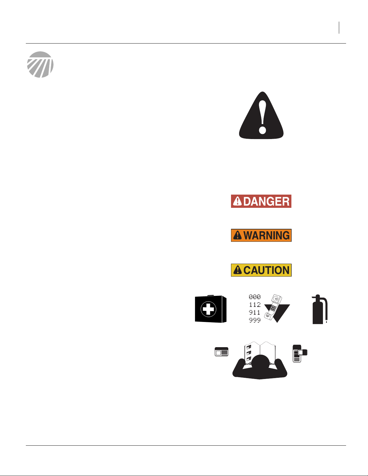
Look for Safety Symbol
The SAFETY ALERT SYMBOL indicates there is a
potential hazard to personal safety involved and extra
safety precaution must be taken. When you see this
symbol, be alert and carefully read the message that follows it. In addition to design and configuration of equipment, hazard control and accident prevention are
dependent upon the awareness, concern, prudence and
proper training of personnel involved in the operation,
transport, maintenance and storage of equipment.
Be Aware of Signal Words
Signal words designate a degree or level of hazard seriousness.
DANGER indicates an imminently hazardous situation
which, if not avoided, will result in death or serious injury.
This signal word is limited to the most extreme situations,
typically for machine components that, for functional purposes, cannot be guarded.
WARNING indicates a potentially hazardous situation
which, if not avoided, could result in death or serious
injury, and includes hazards that are exposed when
guards are removed. It may also be used to alert against
unsafe practices.
CAUTION indicates a potentially hazardous situation
which, if not avoided, may result in minor or moderate
injury. It may also be used to alert against unsafe practices.
Prepare for Emergencies
▲ Be prepared if a fire starts
▲ Keep a first aid kit and fire extinguisher handy.
▲ Keep emergency numbers for doctor, ambulance, hospital
and fire department near phone.
Be Familiar with Safety Decals
▲ Read and understand “Safety Decals” on page 5, thor-
oughly.
▲ Read all instructions noted on the decals.
▲ Keep decals clean. Replace damaged, faded and illegible
decals.
10/06/2010 150-290M
2 1007NT Great Plains Manufacturing, Inc.
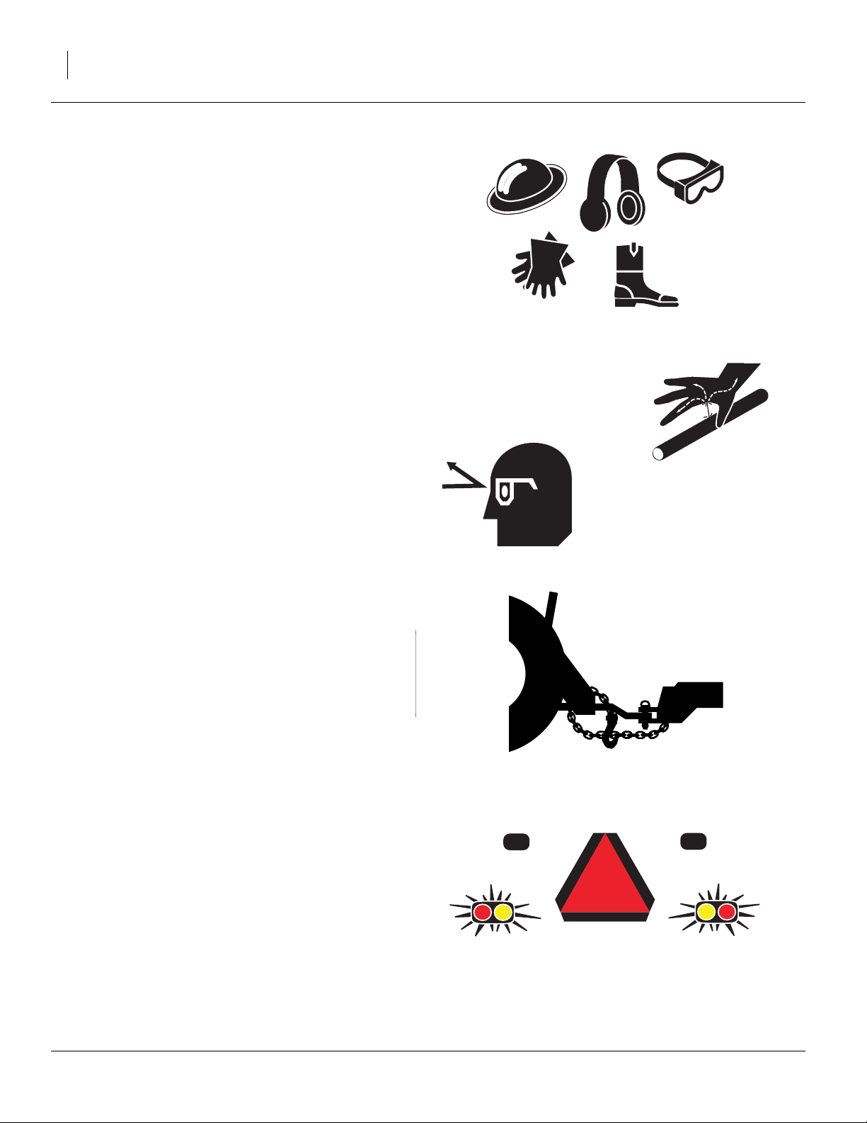
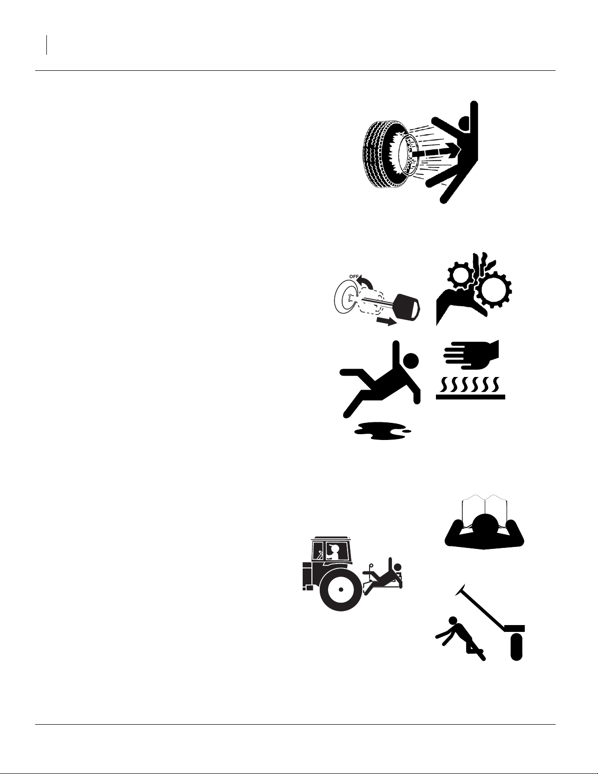
Wear Protective Equipment
▲ Wear protective clothing and equipment.
▲ Wear clothing and equipment appropriate for the job. Avoid
loose-fitting clothing.
▲ Because prolonged exposure to loud noise can cause hear-
ing impairment or hearing loss, wear suitable hearing protection such as earmuffs or earplugs.
▲ Because operating equipment safely requires your full
attention, avoid wearing entertainment headphones while
operating machinery.
Avoid High Pressure Fluids
Escaping fluid under pressure can penetrate the skin,
causing serious injury.
▲ Avoid the hazard by relieving pressure before disconnecting
hydraulic lines.
▲ Use a piece of paper or cardboard, NOT BODY PARTS, to
check for suspected leaks.
▲ Wear protective gloves and safety glasses or goggles when
working with hydraulic systems.
▲ If an accident occurs, seek immediate medical attention
from a physician familiar with this type of injury.
Use A Safety Chain
▲ Use a safety chain to help control drawn machinery should
it separate from tractor drawbar.
▲ Use a chain with a strength rating equal to or greater than
the gross weight of towed machinery.
▲ Attach chain to tractor drawbar support or other specified
anchor location. Allow only enough slack in chain to permit
turning.
▲ Replace chain if any links or end fittings are broken,
stretched or damaged.
▲ Do not use safety chain for towing.
Use Safety Lights and Devices
Slow-moving tractors and towed implements can create
a hazard when driven on public roads. They are difficult
to see, especially at night.
▲ Use flashing warning lights and turn signals whenever driv-
ing on public roads.
▲ Use lights and devices provided with implement
150-290M 10/06/2010
Great Plains Manufacturing, Inc. 3
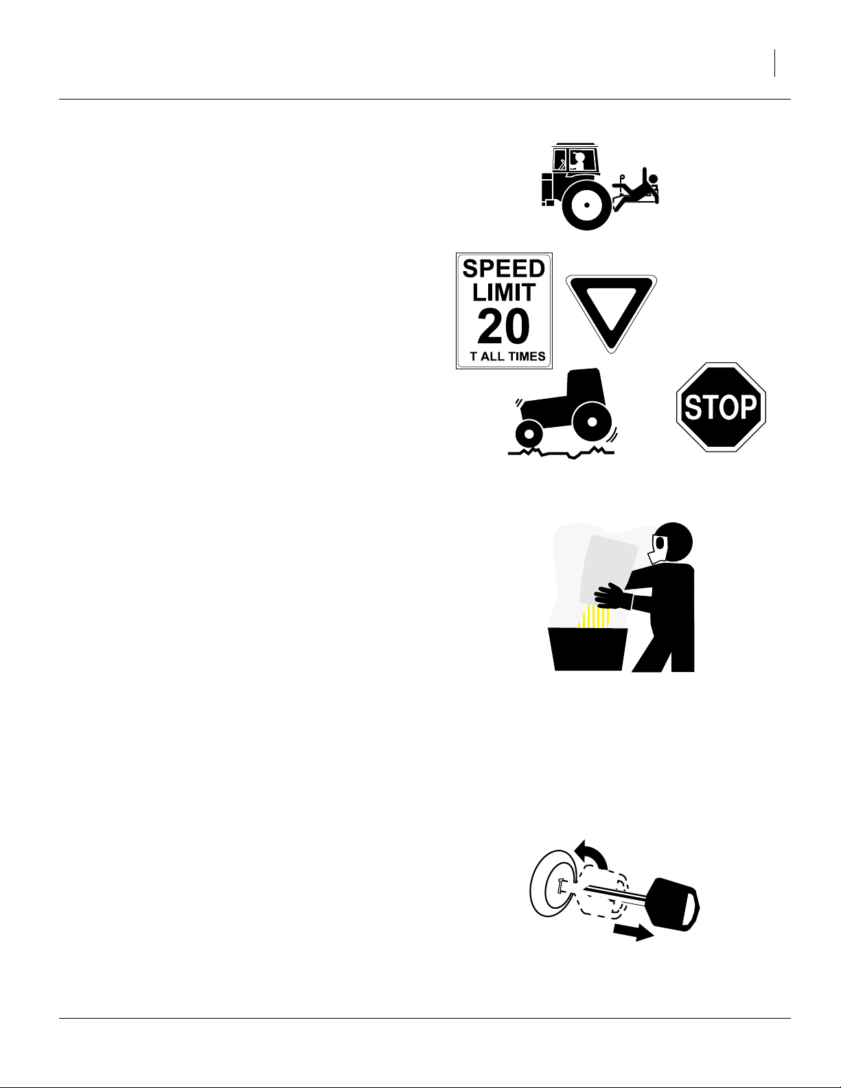
Keep Riders Off Machinery
Riders obstruct the operator’s view. Riders could be
struck by foreign objects or thrown from the machine.
▲ Never allow children to operate equipment.
▲ Keep all bystanders away from machine during operation.
Transport Machinery Safely
Maximum transport speed for implement is 20 mph (32
kph). Some rough terrains require a slower speed. Sudden braking can cause a towed load to swerve and
upset.
▲ Do not exceed 20 mph. Never travel at a speed which does
not allow adequate control of steering and stopping.
▲ Comply with state and local laws.
▲ Do not tow an implement that, when loaded for transport,
weighs more than 1.5 times the weight of towing vehicle.
▲ Carry reflectors or flags to mark drill in case of breakdown
on the road.
A
Handle Chemicals Properly
Agricultural chemicals can be dangerous. Improper use
can seriously injure persons, animals, plants, soil and
property.
▲ Do not use liquid treatments with drill.
▲ Read and follow chemical manufacturer’s instructions.
▲ Wear protective clothing.
▲ Handle all chemicals with care.
▲ Avoid inhaling smoke from any type of chemical fire.
▲ Never drain, rinse or wash dispensers within 100 feet (30m)
of a freshwater source, nor at a car wash.
▲ Store or dispose of unused chemicals as specified by chemi-
cal manufacturer.
▲ Dispose of empty chemical containers properly. Laws gen-
erally require power rinsing or rinsing three times, followed
by perforation of the container to prevent re-use.
Shutdown and Storage
▲ Lower drill, put tractor in park, turn off engine, and remove
the key.
OFF
▲ Secure drill using blocks.
▲ Detach and store drill in an area where children normally
do not play.
10/06/2010 150-290M
4 1007NT Great Plains Manufacturing, Inc.
Tire Safety
Tire changing can be dangerous and should be performed by trained personnel using correct tools and
equipment.
▲ When inflating tires, use a clip-on chuck and extension hose
long enough for you to stand to one side–not in front of or
over tire assembly. Use a safety cage if available.
▲ When removing and installing wheels, use wheel-handling
equipment adequate for weight involved.
Practice Safe Maintenance
▲ Understand procedure before doing work. Use proper tools
and equipment. Refer to this manual and your Parts Manual
for additional information.
▲ Work in a clean, dry area.
▲ Lower the drill, put tractor in park, turn off engine, and
remove key before performing maintenance.
▲ Make sure all moving parts have stopped and all system
pressure is relieved.
▲ Allow drill to cool completely.
▲ Disconnect battery ground cable (-) before servicing or
adjusting electrical systems or before welding on drill.
▲ Inspect all parts. Make sure parts are in good condition and
installed properly.
▲ Remove buildup of grease, oil or debris.
▲ Remove all tools and unused parts from drill before opera-
tion.
Safety At All Times
Thoroughly read and understand the instructions in this
manual before operation. Read all instructions noted on
the safety decals.
▲ Be familiar with all drill functions.
▲ Operate machinery from the driver’s seat only.
▲ Do not leave drill unattended with tractor engine running.
▲ Do not dismount a moving tractor. Dismounting a moving
tractor could cause serious injury or death.
▲ Do not stand between the tractor and drill during hitching.
▲ Keep hands, feet and clothing away from power-driven
parts.
▲ Wear snug-fitting clothing to avoid entanglement with mov-
ing parts.
150-290M 10/06/2010
Great Plains Manufacturing, Inc. 5
Safety Decals
Your implement comes equipped with all lights, safety
reflectors and decals in place. They were designed to
help you safely operate your implement.
▲ Read and follow decal directions.
▲ Keep lights in operating condition.
▲ Keep all safety decals clean and legible.
▲ Replace all damaged or missing decals. Order new decals
from your Great Plains dealer. Refer to this section for
proper decal placement.
▲ When ordering new parts or components, also request cor-
responding safety decals.
To install new decals:
1. Clean the area on which the decal is to be placed.
2. Peel backing from decal. Press firmly on surface,
being careful not to cause air bubbles under decal.
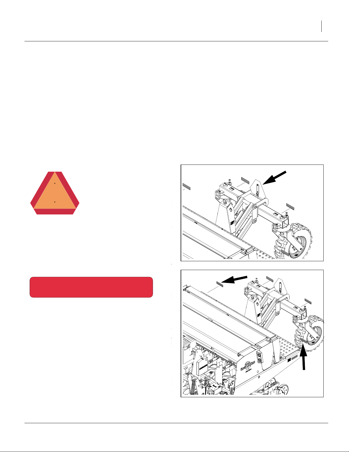
818-055C
Slow Moving Vehicle Reflector
On back of walkboard, center;
one total
838-266C
Red Reflectors
Rear face, outside ends of walkboard;
two total
31606
31606
10/06/2010 150-290M
6 1007NT Great Plains Manufacturing, Inc.
838-265C
Amber Reflectors
Outside ends walkboard,
front face of frame, outside corners,
four total
31606
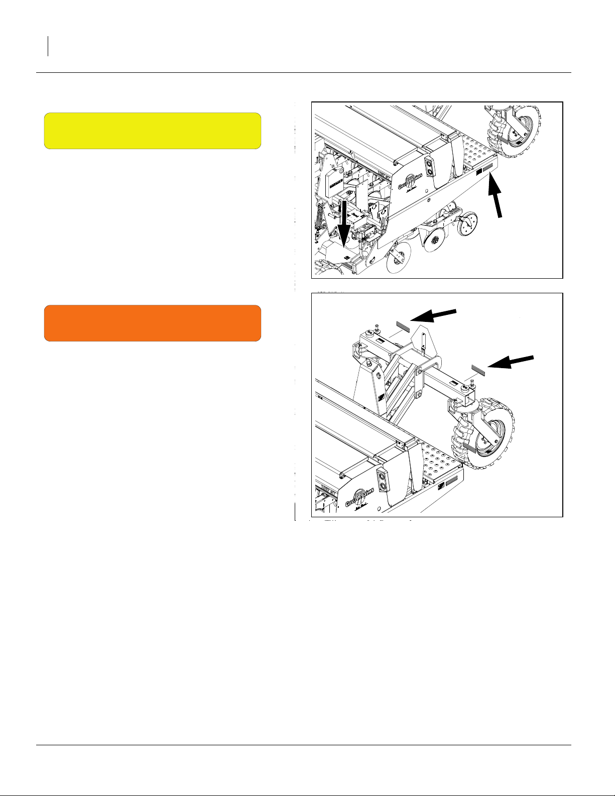
838-267C
Daytime Reflectors
Rear face walkboard, inboard of red reflectors;
two total
31606
150-290M 10/06/2010
Great Plains Manufacturing, Inc. 7
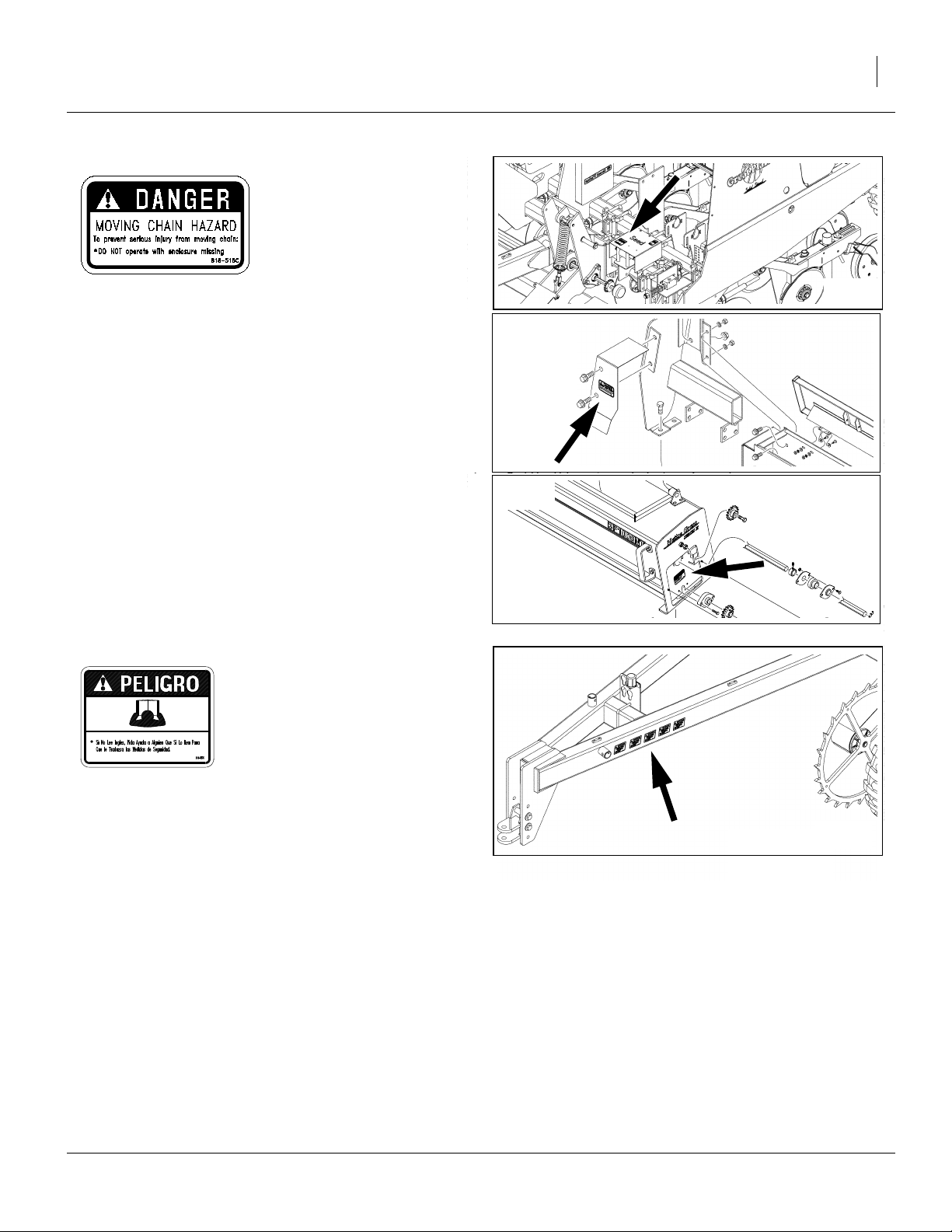
818-518C (Option)
Danger: Moving Chain
On each gearbox cover,
on Small Seeds chain guard,
under cover plate at final Native Grass sprocket;
1 to 4 total
818-557C
28457
28098
28221
Danger: Cannot Read English
On tongue at hitch;
1 total
10/06/2010 150-290M
28457
8 1007NT Great Plains Manufacturing, Inc.
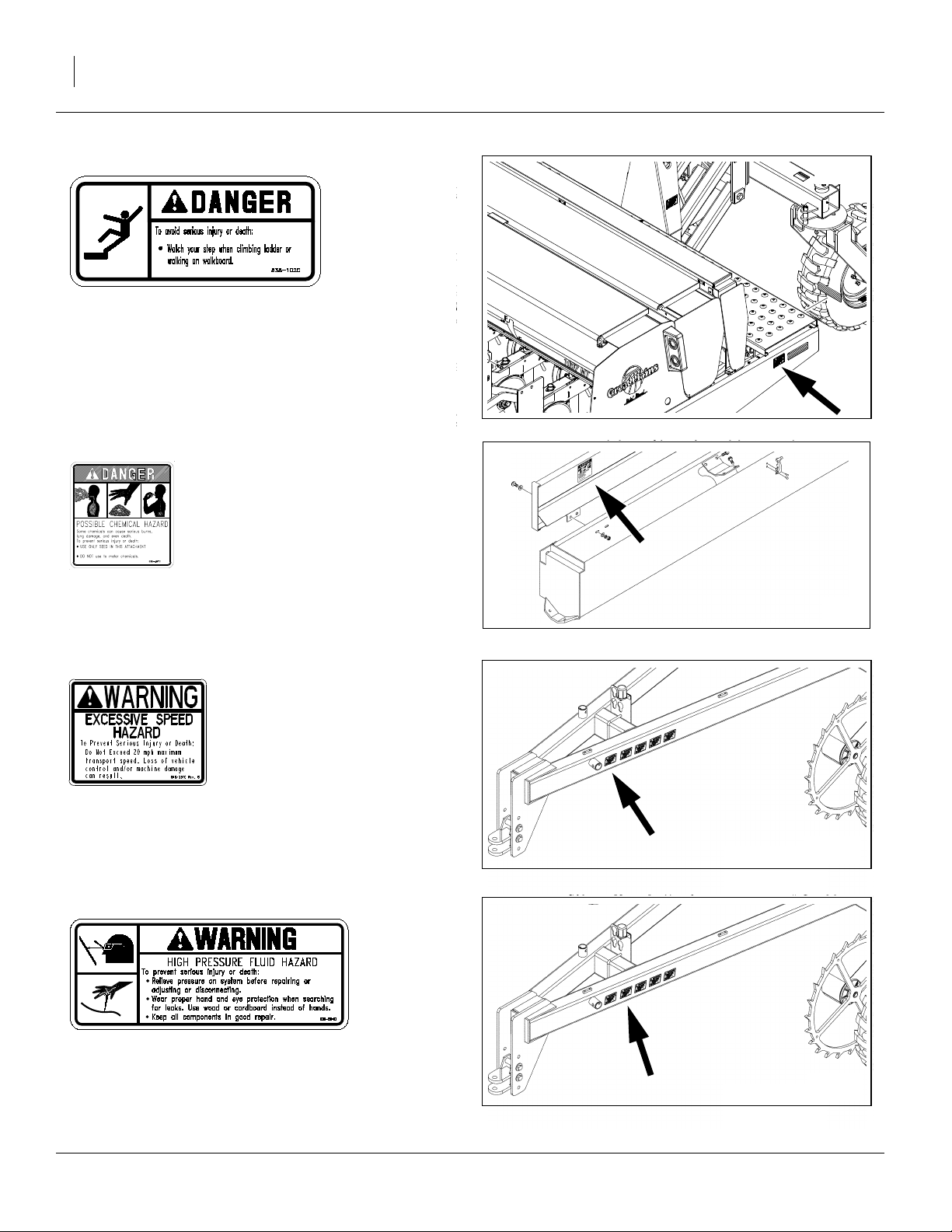
838-102C
Danger: Falling Hazard
on face of walkboard near ladder top;
one total
838-467C (Option)
Danger: Possible Chemical Hazard
inside lid of optional Small Seeds box;
one total
31606
21730
818-337C
Warning: Excessive Speed Hazard
On tongue at hitch;
1 total
818-437C
Warning: High Pressure Fluid Hazard
on tongue near hitch;
one total
28457
28457
150-290M 10/06/2010
Great Plains Manufacturing, Inc. 9
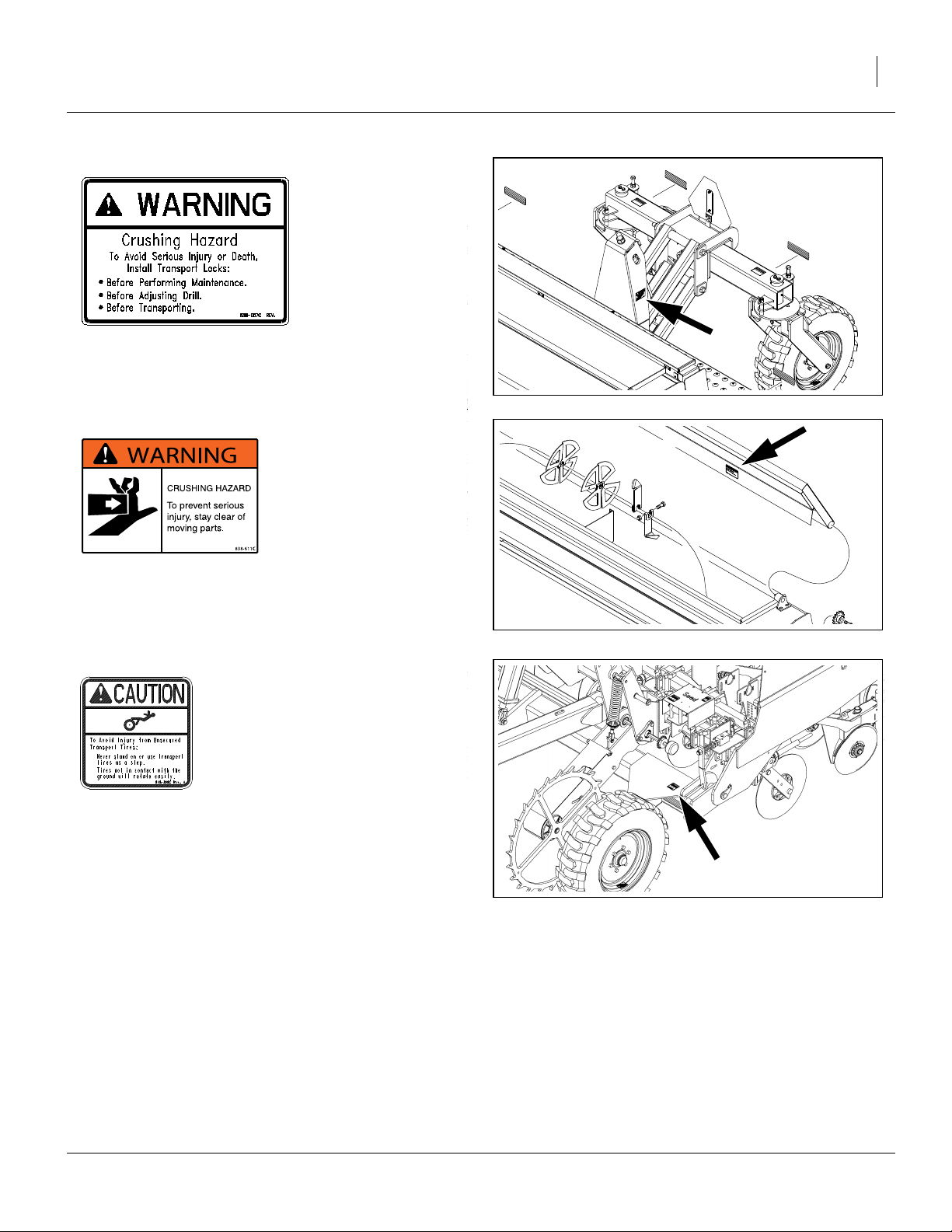
838-057C
Warning: Crushing Hazard
side face of lift assist weldment;
two total
838-611C (Option)
Warning: Hand Crushing Hazard
inside lid, Native Grass seed box;
one total
31606
28221
818-398C
Caution: Tires Not a Step
top face, front gauge wheel weldments;
two total
28457
10/06/2010 150-290M
10 1007NT Great Plains Manufacturing, Inc.
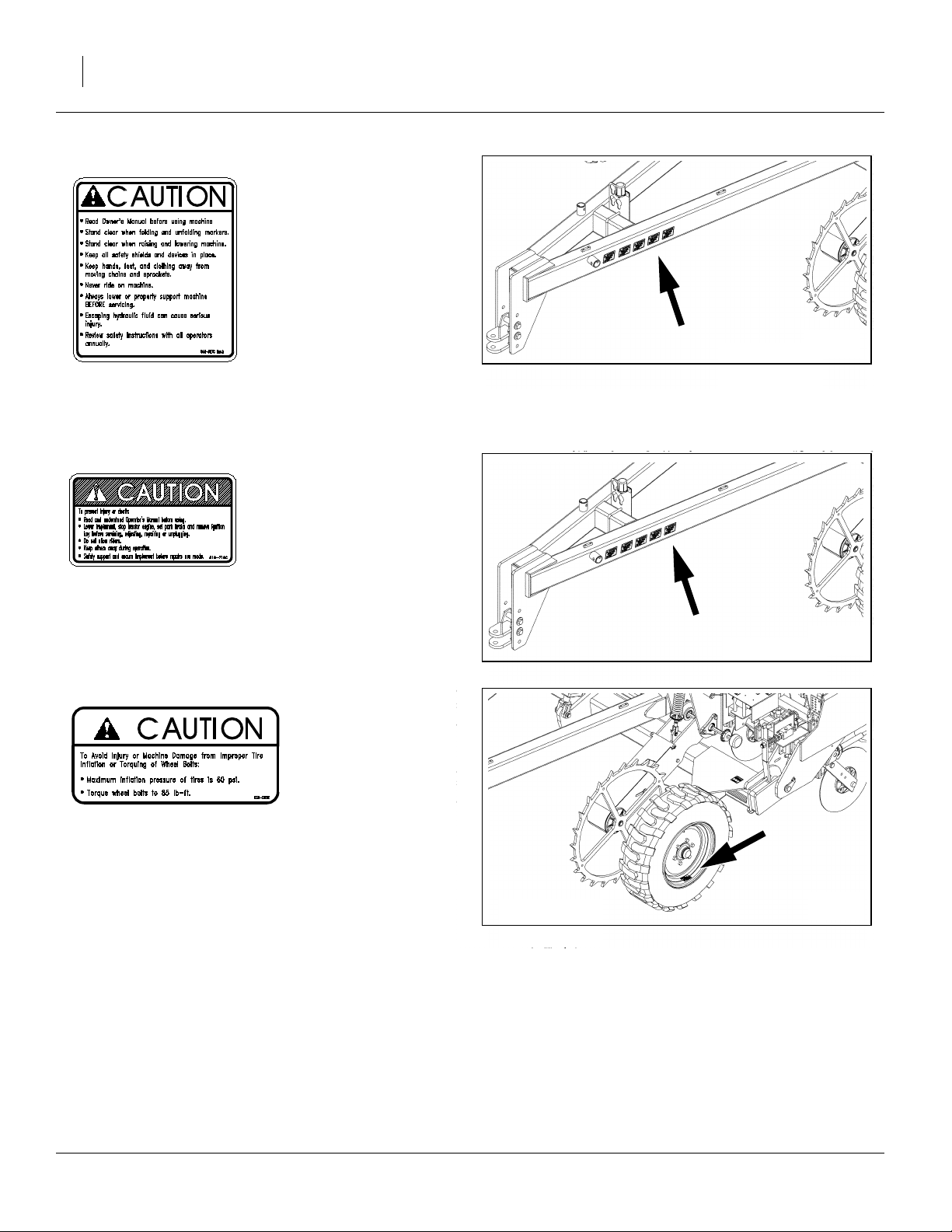
818-587C
28457
Caution: General Instructions
front face, top front tool bar, near center;
one total
818-719C
Caution: General Instructions
front face, top front tool bar, near center;
one total
838-092C
Caution: Tire Inflation
for 265/70B16.5 Skid Steer tires only
outside face of each wheel tire rim;
four total
End of Decals
28457
28457
150-290M 10/06/2010
Great Plains Manufacturing, Inc. Introduction 11
Introduction
Great Plains welcomes you to its growing family of new
product owners. This drill has been designed with care
and built by skilled workers using quality materials.
Proper setup, maintenance and safe operating practices
will help you get years of satisfactory use from the
machine.
Description of Unit
The 1007NT is a 10 foot pull-type seeding implement
designed for no-till conditions. It is equipped with hydraulic depth control and rear lift-assist. Coulters mounted on
the drill frame cut channels for the opener discs. The
opener discs clear away crop residue and open a seed
trench. Seed tubes between the opener discs place seed
in the trench, and press wheels firm soil over the seed.
The press wheels also gauge opener depth.
R
Intended Usage
Use this drill to seed grasses or production-agriculture
crops or to seed over existing grass stands, in ground
conditions that are flat to semi-flat or gently rolling.
Models Covered
1007NT-1575 15 Row, 7.5in (19.1cm) Row Spacing
1007NT-1906 19 Row, 6.0in (15.2cm) Row Spacing
Document Family
150-290M Operator manual (this manual)
150-290B Seed Rate manual
150-290P Parts manual
Using This Manual
This manual will familiarize you with safety, assembly,
operation, adjustments, troubleshooting and maintenance. Read this manual and follow the recommendations to help ensure safe and efficient operation.
The information in this manual is current at printing.
Some parts may change to assure top performance.
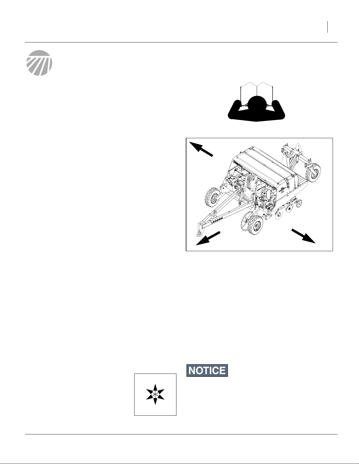
Definitions
The following terms are used throughout this manual.
Right-hand and left-hand as used in
this manual are determined by facing
the direction the machine will travel
while in use unless otherwise stated.
An orientation rose in some line art
illustrations shows the directions of:
Up, Back, Left, Down, Front, Right.
U
R
F
D
B
L
L
Figure 1
Model 1007NT
A crucial point of information related to the preceding topic.
For safe and correct operation, read and follow the directions
provided before continuing.
Note: Useful information related to the preceding topic.
28454
10/06/2010 150-290M

12 1007NT Great Plains Manufacturing, Inc.
Owner Assistance
If you need customer service or repair parts, contact a
Great Plains dealer. They have trained personnel, repair
parts and equipment specially designed for Great Plains
products.
Your machine’s parts were specially designed and
should only be replaced with Great Plains parts. Always
use the serial and model number when ordering parts
from your Great Plains dealer.
Refer to Figure 2
The serial-number plate is located on the front face of the
frame.
Record your drill model and serial number here for quick
reference:
Model Number:________________________________
Serial Number: ________________________________
Your Great Plains dealer wants you to be satisfied with
your new machine. If you do not understand any part of
this manual or are not satisfied with the service received,
please take the following actions.
1. Discuss the matter with your dealership service
manager. Make sure they are aware of any problems
so they can assist you.
2. If you are still unsatisfied, seek out the owner or general manager of the dealership.
3. For further assistance write to:
Figure 2
Serial Number Plate
28454
Product Support
Great Plains Mfg. Inc., Service Department
PO Box 5060
Salina, KS 67402-5060
785-823-3276
150-290M 10/06/2010

Great Plains Manufacturing, Inc. Preparation and Setup 13
Preparation and Setup
This section helps you prepare your tractor and drill for
use.
Initial Setup
If the drill has just been delivered, or broken down for reshipment, these items need to be completed prior to first
field use:
•“Initial Setup” on page 72, which includes:
•“Hydraulic Setup” on page 73, and
•“Adjust Hitch Height” on page 74
You may also need to install features, options and accessories that are not factory-installed, including:
•“Seed Rate Reduction Installation”
(separate manual),
•“Scraper Installation” on page 76.
Pre-Planting Setup
The balance of this section covers items that need to be
completed or checked prior to each field use of the drill.
Pre-Setup Checklist
1. Read and understand “Important Safety Informa-
tion” on page 1.
2. Check that all working parts are moving freely, bolts
are tight, and cotter pins are spread.
3. Check that all grease fittings are in place and lubri-
cated. Refer to “Lubrication” on page 47.
4. Check that all safety decals and reflectors are cor-
rectly located and legible. Replace if damaged. See
“Safety Decals” on page 5.
5. Inflate tires to pressure recommended and tighten
wheel bolts as specified. See “Torque Values” on
page 59.
10/06/2010 150-290M
14 1007NT Great Plains Manufacturing, Inc.
d
f
r
Hitching Tractor to Drill
In lowered (field) position, with the drill frame set at the
desired height via depth control valve (see page 29), the
tongue must be level.
When hitching for the first time:
• it is necessary to adjust hitch height (page 74), and
• it may be necessary to change the position of the clevis or pintle hitch in the tongue weldment (page 75).
Either Hitch
1. Back tractor close to hitch, and use parking jack to
match heights between tractor hitch/drawbar and drill
hitch.
2. For pintle hitch, skip to step 7.
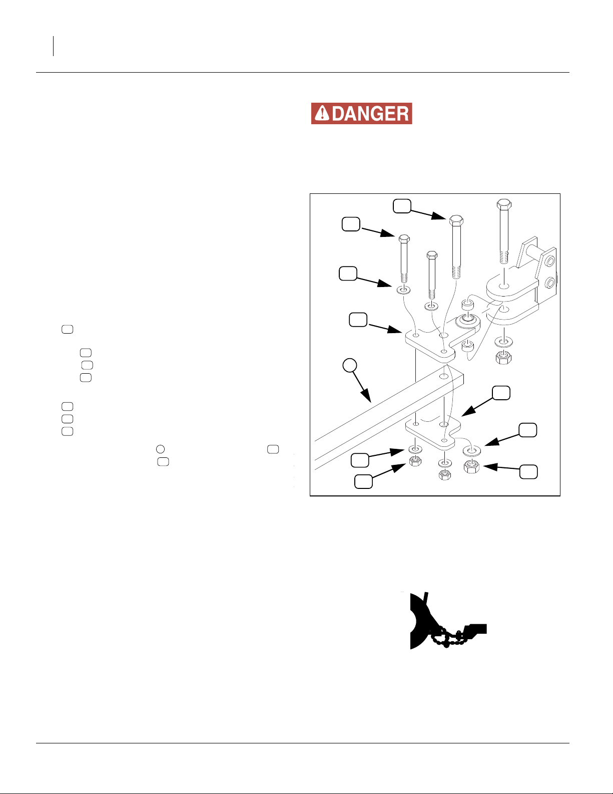
Ball Hitch
Refer to Figure 3
3. Remove hitch bottom plate:
14
177-589D BALL SWIVEL MOUNT BOTTOM PLATE
by removing:
22
two 803-148C NUT HEX NYLOCK 5/8-11 PLT
25
four 804-019C WASHER FLAT 5/8 USS PLT
16
two 802-060C HHCS 5/8-11X4 GR5
4. Remove hitch bolt:
18
802-098C HHCS 1-8X4 1/2 GR5
28
804-028C WASHER FLAT 1 USS PLT
21
803-038C NUT HEX 1-8 NYLON INSERT PLT
You may be severely injured or killed by being crushe
between the tractor and drill. Do not stand or place any part o
your body between drill and moving tractor. Stop tracto
engine and set park brake before installing hitch pin or assembling hitch plates to drawbar.
18
16
25
12
1
14
28
5. Back tractor drawbar under swivel top plate .
Position bottom plate under drawbar, and secure
with bolts, washers and nuts.
6. Skip to step 10.
Pintle Hitch
7. Use the jack stand crank to raise the hitch strap
slightly. Back the tractor so that its drawbar is aligned
with the strap hole.
8. Shut off the tractor and set the parking brake.
9. Insert and secure the hitch pin.
Safety Chain
10. Connect the safety chain around a suitable anchor
location on the tractor. Take up enough chain slack
so that no part of the chain touches the ground.
11. Retract foot of jackstand. Un-pin stand, remove and
re-pin on storage stob on top of tongue.
112
14
25
22
Figure 3
Ball Hitch
21
28117
150-290M 10/06/2010
Great Plains Manufacturing, Inc. Preparation and Setup 15
Hydraulic Hose Hookup
Connect hydraulic system to tractor before lifting the drill.
Escaping fluid under pressure can have sufficient pressure to
penetrate the skin. Check all hydraulic lines and fittings before
applying pressure. Fluid escaping from a very small hole can
be almost invisible. Use paper or cardboard, not body parts,
and wear heavy gloves to check for suspected leaks. If injured,
seek immediate medical attention from a physician familiar
with this type of injury.
The hydraulic system of the 1007NT drill has one circuit,
which controls two functions:
• Forward lift with depth-control stop valve.
• Rear lift-assist, which is fully retracted in the field.
Note: Prior to first use, adapt the
1
tings to connectors compatible with the tractor.
Use liquid pipe thread sealant (not tape) on NPT.
A poppet style QD(Quick Disconnect) to
1
⁄
in male NPT hose fit-
2
1
⁄
in FNPT
2
1
coupler is available as Great Plains part 811-856C.
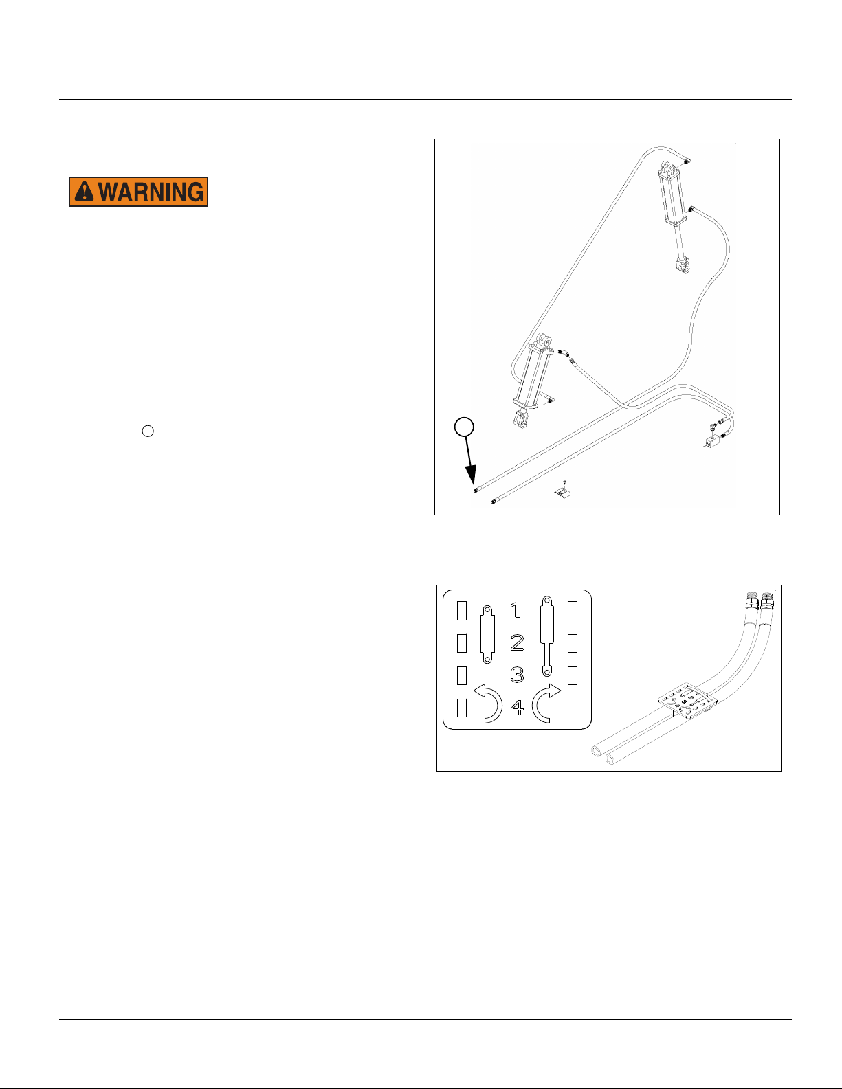
Refer to Figure 4
To distinguish hoses on the same hydraulic circuit, refer
to plastic hose label. The hose under an extended-cylinder symbol feeds a cylinder base end. The hose under a
retracted-cylinder symbol feeds a cylinder rod end.
12. Connect the hydraulic hoses to the tractor remotes.
Re-phasing Cylinders
The lift cylinders may, after a period of time, get out of
time or phase. The effects of this can be seen when not
all cylinders are fully extended at full lift.
To re-phase the cylinders, raise drill completely and hold
tractor hydraulic lever on for a few seconds to give cylinders time to re-phase.
Each time drill is raised out of ground momentarily
reverse hydraulic lever immediately after re-phasing to
allow cylinders to retract about
1
⁄
in (13mm). This helps
2
in maintaining a level drill.
Note: Having cylinders become gradually out of time is
different than air trapped in the system. Each condition is corrected differently. Perform “Hydraulic
Setup” on page 73 to purge air from the system.
Figure 4
Drill Hydraulic System
Figure 5
Plastic Hose Label
31608
817-348c
17641
10/06/2010 150-290M
16 1007NT Great Plains Manufacturing, Inc.
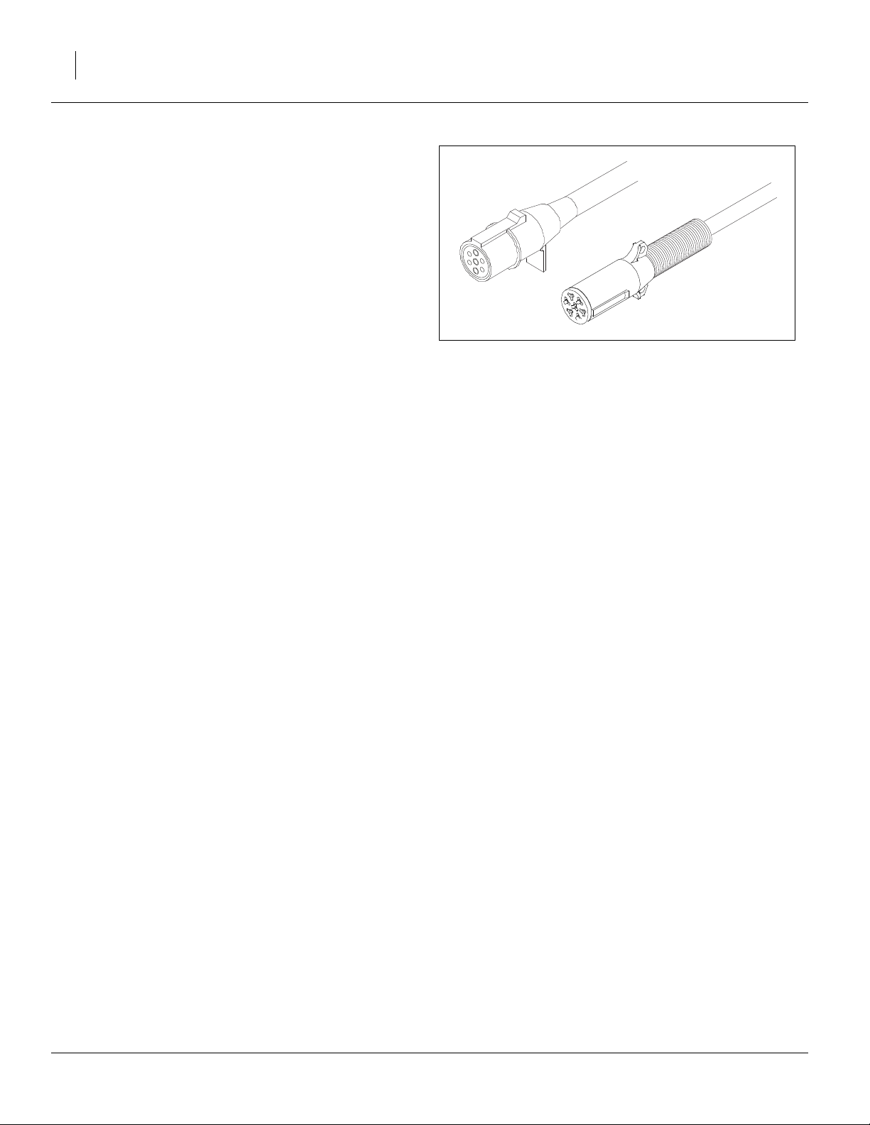
Electrical Connection
Refer to Figure 6
(which depicts both European and North American style connectors - if your implement does not have the correct
connector for your tractor, contact your Great Plains dealer)
13. Plug the drill lighting connector into tractor outlet.
14. Coil-up and tie-up excess cable, allowing enough
slack for turns and ridges.
Leveling the Drill
Before making depth control adjustments (page 29):
• the hydraulic system must be free of air (page 73),
• the cylinders must be re-phased (page 15), and;
Figure 6
Lighting Connectors
27172
26467
• the drill must be level front to back and side to side.
Drill level needs to be checked prior to first use, and periodically thereafter. See “Leveling Drill” on page 44.
150-290M 10/06/2010

Great Plains Manufacturing, Inc. Operating Instructions 17
Operating Instructions
This section covers general operating procedures. Experience, machine familiarity and the following information
will lead to efficient operation and good working habits.
Always operate farm machinery with safety in mind.
Pre-Start Checklist
Escaping fluid under pressure can have sufficient pressure to
penetrate the skin. Check all hydraulic lines and fittings before
applying pressure. Fluid escaping from a very small hole can
be almost invisible. Use paper or cardboard, not body parts,
and wear heavy gloves to check for suspected leaks. If injured,
seek immediate medical attention from a physician familiar
with this type of injury.
1. Carefully read “Important Safety Information” on
page 1.
2. Lubricate drill as indicated under “Lubrication” on
page 47.
3. Check all tires for proper inflation. See
Chart
” on page 58.
4. Check all bolts, pins and fasteners. Torque as shown
in “Torque Values” on page 59.
5. Check drill for worn or damaged parts. Repair or
replace parts before going to the field.
6. Check hydraulic hoses, fittings and cylinders for
leaks. Repair or replace before going to the field.
7. Rotate each ground drive wheel to see that the
drives and meters are working properly and free
from foreign material.
“Tire Inflation
Watch your step when walking on drill ladder and walkboard.
Falling from drill could cause severe injury or death.
10/06/2010 150-290M
18 1007NT Great Plains Manufacturing, Inc.
Drill Lift/Lower
Raising and lowering the drill relies on one front cylinder,
and one rear lift-assist cylinder. Both cylinders are on the
same circuit and operate in unison, although at different
rates front to back.
When lowered, the rear lift-assist arms raise more rapidly
than the front rockshaft, resulting in the rear caster
wheels being off the ground during planting. The rear
wheels play no role in setting planting depth.
Lowered position is set by a depth control valve, which
stops oil flow to the cylinders at a height you determine.
Raised position is normally fully raised, then lowered
onto lock channels for transport.
Raising
1. Activate the lift circuit lever to Extend the lift cylinders
fully. Set circuit to Neutral.
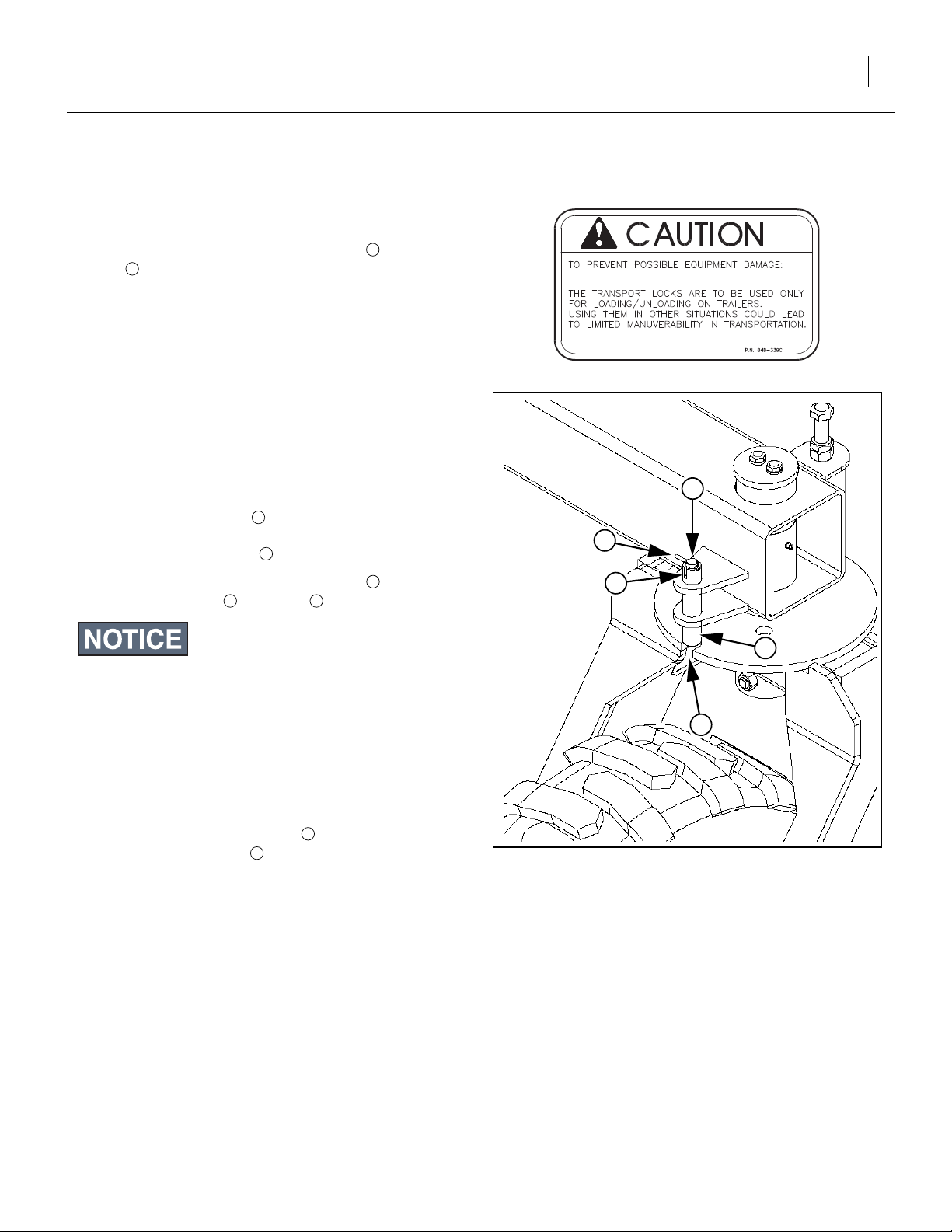
Raising for Transport, Parking or Storage
Refer to Figure 7 and Figure 8
3. Set tractor parking brake and shut off tractor.
4. Rotate the lock channel at the front cylinder until
the polymer bumpers snap around the rod. Place
lock channel on lift-assist cylinder.
Note: If any cylinder is not sufficiently extended to permit
lock channel engagement, system needs to be rephased (page 15)
5. Slowly move lift circuit lever to Float, allowing cylinders to settle on lock channels.
6. Set circuit to Neutral to transport.
Leave circuit in Float for parking, storage or maintenance.
Raising after Transport, Parking or Storage
7. Extend circuit for lift cylinders, until cylinders clear
lock channels. Set circuit to Neutral.
8. Swing front lock channel away from cylinder rod and
remove lift-assist lock channel from rear cylinder rod.
9. Store lift-assist lock channel on side of mount .
Secure pin in hole provided.
2
1
3
Lowering
If lowering from transport, parking or storage, it is first
necessary to raise the drill, and disengage the lock channels.
10. Move the tractor remote circuit lever to Retract.
Normally, drill lowers until openers contact the ground,
rear lift assist wheels rise off ground, and rockshaft continues to lower until depth control stop halts front lift cylinder retraction.
11. Move lift circuit lever to Neutral.
See page 29 for depth control stop valve adjustments.
Crushing Hazard - Rely on circuit Neutral to hold the drill
raised only for field turns. Use lock channels for all other
raised operations: transport, parking, maintenance and storage.
1
Figure 7
Front Lock Channel
2
Figure 8
Lift-Assist Lock Channel
28464
3
31610
150-290M 10/06/2010
Great Plains Manufacturing, Inc. Operating Instructions 19
Caster Pivot Locks
Refer to Figure 9
To prevent side movement of the drill when transported
by trailer, the lift-assist casters may be locked in their full-
reversing orientation. A spring-loaded pin engages a
cutout in the caster pivot plate, preventing rotation.
Use this feature only for trailer transport. Do not use
these locks for towing drill on own wheels or field operations.
2
Locking Casters
Refer to Figure 9 and Figures 7 and 8 on page 18
1. With drill hitched, raise drill (page 18). Install lift lock
channels.
2. Begin backing drill toward trailer until casters swing
into reverse and drill is aligned with trailer. Stop a
short distance from the trailer.
3. Lift locking cross-pin out of upper (disengagement) detents. Rotate cross-pin and release into
deeper locking detent
3
4
1
1
3
4. Continue backing drill until lock tubes are aligned
with plate cutout , and pins engage cutouts.
Do not continue onto trailer unless both lock pins are engaged.
2 1
5
Unlocking Casters
1. Hitch drill before unlocking.
2. Leave the lock pins in place until the drill is removed
from the trailer, unless the trailer bed has more than
ample width to permit casters to safely make a full
turn.
3. At each caster, lift cross-pin out of lower (lock
engagement) detent . Rotate cross-pin and
release into upper (disengagement) detent.
4
3
4
2
Figure 9
Caster Pivot Unlocked
5
31611
10/06/2010 150-290M

20 1007NT Great Plains Manufacturing, Inc.
Transporting
The drill may be transported on its own wheels, or on a
trailer.
Transport on Drill Wheels
Before transporting with a tractor, check these items:
1. Check that tractor is sufficient for towing the drill.
Tractor must have at least 80 horsepower (60 kW).
Use a tractor with adequate weight relative to drill.
See the tables below for typical drill weights.
2. Unload drill boxes. The drill can be transported with
full boxes of material (other than native Grass), but
the added weight increases stopping distance and
decreases maneuverability. Unload before transporting if possible.
3. Raise drill completely (page 18).
4. Install lock channels on lift cylinders (page 18).
Note: The cylinder locks can be secured or removed only
with drill fully raised.
Approximatea 6in Configuration Weights
Unstable Load Hazard: Tow the drill only with a tractor with
sufficient power and that weighs at least 2/3 (67%) of the drill.
An implement that weighs more than 150% of the towing vehicle is a dangerously unstable load in braking and turning.
Excessive Speed Hazard: Towing the drill at high speeds can
lead to loss of vehicle control and a serious road accident,
injury and death. To reduce the hazard, do not exceed 20 mph.
Failure of hydraulic cylinders or tractor circuit during transport will cause drill to drop suddenly, which could lead to serious road accidents, injury or death. To prevent an accident,
always install cylinder lock channels before transporting drill.
Do not transport with Native Grass box loaded. Heavier mix
components settle to the bottom, which can prevent drive system from operating or cause irregular seed rate and population distribution.
Approximatea 7.5 Configuration Weights
a. Weights are approximate, and can vary by hundreds of pounds based on material density, press wheel options, accessories and user
modifications. Additional “Weights” figures presume 10 each 100 pound suitcase weights.
150-290M 10/06/2010

Great Plains Manufacturing, Inc. Operating Instructions 21
For Any Transport
Keep Clearance in Mind
Remember that the drill may be wider than the tractor.
Allow safe clearance.
Observe Road Rules
Comply with all national, regional and local safety laws
when traveling on public roads.
Trailer Transport
Loading Trailer
1. Hitch raised and locked drill to suitable tractor.
2. Carefully line-up the tractor, drill and trailer, so that:
a. no turns are needed for the final movement, and
b. the casters are fully reversed.
3. Lower caster swivel lock pins to lock position
(page 19).
4. Carefully back the drill onto the trailer bed.
Unstable Load Hazard: Do not transport on a trailer of insufficient width or length. Unless all transport tires are on the
bed, too few openers are supporting the entire drill. The load
may spill, with risk of serious injury or death to anyone
nearby, and certainty of major equipment damage.
5. Remove transport locks and lower the drill (page 18).
6. Unhitch the tractor.
7. Secure the load with cargo straps or chains.
Unloading Trailer
1. Release cargo straps or chains.
2. Hitch suitable tractor with available hydraulic remote
(page 14).
3. Confirm that caster pivot swivel locks are still in place
(page 19).
4. Raise drill (page 18).
5. Install lift-assist cylinder transport locks (page 18).
6. Carefully tow drill from trailer.
7. Remove caster pivot swivel locks.
Load Maneuvering Hazard - Use care and planning when
loading or unloading the drill in trailer transport. The rear
casters may turn and force the drill off the trailer.
▲ Make sure the trailer is rated for the load.
▲ Make sure the trailer is wide enough for the load.
▲ Make sure the load is secured properly.
10/06/2010 150-290M
22 1007NT Great Plains Manufacturing, Inc.
Loading Materials
Fully loaded with dense seed and fertilizer, the drill
weighs an additional 1970 lbs (894 kg). Include this
weight when checking tractor capability.
The drill must be hitched for seed loading.
Load slightly more material than needed, because consumption rates can vary between compartments even
though the furrow rates are identical.
1
Main Seed Box Loading
1. Check that all meter doors are positioned for the
seed size, and not set for clean-out. See “Position
Seed Cup Doors” in seed Rate Manual. If loading
prior to transport, set them to position 1 (smallest
seed).
2. Install or remove optional seed plugs as desired for
the row spacing planned. See “Seed Tube Plug
(Small Seeds)” on page 55.
If loading prior to transport, and calibration has not yet
been done, set Seed Rate Handle to 0. At 0, and with the
doors at 1, no seed can leak during transport.
3. The main seed box lid handle is also a latch. It needs
to pivot up to release the lid.
4. Load seed evenly into compartments.
To reduce wear on unused boxes that may also be
present:
• Remove final drive chain for small seed box.
• Remove ground drive chain in Native Grass (right
wheel).
Take all prescribed material
safety precautions.
23
Figure 10
Native Grass Box Open
1
28362
2
Loading Native Grass Box
1. The main seed box lid handle is also a latch. It needs
to pivot up to release the lid.
2. Load seed evenly into compartments.
3
Loading Small Seeds Box
1. If loading prior to transport, and calibration has not
yet been done, set Seed Rate Handle to 0. At 0, no
seed can leak during transport.
2. Take all necessary materials safety precautions if the
seed is treated.
3. The Small Seeds lid is held closed by two external
rubber latches. Pull them up and to the rear to
release the lid.
4. Load seed evenly into compartments.
5. To reduce wear, remove main shaft drive chains for
main seed boxes.
150-290M 10/06/2010
Loading Fertilizer
Fully loaded with dense fertilizer, the drill can weigh an
additional 700 lbs (318 kg) or more. Include this weight
when checking tractor capability.
Load fertilizer after transport if possible. Some spillage
can occur through meters during transport, even with the
drive system disengaged.
1. Check that fertilizer clean-out door is closed and all
latches are secure.
2. If loading prior to transport, and calibration has not
yet been done, set Rate Adjuster to 0. At 0, no fertilizer can leak during transport.
3. The fertilizer lid is held closed by a spring-loaded
bumper. Lift smartly at the handle to release it.
4. Load fertilizer evenly into fertilizer compartment.
5. To reduce wear, remove drive chains for seed boxes
not used.
Great Plains Manufacturing, Inc. Operating Instructions 23
Unused Boxes
Unless steps are taken, all meter shafts of all boxes are
operating whenever the drill is lowered and moving. To
prevent needless wear, disable any unneeded ground
drive or box(es).
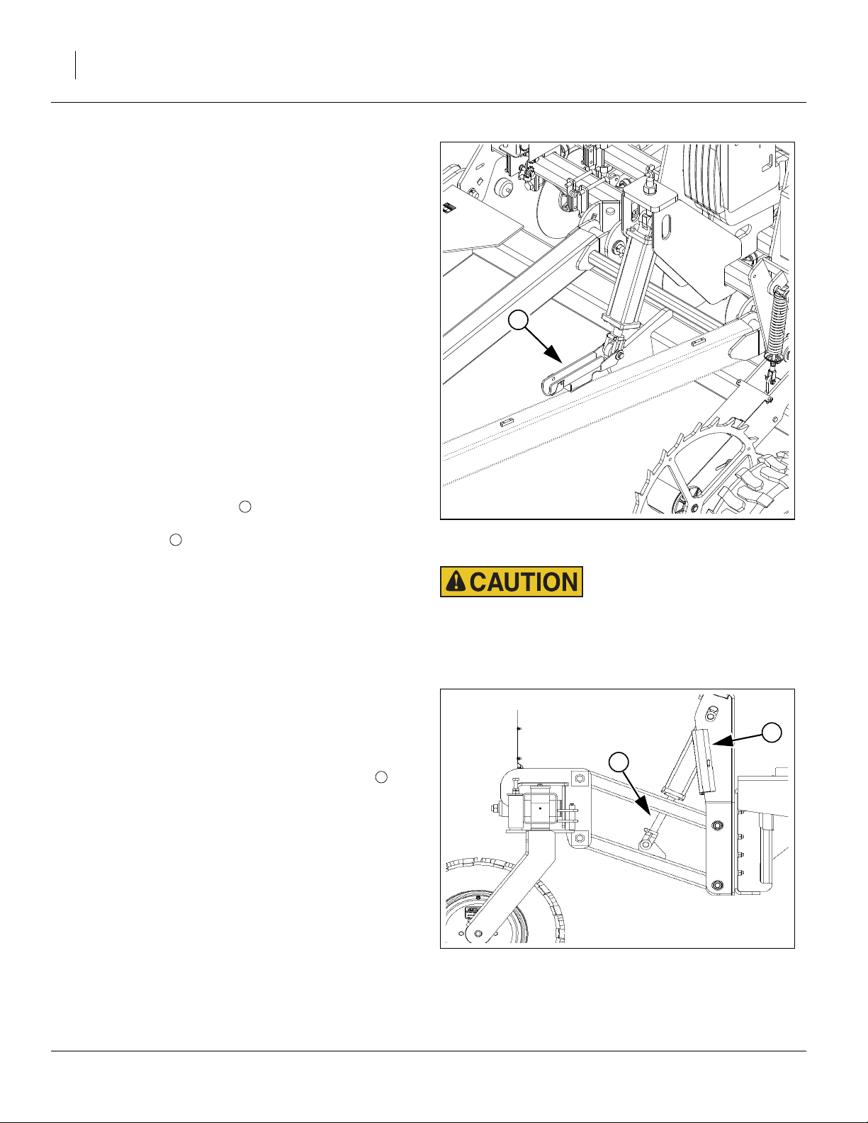
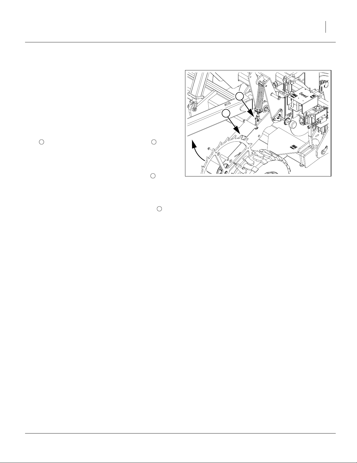
1
Ground Drive Lock-Up
On a drill with Native Grass, both left and right ground
drives will be operating unless one is disengaged.
To disengage, disconnect the ground drive spring rod of
the unused drive is from its normal (inner) operating
1 2
lug , and reconnect it to a (outer) hold-up lug . This
operation requires a hoist or jack.
Refer to Figure 11
1. Raise the drill and install lift locks (page 18).
2
2. Loosen the nut at the lower spring rod bolt .
3. Hoist or jack up the ground drive arm until the lower
bolt is loose. Remove the nut, washer and bolt.
4. Hoist or jack the arm up again until the spring rod
clevis is aligned with the hole in the outer lug of
the arm.
5. Insert the bolt, and secure with washer and nut.
In this configuration, the locked-up drive never touches
the ground and does not turn.
This locked-up configuration does not disengage any
chains, and may also be used to make the ground drive
easier to access for calibration (page 33).
1
2
Figure 11
Disengage Ground Drive
28470
10/06/2010 150-290M
 Loading...