

Page 1

Great Plains Mfg., Inc.
Installation Instructions
706/1006 No-Till Drill
Option Installation
Used with:
• 706 End Wheel No-Till Drill
• 1006 End Wheel No-Till Drill
General Information
TheseinstructionsexplainhowtoinstalltheSmall Grass
Seeds, Fertilizer and Native GrassSeeds options.
These instructions apply to:
133-251A 706-7 Seed to SGS in row
133-252A 706-7 Seed to SGS side del.
133-253A 706-7 1/2 & 8 Seed to SGS in row
133-254A 706-7 1/2 & 8 Seed to SGS side del.
133-255A 1006-7 Seed to SGS in row
133-256A 1006-7 Seed to SGS side del.
133-257A 1006-7 1/2 Seed to SGS in row
133-258A 1006-7 1/2 Seed to SGS side del.
133-259A 1006-8 Seed to SGS in row
133-260A 1006-8 Seed ti SGS side del.
133-261A 706-7 NG to SGS in row
133-262A 706-7 NG to SGS side del.
133-263A 706-7 1/2&8NGtoSGSinrow
133-264A 706-7 1/2&8NGtoSGSside del.
133-265A 1006-7 NG to SGS in row
133-266A 1006-7 NG to SGS side del.
133-267A 1006-7 1/2 NG to SGS in row
133-268A 1006-7 1/2 NG to SGS side del.
133-269A 1006-8 NG to SGS in row
133-270A 1006-8 NG to SGS side del.
133-271A 706-7 Fert. to SGS in row
133-272A 706-7 Fert. to SGS side del.
133-273A 706-7 1/2&8Fert.toSGSinrow
133-274A 706-7 1/2&8Fert.toSGSside del.
133-275A 1006-7 Fert. to SGS in row
133-276A 1006-7 Fert. to SGS side del.
133-277A 1006-7 1/2 Fert. toSGS inrow
133-278A 1006-7 1/2 Fert. toSGS sidedel.
133-279A 1006-8 Fert. to SGS in row
133-280A 1006-8 Fert. to SGS side del.
142-920A 706-7 Seed to Fert.
142-921A 706-7 1/2 & 8 Seed to Fert.
142-922A 1006-7 Seed to Fert.
142-923A 1006-7 1/2 Seed to Fert.
142-924A 1006-8 Seed to Fert.
142-925A 706-7 Seed & SGS to Fert.
142-926A 706-7 1/2 & 8 Seed & SGS to Fert.
142-927A 1006-7 Seed & SGS to Fert.
142-928A 1006-7 1/2 Seed & SGS to Fert.
142-929A 1006-8 Seed & SGS to Fert.
© Copyright 2004 Printed
8/2/2005
When you see this symbol, the subsequent instructions and
warnings areserious- follow without exception. Your life and
!
!
the lives of others depend on it!
142-930A 706-7 Seed to Fert. & SGS
142-931A 706-7 1/2 & 8 Seed to Fert. &SGS
142-932A 1006-7 Seed to Fert. & SGS
142-933A 1006-7 1/2 Seed to Fert. &SGS
142-934A 1006-8 Seed to Fert. & SGS
202-546A 706-7 Seed to NG
202-547A 706-7 1/2 & 8 Seed to NG
202-548A 1006-7 Seed to NG
202-549A 1006-7 1/2 Seed to NG
202-550A 1006-8 Seed to NG
202-563A 706-7 Seed & SGS to NG
202-564A 706-7 1/2 & 8 Seed & SGS to NG
202-565A 1006-7 Seed & SGS to NG
202-566A 1006-7 1/2 Seed & SGS to NG
202-567A 1006-8 Seed & SGS to NG
202-569A 706-7 Seed to NG & SGS
202-570A 706-7 1/2 & 8 Seed to NG & SGS
202-571A 1006-7 Seed to NG & SGS
202-572A 1006-7 1/2 Seed to NG & SGS
202-573A 1006-8 Seed to NG & SGS
Manual Update
Refer to the 706/1006 No-Till Drill operator’s manual for detailed information on safely operating, adjusting,
troubleshooting and maintaining the various options mentioned in this installation manual.Refer to theparts manual
for part identification. Refer to the seed ratebook for setup,
calibration and seed rates.
150-285M Operator’sManual
150-285P Parts Manual
150-285B Seed Rate Book
Before You Start
Pages23 through 40 are adetailed listing ofparts included
in the various option packages. Use these lists to inventory
parts received. Detailed illustrationsof sprock configurations for the various option packages arelocated onpages
17 through 22.
Tools Required
• Basic hand tools
Definitions
Right-hand and left-hand as used in this manual are determined by facing the direction themachine willtravel while in
use unless otherwise stated.
151-118M
Page 2
Option Installation
2
Assembly Instructions
Great Plains Mfg., Inc.
Small Grass Seed
1. Lower drill to the ground.
2. Remove walkboard, walkboard mounts and
walkboard supports. Save hardware.
3. Remove and save all box handles and hardware.
4. Assemble new walkboardend panelsand
harrowsupports. Re-attach existingladder to
left-hand walkboard end using hardware removed in step 2.
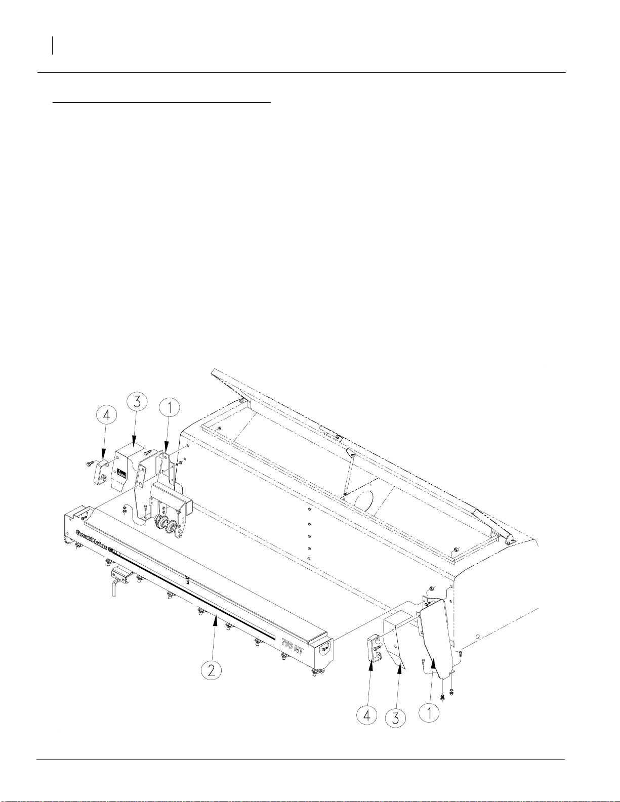
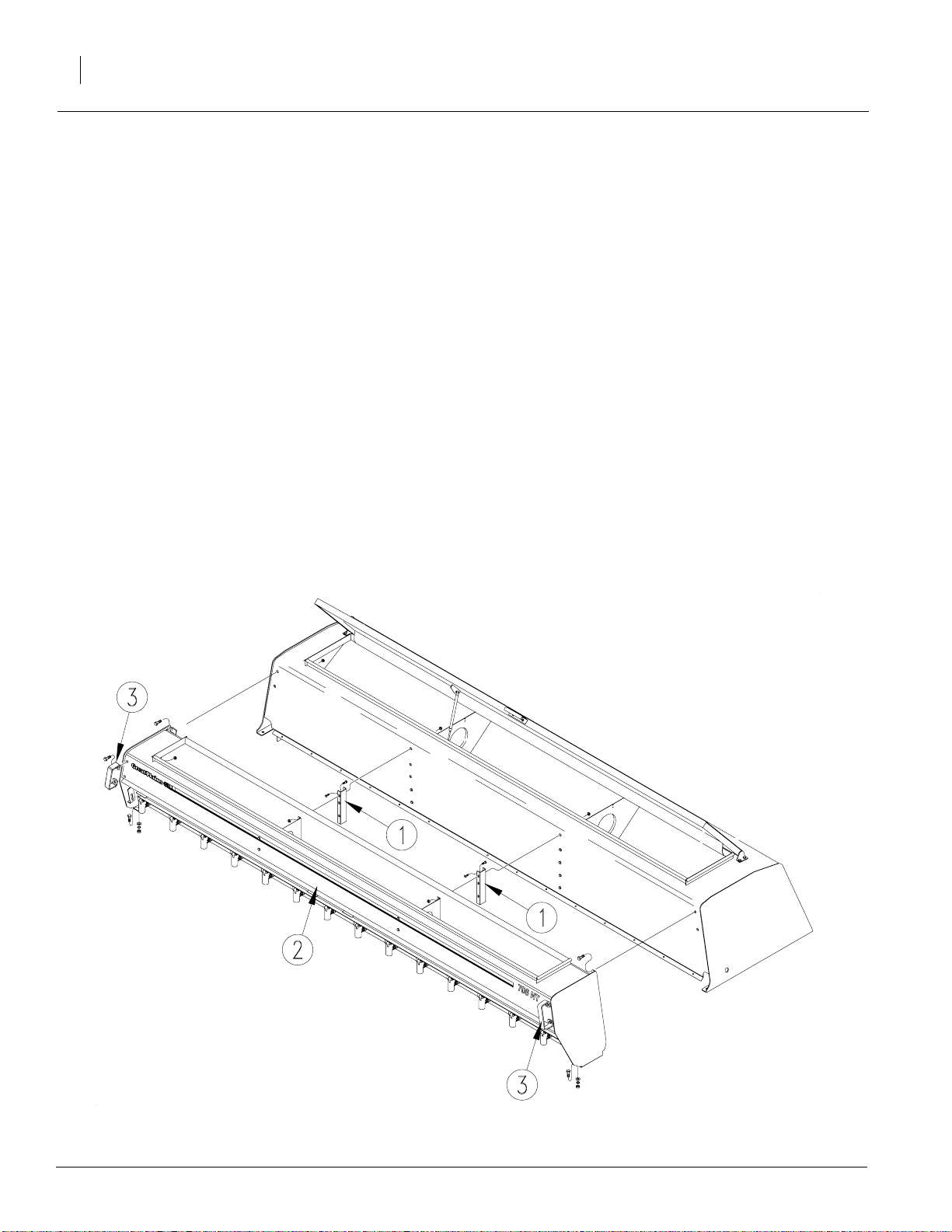
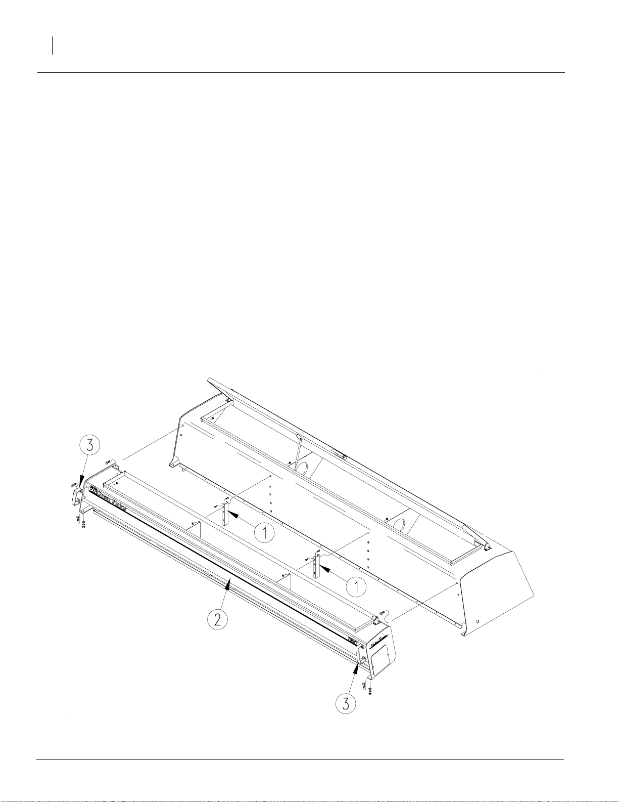
Refer to Figure 1
5. Assemblethesmallgrassseed box mounting
brackets (1) to the back of the drill box, fertilizer box or native grass seed box asshown.
Use 1/2" x 1 1/4" bolts and 1/2" flange lock
nuts to attach to the box. Use 1/2" x 1" bolts,
1/2" lock washers and 1/2" nuts to attach the
bracket to the drill frame.
6. Mount the small grass seed box (2) to the
mounting brackets (1) using 3/8" x 1" bolts,
3/8" lock washers and 3/8" nuts.
22556
Figure 1
Small Grass Seed Box
151-118M 8/2/2005
Page 3
Great Plains Mfg., Inc.
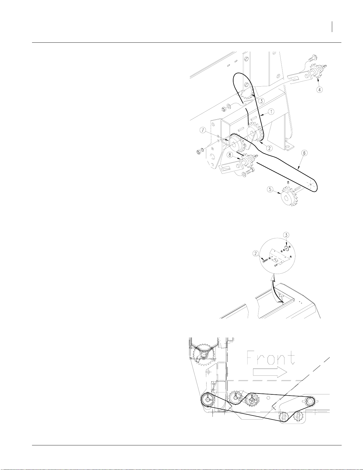
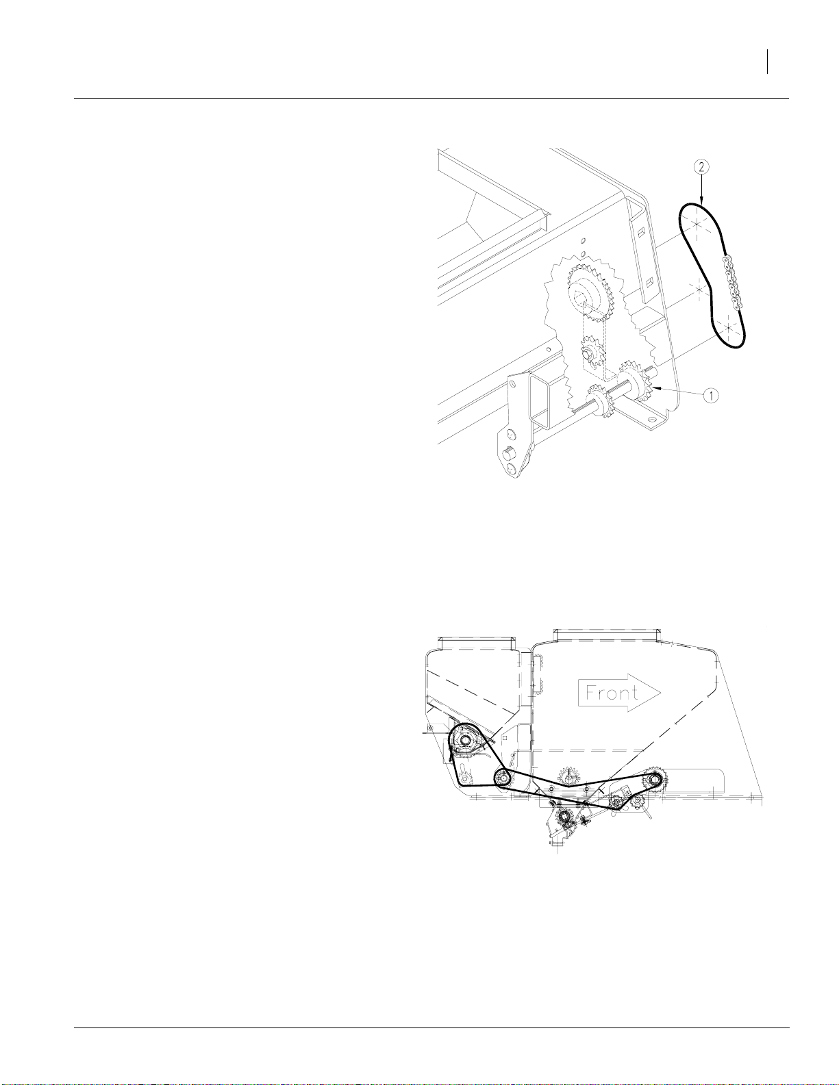
Refer to Figure 2
7. Assemble and route the chain (1) from the
sprocket (2) on the drive bracket to the
sprocketon the small grass seed box(3). Adjust idler (4) to remove chain slack.
NOTE:With fertilizer and/or seed box agitatoroptions already installed, alarge portionof the drive
is already completed.
With Fertilizer
Refer to Figure 2
8. Add 17 tooth sprocket (5) to the fertilizer box
shaft. Assemble and route chain (6) from
sprocket (5) to the sprocket (7) on the drive
bracket. Adjust idler (8) to remove chain
slack.
Installation Instructions
3
With Seed Box Agitator
Refer to Figure 3
9. Remove the current bolt and hardware from
the rear hole of the seed box and install the
agitator idler bolt (2), jamnut, flatwasher and
idlersprocket(3) into the rear hole of the false
end panel on the left-hand side of the seed
box.
Refer to Figure 4
10. Replacethe agitator drive chain with the longer one provided. Route chain as shown and
adjust idlers to remove chain slack.
22557
Figure 2
Chain Routing
21831
Figure 3
Idler Sprocket
11. Attach the chain guards and the handles removedin 3tothemounting bracketsusing the
hardware removed instep 3on page2.
8/2/2005
22558
Figure 4
Chain Routing
151-118M
Page 4
Option Installation
4
Great Plains Mfg., Inc.
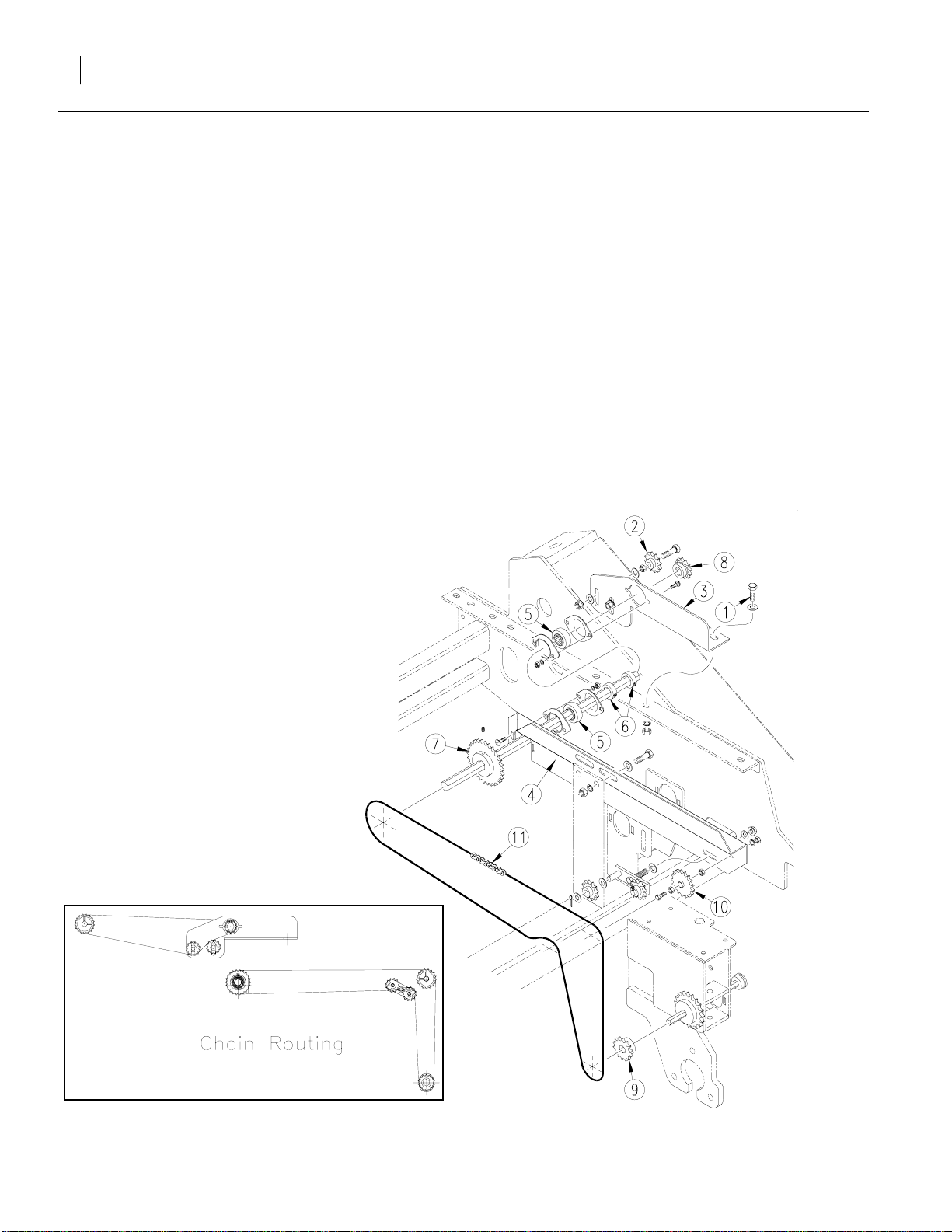
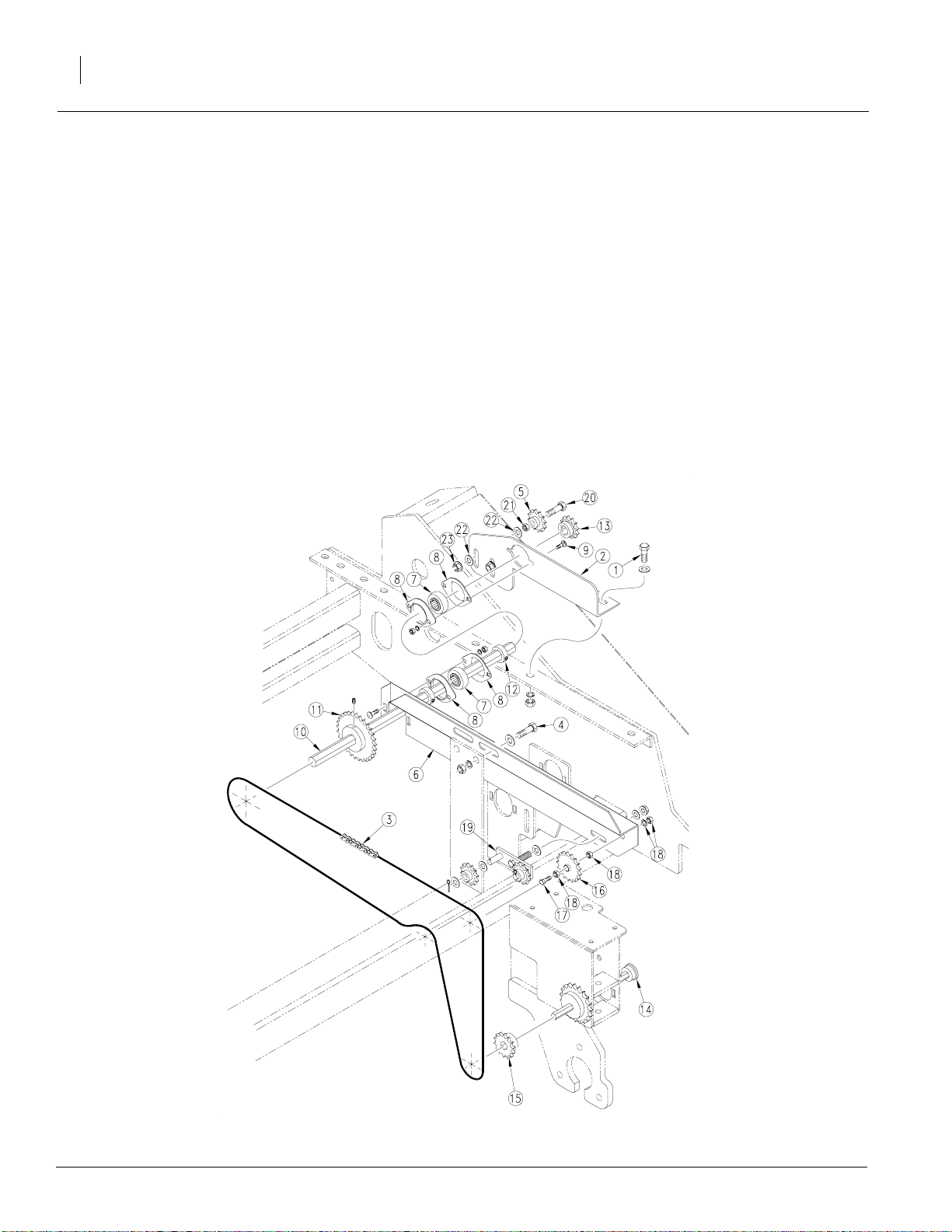
Without Fertilizer or Seed Box Agitator and
Drills with Native Grass Seed
Refer to Figure 5
12. Working at the front left side of the drill, remove the second and third front 1/2"x 11/4"
long bolts (1) that jointhe boxto the frame. Install the idler (2) 1/2" x 3" long bolt, 1/2" flat
washer,1/2" jam nut and 1/2" flange lock nut
to bracket (3) as shown.
13. Install bracket (3) and (4) as shown.Leave
loose until final assembly. Install the 7/8" hex
bore bearings (5) and flangettes with 5/16" x
1" carriage bolts and hardware as shown on
plates (3) and (4). Be careful to place the
bearings on the side of the plate as illustrated.
14. Slide the 7/8" hexjackshaft and 7/8"hexlocking collars (6) on theinside between the bear-
ings. Place the 22 tooth sprocket (7)on the
inboard side of the shaft and the 12 tooth
sprocket(8) on theout boardside of theshaft.
15. Add14tooth sprocket(9)to the gearboxdriver
shaft already installed on the drill.
16. Attach the 17 tooth idler sprocket (10) with
5/8" x 3 1/2" bolt, with 5/8" jam nuts and 5/8"
flat washer as shown on plate (4).
17. Align the 7/8"hex shaft frontto back and level
with the drill. Tighten brackets (3) and (4).
Alignsprocketsandidlersonplate(4) and add
chain (11) and route as shown.
18. Add chain between sprocket (8) and the
sprocket on the drive bracket for thesmall
grass seed drive, route chain as shownand
tighten with idler (2).
22596
Figure 5
Lower Drive Assembly
151-118M 8/2/2005
22597
Page 5
Great Plains Mfg., Inc.
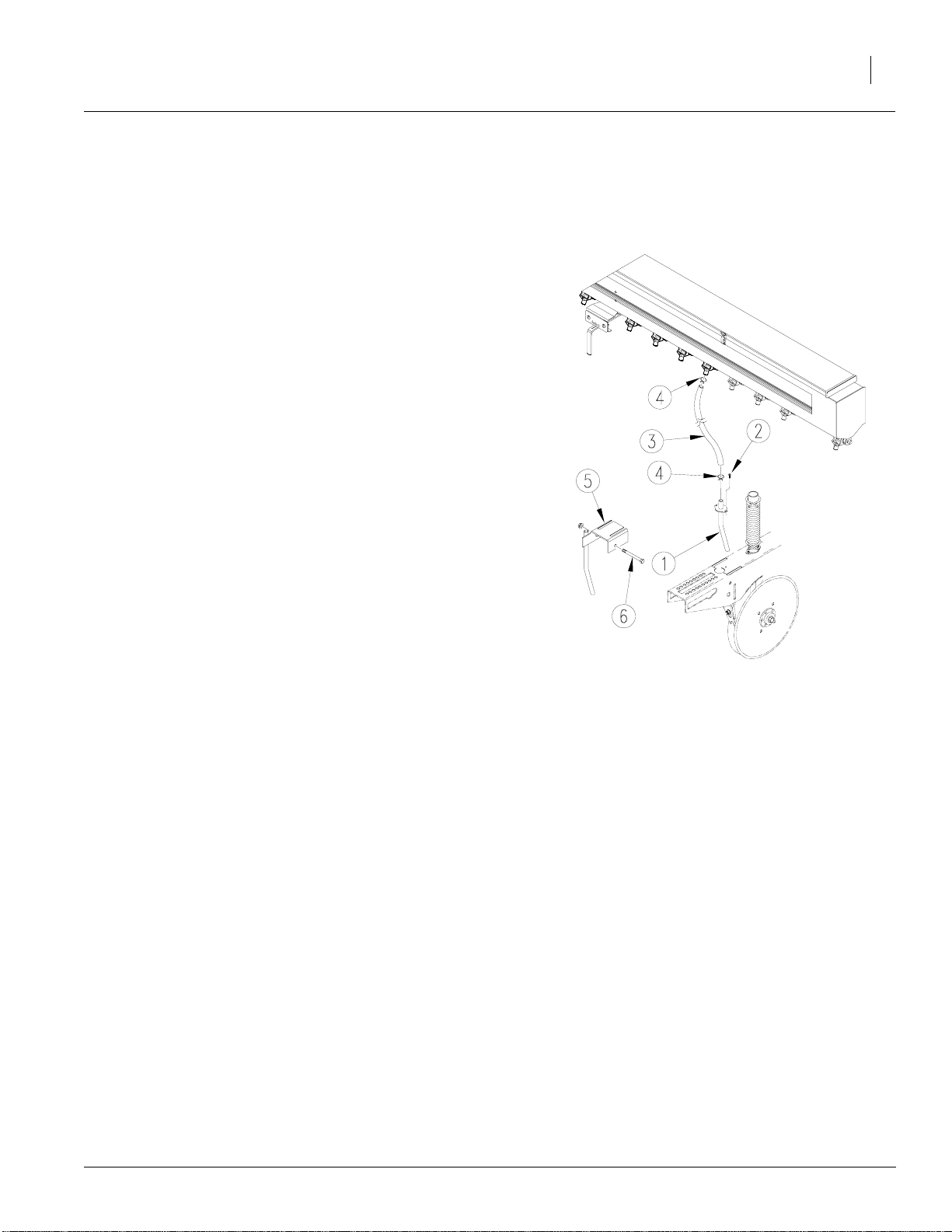
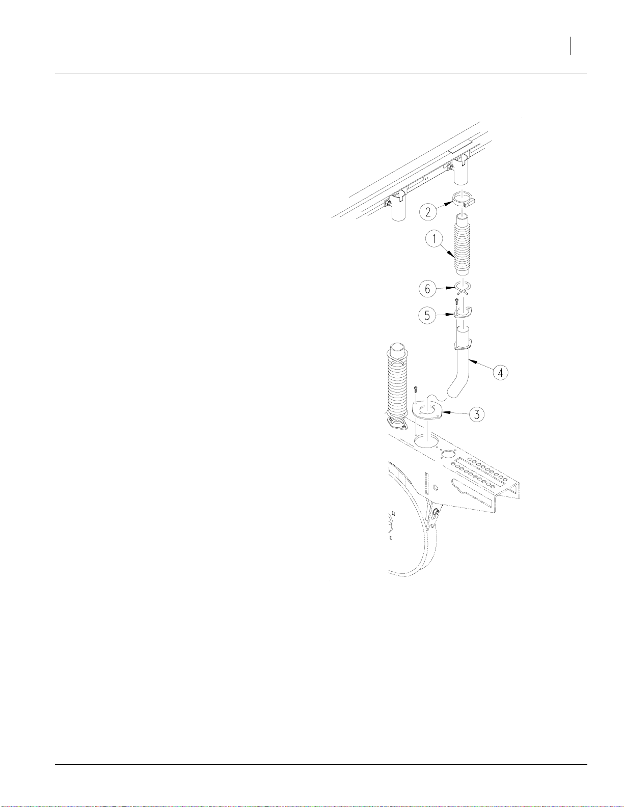
Seed Tube Assembly
The openers on the 706/1006 havetwo locations
for small grass delivery. In row or side delivery.
The in row delivery is installed in the rear opener
holewhile the side delivery attaches to theside of
the opener.
Refer to Figure 6
19. Insert the seed tube (1) into the hole on the
topof the opener.Secure in place with a number 10-16 x 1/2” screw (2).
20. Slidea hose clamp(4)overthehose(3). Slide
the end of the hose over the seed tube and
secure it in place with the hose clamp.
21. Slide a hose clamp (4) over the other end of
thehoseandslidethehoseoverthe seed outlet which corresponds with the appropriate
opener. Secure hose in place with the hose
clamp. Repeat the above steps to install the
rest of the seed tubes and hoses.
Installation Instructions
5
22. Set the side delivery tube (5) down over the
top of the opener directly in front of the fertilizer tube. Line up the holes with the holes in
theopener and insert the 3/8”x35/8” boltand
secure bolt with a 3/8” lock nut flange.
23. Slidea hose clamp(4)overthehose(3). Slide
the end of the hose over the seed tube and
secure it in place with the hose clamp.
24. Slide a hose clamp (4) over the other end of
thehoseandslidethehoseoverthe seed outlet which corresponds with the appropriate
opener. Secure hose in place with the hose
clamp. Repeat the above steps to install the
rest of the seed tubes and hoses.
Walkboard Assembly
25. Assemble walkboard on the end panels and
walkboardsupports using hardwareremoved
in step 2 on page 2.
26. Attach SMV sign andadd allsafetyand warning decals to the walkboard.
27. Referto yourGreatPlainsseed rate book and
operator’smanual for setup, calibration and
use.
22559
Figure 6
Seed Tube Assembly
8/2/2005
151-118M
Page 6
Option Installation
6
Great Plains Mfg., Inc.
Fertilizer Box
1. Lower drill to the ground.
2. Remove walkboard, walkboard mounts and
walkboard supports. Save hardware.
3. Remove and save all box handles and hardware.
4. Assemble new walkboardend panelsand
harrowsupports. Re-attach existingladder to
left-hand walkboard end using hardware removed in step 2.
Refer to Figure 7
5. Attach the fertilizer box mountbrackets(1) to
the fertilizerbox (2) where the fertilizer box
partitions arelocated. Use thebolts and nuts
holding the partitions.
6. Mount the fertilizer box (2) to theseed boxusing 1/2" x1 1/4" boltsand 1/2" flangenuts on
the outside ends.Use existing bolts and nuts
from the seed box partitions toattach thebox
mount brackets (1). Use 1/2" x 1" bolts, 1/2"
lock washers and 1/2" nuts to attach the box
to the drill frame.
7. Attach the handles (3) removed in step 3 to
the fertilizerbox (2) using the hardware removed in step 3.
22560
Figure 7
Fertilizer Box
151-118M 8/2/2005
Page 7
Great Plains Mfg., Inc.
With Seed Box Agitator
Refer to Figure 8
8. Install the 17 tooth sprocket (1) onthe end of
the fertilizerjackshaft. Align it with the fertilizer drivesprocket on the end to the shaft.
Route the 103 pitch chain (2) and remove
slack with the idler sprocket.
Installation Instructions
7
Refer to Figure 9
9. Replacethe agitator drive chain with the longer one provided. Route chain as shown and
adjust idlers to remove chain slack.
22615
Figure 8
Sprocket and Chain
22614
8/2/2005
Figure 9
Chain Routing
151-118M
Page 8
Option Installation
8
Great Plains Mfg., Inc.
Without Seed Box Agitator
Refer to Figure 10
10. Working at the front left side of the drill, remove the second and third front 1/2"x 11/4"
long bolts (1) that jointhe boxto the frame. Install the idler (5) 1/2" x 3" long bolt (20), 1/2"
flat washer, 1/2" jam nut and 1/2" flange lock
nut (23) to bracket (2)as shown.
11. Install bracket (2) and (6) as shown.Leave
loose until final assembly. Install the 7/8" hex
borebearings(7)andflangettes(8) with5/16"
x 1" round head square neck bolts (9) and
hardware as shown on plates(2) and (6). Be
carefulto place thebearingsonthe side ofthe
plate as illustrated.
12. Slide the 7/8" hexjackshaft and 7/8"hexlocking collars (12) on the inside between the
bearings. Place the 22 tooth sprocket (11) on
the inboard side of the shaft and the 12 tooth
sprocket (13) on the out board side of the
shaft.
13. Add14tooth sprocket(15)tothegearboxdriver shaft already installed on the drill.
14. Attach the 17 tooth idler sprocket (16) with
5/8" x 3 1/2" bolt (17), with 5/8" jam nuts (18)
and 5/8" flat washer as shown on plate (6).
15. Align the 7/8"hex shaft frontto back and level
with the drill. Tighten brackets (2) and (6).
Alignsprocketsandidlersonplate(6) and add
chain (3) and route as shown.
16. Add chain between sprocket (13) and the
sprocket on the drive bracket for thesmall
grass seed drive and tighten with idler (5).
21830
Figure 10
Lower Drive Assembly
151-118M 8/2/2005
Page 9
Great Plains Mfg., Inc.
Seed Tube Assembly
Refer to Figure 11
17. Attach the fertilizer hoses (1) to the drop
tubes on the fertilizer box with ratchet clamps
(2).
18. Route the hosesbehind the rearframe tubes
on the drill. Attach the opener adapter (3) to
the large hole in the opener and secure in
place with 10 x 3/8" machine screws.
19. Insert the fertilizer tube (4) into the opener
adapter (3) with the tube opening facing forward.Secure in place with reinforcement ring
(5) and 10 x 3/8" machine screws.
NOTE:If smallseedsarenotbeing used youhave
the option of using the rear most opener hole for
yourpreference infertilizerplacement.insert tube
(4) into the smaller hole. Attach with reinforcement ring (5) and 10 x 3/8" machine screws.
20. Attach the fertilizer hoses (1) to the fertilizer
tubes using hose clamp (5).
Installation Instructions
9
Walkboard Assembly
21. Assemble walkboard on the end panels and
walkboardsupports using hardwareremoved
in step 2 on page 6.
22. Attach SMV sign andadd allsafetyand warning decals to the walkboard.
23. Referto yourGreatPlainsseed rate book and
operator’smanual for setup, calibration and
use.
22565
Figure 11
Seed Tube Assembly
8/2/2005
151-118M
Page 10
Option Installation
10
Great Plains Mfg., Inc.
Native Grass
1. Lower drill to the ground.
2. Remove walkboard, walkboard mounts and
walkboard supports. Save hardware.
3. Remove and save all box handles and hardware.
4. Assemble new walkboardend panelsand
harrowsupports. Re-attach existingladder to
left-hand walkboard end using hardware removed in step 2.
Refer to Figure 12
5. Attach the native grass seed box mount
brackets (1) to the native grass seed box (2)
where the native grass seed box partitions
are located. Use the bolts and nuts holding
the partitions. (On 706NT models, these
brackets are not used.)
6. Mount the native grass seed box (2) to the
seed box using 1/2" x 1 1/4" bolts and 1/2"
flange nuts on the outside ends. Use existing
bolts and nuts from the seed box partitions to
attach the box mount brackets (1). Use 1/2" x
1" bolts, 1/2" lock washers and 1/2" nutsto attach the box to the drill frame.
7. Attachthehandles (3) removedin step 3 tothe
native grass seed box (2) using the hardware
removed in step 3.
Native Grass Seed Drive
8. Support right-handdrill and gaugewheel arm
by blocking upwith jacks and supports. Remove gauge wheel tire.
22566
Figure 12
Native Grass Seed Box
151-118M 8/2/2005
Page 11
Great Plains Mfg., Inc.
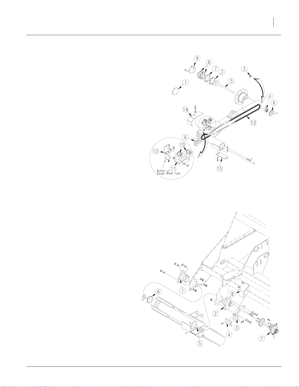
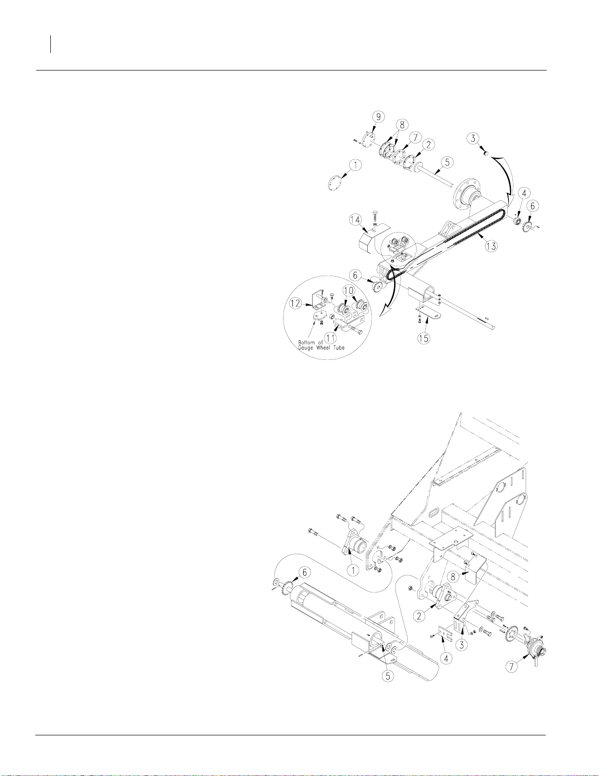
Refer to Figure 13
9. Access drivegauge wheelhub by removing
endcap(1). Be careful and leavethe hub seal
(2) in place.Removeplastic cap (3)on the inside end of the gauge wheel spindle. Insert
spindle bearing (4) into the area where the
plastic cap (3) was removed.Make sure the
set screws are accessible.
10. Insert right-hand lockout driveshaft (5)
throughdrivespindle,throughbearing(4)and
through 19 tooth sprocket (6). The sprocket
will be located inside the gauge wheel arm.
Lock set screws on bearing.
11. Addlockouthub spacer (7), lockouthubseals
(8) and lockout end cap (9).
12. Assemble the idler assemblyusing one roller
(10), 1/2" x 2" bolt and 1/2" jam nut through
the hole nearest the cross piece on the idler
arm (11) as shown.Place 3/8"flat washer
overthe pivotshaft on idler mount (12). Place
the other roller (10) between the remaining
holes in arm (11). Insert pivot shaft on idler
mount (12) through the arm and roller and insert cotter pin in end of shaft.
Installation Instructions
Figure 13
Gauge Wheel Assembly
11
22572
13. Mount idler assembly to thebottom of gauge
wheeltubeasshown.Thread the 5/8" jam nut
on to the 5/8" x 3 1/2" square head screw.
Threadtheidler adjustment into the top of the
gauge wheel tube.
Refer to Figure 14
14. Withthe gaugewheelarmsupported,remove
the pivot castings one at a time and replace
with 1" bore bearings (1) and (2). Place the
shorter one (1) in the outboard position and
use existing hardware.Place the longer casting (2) in the inboard position along with the
right-hand clutch mount (3) as shown.Use
5/8" x 2 1/2" bolts, 5/8" flat washers and 5/8"
lock nuts.
15. Attach clutch adjuster(4) to the clutch mount
(3) with a 3/8" x 3/4" carriage bolt, 3/8" lock
washer and 3/8" nut.
16. Insert the gauge wheel jackshaft (5) through
the outboard bearing. Add 19 tooth sprocket
(6) to the shaft so it is inside of the gauge
wheel tube. Add one 1" flat washer and roll
pin on the outboard end. Slide shaft inward
through the other bearing until the washer
rest against the outboard bearing. Lock set
screws to hold jackshaft in place.
22573
Figure 14
Pivot Castings
8/2/2005
151-118M
Page 12
Option Installation
12
Refer to Figure 15
17. Alignthe two 19 tooth sprockets (6) with each
other and tighten theset screws to holdthem
in place.
18. Feed the 188 pitch chain (13) through the
gauge wheel tube and around the sprockets
and idler assembly.
19. Adjust the square head idler adjustment
screw to give tension to the chain. Place the
access cover (14) over the hole andsecure it
and the adjustment screw in place with the
jam nut.
20. Attach the clutch adjuster (15) to the bottom
of the gauge wheel weldment with 3/8" x
11/4" bolts and3/8"flat washers.Leaveloose
at this time.
Great Plains Mfg., Inc.
Refer to Figure 16
21. Attach the 25 tooth sprocket and clutch tabs
to the clutch assembly (7) as shown.
22. Slide the clutch assembly (7) on to the shaft
with the sprocket towards the outboard side.
With the bottom clutch adjuster loose, position the clutch so the outboard tab will fit into
the square slot of the bottom clutch adjuster
andtheinboardtab will fit into the open slot of
adjuster (4). Tighten bottom clutch adjuster.
23. Align the hole in the end of the shaft with the
hole in the clutch end and insert roll pin.
24. Place clutch shield (8) over clutch and hold it
in place with 1/4" x 1/2" thumb screws.
22572
Figure 15
Gauge Wheel Assembly
22573
Figure 16
Clutch Assembly
151-118M 8/2/2005
Page 13

Great Plains Mfg., Inc.
Refer to Figure 17
25. Mount the gearbox (1) to the frame using 3/8"
x 1" self tapping screws. Make sureit is
square with the frame.
26. Slide the 19tooth spline boresprocket(2) on
the rear inboard shaft and secure it in place
with an external snap ring.
27. Slide the 25 tooth clutch sprocket (3) on the
outboard shaft and secure it in place with an
external snap ring.
28. Slide the acremeter mount (4) on the front
outboard shaft and secure it in place with an
externalsnapring. Bolt the acremeter hub (5)
to the acremeter mount (4) with 1/4" x 5/8"
bolts and 1/4" flat washers. Thread the
acremeter (6) on to the acremeter hub (5).
29. Add two 12 tooth idler sprockets (7) to the
frame using 1/2" x 3" bolt, 1/2" jam nut, 1/2"
flat washers and1/2" flange lock nut oneach
one.
30. Routethe96pitchchain(8)aroundtheclutch
(9)and sprocket(3) andremoveslackin chain
with idler.
22594
Installation Instructions
Figure 17
Gearbox
13
Refer to Figure 18
31. Assemble the 7/8" hex bearings (1) and
flangettes.Mount them to the outside surface
of the mounting platesas shown. Use 5/16" x
1" carriage bolts, 5/16" flat washers, 5/16"
lock washers and 5/16" nuts.
32. Insert the 7/8" hex shaft (2) into the one of the
bearings keeping the end with the holes towards the inboardside. Slide on both locking
collars (3) and continue to slide the shaft
through the other bearing making sure both
holes are throughthe inboard bearing.Insert
the roll pin into the hole closest the center.
33. The sprockets that assemble tothe drive
shaft (2) are 15 tooth through 24 tooth (11).
Select one (4) and addit to theshaft with the
sprockethubresting against the rollpin. Hold
sprocketin placewith a lynchpin.The remainingsprocketsare stored on the round storage
bars on the end of the frame held on with retaining clips.
22595
Figure 18
Drive Shaft
8/2/2005
151-118M
Page 14

Option Installation
14
34. Align sprocket (4) with the sprocket on the
gearbox. Slide both of the locking collars (3)
against the bearings (1) and tighten set
screws.Makesure sprocket(4)is still aligned
with the sprocket on the gearbox.
35. Add two idlers(5) to the frame plateusing using 1/2" x 3" bolt, 1/2" jam nut, 1/2" flat washers and 1/2" flange lock nut on each one.
36. Route108 pitch chain (8) around the gearbox
sprocket and sprocket (4) and tighten with
idlers (5).
37. Add a 24 tooth sprocket with set screws (7) to
the outboard end of shaft (2). Add two idlers
(5) to the frameplate using1/2" x3" bolt,1/2"
jamnut,1/2"flat washersand 1/2" flange lock
nut on each one.
Refer to Figure 19
Great Plains Mfg., Inc.
38. Remove the right-hand access cover(1) for
the native grass seed box. Add the 30 tooth
3/4" hex sprocket (2) tothe agitatorshaft, the
17 tooth sprocket (3) tothe cup shaftand the
bearing idler sprocket (4).
Refer to Figure 18 on page 13
39. Align the 25 tooth sprocket (7) with the 30
tooth sprocket at the nativegrass seed box
and tighten set screws.
Refer to Figure 20
40. Route 176 pitch chain around sprockets and
remove slack withidlers.
Refer to Figure 18 on page 13
41. Installgearboxcover(9) overgearboxmaking
sure selector handle rod sticks through the
hole in top. Secure cover in place with 3/8" x
1"selftappingscrews.Attach selector handle
(10) to the selector rod with 1/4" x 3/8",
1/4" flat washer and 1/4" lock washer.
42. Re-installgauge wheeltire.With gaugewheel
tire off the ground, clutch engaged and lockout cap in driveposition, rotatetire toengage
drive. Check to make sure all chains are turing and in alignment.
22598
Figure 19
Right-Hand of Native Grass Box
22616
Figure 20
Chain Routing
43. Install cover backon native grass seed box.
44. Remove jacks andsupports from drill. Raise
and lower the drill hydraulically making sure
the clutch engages anddisengages properly.
Adjust as needed.
45. Grease all fittings on the gauge wheel.
151-118M 8/2/2005
Page 15

Great Plains Mfg., Inc.
Native Grass Seed Tube Installation
Refer to Figure 21
46. Insert the native grass seed tube (1) in the
hole behind the springs and secure in place
with two 10-16 x 3/8" screws and 1/4" flat
washers.
47. Attach one end of the seed hose (2) to the
seedtube(1)witha#42hose clamp the other
end to the native seed cup with a #42 hose
clamp.
Walkboard Assembly
48. Assemble walkboard on the end panels and
walkboardsupports using hardwareremoved
in step 2 on page 10.
49. Attach SMV sign andadd allsafetyand warning decals to the walkboard.
Installation Instructions
15
50. Referto yourGreatPlainsseed rate book and
operator’smanual for setup, calibration and
use.
22617
Figure 21
Seed Tube
8/2/2005
151-118M
Page 16

Option Installation
16
Adding Native Grass or Fertilizer to
Drills with Seed & SGS
1. Lower drill to the ground.
2. Remove walkboard, walkboard mounts and
walkboard supports. Save hardware.
3. Disassemble small grass drive chain from
front of drill. Remove SGS box and mount
bracketsfrom rear of seed box and frame end
panels. Keep allhardware for reuse.
4. Assemble new walkboardend panelsand
harrowsupports. Re-attach existingladder to
left-hand walkboard end using hardware removed in step 2.
Great Plains Mfg., Inc.
5. To attach and assemble native grass or fertilizer box refer to appropriate corresponding
assembly instructions found in this manual.
6. Refer to small grass seeds assembly instructions found on page 2 of this manual to reassemble SGS box.
151-118M 8/2/2005
Page 17

Great Plains Mfg., Inc.
Seed Box Sprocket Configuration
Installation Instructions
17
8/2/2005
21754
151-118M
Page 18

Option Installation
18
Seed Box Agitator Sprocket Configuration
Great Plains Mfg., Inc.
21753
151-118M 8/2/2005
Page 19

Great Plains Mfg., Inc.
Small Grass Seeds Sprocket Configuration
Installation Instructions
19
8/2/2005
21755
151-118M
Page 20

Option Installation
20
Native Grass Sprocket Configuration
Great Plains Mfg., Inc.
21756
151-118M 8/2/2005
Page 21

Great Plains Mfg., Inc.
Fertilizer Sprocket Configuration
Installation Instructions
21
8/2/2005
21757
151-118M
Page 22

Option Installation
22
Fertilizer with Small Grass Seeds Box Sprocket Configuration
Great Plains Mfg., Inc.
21758
151-118M 8/2/2005
Page 23

Great Plains Mfg., Inc.
133-251A 706-7 Seed to SGS in row delivery
Your kit includes:
Qty. Part No. Part Description
1 119-306L 706 SEED & SGS WALKBOARD A
1 133-227L 706-7" SGS BOX ASSY
1 133-243L 706 SGS DRIVE BUNDLE
11 133-249L SGS OPENER IN-ROW BUNDLE
1 151-118M MANUAL 706/1006 OPTION INS
133-252A 706-7 Seed to SGS side delivery
Your kit includes:
Qty. Part No. Part Description
Installation Instructions
23
1 119-306L 706 SEED & SGS WALKBOARD A
1 133-227L 706-7" SGS BOX ASSY
1 133-243L 706 SGS DRIVE BUNDLE
11 133-250L SGS OPENER SIDE DELIVERY B
1 151-118M MANUAL 706/1006 OPTION INS
133-253A 706-7 1/2 & 8 Seed to SGS in row delivery
Your kit includes:
Qty. Part No. Part Description
1 119-306L 706 SEED & SGS WALKBOARD A
1 133-228L 706-7 1/2-8" SGS BOX ASSY
1 133-243L 706 SGS DRIVE BUNDLE
10 133-249L SGS OPENER IN-ROW BUNDLE
1 151-118M MANUAL 706/1006 OPTION INS
133-254A 706-7 1/2 & 8 Seed to SGS side delivery
Your kit includes:
Qty. Part No. Part Description
1 119-306L 706 SEED & SGS WALKBOARD A
1 133-228L 706-7 1/2-8" SGS BOX ASSY
1 133-243L 706 SGS DRIVE BUNDLE
10 133-250L SGS OPENER SIDE DELIVERY B
1 151-118M MANUAL 706/1006 OPTION INS
151-118M8/2/2005
Page 24

Option Installation
24
133-255A 1006-7 Seed to SGS in row delivery
Your kit includes:
Qty. Part No. Part Description
1 119-307L 1006 SEED & SGS WALKBOARD
1 133-229L 1006-7" SGS BOX ASSY
1 133-246L 1006 SGS DRIVE BUNDLE
16 133-249L SGS OPENER IN-ROW BUNDLE
1 151-118M MANUAL 706/1006 OPTION INS
133-256A 1006-7 Seed to SGS side delivery
Your kit includes:
Qty. Part No. Part Description
Great Plains Mfg., Inc.
1 119-307L 1006 SEED & SGS WALKBOARD
1 133-229L 1006-7" SGS BOX ASSY
1 133-246L 1006 SGS DRIVE BUNDLE
16 133-250L SGS OPENER SIDE DELIVERY B
1 151-118M MANUAL 706/1006 OPTION INS
133-257A 1006-7 1/2 Seed to SGS in row delivery
Your kit includes:
Qty. Part No. Part Description
1 119-307L 1006 SEED & SGS WALKBOARD
1 133-230L 1006-7 1/2" SGS BOX ASSY
1 133-246L 1006 SGS DRIVE BUNDLE
15 133-249L SGS OPENER IN-ROW BUNDLE
1 151-118M MANUAL 706/1006 OPTION INS
133-258A 1006-7 1/2 Seed to SGS side delivery
Your kit includes:
Qty. Part No. Part Description
1 119-307L 1006 SEED & SGS WALKBOARD
1 133-230L 1006-7 1/2" SGS BOX ASSY
1 133-246L 1006 SGS DRIVE BUNDLE
15 133-250L SGS OPENER SIDE DELIVERY B
1 151-118M MANUAL 706/1006 OPTION INS
151-118M 8/2/2005
Page 25

Great Plains Mfg., Inc.
133-259A 1006-8 Seed to SGS in row delivery
Your kit includes:
Qty. Part No. Part Description
1 119-307L 1006 SEED & SGS WALKBOARD
1 133-231L 1006-8" SGS BOX ASSY
1 133-246L 1006 SGS DRIVE BUNDLE
14 133-249L SGS OPENER IN-ROW BUNDLE
1 151-118M MANUAL 706/1006 OPTION INS
133-260A 1006-8 Seed to SGS side delivery
Your kit includes:
Qty. Part No. Part Description
Installation Instructions
25
1 119-307L 1006 SEED & SGS WALKBOARD
1 133-231L 1006-8" SGS BOX ASSY
1 133-246L 1006 SGS DRIVE BUNDLE
14 133-250L SGS OPENER SIDE DELIVERY B
1 151-118M MANUAL 706/1006 OPTION INS
133-261A 706-7 NG to SGS in row delivery
Your kit includes:
Qty. Part No. Part Description
1 133-227L 706-7" SGS BOX ASSY
1 133-245L 706 NG/SGS DRIVE BUNDLE
11 133-249L SGS OPENER IN-ROW BUNDLE
1 151-101H LH NG & SGS WALKBOARD MOUN
1 151-102H RH NG & SGS WALKBOARD MOUN
2 151-103H NG & SGS HARROW MOUNT
1 151-118M MANUAL 706/1006 OPTION INS
133-262A 706-7 NG to SGS side delivery
Your kit includes:
Qty. Part No. Part Description
1 133-227L 706-7" SGS BOX ASSY
1 133-245L 706 NG/SGS DRIVE BUNDLE
11 133-250L SGS OPENER SIDE DELIVERY B
1 151-101H LH NG & SGS WALKBOARD MOUN
1 151-102H RH NG & SGS WALKBOARD MOUN
2 151-103H NG & SGS HARROW MOUNT
1 151-118M MANUAL 706/1006 OPTION INS
8/2/2005
151-118M
Page 26

Option Installation
26
133-263A 706-7 1/2 & 8 NG to SGS in row delivery
Your kit includes:
Qty. Part No. Part Description
1 133-228L 706-7 1/2-8" SGS BOX ASSY
1 133-245L 706 NG/SGS DRIVE BUNDLE
10 133-249L SGS OPENER IN-ROW BUNDLE
1 151-101H LH NG & SGS WALKBOARD MOUN
1 151-102H RH NG & SGS WALKBOARD MOUN
2 151-103H NG & SGS HARROW MOUNT
1 151-118M MANUAL 706/1006 OPTION INS
133-264A 706-7 1/2 & 8 NG to SGS side delivery
Your kit includes:
Qty. Part No. Part Description
Great Plains Mfg., Inc.
1 133-228L 706-7 1/2-8" SGS BOX ASSY
1 133-245L 706 NG/SGS DRIVE BUNDLE
10 133-250L SGS OPENER SIDE DELIVERY B
1 151-101H LH NG & SGS WALKBOARD MOUN
1 151-102H RH NG & SGS WALKBOARD MOUN
2 151-103H NG & SGS HARROW MOUNT
1 151-118M MANUAL 706/1006 OPTION INS
133-265A 1006-7 NG to SGS in row delivery
Your kit includes:
Qty. Part No. Part Description
1 133-229L 1006-7" SGS BOX ASSY
1 133-248L 1006 NG/SGS DRIVE BUNDLE
16 133-249L SGS OPENER IN-ROW BUNDLE
1 151-101H LH NG & SGS WALKBOARD MOUN
1 151-102H RH NG & SGS WALKBOARD MOUN
2 151-103H NG & SGS HARROW MOUNT
1 151-118M MANUAL 706/1006 OPTION INS
133-266A 1006-7 NG to SGS side delivery
Your kit includes:
Qty. Part No. Part Description
1 133-229L 1006-7" SGS BOX ASSY
1 133-248L 1006 NG/SGS DRIVE BUNDLE
16 133-250L SGS OPENER SIDE DELIVERY B
1 151-101H LH NG & SGS WALKBOARD MOUN
1 151-102H RH NG & SGS WALKBOARD MOUN
2 151-103H NG & SGS HARROW MOUNT
1 151-118M MANUAL 706/1006 OPTION INS
151-118M 8/2/2005
Page 27

Great Plains Mfg., Inc.
133-267A 1006-7 1/2 NG to SGS in row delivery
Your kit includes:
Qty. Part No. Part Description
1 133-230L 1006-7 1/2" SGS BOX ASSY
1 133-248L 1006 NG/SGS DRIVE BUNDLE
15 133-249L SGS OPENER IN-ROW BUNDLE
1 151-101H LH NG & SGS WALKBOARD MOUN
1 151-102H RH NG & SGS WALKBOARD MOUN
2 151-103H NG & SGS HARROW MOUNT
1 151-118M MANUAL 706/1006 OPTION INS
133-268A 1006-7 1/2 NG to SGS side delivery
Your kit includes:
Qty. Part No. Part Description
Installation Instructions
27
1 133-230L 1006-7 1/2" SGS BOX ASSY
1 133-248L 1006 NG/SGS DRIVE BUNDLE
15 133-250L SGS OPENER SIDE DELIVERY B
1 151-101H LH NG & SGS WALKBOARD MOUN
1 151-102H RH NG & SGS WALKBOARD MOUN
2 151-103H NG & SGS HARROW MOUNT
1 151-118M MANUAL 706/1006 OPTION INS
133-269A 1006-8 NG to SGS in row delivery
Your kit includes:
Qty. Part No. Part Description
1 133-231L 1006-8" SGS BOX ASSY
1 133-248L 1006 NG/SGS DRIVE BUNDLE
14 133-249L SGS OPENER IN-ROW BUNDLE
1 151-101H LH NG & SGS WALKBOARD MOUN
1 151-102H RH NG & SGS WALKBOARD MOUN
2 151-103H NG & SGS HARROW MOUNT
1 151-118M MANUAL 706/1006 OPTION INS
133-270A 1006-8 NG to SGS side delivery
Your kit includes:
Qty. Part No. Part Description
1 133-231L 1006-8" SGS BOX ASSY
1 133-248L 1006 NG/SGS DRIVE BUNDLE
14 133-250L SGS OPENER SIDE DELIVERY B
1 151-101H LH NG & SGS WALKBOARD MOUN
1 151-102H RH NG & SGS WALKBOARD MOUN
2 151-103H NG & SGS HARROW MOUNT
1 151-118M MANUAL 706/1006 OPTION INS
8/2/2005
151-118M
Page 28

Option Installation
28
133-271A 706-7 Fert. to SGS in row delivery
Your kit includes:
Qty. Part No. Part Description
1 133-227L 706-7" SGS BOX ASSY
1 133-244L 706 FERT/SGS DRIVE BUNDLE
11 133-249L SGS OPENER IN-ROW BUNDLE
1 151-104H LH FERT & SGS WALKBOARD MO
1 151-105H RH FERT & SGS WALKBOARD MO
2 151-106H FERT & SGS HARROW MOUNT
1 151-118M MANUAL 706/1006 OPTION INS
133-272A 706-7 Fert. to SGS side delivery
Your kit includes:
Qty. Part No. Part Description
Great Plains Mfg., Inc.
1 133-227L 706-7" SGS BOX ASSY
1 133-244L 706 FERT/SGS DRIVE BUNDLE
11 133-250L SGS OPENER SIDE DELIVERY B
1 151-104H LH FERT & SGS WALKBOARD MO
1 151-105H RH FERT & SGS WALKBOARD MO
2 151-106H FERT & SGS HARROW MOUNT
1 151-118M MANUAL 706/1006 OPTION INS
133-273A 706-7 1/2 & 8 Fert. to SGS in row delivery
Your kit includes:
Qty. Part No. Part Description
1 133-228L 706-7 1/2-8" SGS BOX ASSY
1 133-244L 706 FERT/SGS DRIVE BUNDLE
10 133-249L SGS OPENER IN-ROW BUNDLE
1 151-104H LH FERT & SGS WALKBOARD MO
1 151-105H RH FERT & SGS WALKBOARD MO
2 151-106H FERT & SGS HARROW MOUNT
1 151-118M MANUAL 706/1006 OPTION INS
133-274A 706-7 1/2 & 8 Fert. to SGS side delivery
Your kit includes:
Qty. Part No. Part Description
1 133-228L 706-7 1/2-8" SGS BOX ASSY
1 133-244L 706 FERT/SGS DRIVE BUNDLE
10 133-250L SGS OPENER SIDE DELIVERY B
1 151-104H LH FERT & SGS WALKBOARD MO
1 151-105H RH FERT & SGS WALKBOARD MO
2 151-106H FERT & SGS HARROW MOUNT
1 151-118M MANUAL 706/1006 OPTION INS
151-118M 8/2/2005
Page 29

Great Plains Mfg., Inc.
133-275A 1006-7 Fert. to SGS in row delivery
Your kit includes:
Qty. Part No. Part Description
1 133-229L 1006-7" SGS BOX ASSY
1 133-247L 1006 FERT/SGS DRIVE BUNDLE
16 133-249L SGS OPENER IN-ROW BUNDLE
1 151-104H LH FERT & SGS WALKBOARD MO
1 151-105H RH FERT & SGS WALKBOARD MO
2 151-106H FERT & SGS HARROW MOUNT
1 151-118M MANUAL 706/1006 OPTION INS
133-276A 1006-7 Fert. to SGS side delivery
Your kit includes:
Qty. Part No. Part Description
Installation Instructions
29
1 133-229L 1006-7" SGS BOX ASSY
1 133-247L 1006 FERT/SGS DRIVE BUNDLE
16 133-250L SGS OPENER SIDE DELIVERY B
1 151-104H LH FERT & SGS WALKBOARD MO
1 151-105H RH FERT & SGS WALKBOARD MO
2 151-106H FERT & SGS HARROW MOUNT
1 151-118M MANUAL 706/1006 OPTION INS
133-277A 1006-7 1/2 Fert. to SGS in row delivery
Your kit includes:
Qty. Part No. Part Description
1 133-230L 1006-7 1/2" SGS BOX ASSY
1 133-247L 1006 FERT/SGS DRIVE BUNDLE
15 133-249L SGS OPENER IN-ROW BUNDLE
1 151-104H LH FERT & SGS WALKBOARD MO
1 151-105H RH FERT & SGS WALKBOARD MO
2 151-106H FERT & SGS HARROW MOUNT
1 151-118M MANUAL 706/1006 OPTION INS
133-278A 1006-7 1/2 Fert. to SGS side delivery
Your kit includes:
Qty. Part No. Part Description
1 133-230L 1006-7 1/2" SGS BOX ASSY
1 133-247L 1006 FERT/SGS DRIVE BUNDLE
15 133-250L SGS OPENER SIDE DELIVERY B
1 151-104H LH FERT & SGS WALKBOARD MO
1 151-105H RH FERT & SGS WALKBOARD MO
2 151-106H FERT & SGS HARROW MOUNT
1 151-118M MANUAL 706/1006 OPTION INS
8/2/2005
151-118M
Page 30

Option Installation
30
133-279A 1006-8 Fert. to SGS in row delivery
Your kit includes:
Qty. Part No. Part Description
1 133-231L 1006-8" SGS BOX ASSY
1 133-247L 1006 FERT/SGS DRIVE BUNDLE
14 133-249L SGS OPENER IN-ROW BUNDLE
1 151-104H LH FERT & SGS WALKBOARD MO
1 151-105H RH FERT & SGS WALKBOARD MO
2 151-106H FERT & SGS HARROW MOUNT
1 151-118M MANUAL 706/1006 OPTION INS
133-280A Fert. to SGS side delivery
Your kit includes:
Qty. Part No. Part Description
1 133-231L 1006-8" SGS BOX ASSY
1 133-247L 1006 FERT/SGS DRIVE BUNDLE
14 133-250L SGS OPENER SIDE DELIVERY B
1 151-104H LH FERT & SGS WALKBOARD MO
1 151-105H RH FERT & SGS WALKBOARD MO
2 151-106H FERT & SGS HARROW MOUNT
1 151-118M MANUAL 706/1006 OPTION INS
Great Plains Mfg., Inc.
142-920A 706-7 Seed to Fert.
Your kit includes:
Qty. Part No. Part Description
1 119-294D 706 WALKBOARD
1 142-706H FERTILIZER WALKBOARD END R
2 142-707H FERTILIZER HARROW SUPPORT
10 142-909L FERTILIZER OPENER BUNDLE
1 142-911L 706-7 1/2 & 8" TRAY ASSEMB
1 142-915L 706 FERTILIZER BOX ASSEMBL
1 142-917L 706 FERTILIZER DRIVE ASSEM
1 142-919L FERTILIZER MOUNTING HARDWA
1 151-099H LH FERT. WALKBOARD MOUNT
1 151-118M MANUAL 706/1006 OPTION INS
142-921A 706-7 1/2 & 8 Seed to Fert.
Your kit includes:
Qty. Part No. Part Description
1 119-294D 706 WALKBOARD
1 142-706H FERTILIZER WALKBOARD END R
2 142-707H FERTILIZER HARROW SUPPORT
11 142-909L FERTILIZER OPENER BUNDLE
1 142-910L 706-7" TRAY ASSEMBLY
1 142-915L 706 FERTILIZER BOX ASSEMBL
1 142-917L 706 FERTILIZER DRIVE ASSEM
1 142-919L FERTILIZER MOUNTING HARDWA
1 151-099H LH FERT. WALKBOARD MOUNT
1 151-118M MANUAL 706/1006 OPTION INS
151-118M 8/2/2005
Page 31

Great Plains Mfg., Inc.
142-922A 1006-7 Seed to Fert.
Your kit includes:
Qty. Part No. Part Description
1 119-296D 1006 WALKBOARD
1 142-706H FERTILIZER WALKBOARD END R
2 142-707H FERTILIZER HARROW SUPPORT
16 142-909L FERTILIZER OPENER BUNDLE
1 142-912L 1006-7" TRAY ASSEMBLY
1 142-916L 1006 FERTILIZER BOX ASSEMB
1 142-918L 1006 FERTILIZER DRIVE ASSE
1 142-919L FERTILIZER MOUNTING HARDWA
1 151-099H LH FERT. WALKBOARD MOUNT
1 151-118M MANUAL 706/1006 OPTION INS
142-923A 1006-7 1/2 Seed to Fert.
Your kit includes:
Installation Instructions
31
Qty. Part No. Part Description
1 119-296D 1006 WALKBOARD
1 142-706H FERTILIZER WALKBOARD END R
2 142-707H FERTILIZER HARROW SUPPORT
15 142-909L FERTILIZER OPENER BUNDLE
1 142-913L 1006-7 1/2" TRAY ASSEMBLY
1 142-916L 1006 FERTILIZER BOX ASSEMB
1 142-918L 1006 FERTILIZER DRIVE ASSE
1 142-919L FERTILIZER MOUNTING HARDWA
1 151-099H LH FERT. WALKBOARD MOUNT
1 151-118M MANUAL 706/1006 OPTION INS
142-924A 1006-8 Seed to Fert.
Your kit includes:
Qty. Part No. Part Description
1 119-296D 1006 WALKBOARD
1 142-706H FERTILIZER WALKBOARD END R
2 142-707H FERTILIZER HARROW SUPPORT
14 142-909L FERTILIZER OPENER BUNDLE
1 142-913L 1006-7 1/2" TRAY ASSEMBLY
1 142-916L 1006 FERTILIZER BOX ASSEMB
1 142-918L 1006 FERTILIZER DRIVE ASSE
1 142-919L FERTILIZER MOUNTING HARDWA
1 151-099H LH FERT. WALKBOARD MOUNT
1 151-118M MANUAL 706/1006 OPTION INS
8/2/2005
151-118M
Page 32

Option Installation
32
142-925A 706-7 Seed & SGS to Fert.
Your kit includes:
Qty. Part No. Part Description
1 133-051H SLOTTED IDLER ARM 1/2 X 3 5/8
1 136-014D CHAIN RL #40 79 PITCHES
11 142-909L FERTILIZER OPENER BUNDLE
1 142-910L 706-7" TRAY ASSEMBLY
1 142-915L 706 FERTILIZER BOX ASSEMBLY
1 142-917L 706 FERTILIZER DRIVE ASSEMBLY
1 142-919L FERTILIZER MOUNTING HARDWARE
1 151-104H LH FERT & SGS WALKBOARD MOUNT
1 151-105H RH FERT & SGS WALKBOARD MOUNT
2 151-106H FERT & SGS HARROW MOUNT
1 168-127D 3/16 X 1 KEY
1 808-170C SPKT 40B17 X 3/4 BORE W/KW&SS
1 817-025C NO. 40 12T IDLER SPKT.
1 151-118M MANUAL 706/1006 OPTION INSTALLATION
142-926A 706-7 1/2 & 8 Seed &SGS to Fert.
Your kit includes:
Great Plains Mfg., Inc.
Qty. Part No. Part Description
1 133-051H SLOTTED IDLER ARM 1/2 X 3 5/8
1 136-014D CHAIN RL #40 79 PITCHES
10 142-909L FERTILIZER OPENER BUNDLE
1 142-911L 706-7 1/2 & 8" TRAY ASSEMBLY
1 142-915L 706 FERTILIZER BOX ASSEMBLY
1 142-917L 706 FERTILIZER DRIVE ASSEMBLY
1 142-919L FERTILIZER MOUNTING HARDWARE
1 151-104H LH FERT & SGS WALKBOARD MOUNT
1 151-105H RH FERT & SGS WALKBOARD MOUNT
2 151-106H FERT & SGS HARROW MOUNT
1 168-127D 3/16 X 1 KEY
1 808-170C SPKT 40B17 X 3/4 BORE W/KW&SS
1 817-025C NO. 40 12T IDLER SPKT.
1 151-118M MANUAL 706/1006 OPTION INSTALLATION
142-927A 1006-7 Seed & SGS to Fert.
Your kit includes:
Qty. Part No. Part Description
1 133-051H SLOTTED IDLER ARM 1/2 X 3 5/8
1 136-014D CHAIN RL #40 79 PITCHES
16 142-909L FERTILIZER OPENER BUNDLE
1 142-912L 1006-7" TRAY ASSEMBLY
1 142-916L 1006 FERTILIZER BOX ASSEMBLY
1 142-918L 1006 FERTILIZER DRIVE ASSEMBLY
1 142-919L FERTILIZER MOUNTING HARDWARE
1 151-104H LH FERT & SGS WALKBOARD MOUNT
1 151-105H RH FERT & SGS WALKBOARD MOUNT
2 151-106H FERT & SGS HARROW MOUNT
1 168-127D 3/16 X 1 KEY
1 808-170C SPKT 40B17 X 3/4 BORE W/KW&SS
1 817-025C NO. 40 12T IDLER SPKT.
1 151-118M MANUAL 706/1006 OPTION INSTALLATION
151-118M 8/2/2005
Page 33

Great Plains Mfg., Inc.
142-928A 1006-7 1/2 Seed & SGS to Fert.
Your kit includes:
Qty. Part No. Part Description
1 133-051H SLOTTED IDLER ARM 1/2 X 3 5/8
1 136-014D CHAIN RL #40 79 PITCHES
15 142-909L FERTILIZER OPENER BUNDLE
1 142-913L 1006-7 1/2" TRAY ASSEMBLY
1 142-916L 1006 FERTILIZER BOX ASSEMBLY
1 142-918L 1006 FERTILIZER DRIVE ASSEMBLY
1 142-919L FERTILIZER MOUNTING HARDWARE
1 151-104H LH FERT & SGS WALKBOARD MOUNT
1 151-105H RH FERT & SGS WALKBOARD MOUNT
2 151-106H FERT & SGS HARROW MOUNT
1 168-127D 3/16 X 1 KEY
1 808-170C SPKT 40B17 X 3/4 BORE W/KW&SS
1 817-025C NO. 40 12T IDLER SPKT.
1 151-118M MANUAL 706/1006 OPTION INSTALLATION
142-929A 1006-8 Seed & SGS to Fert.
Your kit includes:
Installation Instructions
33
Qty. Part No. Part Description
1 133-051H SLOTTED IDLER ARM 1/2 X 3 5/8
1 136-014D CHAIN RL #40 79 PITCHES
14 142-909L FERTILIZER OPENER BUNDLE
1 142-914L 1006-8" TRAY ASSEMBLY
1 142-916L 1006 FERTILIZER BOX ASSEMBLY
1 142-918L 1006 FERTILIZER DRIVE ASSEMBLY
1 142-919L FERTILIZER MOUNTING HARDWARE
1 151-104H LH FERT & SGS WALKBOARD MOUNT
1 151-105H RH FERT & SGS WALKBOARD MOUNT
2 151-106H FERT & SGS HARROW MOUNT
1 168-127D 3/16 X 1 KEY
1 808-170C SPKT 40B17 X 3/4 BORE W/KW&SS
1 817-025C NO. 40 12T IDLER SPKT.
1 151-118M MANUAL 706/1006 OPTION INSTALLATION
142-930A 706-7 Seed to Fert. & SGS
Your kit includes:
Qty. Part No. Part Description
1 119-310L 706 FERTILIZER & SGS WB ASSEMBLY
1 133-227L 706 -7" SGS BOX ASSY
1 133-244L 706 FERT/SGS DRIVE BUNDLE
11 133-249L SGS OPENER IN ROW BUNDLE
11 142-909L FERTILIZER OPENER BUNDLE
1 142-910L 706-7" TRAY ASSEMBLY
1 142-915L 706 FERTILIZER BOX ASSEMBLY
1 142-917L 706 FERTILIZER DRIVE ASSEMBLY
1 142-919L FERTILIZER MOUNTING HARDWARE
1 151-118M MANUAL 706/1006 OPTION INSTALLATION
8/2/2005
151-118M
Page 34

Option Installation
34
142-931A 706-7 1/2 & 8 Seed to Fert. & SGS
Your kit includes:
Qty. Part No. Part Description
1 119-310L 706 FERTILIZER & SGS WB ASSEMBLY
1 133-228L 706-7 1/2 & 8" SGS BOX ASSY
1 133-244L 706 FERT/SGS DRIVE BUNDLE
10 133-249L SGS OPENER IN ROW BUNDLE
10 142-909L FERTILIZER OPENER BUNDLE
1 142-911L 706-7 1/2 & 8" TRAY ASSEMBLY
1 142-915L 706 FERTILIZER BOX ASSEMBLY
1 142-917L 706 FERTILIZER DRIVE ASSEMBLY
1 142-919L FERTILIZER MOUNTING HARDWARE
1 151-118M MANUAL 706/1006 OPTION INSTALLATION
142-932A 1006-7 Seed to Fert. & SGS
Your kit includes:
Great Plains Mfg., Inc.
Qty. Part No. Part Description
1 119-311L 1006 FERTILIZER & SGS WB ASSEMBLY
1 133-229L 1006-7" SGS BOX ASSY
1 133-247L 1006 FERT/SGS DRIVE BUNDLE
16 133-249L SGS OPENER IN ROW BUNDLE
16 142-909L FERTILIZER OPENER BUNDLE
1 142-912L 1006-7" TRAY ASSEMBLY
1 142-916L 1006 FERTILIZER BOX ASSEMBLY
1 142-918L 1006 FERTILIZER DRIVE ASSEMBLY
1 142-919L FERTILIZER MOUNTING HARDWARE
1 151-118M MANUAL 706/1006 OPTION INSTALLATION
142-933A 1006-7 1/2 Seed to Fert. & SGS
Your kit includes:
Qty. Part No. Part Description
1 119-311L 1006 FERTILIZER & SGS WB ASSEMBLY
1 133-230L 1006-7 1/2" SGS BOX ASSY
1 133-247L 1006 FERT/SGS DRIVE BUNDLE
15 133-249L SGS OPENER IN ROW BUNDLE
15 142-909L FERTILIZER OPENER BUNDLE
1 142-913L 1006-7 1/2" TRAY ASSEMBLY
1 142-916L 1006 FERTILIZER BOX ASSEMBLY
1 142-918L 1006 FERTILIZER DRIVE ASSEMBLY
1 142-919L FERTILIZER MOUNTING HARDWARE
1 151-118M MANUAL 706/1006 OPTION INSTALLATION
151-118M 8/2/2005
Page 35

Great Plains Mfg., Inc.
142-934A 1006-8 Seed to Fert. & SGS
Your kit includes:
Qty. Part No. Part Description
1 119-311L 1006 FERTILIZER & SGS WB ASSEMBLY
1 133-231L 1006-8" SGS BOX ASSEMBLY
1 133-247L 1006 FERT/SGS DRIVE BUNDLE
14 133-249L SGS OPENER IN ROW BUNDLE
14 142-909L FERTILIZER OPENER BUNDLE
1 142-913L 1006-7 1/2" TRAY ASSEMBLY
1 142-916L 1006 FERTILIZER BOX ASSEMBLY
1 142-918L 1006 FERTILIZER DRIVE ASSEMBLY
1 142-919L FERTILIZER MOUNTING HARDWARE
1 151-118M MANUAL 706/1006 OPTION INSTALLATION
202-546A 706-7 Seed to NG
Your kit includes:
Installation Instructions
35
Qty. Part No. Part Description
1 119-294D 706 WALKBOARD
1 142-703H 05 FERT/SGS; 06 NG WB END
2 142-704H FERT & SGS HARROW SUPPORT
1 151-100H LH NG WALKBOARD MOUNT
1 151-118M MANUAL 706/1006 OPTION INS
1 202-519L 706-7" NG BOX & TRAY ASSY
1 202-542K 706/1006 NG RH GW ASSEMBLY
1 202-543K NG GW DRIVE BUNDLE
1 202-544L NG DRIVE BUNDLE
11 202-545L NG OPENER BUNDLE
1 821-042C POWDERED GRAPHITE 1 LB BOT
1 890-807C ACREMETER 706 600 REVS
202-547A 706-7 1/2 & 8 Seed to NG
Your kit includes:
Qty. Part No. Part Description
1 119-294D 706 WALKBOARD
1 142-703H 05 FERT/SGS; 06 NG WB END
2 142-704H FERT & SGS HARROW SUPPORT
1 151-100H LH NG WALKBOARD MOUNT
1 151-118M MANUAL 706/1006 OPTION INS
1 202-520L 706-7 1/2&8" BOX & TRAY AS
1 202-542K 706/1006 NG RH GW ASSEMBLY
1 202-543K NG GW DRIVE BUNDLE
1 202-544L NG DRIVE BUNDLE
10 202-545L NG OPENER BUNDLE
1 821-042C POWDERED GRAPHITE 1 LB BOT
1 890-807C ACREMETER 706 600 REVS
8/2/2005
151-118M
Page 36

Option Installation
36
202-548A 1006-7 Seed to NG
Your kit includes:
Qty. Part No. Part Description
1 119-296D 1006 WALKBOARD
1 142-703H 05 FERT/SGS; 06 NG WB END
2 142-704H FERT & SGS HARROW SUPPORT
1 151-100H LH NG WALKBOARD MOUNT
1 151-118M MANUAL 706/1006 OPTION INS
1 202-521L 1006-7" BOX & TRAY ASSY
1 202-543K NG GW DRIVE BUNDLE
1 202-544L NG DRIVE BUNDLE
16 202-545L NG OPENER BUNDLE
1 821-042C POWDERED GRAPHITE 1 LB BOT
1 890-808C ACREMETER 1006 416 REVS
Great Plains Mfg., Inc.
202-549A 1006-7 1/2 Seed to NG
Your kit includes:
Qty. Part No. Part Description
1 119-296D 1006 WALKBOARD
1 142-703H 05 FERT/SGS; 06 NG WB END
2 142-704H FERT & SGS HARROW SUPPORT
1 151-100H LH NG WALKBOARD MOUNT
1 151-118M MANUAL 706/1006 OPTION INS
1 202-522L 1006-7 1/2" BOX & TRAY ASS
1 202-543K NG GW DRIVE BUNDLE
1 202-544L NG DRIVE BUNDLE
15 202-545L NG OPENER BUNDLE
1 821-042C POWDERED GRAPHITE 1 LB BOT
1 890-808C ACREMETER 1006 416 REVS
202-550A 1006-8 Seed to NG
Your kit includes:
Qty. Part No. Part Description
1 119-296D 1006 WALKBOARD
1 142-703H 05 FERT/SGS; 06 NG WB END
2 142-704H FERT & SGS HARROW SUPPORT
1 151-100H LH NG WALKBOARD MOUNT
1 151-118M MANUAL 706/1006 OPTION INS
1 202-523L 1006-8" BOX & TRAY ASSY
1 202-543K NG GW DRIVE BUNDLE
1 202-544L NG DRIVE BUNDLE
14 202-545L NG OPENER BUNDLE
1 821-042C POWDERED GRAPHITE 1 LB BOT
1 890-808C ACREMETER 1006 416 REVS
151-118M 8/2/2005
Page 37

Great Plains Mfg., Inc.
202-563A 706-7 Seed & SGS to NG
Your kit includes:
Qty. Part No. Part Description
1 136-128D CHAIN RL #40 190 PITCHES
1 151-101H LH NG & SGS WALKBOARD MOUNT
1 151-102H RH NG & SGS WALKBOARD MOUNT
2 151-103H NG & SGS HARROW MOUNT
1 202-519L 706-7" NG BOX & TRAY ASSY
1 202-543K NG GW DRIVE BUNDLE
1 202-544L NG DRIVE BUNDLE
11 202-545L NG OPENER BUNDLE
1 821-042C POWDERED GRAPHITE 1 LB BOTTLE
1 890-807C ACREMETER 706 600 REVS
1 151-118M MANUAL 706/1006 OPTION INS
202-564A 706-7 1/2 & 8 Seed & SGS to NG
Your kit includes:
Installation Instructions
37
Qty. Part No. Part Description
1 136-128D CHAIN RL #40 190 PITCHES
1 151-101H LH NG & SGS WALKBOARD MOUNT
1 151-102H RH NG & SGS WALKBOARD MOUNT
2 151-103H NG & SGS HARROW MOUNT
1 202-520L 706-7 1/2 & 8" BOX & TRAY ASSY
1 202-543K NG GW DRIVE BUNDLE
1 202-544L NG DRIVE BUNDLE
10 202-545L NG OPENER BUNDLE
1 821-042C POWDERED GRAPHITE 1 LB BOTTLE
1 890-807C ACREMETER 706 600 REVS
1 151-118M MANUAL 706/1006 OPTION INS
202-565A 1006-7 Seed & SGS to NG
Your kit includes:
Qty. Part No. Part Description
1 136-128D CHAIN RL #40 190 PITCHES
1 151-101H LH NG & SGS WALKBOARD MOUNT
1 151-102H RH NG & SGS WALKBOARD MOUNT
2 151-103H NG & SGS HARROW MOUNT
1 202-521L 1006-7" BOX & TRAY ASSY
1 202-543K NG GW DRIVE BUNDLE
1 202-544L NG DRIVE BUNDLE
16 202-545L NG OPENER BUNDLE
1 821-042C POWDERED GRAPHITE 1 LB BOTTLE
1 890-808C ACREMETER 1006 416 REVS
1 151-118M MANUAL 706/1006 OPTION INS
8/2/2005
151-118M
Page 38

Option Installation
38
202-566A 1006-7 1/2 Seed & SGS to NG
Your kit includes:
Qty. Part No. Part Description
1 136-128D CHAIN RL #40 190 PITCHES
1 151-101H LH NG & SGS WALKBOARD MOUNT
1 151-102H RH NG & SGS WALKBOARD MOUNT
2 151-103H NG & SGS HARROW MOUNT
1 202-522L 1006-7 1/2" BOX & TRAY ASSY
1 202-543K NG GW DRIVE BUNDLE
1 202-544L NG DRIVE BUNDLE
15 202-545L NG OPENER BUNDLE
1 821-042C POWDERED GRAPHITE 1 LB BOTTLE
1 890-808C ACREMETER 1006 416 REVS
1 151-118M MANUAL 706/1006 OPTION INS
202-567A 1006-8 Seed & SGS to NG
Your kit includes:
Great Plains Mfg., Inc.
Qty. Part No. Part Description
1 136-128D CHAIN RL #40 190 PITCHES
1 151-101H LH NG & SGS WALKBOARD MOUNT
1 151-102H RH NG & SGS WALKBOARD MOUNT
2 151-103H NG & SGS HARROW MOUNT
1 202-523L 1006-8" BOX & TRAY ASSY
1 202-543K NG GW DRIVE BUNDLE
1 202-544L NG DRIVE BUNDLE
14 202-545L NG OPENER BUNDLE
1 821-042C POWDERED GRAPHITE 1 LB BOTTLE
1 890-808C ACREMETER 1006 416 REVS
1 151-118M MANUAL 706/1006 OPTION INS
202-569A 706-7 Seed to NG & SGS
Your kit includes:
Qty. Part No. Part Description
1 119-314L 706 NG & SGS WALKBOARD ASSY
1 133-227L 706-7" SGS BOX ASSY
1 133-245L 706 NG/SGS DRIVE BUNDLE
11 133-249L SGS OPENER IN ROW BUNDLE
1 202-519L 706-7" NG BOX & TRAY ASSY
1 202-544L NG DRIVE BUNDLE
11 202-545L NG OPENER BUNDLE
1 202-568K NG FIELD GW KIT
1 821-042C POWDERED GRAPHITE 1 LB BOTTLE
1 890-807C ACREMETER 706 600 REVS
1 151-118M MANUAL 706/1006 OPTION INS
151-118M 8/2/2005
Page 39

Great Plains Mfg., Inc.
202-570A 706-7 1/2 & 8 Seed to NG & SGS
Your kit includes:
Qty. Part No. Part Description
1 119-314L 706 NG & SGS WALKBOARD ASSY
1 133-228L 706 7 1/2 & 8" SGS BOX ASSY
1 133-245L 706 NG/SGS DRIVE BUNDLE
10 133-249L SGS OPENER IN ROW BUNDLE
1 202-520L 706 - 7 1/2 & 8" BOX & TRAY ASSY
1 202-544L NG DRIVE BUNDLE
10 202-545L NG OPENER BUNDLE
1 202-568K NG FIELD GW KIT
1 821-042C POWDERED GRAPHITE 1 LB BOTTLE
1 890-807C ACREMETER 706 600 REVS
1 151-118M MANUAL 706/1006 OPTION INS
202-571A 1006-7 Seed to NG & SGS
Your kit includes:
Installation Instructions
39
Qty. Part No. Part Description
1 119-315L 1006 NG & SGS WALKBOARD ASSY
1 133-229L 1006-7" SGS BOX ASSY
1 133-248L 1006 NG/SGS DRIVE BUNDLE
16 133-249L SGS OPENER IN ROW BUNDLE
1 202-521L 1006-7" BOX & TRAY ASSY
1 202-544L NG DRIVE BUNDLE
16 202-545L NG OPENER BUNDLE
1 202-568K NG FIELD GW KIT
1 821-042C POWDERED GRAPHITE 1 LB BOTTLE
1 890-808C ACREMETER 1006 416 REVS
1 151-118M MANUAL 706/1006 OPTION INS
202-572A 1006-7 1/2 Seed to NG & SGS
Your kit includes:
Qty. Part No. Part Description
1 119-315L 1006 NG & SGS WALKBOARD ASSY
1 133-230L 1006-7 1/2" SGS BOX ASSY
1 133-248L 1006 NG/SGS DRIVE BUNDLE
15 133-249L SGS OPENER IN ROW BUNDLE
1 202-522L 1006-7 1/2" BOX & TRAY ASSY
1 202-544L NG DRIVE BUNDLE
15 202-545L NG OPENER BUNDLE
1 202-568K NG FIELD GW KIT
1 821-042C POWDERED GRAPHITE 1 LB BOTTLE
1 890-808C ACREMETER 1006 416 REVS
1 151-118M MANUAL 706/1006 OPTION INS
8/2/2005
151-118M
Page 40

Option Installation
40
202-573A 1006-8 Seed to NG & SGS
Your kit includes:
Qty. Part No. Part Description
1 119-315L 1006 NG & SGS WALKBOARD ASSY
1 133-231L 1006-8" SGS BOX ASSY
1 133-248L 1006 NG/SGS DRIVE BUNDLE
14 133-249L SGS OPENER IN ROW BUNDLE
1 202-523L 1006-8" BOX & TRAY ASSY
1 202-544L NG DRIVE BUNDLE
14 202-545L NG OPENER BUNDLE
1 202-568K NG FIELD GW KIT
1 821-042C POWDERED GRAPHITE 1 LB BOTTLE
1 890-808C ACREMETER 1006 416 REVS
1 151-118M MANUAL 706/1006 OPTION INS
Great Plains Mfg., Inc.
151-118M 8/2/2005
 Loading...