

Great Plains 1005NT Operator Manual
YELLOW
Operator’ s Manual
705 and 1005
End-Wheel No-Till Drill
Model Serial No.
705 1631Q and Later
1005 4569U and Later
Manufacturing, Inc.
www .g reatplainsmfg.com
Read the operator’s manual entirely. When you see this symbol, the subsequent in-
!
structions and warnings are serious- follow without exception. Your life and the lives of
others depend on it!
© Copyright 1999 Printed
4/12/2005
17456
Cover illustration may show optional equipment not supplied with standard unit.
150-213M

Table of Contents
Table of Contents
Great Plains Mfg., Inc.
Important Safety Information . . . . . . . . . . . . . . . . . . 1
Safety Decals. . . . . . . . . . . . . . . . . . . . . . . . . . . . . 4
Introduction 6
Description of Unit. . . . . . . . . . . . . . . . . . . . . . . . . 6
Intended Usage . . . . . . . . . . . . . . . . . . . . . . . 6
Using This Manual . . . . . . . . . . . . . . . . . . . . . . . . 6
Definitions . . . . . . . . . . . . . . . . . . . . . . . . . . . . 6
Owner Assistance . . . . . . . . . . . . . . . . . . . . . . . . . 6
Section 1 Preparation and Setup . . . . . . . . . . . . . . 7
Prestart Checklist . . . . . . . . . . . . . . . . . . . . . . . . . 7
Hitching Tractor to Drill . . . . . . . . . . . . . . . . . . . . . 7
Hydraulic Hose Hookup. . . . . . . . . . . . . . . . . . . . . 8
Bleeding the Hydraulics. . . . . . . . . . . . . . . . . . . . . 8
Section 2 Operating Instructions . . . . . . . . . . . . . . 9
Prestart Checklist . . . . . . . . . . . . . . . . . . . . . . . . . 9
Field Operation . . . . . . . . . . . . . . . . . . . . . . . . . . . 9
Opener Operation . . . . . . . . . . . . . . . . . . . . . . 9
Native Grass Operation. . . . . . . . . . . . . . . . . . 9
Fertilizer Operation . . . . . . . . . . . . . . . . . . . . . . . 10
Hydraulic Lift System . . . . . . . . . . . . . . . . . . . . . 10
Transporting. . . . . . . . . . . . . . . . . . . . . . . . . . . . . 10
Parking . . . . . . . . . . . . . . . . . . . . . . . . . . . . . . . . 11
Section 3 Adjustments . . . . . . . . . . . . . . . . . . . . . 12
Seeding Depth. . . . . . . . . . . . . . . . . . . . . . . . . . . 12
Coulters. . . . . . . . . . . . . . . . . . . . . . . . . . . . . 12
Openers . . . . . . . . . . . . . . . . . . . . . . . . . . . . 12
Coulter Depth . . . . . . . . . . . . . . . . . . . . . . . . . . . 12
Coulter Down Pressure . . . . . . . . . . . . . . . . . . . . 12
Weights. . . . . . . . . . . . . . . . . . . . . . . . . . . . . 12
Spring Length . . . . . . . . . . . . . . . . . . . . . . . . 13
Opener Depth . . . . . . . . . . . . . . . . . . . . . . . . . . . 13
Press Wheel Adjustment. . . . . . . . . . . . . . . . 13
Opener Mounting . . . . . . . . . . . . . . . . . . . . . 13
Opener Down Pressure. . . . . . . . . . . . . . . . . . . . 14
Seeding Rate. . . . . . . . . . . . . . . . . . . . . . . . . . . . 14
Arrange Drive Sprockets. . . . . . . . . . . . . . . . 14
Set Seed-Rate Handle . . . . . . . . . . . . . . . . . 15
Position Seed-Cup Doors . . . . . . . . . . . . . . . 15
Check Seeding Rate. . . . . . . . . . . . . . . . . . . 15
Seed Rate Charts . . . . . . . . . . . . . . . . . . . . 16
Native Grass Option. . . . . . . . . . . . . . . . . . . . . . 21
Native Grass Rate Charts . . . . . . . . . . . . . . . . . .22
Fertilizer Rate. . . . . . . . . . . . . . . . . . . . . . . . . . . 23
Fertilizer Rate Chart . . . . . . . . . . . . . . . . . . . . . . 23
Density Conversion Chart. . . . . . . . . . . . . . . . . . 23
Small Seeds Attachment . . . . . . . . . . . . . . . . . . 23
Small Seeds Rate Charts. . . . . . . . . . . . . . . . . . 24
Disk Scraper Adjustment . . . . . . . . . . . . . . . . . . 25
Drive Clutch . . . . . . . . . . . . . . . . . . . . . . . . . . . . 25
Drive Train Operation . . . . . . . . . . . . . . . . . . . . . 25
Harrow Adjustment. . . . . . . . . . . . . . . . . . . . . . . 26
Seed-Lok . . . . . . . . . . . . . . . . . . . . . . . . . . . . . . 26
Section 4 Troubleshooting. . . . . . . . . . . . . . . . . . 27
Section 5 Maintenance and Lubrication. . . . . . . 29
Maintenance. . . . . . . . . . . . . . . . . . . . . . . . . . . . 29
Fertilizer Unit . . . . . . . . . . . . . . . . . . . . . . . . 29
Storage. . . . . . . . . . . . . . . . . . . . . . . . . . . . . . . . 29
Lubrication . . . . . . . . . . . . . . . . . . . . . . . . . . . . . 29
Seed-Cup-Drive Sprocket . . . . . . . . . . . . . . 29
Wheel Arm Pivot Castings . . . . . . . . . . . . . . 30
Clutch Cam . . . . . . . . . . . . . . . . . . . . . . . . . 30
Coulter Arm Pivots. . . . . . . . . . . . . . . . . . . . 30
Coulter Hub Bearings. . . . . . . . . . . . . . . . . . 30
End Wheel Hub Bearing . . . . . . . . . . . . . . . .31
Drive Chains. . . . . . . . . . . . . . . . . . . . . . . . . .31
Fertilizer Felt Seals . . . . . . . . . . . . . . . . . . . .31
Section 6 Options . . . . . . . . . . . . . . . . . . . . . . . . . 32
Harrow Attachment. . . . . . . . . . . . . . . . . . . . . . . .32
Seed Cup Plugs . . . . . . . . . . . . . . . . . . . . . . . . . .32
Seed-Lok Firming Wheels . . . . . . . . . . . . . . . . . 32
Small Seeds Attachment . . . . . . . . . . . . . . . . . . .33
Weight Brackets . . . . . . . . . . . . . . . . . . . . . . . . . 33
Section 7 Specifications and Capacities . . . . . . 34
Appendix . . . . . . . . . . . . . . . . . . . . . . . . . . . . . . .35
Tire Inflation Chart . . . . . . . . . . . . . . . . . . . . . . . 35
Torque Values Chart for Common Bolt Sizes. . . 35
Warranty. . . . . . . . . . . . . . . . . . . . . . . . . . . . . . . 36
© Copyright 1999 All rights Reserved
Great Plains Manufacturing, Inc. provides this publication “as is” without warranty of any kind, either expressed or implied. While every precaution has been taken in the preparation
of this manual, Great Plains Manufacturing, Inc. assumes no responsibility for errors or omissions. Neither is any liability assumed for damages resulting from the use of the information contained herein. Great Plains Manufacturing, Inc. reserves the right to revise and improve its products as it sees fit. This publication describes the state of this product at the
time of its publication,and may not reflect the product in the future.
The following are trademarks of Great Plains Mfg., Inc.: Application Systems, Ausherman, Land Pride, Great Plains, Seed-Lok
All other brands and product names are trademarks or registered trademarks of their respective holders.
705 and 1005 End-Wheel No-Till Drill 150-213M 4/12/05
Great Plains Manufacturing, Incorporated T r ademarks
Printed in the United States of America.
Great Plains Mfg., Inc.
Important Safety Information
Important Safety Information
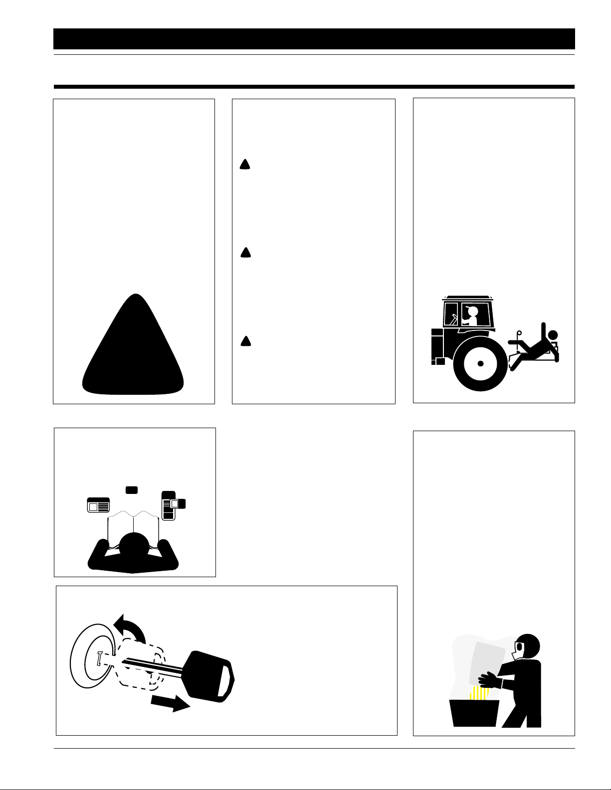
Look for Safety Symbol
The SAFETY ALERT SYMBOL indicates there is a potential hazard to
personal safety involved and extra
safety precaution must be taken.
When you see this symbol, be alert
and carefully read the message that
follows it. In addition to design and
configuration of equipment, hazard
control and accident prevention are
dependent upon the awareness,concern, prudence and proper training of
personnel involved in the operation,
transport, maintenance and storage
of equipment.
!
Be Aware of Signal Words
Signal words designate a degree or
level of hazard seriousness. The signal words are:
!
DANGER!
Indicates an imminently hazardous
situation which, if not avoided, will
result in death or serious injury. This
signal word is limited to the most
extreme situations, typically for
machine components that, for functional purposes, cannot be guarded.
!
WARNING!
Indicates a potentially hazardous situation which, if not avoided, could
result in death or serious injury, and
includes hazards that are exposed
when guards are removed. It may
also be used to alert against unsafe
practices.
!
CAUTION!
Indicates a potentially hazardous situation which, if not avoided, may
result in minor or moderate injury. It
may also be used to alert against
unsafe practices.
Keep Riders
Off Machinery
Riders obstruct the operator’s view.
Riders could be struck by foreign
objects or thrown from machine.
▲ Never allow riders on implement.
▲ Never allow children to operate
equipment.
For Your Protection
▲ Thoroughly read and understand
Safety Decals, page 4. Read all
instructions noted on decals.
OFF
Shutdown and Storage
▲ Lower machine to ground, put
tractor in park, turn off engine,
and remove key.
▲ Detach and store implement in an
area where children normally do
not play. Secure implement with
blocks and supports.
Handle
Chemicals Properly
Agricultural chemicals can be dangerous. Improper use can seriously
injure persons, animals, plants, soil
and property.
▲ Wear protective clothing.
▲ Handle all chemicals with care.
▲ Follow instructions on container
label.
▲ Avoid inhaling smoke from any
type of chemical fire.
▲ Store or dispose of unused chem-
icals as specified by chemical
manufacturer.
4/12/05
705 and 1005 End-Wheel No-Till Drill 150-213M
1
Important Safety Information
Great Plains Mfg., Inc.
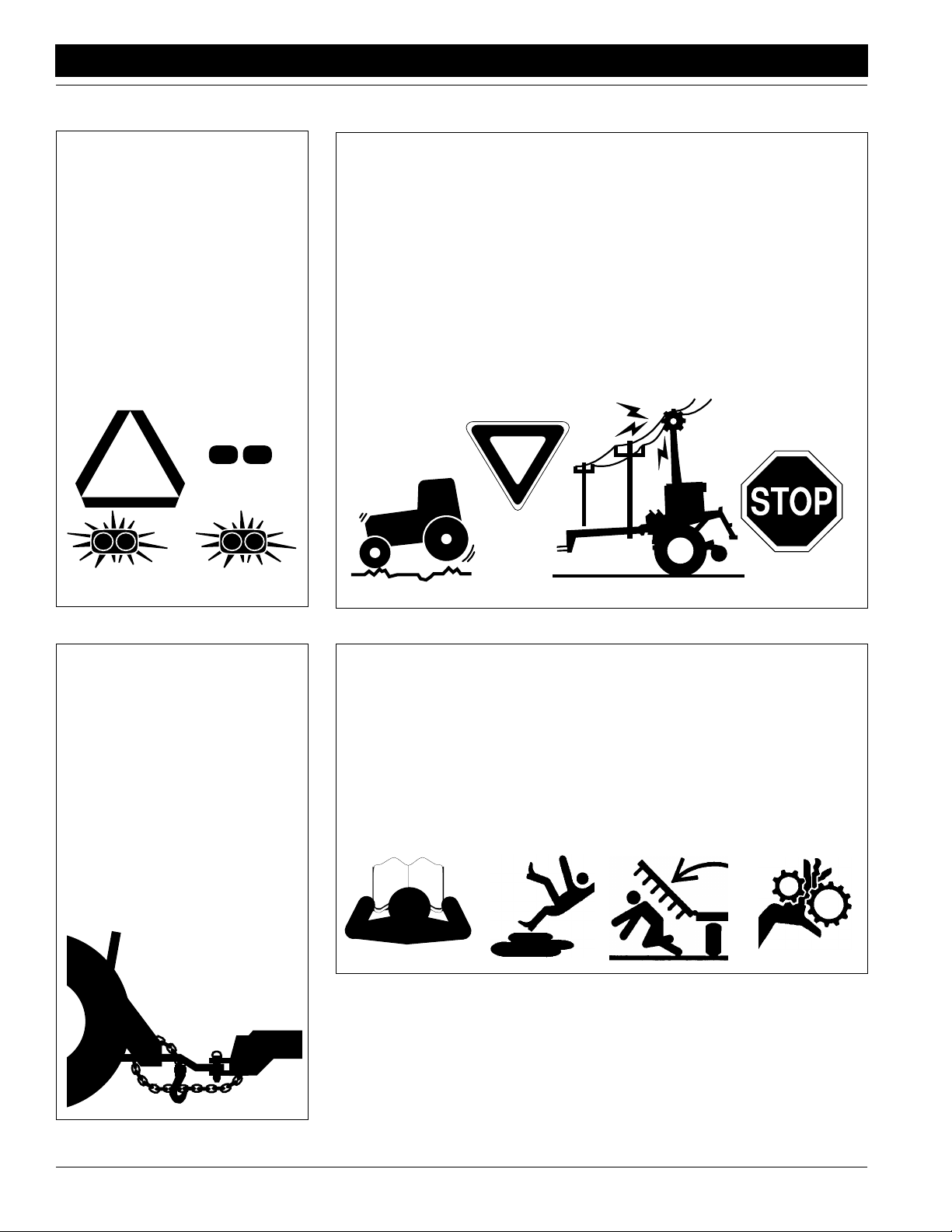
Use Safety
Lights and Devices
Slow-moving tractors, self-propelled
equipment and towed implements
can create a hazard when driven on
public roads. They are difficult to see,
especially at night.
▲ Use flashing warning lights and
turn signals whenever driving on
public roads.
▲ Use lights and devices provided
with implement.
Transport
Machinery Safely
Maximum transport speed for implement is 20 mph. Some rough terrains
require a slower speed. Sudden
braking can cause a towed load to
swerve and upset.
▲ Do not exceed 20 mph. Never
travel at a speed which does not
allow adequate control of steering
and stopping. Reduce speed if
towed load is not equipped with
brakes.
▲ Comply with state and local laws.
▲ Do not tow an implement that,
when fully loaded, weighs more
than 1.5 times the weight of towing vehicle.
Use A Safety Chain
▲ Use a safety chain to help con-
trol drawn machinery should it
separate from tractor drawbar.
▲ Use a chain with a strength rat-
ing equal to or greater than the
gross weight of towed machinery.
▲ Attach chain to tractor drawbar
support or other specified
anchor location. Allow only
enough slack in chain to permit
turning.
▲ Replace chain if any links or end
fittings are broken, stretched or
damaged.
▲ Do not use safety
chain for towing.
Practice Safe Maintenance
▲ Understand procedure before
doing work. Use proper tools and
equipment. Refer to this manual
for additional information.
▲ Work in a clean, dry area.
▲ Lower implement to ground, put
tractor in park, turn off engine,
and remove key before performing
maintenance.
▲ Allow implement to cool completely.
▲ Inspect all parts. Make sure parts
are in good condition and installed
properly.
▲ Remove buildup of grease, oil or
debris.
▲ Remove all tools and unused
parts from implement before operation.
705 and 1005 End-Wheel No-Till Drill 150-213M 4/12/05
2
Great Plains Mfg., Inc.
Important Safety Information
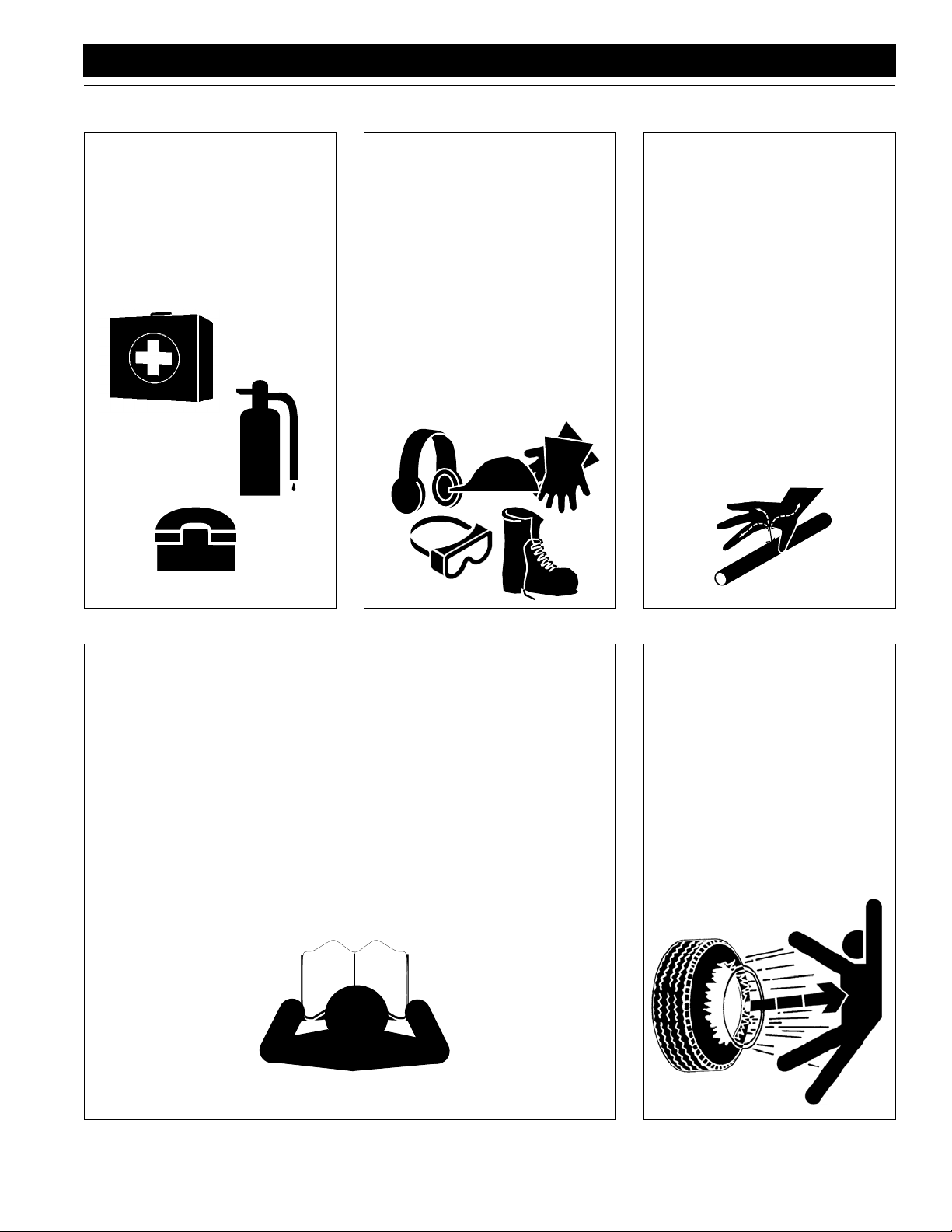
Prepare for Emergencies
▲ Be prepared if a fire starts.
▲ Keep a first aid kit and fire extin-
guisher handy.
▲ Keep emergency numbers for
doctor, ambulance, hospital and
fire department near phone.
911
Wear
Protective Equipment
▲ Wear protective clothing and
equipment.
▲ Wear clothing and equipment
appropriate for the job. Avoid
loose-fitting clothing.
▲ Because prolonged exposure to
loud noise can cause hearing
impairment or hearing loss, wear
suitable hearing protection such
as earmuffs or earplugs.
▲ Because operating equipment
safely requires your full attention,
avoid wearing radio headphones
while operating machinery.
Avoid High
Pressure Fluids Hazard
Escaping fluid under pressure can
penetrate skin, causing serious
injury.
▲ Avoid the hazard by relieving
pressure before disconnecting
hydraulic lines.
▲ Use a piece of paper or card-
board, NOT BODY PARTS, to
check for suspected leaks.
▲ Wear protective gloves and safety
glasses or goggles when working
with hydraulic systems.
▲ If an accident occurs, see a doc-
tor immediately. Any fluid injected
into the skin must be surgically
removed within a few hours or
gangrene may result.
Safety at All Times
Thoroughly read and understand this
manual before operating implement.
Refer to Safety Decals, page 4. Read
all instructions noted on decals.
▲ Be familiar with all implement
functions.
▲ Operate implement from driver’s
seat only.
▲ Do not leave tractor or implement
unattended with engine running.
▲ Do not dismount a moving tractor.
Dismounting a moving tractor could
cause serious injury or death.
▲ Do not stand between the tractor
and implement during hitching.
▲ Keep hands, feet and clothing
away from power-driven parts.
▲ Wear snug-fitting clothing to avoid
entanglement with moving parts.
▲ Watch out for wires, trees, etc.,
when raising implement. Make
sure all persons are clear of working area.
▲ Do not turn tractor too tight, caus-
ing implement to ride up on
wheels.
Tire Safety
Tire changing can be dangerous and
should be performed by trained personnel using correct tools and equipment.
▲ When inflating tires, use a clip-on
chuck and extension hose long
enough to allow you to stand to
one side–not in front of or over tire
assembly. Use a safety cage if
available.
▲ When removing and installing
wheels, use wheel-handling
equipment adequate for weight
involved.
4/12/05
705 and 1005 End-Wheel No-Till Drill 150-213M
3
Important Safety Information
Safety Decals
Your implement comes equipped with all safety decals in place.
They were designed to help you safely operate your implement.
1. Read and follow decal directions.
2. Keep all safety decals clean and legible.
3. Replace all damaged or missing decals. Order new decals
from your Great Plains dealer. Refer to this section for
proper decal placement.
17449
Great Plains Mfg., Inc.
4. When ordering new parts or components, also request corresponding safety decals.
5. To install new decals:
a. Clean the area on which the decal is to be placed.
b. Peel backing from decal. Press firmly on surface,
being careful not to cause air bubbles under decal.
818-003C
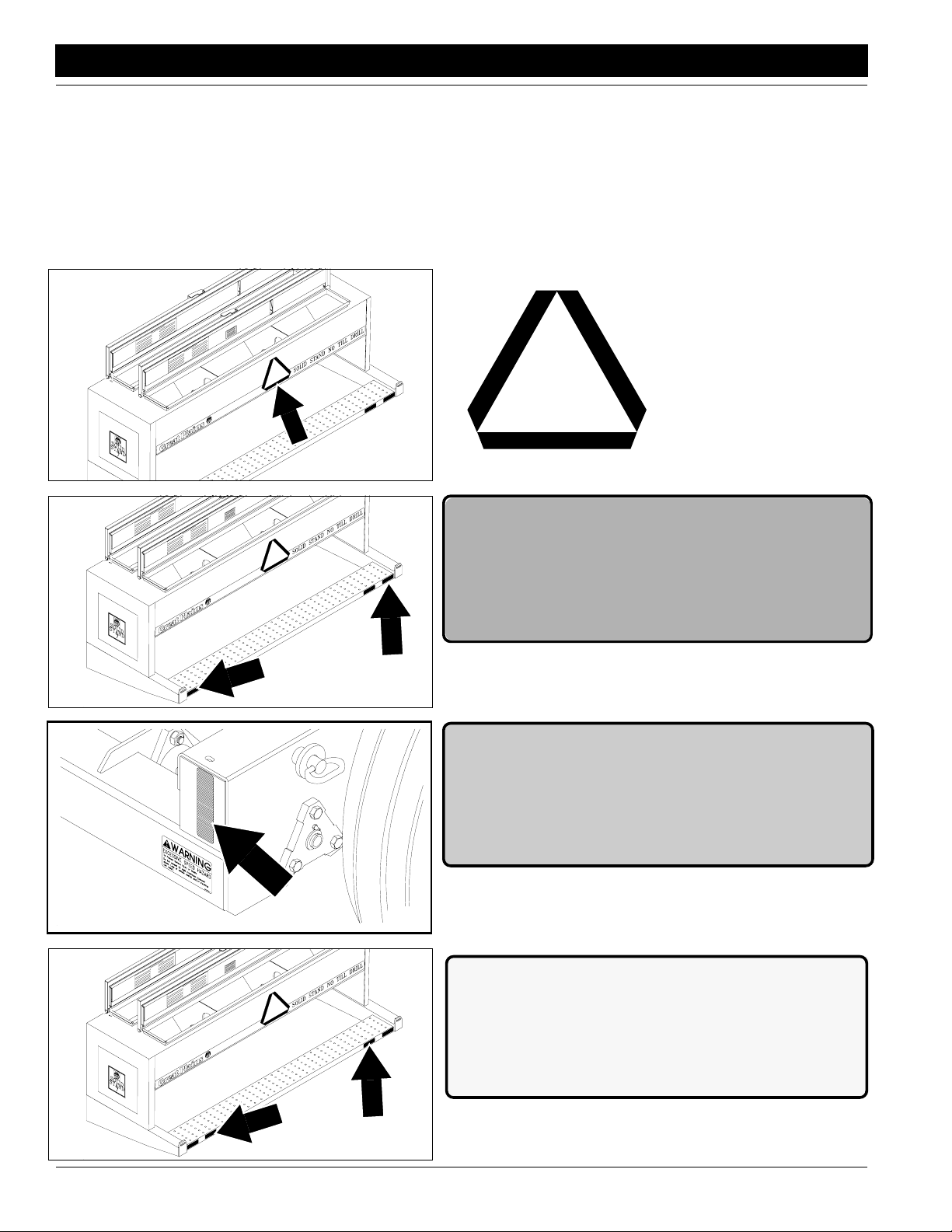
Slow Moving Vehicle Sign
17449
13846
17449
838-266C
Red Reflectors
838-265C
Amber Reflectors
Left and right sides of drill; two decals total
838-267C
Daytime Reflectors
705 and 1005 End-Wheel No-Till Drill 150-213M 4/12/05
4
Great Plains Mfg., Inc.
Important Safety Information
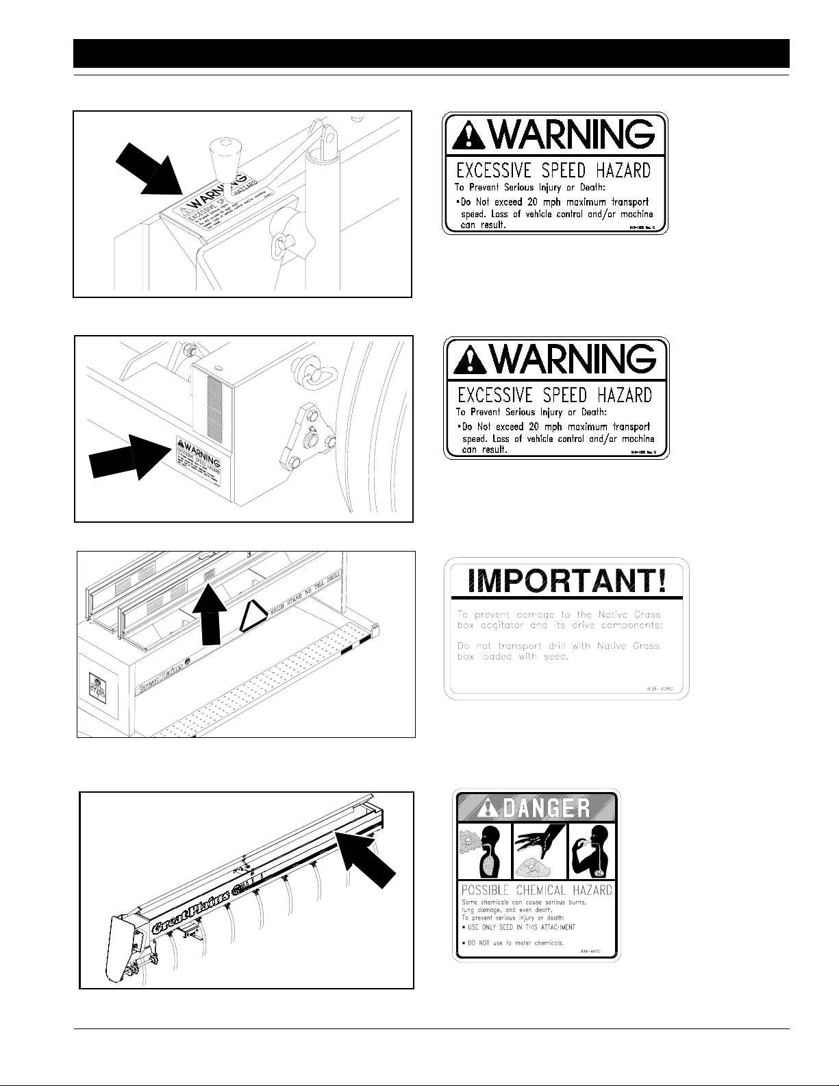
13847
818-188C
Warning 20 MPH Trans
On drill tongue near jack
13846
818-188C
Warning 20 MPH Trans
On front, left-hand side
838-428C
Important to prevent
damage
4/12/05
13734
838-467C
Possible Chemical Hazard
Underside of Lid
705 and 1005 End-Wheel No-Till Drill 150-213M
5
Introduction
Introduction
Great Plains Mfg., Inc.
Great Plains welcomes you to its growing family of new
product owners. This implement has been designed with
care and built by skilled workersusing quality materials.
Proper setup, maintenance and safe operating practices
will help you get years of satisfactory use from this drill.
Description of Unit
The 705 and 1005 are pull-type seedingimplements. The
drills are designed forno-till conditions. Coulters mounted
on the drill frame cut channels for the opener disks. The
opener disks clear away crop residue and open a seed
trench. Seed tubes between the opener disks place seed
in the trench, and press wheels firm soil over the seed.
The press wheels also gauge openerdepth. The705 and
1005 are available in fertilizer or native-grass configurations.
Intended Usage
Use this drill to seed grasses or production-agriculture
crops or to seed over existing grass stands.
Using This Manual
This manual will familiarize you with safety, assembly,
operation, adjustments, troubleshooting and maintenance.Readthis manualand followtherecommendations
to help ensure safe and efficient operation.
Theinformation in this manual iscurrent at printing. Some
parts maychange to assure top performance.
Definitions
The following terms are used throughout this manual.
Right-handand left-hand as used in thismanual are deter-
mined by facing the direction the machinewill travel while
in use unless otherwise stated.
IMPORTANT: A crucial point of information related to
the preceding topic. For safe and correct oper ation,
read and follow directions provided before continuing.
NOTE: Useful information related to the preceding topic.
Owner Assistance
If you need customer service or repair parts, contact a
Great Plains dealer. They have trained personnel, repair
parts and equipment specially designed for Great Plains
products.
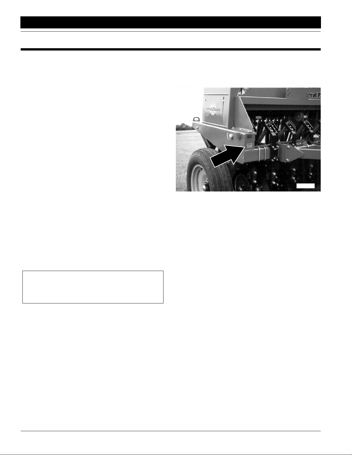
Your machine’sparts were specially designed and should
only be replaced with Great Plains parts. Always use the
serial and model number when ordering parts from your
Great Plains dealer.The serial-number plate is on the drill
frame on the front, right-hand side. See Figure A.
17457
Figure A
Serial Number
Record your drill model and serial number here forquick
reference:
Model Number: _________________________________
Serial Number: _________________________________
Your Great Plains dealer wants youto be satisfied with
your new machine. If you do not understand any part of
this manual or are not satisfied with the service received,
please take the following actions.
1. Discuss the matter with your dealershipservice man-
ager.Make sure they are aware of anyproblems so
they can assist you.
2. If you are still not satisfied, seek out theowner or gen-
eral manager of the dealership.
3. For further assistance write to:
Product Support
Great Plains Mfg. Inc., Service Department
PO Box 5060
Salina, KS 67402-5060
705 and 1005 End-Wheel No-Till Drill 150-213M 4/12/05
6
Great Plains Mfg., Inc.
Section 1 Preparation and Setup
Section 1 Preparation and Setup
This section will helpyou prepareyour tractorand drill for
use. Before going to the field, you must hitch a tractor to
the drill, hook up the hydraulicsand check that the hydraulics have been bled.
Prestart Checklist
1. Read and understand “Important Safety Information” beginning on page 1.
2. Check that all working parts are moving freely, bolts
are tight, and cotter pins are spread.
3. Check that all grease fittings are in place and lubricated.Refer to Lubrication,“Maintenanceand Lubri-
cation,” page 29.
4. Checkthat allsafety decals and reflectors are legible.
Replace if damaged. Refer to SafetyDecals,“Impor-
tant Safety Information,” page 4.
5. Inflate tires and tighten bolts as recommended in the
“Appendix,” page 35.
Hitching Tractor to Drill
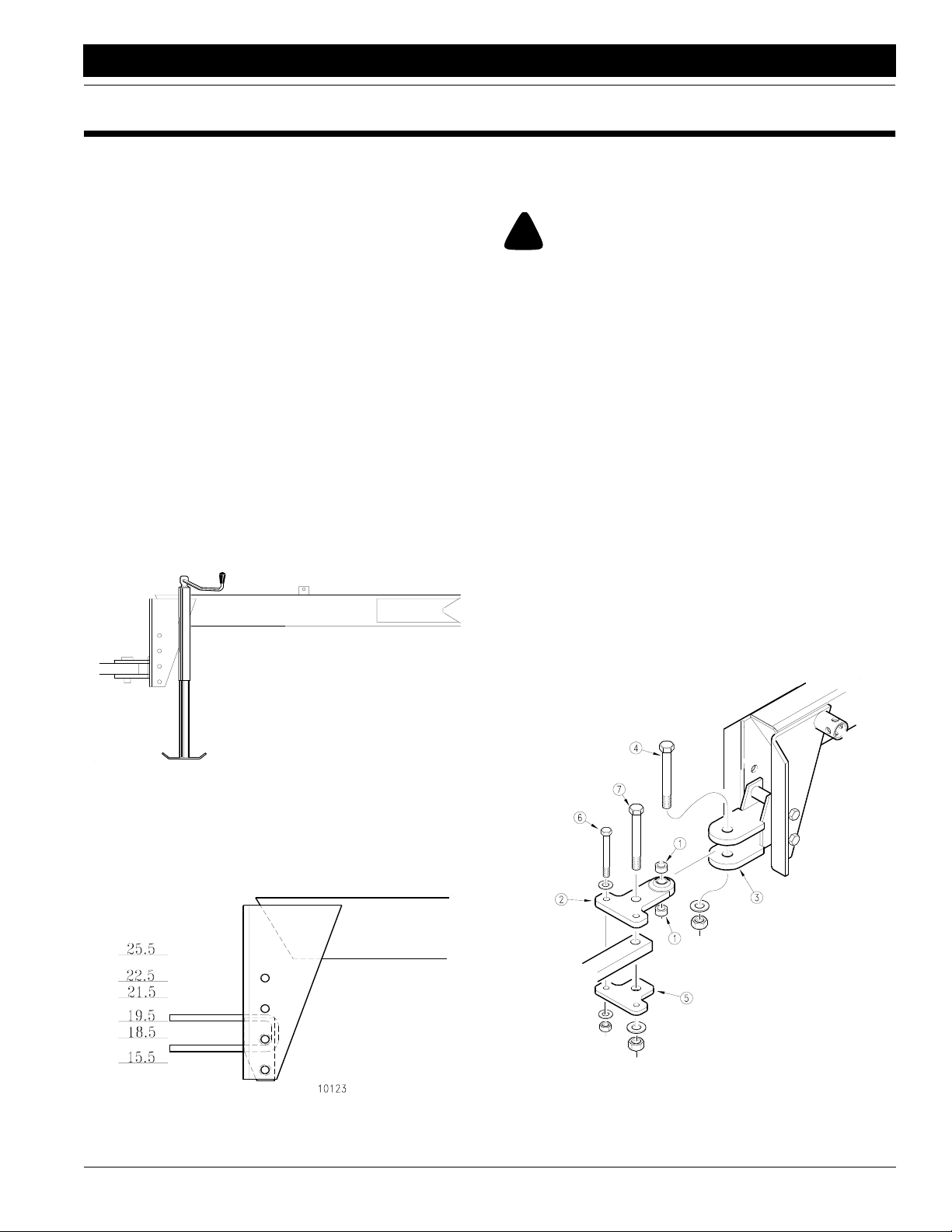
1. With drill lowered in field position and tongue jack
mounted on side of tongue,raise or lower tongue jack
to level drill tongue. See Figure 1-1.
NOTE:When hitchingdrillto a differenttractor,check fora
differencein drawbarheights.If heights aredifferent, readjust hitch height accordingly.
!
DANGER!
You may be severely injured or killed by being crushed between
the tractor and drill. Do not stand or place any part of your
body between drill and moving tractor. Stop tractor engine and
set park brake before assembling ball swivel hitch.
3. When drill hitch matchestractor-drawbar height, hitch
drill to tractor. Refer to Figure 1-3.
a. Place a spacer tube (1) above and below ball
swivel.
b. Bolt ball-swivel plate (2) andspacers to drill hitch
(3) with a 1-by-5-inch bolt (4), flat washer and nylock nut.
c. Back tractor to drill hitch. Using tongue jack, ad-
just drill tongue up or down to center drawbar below ball-swivel plate.
d. Align rear hole in ball-swivel plate with large hole
indrawbar.Place lowerhitch plate (5) underdrawbar.Bolt lowerhitchplate toball-swivelplateusing
two 5/8-inch bolts (6), flat washers and nylock
nuts.
e. Bolt ball-swivel plate through hole in drawbar to
lower hitch plate with 1-by-5 1/2-inch bolt (7), flat
washer and nylock nut.
10150
Figure 1-1
Tongue Level
2. With drill tongue level, adjustdrill hitch on drill tongue
to match your tractor-drawbar height. Refer to Figure
1-2. You can turn the hitch over for a total of six different hitch heights.
10123
Figure 1-2
Hitch Height Adjustment
4/12/05
11549
Figure 1-3
Ball Swivel Hitch
4. Securely attach drill safety chain to an anchoron tractor capable of pulling drill.
705 and 1005 End-Wheel No-Till Drill 150-213M
7
Section 1 Preparation and Setup
Great Plains Mfg., Inc.
5. Store jack on top of tongue as shownin Figure 1-4.
11833
Figure 1-4
Jack in Transport Position
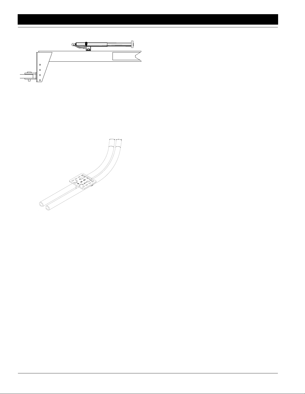
Hydraulic Hose Hookup
Great Plains hydraulic hoses are codedto help you hookup hoses to your tractor outlets. To distinguish hoses on
the same hydraulic circuit, refer to plastic hose holders.
See Figure 1-5. Hose under extended-cylinder symbol
feeds cylinder base ends. Hose under retracted-cylinder
symbol feeds cylinder rod ends.
17641
Figure 1-5
Hydraulic Hose Label
Route lift hoses along tongue and through hose loop on
front of tongue. Connect hoses to tractor remote valve.
Bleeding the Hydraulics
To function properly, the hydraulics must be free of air. If
the hydraulics have not been bled, they will operate with
jerky, unevenmotions. If hydraulics were not bled during
initialdrillsetup or if youreplace a part in hydraulicsystem
during the life of the drill, complete the following procedures.
1. Check hydraulic fluid in tractor reservoir and fill reservoir to proper level.Drill-system capacity is about 1
gallon. Addfluid to system as needed. A low reservoir
levelmaydraw air back into the system, causing jerky
or uneven cylinder movements.
2. Jack up and support front frame tube at a point close
to each end wheel.
3. With frame blocked and supported, unpin cylinders
from drill frame.Turn cylinders upside downand wire
or otherwise safelysupport rod ends of cylinders
higher than base ends.
4. Withtractor engineidling, engagetractor hydraulicsto
extend cylinder rods. When cylinder rods are completely extended, hold remote leveron for one minute.
5. Retract cylinders. Extend cylinders again and hold
remoteleveron for one moreminute. Repeat thisstep
two more times to completely bleed system.
6. Repin cylinders to drill frame with rod ends to wheel
arms.If any airstill is trappedin either cylinder,the cylinder will have a spongy, erratic movementand the
drill will not raise evenly.If necessary, repeat bleeding
process.
7. Refill tractorhydraulic fluidreservoirto its proper level.
705 and 1005 End-Wheel No-Till Drill 150-213M 4/12/05
8
Great Plains Mfg., Inc.
Section 2 Operating Instructions
Section 2 Operating Instructions
This section coversgeneral operating procedures.Experience,machine familiarityand thefollowing informationwill
lead to efficient operation and good working habits.
Always operate farm machinery with safetyin mind.
Prestart Checklist
1. Carefully read “Important Safety Information,”
beginning on page 1.
2. Lubricate the drill as indicated under Lubrication,
“Maintenance and Lubrication,” page 29.
3. Check that drill tires are 9.00 x 24 and are properly
inflated as indicated on Tire Inflation Chart,“Appen-
dix,” page 35.
4. Check all bolts,pins and fasteners. Torque as specified on Torque Values Chart,“Appendix,” page 35.
5. Check the drill for worn or damaged parts. Repair or
replace them beforegoing to the field.
6. Checkhydraulichoses,fittings andcylinders forleaks.
Repair or replace before going to the field.
Field Operation
1. Hitch drill securely to a tractor with sufficient weight
and horsepower. Refer to Tractor Requirements,
“Specifications and Capacities,” page34 and Hitch-
ing Tractor to Drill,“Preparation and Setup,” page 7.
Make sure drill safety chain is secured to tractor.
2. Perform all checks listed on Prestart Checklist,this
page.
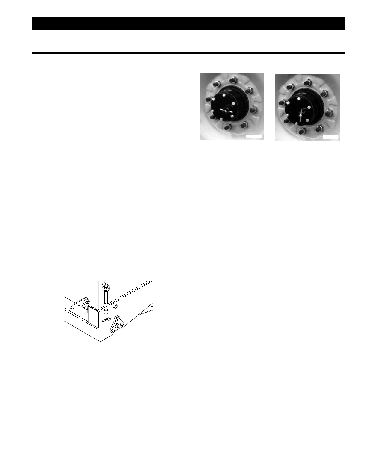
3. Extend lift cylinderscompletely and remove lock pins
from transport position. Place pins in storage. See
Figure 2-1.
10252
Figure 2-1
Lock Pin, Storage Position
4. Engage driveby turninglock-out hub. See Figure2-2.
The lock-out hub is on the left end wheel.
Engaged
17458
Disengaged
Figure 2-2
Lock-Out Hub
17459
5. Calibrate seeding rate as explained under Seed Rate
Adjustment,“Adjustments,” page 14.
6. Load seed box with seed. Use cleaned seed for best
results.
7. Record reading on acremeter, which is mounted on
right-hand end of jackshaft. Subtract this initial reading from later readings to calculate acres drilled.
8. Lower drill and begin seeding.
9. Alwaysraise drill forfield turns. Seedingwill stop automatically as you raise drill.
Opener Operation
Neverback up with openers in ground. If you do, check all
openersto be surenone are clogged.Alwayslift drill outof
ground when turning at ends offield rows and othershortradius turns.
For information on seeding depth and opener adjustments, refer to Seeding Depth and Opener Depth,
“Adjustments,” beginning on page 12.
Native Grass Operation
Native grass drills havea partition dividing the seed and
native-grasscompartments. Seed-compartment capacity
is 1.3 bushels per foot, and native-grasscapacity is 1.2
bushels per foot.
If native grass is not being used, remove chain from
native-grass-drivesprocketto eliminate wear ondrivesystem.
4/12/05
705 and 1005 End-Wheel No-Till Drill 150-213M
9
Section 2 Operating Instructions
Great Plains Mfg., Inc.
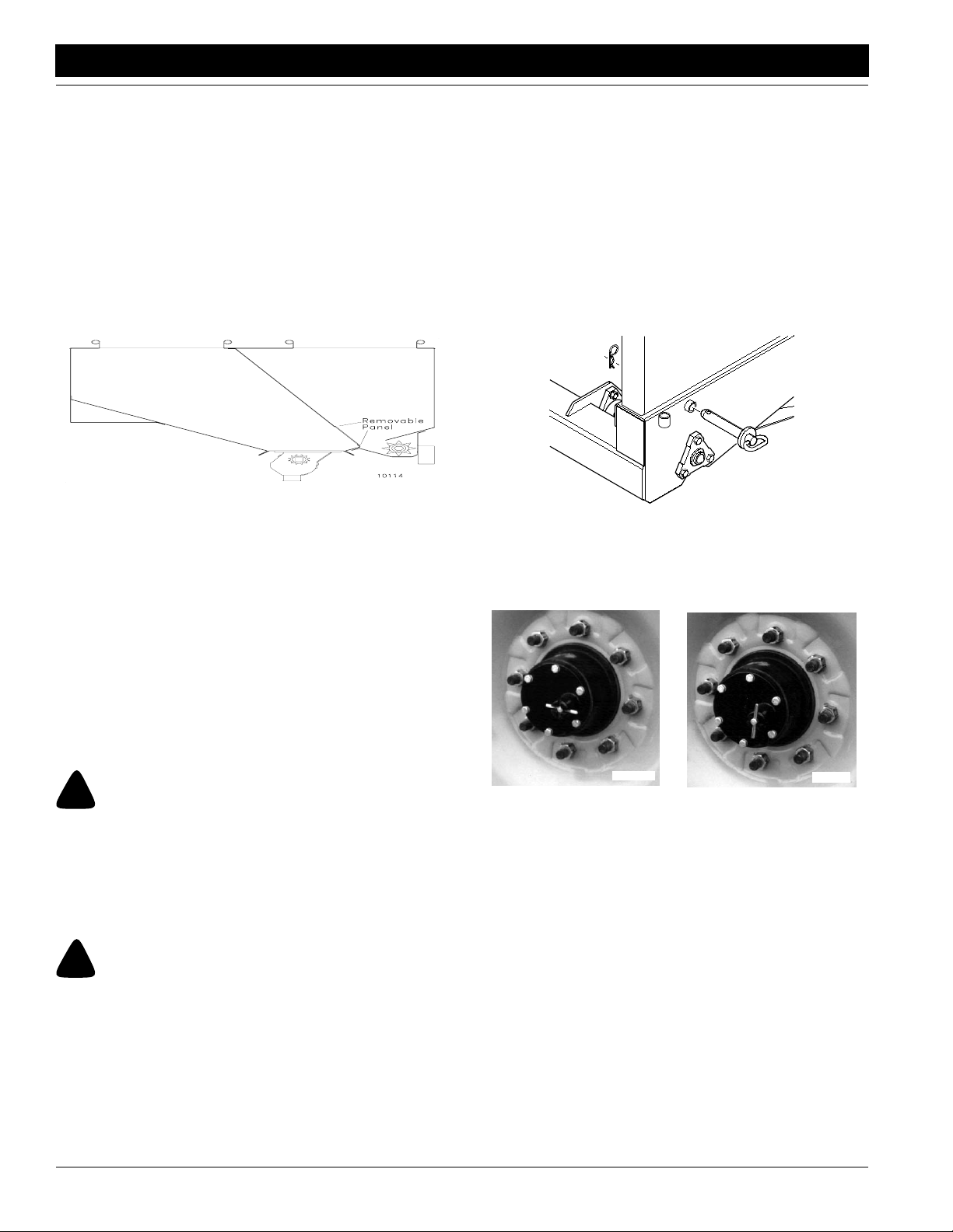
Fertilizer Operation
Fertilizer drills havea partition that divides the box into
seed and fertilizer compartments. See Figure 2-3.
If you wantto use both compartments for seeding grain:
1. Remove the doors in the partition.
2. Set fertilizer-rate-adjustment knob at zero so no seed
escapes through the fertilizer outlets.
3. Remove chain from fertilizer-drive sprocket to eliminate unnecessary wear on fertilizer-drive system.
For information on adjustingthe fertilizer application rate,
refer to Fertilizer Rate,“Adjustments,” page 22.
10114
Divided Panel Panel Removed
Figure 2-3
Fertilizer Partition
Hydraulic Lift System
After a period use, the lift cylinders may get outof time or
phase. When one side of the drill is running too high
because its lift cylinder is either overextended compared
to the other lift cylinder, the cylinders are out of phase.
To rephase cylinders, raise drill until cylinders are completely extended and hold tractor hydraulic lever on for a
fewseconds. Momentarily reversehydraulic leverimmediately after rephasing cylinders to allow cylinders to retract
about 1/2 inch to help maintain a level drill.
Before transporting drill:
1. Check that drill is securely hitched to a sufficient tractor. Refer to Tractor Requirements, “Specifications
andCapacities,” page34 andHitching Tractorto Drill,
“Preparation and Setup,” page 7. Make sure drill
safety chain is secured to tractor.
2. Unload drill box before transporting if at all possible.
Thedrillcan be transported with afull box ofgrain, but
the added weight will increase stopping distanceand
decrease maneuverability.
3. Raise drill. Lock drill up for transport by installing a
lock pin on each side of the drill. See Figure 2-4.
11838
Figure 2-4
Lock Pin, Transport Position
4. Disengage drive byturning the lock-outhub. See Figure 2-5. The lock-out hub is on the left-hand end
wheel.
Transporting
17458
!
WARNING!
Towing the drill at high speeds or with a vehicle that is not
heavy enough can lead to loss of vehicle control. Loss of vehicle
controlcan lead to serious road accidents, injury and death. To
reduce the hazard:
• Do not exceed 20 mph.
• Do not tow adrill that, whenfullyloaded, weighs morethan
1.5 times the weight of the towing vehicle.
!
WARNING!
Failure of the hydraulic cylinders during transport will cause
the drill to drop suddenly, which could lead to serious road accidents, injury or death. To prevent an accident, always install
the lock pins before transporting the drill.
705 and 1005 End-Wheel No-Till Drill 150-213M 4/12/05
10
5. Check that tires are properly inflated. Refer to Tire
6. Comply with all federal, state and local laws when
7. Rememberthat the drill iswider than thetractor.Allow
Engaged
Figure 2-5
Lock-Out Hub
Inflation Chart,“Appendix,” page 35.
travelingon public roads.
safe clearance.
Disengaged
17459
 Loading...