

Page 1
Great Plains Mfg., Inc.
Installation Instructions
705/1005 End Wheel No-Till Drill
Calibration Kit
Used with:
• 705 End Wheel No-Till Drill
• 1005 End Wheel No-Till Drill
General Information
When you see this symbol, the subsequent instructions and
warnings are serious - follow without exception. Your life and
!
!
the lives of others depend on it!
These instructions explain how to install the Calibration Kit Option.
These instructions apply to:
152-289A 705 Calibration Kit
152-290A 1005 Calibration Kit
Manual Update
Refer to the 705/1005 End Wheel No-Till Drill operator’s manual for detailed information on safely
operating, adjusting, troubleshooting and maintaining the calibration kit. Refer to the parts
manual for part identification.
150-213M Operator’s Manual
150-213P Parts Manual
Assembly Instructions
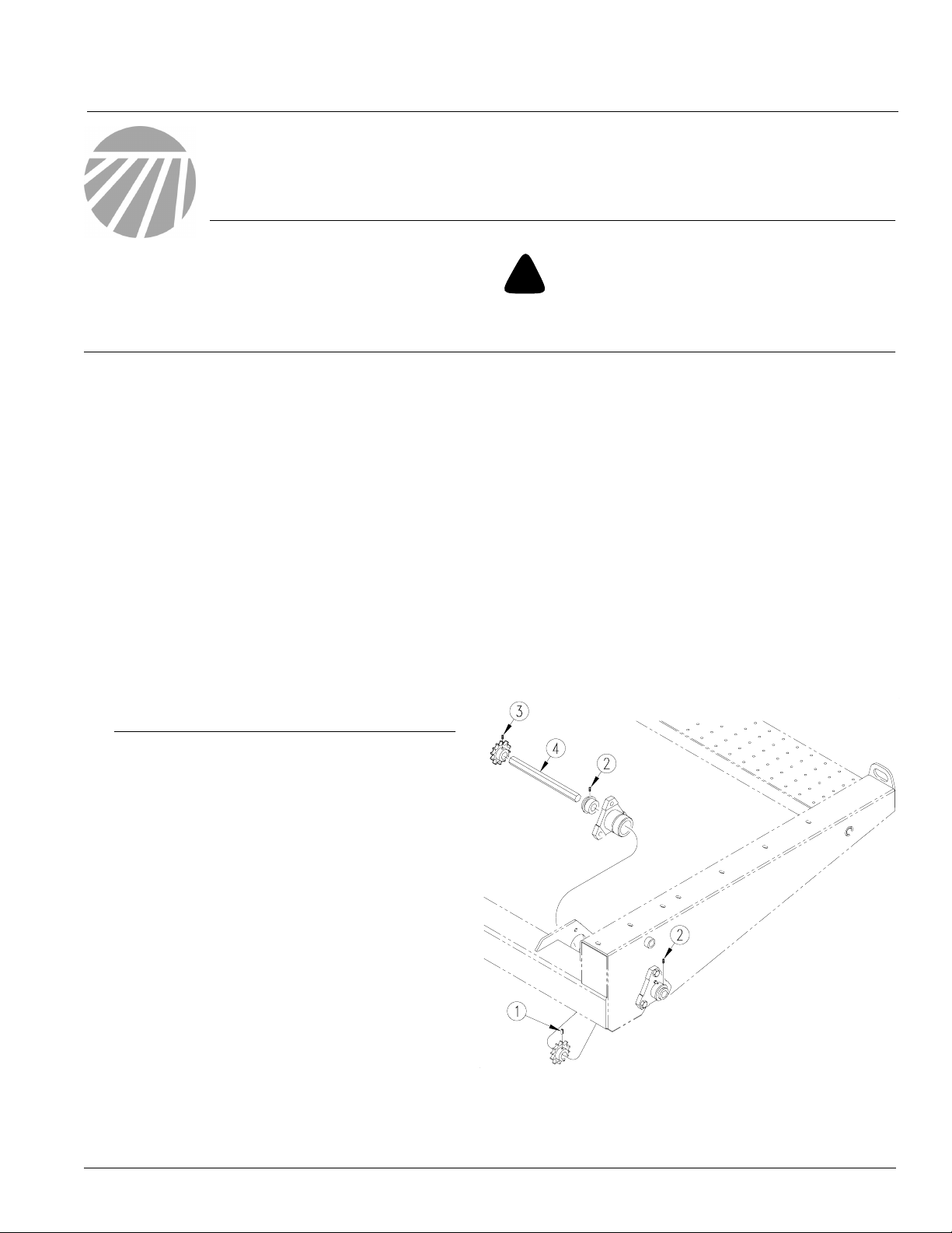
Refer to Figure 1
1. Loosen the drive chain tensioners on both the
drive chains on the left-hand gauge wheel.
Before You Start
Page 3 is a detailed listing of parts included in the
Calibration Kit package. Use this list to inventory
parts received.
Tools Required
• Basic hand tools
• Welder
Definitions
Right-hand and left-hand as used in this manual
are determined by facing the direction the machine will travel while in use unless otherwise
stated.
2. Rotate the left-hand gauge wheel until the roll
pin (1) on the drive sprocket is in a position to
be driven out. Drive out roll pin (1) and keep.
3. Use wire or clamp to hold the sprocket in
place. There is no need to remove drive chain
once the chain has been loosened.
4. Loosen the set screws (2) from both bearings.
5. Loosen the set screw (3) and remove the
sprocket from the end of the jackshaft (4). You
may need to remove the chain if loosening the
tensioner does not allow enough slack for removal of the sprocket.
© Copyright 2003 Printed
3/5/2003
21515
Figure 1
Jackshaft
152-291M
Page 2
Calibration Kit
2
Great Plains Mfg., Inc.
6. Remove the old jackshaft (4) and replace it with
the new one supplied in the kit. Use the new
shaft to push the old shaft out. Position the new
shaft so the end with the 9/32" hole is to the outside of the drill. Make sure the hole for the
sprocket is turned the same direction as the
hole in the sprocket to allow installation of the
sprocket roll pin (1).
7. Align sprocket hole with the hole in the shaft
and reinstall the roll pin (1). Position shaft and
sprocket so the sprocket aligns with the sprockets on the tensioner.
8. Once the sprocket is aligned retighten the set
screws (2) on the bearings to secure shaft in
place.
9. Reinstall the sprocket on the end of the shaft
and tighten the set screw (3). Retighten the
drive chains.
10. Position the crank handle stob on the top side
of the tongue and weld in place. Repaint the
area with green paint (P/N: 821-001C) purchased from your Great Plains dealer.
Refer to Figure 2
9. If rotating gauge wheel jackshaft, disengage the
lockout on the drive wheel and use same number of rotations as for rotating drive wheel.
Check that the three seed cups have plenty of
seed coming into them.
10. Weigh metered seed. Subtract initial weight of
container. Divide by three. Multiply by the number of openers on your drill to determine total
pounds seeded per acre. If this figure is different
than desired, reset sprockets accordingly.
NOTE: You may want to repeat the calibration
procedure if your results vary greatly from the
seed-rate chart.
11. When drilling, check seeding rate by noting
acres drilled, amount of seed added to drill and
seed level in drill box. If you are seeding more or
less than desired, adjust seeding rate slightly to
compensate for field conditions.
Use the following instructions to check seeding
rate.
1. Hydraulically lower drill to planting position to
activate clutch.
2. Check that tires are 9.0 x 24 rib implement and
properly inflated. Refer to "Tire Inflation
Chart," page 35 in the operator’s manual.
3. Jack drive (left) end wheel off ground. Rotate
wheel to see that drive system is working properly and seed cups are free from foreign material.
4. Record weight of an empty container large
enough to hold seed metered for one acre.
5. Place several pounds of seed over three seed
cups on an outside end of the drill box.Pull the
seed tubes off of these three openers.
6. Turn drive end wheel several times to fill seedcups with seed. Turn wheel until seed falls to
the ground from each cup.
7. Place container under the three tubes to gather
metered seed.
Engaged
17458
Figure 2
Drive Wheel Lockout
17459
Disengaged
8. Rotate drive wheel until 1 acre is tallied on
acremeter. This will be 592 rotations on a 7-foot
drill or 422 rotations on a 10-foot drill. You can
also rotate the gauge wheel jackshaft by means
of a wrench or socket or by means of the calibration handle stored on the tongue.
152-291M 9/19/2005
Page 3

Great Plains Mfg., Inc.
152-289A 705 Calibration Kit
Your kit includes:
Qty. Part No. Part Description
1 152-278H EWNT CALIBRATION HANDLE
1 152-291M INSTRUCTIONS, CALIBRATION
1 152-538D 705 NC GW JACKSHAFT
1 152-539D HANDLE STORAGE STOB
1 805-093C PIN COTTERLESS HITCH 1/4 X
Installation Instructions
3
152-290A 1005 Calibration Kit
Your kit includes:
Qty. Part No. Part Description
1 152-278H EWNT CALIBRATION HANDLE
1 152-291M INSTRUCTIONS, CALIBRATION
1 152-506D 100 NC GW JACKSHAFT
1 152-539D HANDLE STORAGE STOB
1 805-093C PIN COTTERLESS HITCH 1/4 X
152-291M9/19/2005
 Loading...