

Great Outdoors Grill Company 4100 Series Assembly And Owner's Manual

the
Great Outdoors
Grill Company
Assembly and
Owner’s Manual
®
Model
4100
Series
Portable
Gas Grill
ASSEMBLER / INSTALLER:
Leave these instructions with the consumer.
CONSUMER / USER:
Read all of these instructions and keep them in a safe place for future reference.
FOR YOUR SAFETY
If you smell gas:
Shut off gas to the appliance.
1
Extinguish any open flame.
2
Open lid.
3
If odor continues, immediately call
4
your gas supplier or fire department.
FOR YOUR SAFETY
Do not store or use gasoline or other
1
flammable vapors and liquids in the
vicinity of this or any other appliance.
2
An unconnected liquid propane
cylinder should not be stored in the
vicinity of this or any other appliance.
FOR YOUR SAFETY: Never leave a grill unattended when in use.

Statement of Commitment
Congratulations and thank you for your purchase
of your new Great Outdoors grill. We are pleased
that you have recognized the value of the design,
function, and quality of components used in this
product. We believe it is among the finest on the
market.
We are committed to producing quality products
that your family will enjoy for years to come. If for
any reason we have failed to meet or exceed your
expectations, please allow us the opportunity to
make it right by calling us toll-free:
888-869-5454
between the hours of 8:00 a.m. and 4:30 p.m.,
central time, Monday through Friday.
We want you to be completely satisfied with your
purchase so you will agree with our motto,
“there’s nothing like...
the great outdoors.”
TM
the
®
Great Outdoors
Grill Company
7980 East American Drive
Joplin, Missouri USA 64804
- A CFM Company -
For more information about our growing family
of barbecue grills, smokers, and outdoor
products, please visit our website at:
www.gogrills.com

Table of Contents
Page Number
Chapter 1 - INSTALLATION
Necessary Information ...........................
Choosing a Safe Location .........................
Portable L.P. Gas Grills ...........................
L.P. Gas Dealer Instructions .......................
Chapter 2 - ASSEMBLY INSTRUCTIONS
Step 1 ( Identifying Parts ) .........................
Step 2 ( Assemble Pillar to Grill Bottom ) .............
Step 3 ( Attach Base ) ............................
Step 4 ( Side Tables ) ............................
Step 5 ( Assemble Grill Lid ) .......................
Step 6 ( Internal Parts ) ...........................
Installing an L.P. Gas Cylinder .....................
Connecting an L.P. Gas Cylinder . . . ................
4
4
4
5-7
8
9
10
11-12
13
14
15-16
17-18
19
20
Chapter 3 - USE and CARE
Leak Testing ...................................
Lighting Instructions .............................
Using Your Grill .................................
Caring for Your Gas Grill ..........................
Cleaning and Maintenance ........................
Replacement Parts ..............................
Troubleshooting Guide and FAQ’s ..................
Chapter 4 - OUTDOOR COOKING / RECIPES
Recipes .......................................
Warranty ......................................
21
22
23-24
25
26
27
28-29
31-33
34
34-37
38
3
Model 4100 Series Gas Grill
Installation 1Chapter
Necessary Information to
Safely Use a Gas Grill
The gas fuel used by this product is
highly flammable and must be used in
a responsible and cautious manner.
It is your responsibility to assemble,
operate, and maintain your gas
barbecue grill properly.
·
Operating this or any gas-fired appliance
in an enclosed area can produce a build-up
of carbon-monoxide, which could result in
injury or death.
2. Installation must conform with local
codes
either the National Fuel Gas Code, ANSI
Z223.1, NFPA 54 (USA), or CAN/CGA-B
149.2, Propane Installation Code (Canada)
and CAN/CGA-B 149.1 Natural Gas
Installation Code.
To check local codes, contact your local gas
dealer or gas company listed in the Yellow
Pages for recommended installation
procedures and regulations.
3. This appliance is not intended to be
installed in or on a recreational vehicle
and/or boat.
or, in the absence of local codes, with
If these instructions are ignored, there
is a possibility of a hazardous fire or
explosion which could result in proper-
ty damage, physical injury or death.
Choosing a Safe Location
for a Gas Barbecue Grill
1. The gas barbecue grill may only be used
for cooking out-of-doors.
· Do not operate this barbecue in garages,
breeze ways, sheds or any enclosed area.
4. Keep the barbecue grill at least 24
inches (61 cm) away from any combustible
construction.
·
Do not use a grill under a ceiling or cover
where the heat or flame could cause
damage.
·
Choose a level surface where the grill is
not facing directly into the wind.
·
Avoid moving the grill during use.
5. The grill area must be clear and free from
combustible materials, gasoline, and any
other flammable liquids or vapors.
·
Do not use lighter fluid or charcoal
briquettes in a gas grill. The flow of
combustion and ventilation air is not to be
obstructed. The ventilation openings of the
cylinder enclosure must be kept free and
clear from other debris. Do not store grill
covers or other items in the cylinder area.
4
9. Make sure that the heat shield and drip
The L.P. Fuel Supply System
pan are in place under the grill bottom.
Heat and hot drippings from cooking food
·
could damage the fuel supply system.
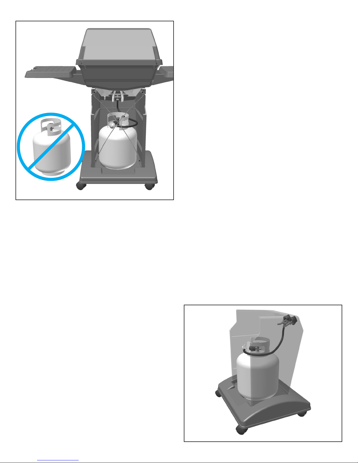
6. Do Not store a spare L.P. gas cylinder
under or near this appliance.
Do not store an L.P. cylinder in a building,
garage or any other enclosed area. Instead,
store the cylinder outdoors in a well
ventilated area, away from people and out of
the reach of children.
7. NOT FOR USE BY CHILDREN.
Place your barbecue grill in a location
·
away from children and pets.
Do not leave grill unattended when in use.
·
IMPORTANT:
unattended when in use.
NEVER leave a grill
Portable L.P. Gas
Barbecue Grills
WARNING:
appliance designed for L.P. gas. Use only
liquid propane (L.P.) gas in an appliance
designed for L.P. gas.
L.P. Gas
Liquid Propane (abbreviated L.P.) gas is
stored under high pressure inside a cylinder
and will vaporize when released. It is
important that there are no leaky connections
on the grill fuel supply system. Refer to the
Leak Testing section of this manual.
The L.P. Fuel Supply System
An L.P. gas grill requires a fuel delivery
system made up of a L.P. gas supply
cylinder, a fuel regulator with hose and a
gas-control valve.
Do not use natural gas in an
8. The outside of the barbecue grill will
become hot during use.
To avoid burns, do not touch any hot grill
·
surface. If necessary, use a protective glove
when operating control knobs, tank shut-off
valve, or lid handle.
Do not place combustible material, such
·
as cloth or plastic, on grill surface during
use.
·
Do not lean on side tables or place more
than 15 pounds of weight on a side table.
The L.P. Fuel Supply System
5
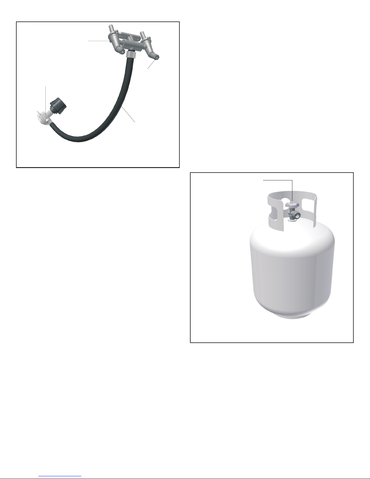
Dual Burner
Fuel-Control Valve
4. The pressure regulator and hose
assembly provided is factory set at an outlet
pressure of 11 inches water column (.4 lb.
per sq. Inch).
Type 1 Fuel
Regulator
Fuel Supply
Valve
Orifice
Hose
The L.P. Fuel Supply System
(the fuel regulator and hose)
FUEL REGULATOR AND HOSE
The fuel regulator supplied is equipped with
a Type 1 coupling nut. Do not attempt to
connect to any other L.P. cylinder not
equipped with a mating Type 1 cylinder
valve. This grill is not to be used with any
other cylinder connection device.
The fuel regulator and hose assembly with
the Type 1 fitting supplied must be used with
the appliance. Do not use a hose and
regulator assembly other than the one
supplied with the grill or a manufacturer’s
replacement fuel pressure regulator
assembly.
The Type 1 connection system has the
following features:
1. The system will not allow gas to flow until
a positive connection has been made.
2. The system has a thermal element that
will shut off the flow of gas between 240°F
and 300°F.
3. The system has a flow-limiting device
which, when activated, will limit the flow of
gas to 10 cubic feet per hour.
WARNING:
Any attempt to adjust the
regulator is dangerous and could create a
situation causing personal injury or property
damage. Consult your L.P. gas dealer if you
think the regulator is not working properly.
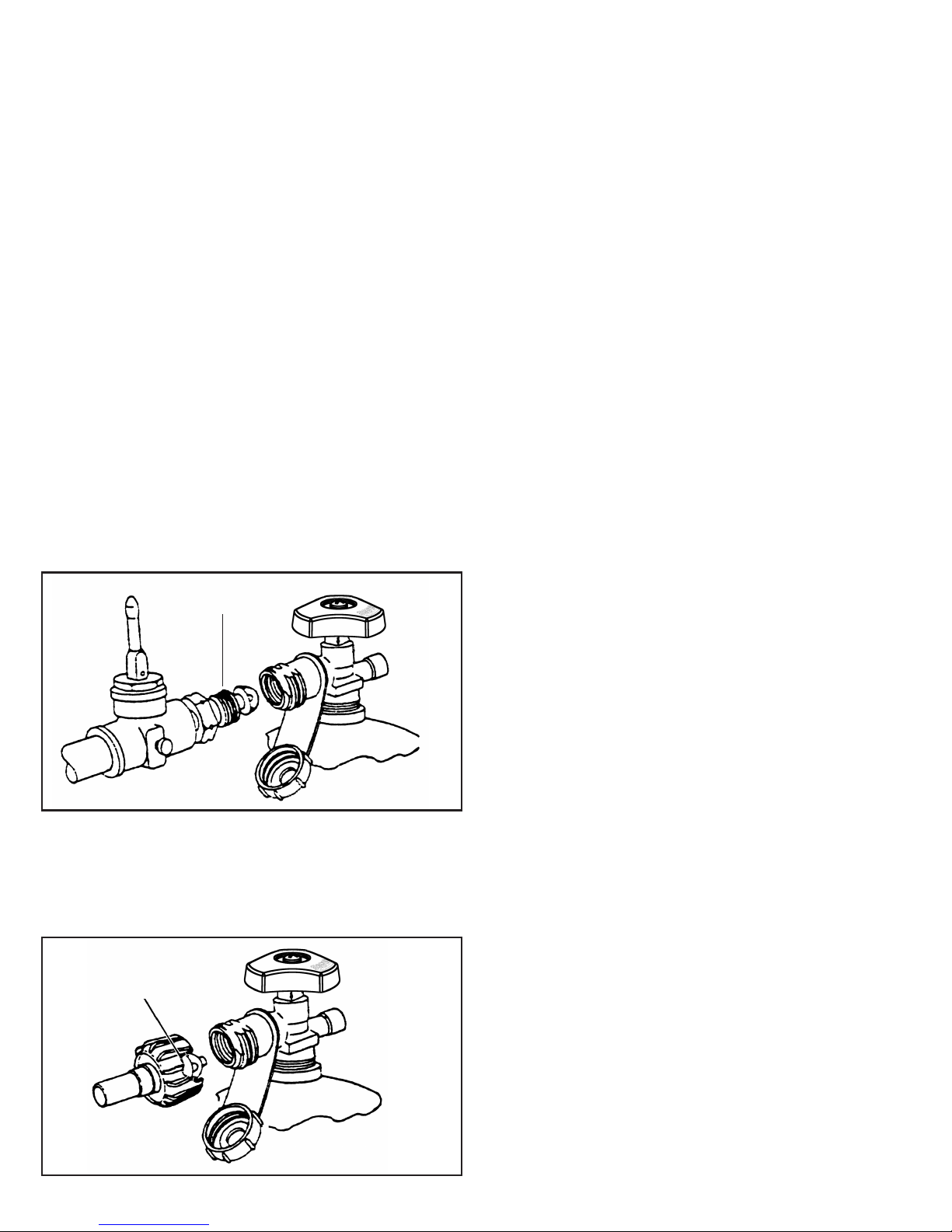
L.P. GAS SUPPLY CYLINDER
L.P. Cylinders can be obtained at the store
where you purchased your grill or from an
authorized L.P. gas dealer.
Cylinder Control
Valve
L.P. Gas
Cylinder
NOTE: 4100W
Model grills
DO NOT
include an L.P.
gas cylinder
The L.P. Fuel Supply System
(L.P. gas cylinder)
L.P. GAS CYLINDER SPECIFICATIONS
Any L.P. gas-supply cylinder used with this
grill must be approximately 12 inches
diameter and 18 inches high.
The maximum
fuel capacity must be 20 pounds of propane.
Full-cylinder weight should be approximately
38 pounds (43.7 lbs. Nominal water
capacity).
The L.P. cylinder must have a shut-off valve
6
terminating in a Type 1 L.P. gas-cylinder-
The heat shield, gaskets, collar assembly
valve outlet. A Type 1 compatible cylinder
with a Type 1 cylinder valve has a positive
seating connection that does not permit gas
flow until a positive seal has been obtained.
The cylinder must be arranged for vapor
withdrawal. It must also include a collar to
protect the cylinder valve. A safety-relief
device having direct communication with the
vapor space of cylinder must be provided.
This will expel high-pressure gas if the
cylinder is overfilled or overheated.
All L.P. gas cylinders used with this
appliance shall be constructed and marked
in accordance with the specifications for L.P.
gas cylinders of the U.S. Department of
Transportation (DOT) or the National
Standard of Canada, CAN/CSA-B339,
Cylinders, Spheres and Tubes for
Transportation of Dangerous Goods; and
Commission, as applicable; and shall be
provided with a listed overfilling-prevention
device. Read labels on the L.P. gas-supply
cylinder.
percent full.
c.) If the information in (a.) and (b.) Is not
followed exactly, a fire causing serious injury
or death may occur.
TRANSPORTING A FULL CYLINDER
WARNING:
Handle a full cylinder with care.
Gas is under high pressure.
You should transport only one cylinder at a
time. Transport the cylinder in an upright and
secure manner with the control valve turned
off and the POL plug in place.
Do not transport a cylinder in the passenger
compartment of a vehicle.
Do not leave cylinder in direct sunlight or in
a high-heat area such as a closed car trunk.
High-heat areas could cause the relief valve
to vent gas.
Use a cylinder cap on the cylinder-valve
outlet during transport and when the cylinder
is not connected to the grill. Keep cylinder
valve closed when not in use.
DANGER:
Do not insert any foreign objects
into the valve outlet. You may damage the
back check, A damaged back check can
cause a leak, which could result in explosion,
fire, severe personal injury or death.
Allow only a qualified L.P. gas dealer to
fill or repair an L.P. gas-supply cylinder.
Inform the gas dealer if it is a new or used
cylinder to be filled. Caution the gas dealer
not to overfill the fuel cylinder.
After filling, have the gas dealer check for
leaks and that the relief valve remains free to
function.
Have the gas dealer weigh the cylinder
after filling to ensure that the cylinder is not
overfilled.
DANGER:
a.) Do not store a spare L.P. gas cylinder
under or near this appliance.
b.) Never fill the gas cylinder beyond 80
HEAT SHIELD, GASKETS AND COLLAR
WARNING:
Do not remove the heat shield,
gaskets or collar assembly from the grill
bottom.
Operating this grill without the heat shield,
gaskets and collar assembly attached to the
grill bottom would result in a hazardous
situation which could cause serious property
damage and possible physical injury.
The heat shield, gaskets, collar assembly
7
Take These Instructions to the L.P. Gas Dealer
When using a cylinder exchange, be sure the
exchanged cylinder is a Type 1 cylinder; a 510
POL cylinder will not fit a Type 1 regulator.
FILLING AND PURGING
TYPE 1 L.P. GAS CYLINDERS
DANGER:
Purging and filling of L.P. gas
cylinders must be performed by personnel who
have been thoroughly trained in accepted L.P.
gas industry procedures. Failure to follow this
instruction may result in explosion, fire, severe
personal injury or death.
IMPORTANT:
Purge new cylinders before
filling. This tank is easily filled with a standard
CGA 510 POL filling connection.
The L.P. gas cylinder has a Type 1 cylinder
valve with a back-check module in its outlet
that will not permit gas to flow until an
evacuation device is installed. To purge the
L.P. gas cylinder, the back-check module must
be opened with an evacuation device.
PURGING AND EVACUATION DEVICES
FOR L.P. GAS CYLINDER WITH TYPE 1
CYLINDER VALVES
A. Hose-end valve with a bleed port: Purging
can be accomplished using a hose-end valve
containing a bleed port, which also allows for
evacuation without the use of an adapter.
B. Hose-end valve without a bleed port:
When a hose-end valve does not have a bleed
port, a separate device must be used for
evacuation.
CGA-510 POL
Example A
Filling a Type 1 Cylinder Valve
Example A: shows a CGA-510 POL fitting.
Example B: shows using a Type 1 POL fitting.
Type 1
(cut away to see fitting)
C. Purging using a Type 1 connection: L.P.
gas cylinder evacuation can be accomplished
during each purging by using a Type 1
connection. The Type 1 valve outlet has 15/16” external ACME right-hand thread that will
accept this connection.
CAUTION:
After purging or filling an L.P. gas
cylinder, do not insert a POL plug into the
valve outlet. Insertion of this plug will prevent
the back-check from closing. Use ONLY the
provided cap and strap attached to the outlet.
Close the cylinder valve knob before returning
the cylinder to the customer.
For proper purging procedures in the USA,
refer to: Safety Bulletin NPGA # 133, “Purging
L.P. Gas Cylinders,” and Safety Bulletin NPGA
#130, “Recommended Procedures for Filling
Cylinders.”
Example B
DANGER:
Do not fill an L.P. gas cylinder
beyond 80% full. If this information is not
followed exactly, a fire causing serious injury
or death may occur.
8
Model 4100 Series Gas Grill
Assembly Instructions 2Chapter
Getting Started
1. Please follow the steps in the order that
they are presented.
2. Assemble the grill where you plan to use
it.
3. You may want to place an old towel or
cloth at the assembly site to prevent nuts
and bolts from becoming lost.
4. Have a friend help. An assistant can
make the assembly easier by holding the
parts in place while you fasten the nuts and
bolts.
5. To be ready to barbecue immediately,
have the L.P. gas cylinder filled by an
authorized L.P. dealer or cylinder exchange
center.
3/8
Unpacking the Grill Parts
7/16
1. Remove and set aside all inner boxes
and parts from the master carton.
2. Remove and set aside all wrapping
paper and additional packaging from the
parts.
3. Do not destroy carton or packing until
your grill is completely assembled and
operating to your satisfaction.
Note: You may notice during assembly that hardware
bag “B” is used before hardware bag “A”. The
assembly procedure has been improved from the
original sequence to make assembly easier. However,
hardware packaging has not been changed.
Tools needed to assemble grill:
·
3/8” open-end wrench*
·
flat-head screwdriver
·
7/16” open-end wrench*
A socket set or an adjustable wrench may be used
*
in place of the open-end wrenches.
9
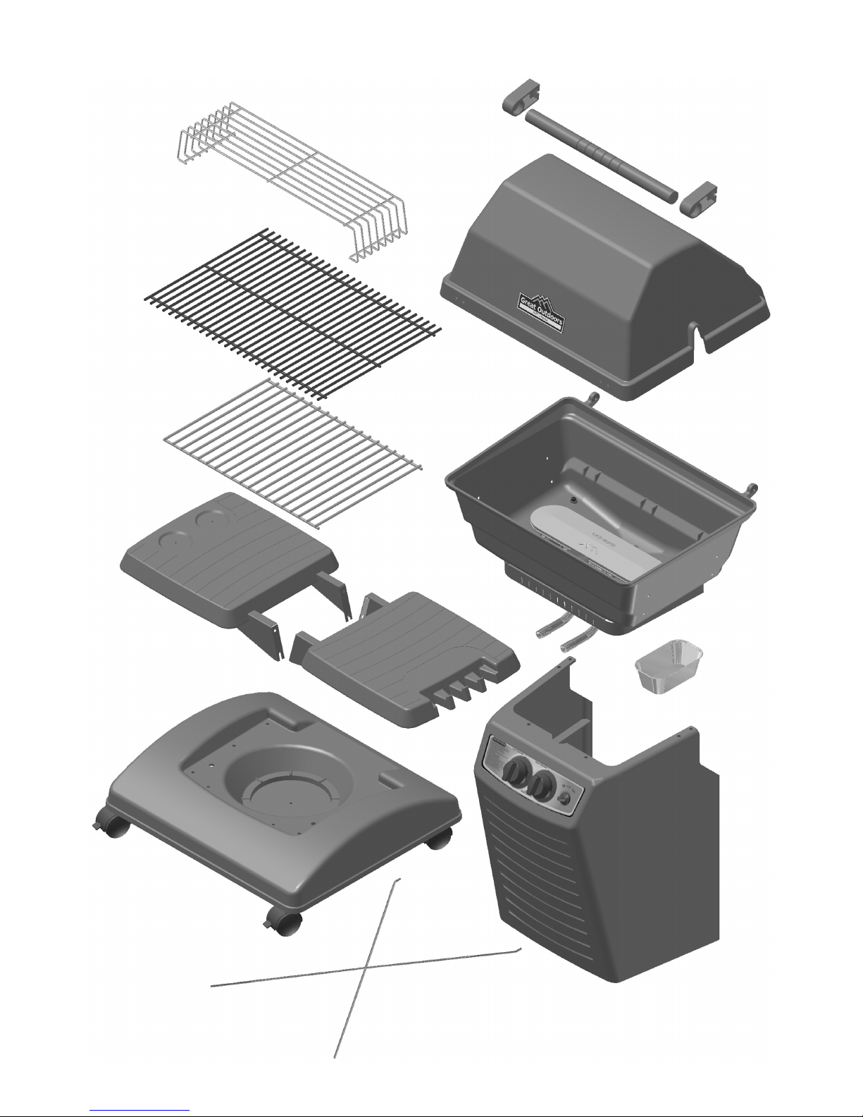
Assembly Step 1 - Identifying the Grill Parts
Locate these parts:
warming rack (1)
cooking grid (1)
rock grate (1)
handle (1)
handle
standoffs (2)
grill lid (1)
grill bottom
assembly (1)
(burner assembly, heat
shield, collar gasket
& collar installed)
left side
table (1)
right side
table (1)
base (1)
(2 locking casters and
2 non-locking casters
installed)
grease
pan (1)
pillar (1)
(knobs, ignitor,
valve, hose
with regulator
installed)
Not Pictured:
ceramic briquettes (1 pkg)
master hardware bag (1)
(consisting of 1 each of A,B,C,D bags)
X-brace
wire (1)
10
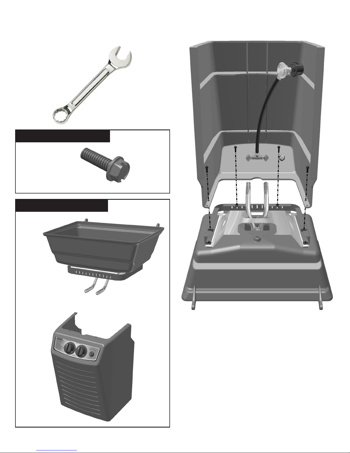
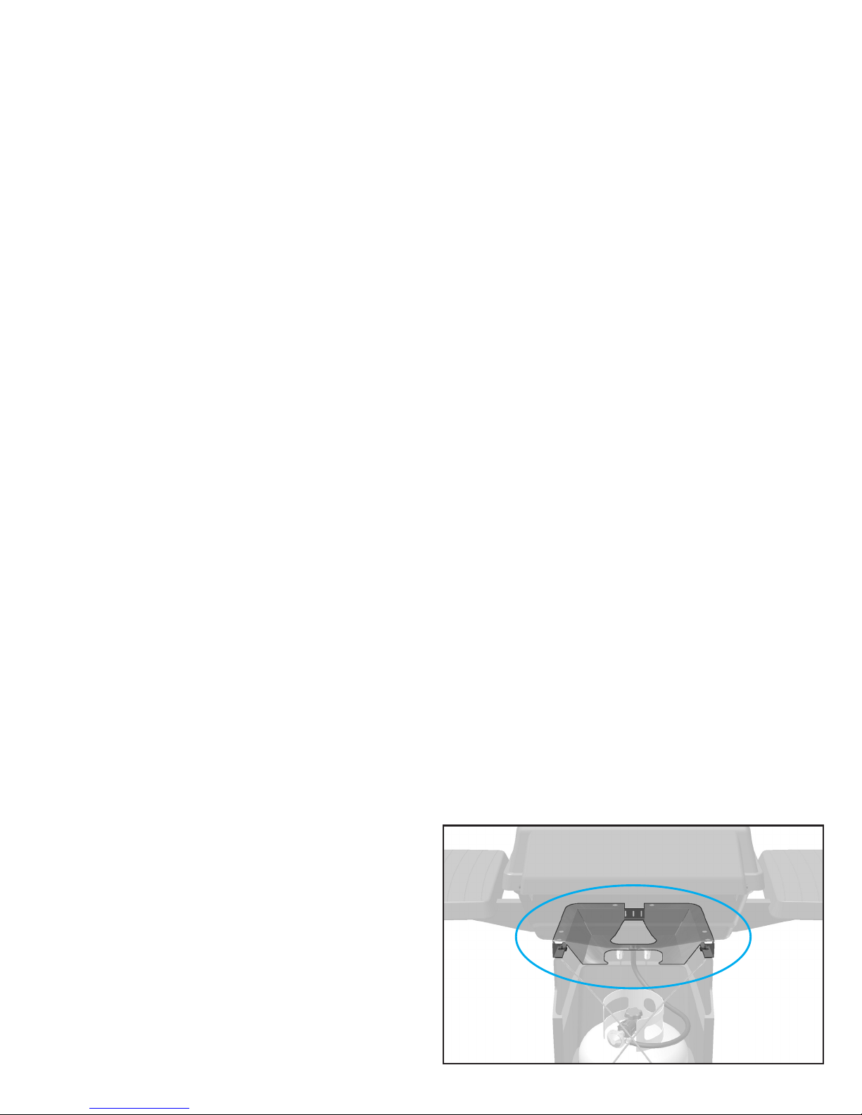
Assembly Step 2 - Attach Pillar to Grill Bottom
back of pillar, upside down
Tools Needed:
3/8”
wrench
USE HARDWARE BAG B :
1/4-20 x 3/4”
bolt (4)
LOCATE THESE PARTS:
grill bottom
assembly (1)
pillar
assembly (1)
back of grill bottom, upside down
HINT: For the first portion of the assembly you will be
assembling the grill bottom, pillar and base upside
down.
Position the grill bottom casting upside down so
1.
that the heat collar assembly is upward.
11
Working from the back (open) side of the pillar,
2.
set the pillar upside down onto the collar
assembly.
3.
Locate the holes in the pillar bottom and align
with holes in collar.
Assembly Step 2 - Continued
IMPORTANT: Make sure the control valve
4.
ends are seated inside the burner tubes as
shown.
attached to the pillar; the burner tubes are
attached and extend through the grill
bottom.)
Insert the four bolts through the pillar holes
5.
and thread them into the speed nuts on the
collar. Use a wrench to secure the bolts,
being careful not to over-tighten.
(The control valve ends are
Burner Tube
Control Valve
!
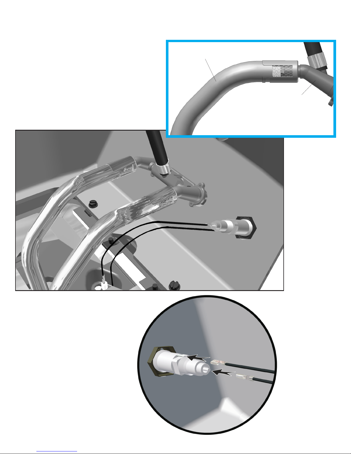
Locate the black igniter wires
6.
beneath the grill bottom. Press
the metal contact of the loose
end of the wires onto the
metal pins of the igniter unit.
12
 Loading...