


Manual No. 692P
Revision 9-898
MODEL 692P
TWO-WIRE
pH TRANSMITTER
-1-
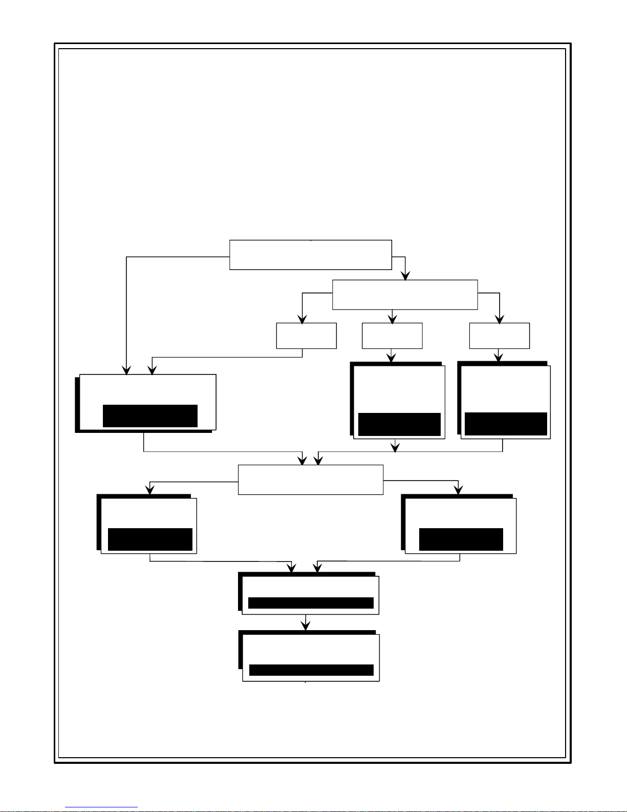
INSTRUMENT SETUP GUIDE
This manual contains detailed instructions for all operating aspects of this instrument.
Read Part One for a general description of the Model 692P. Part Two explains how to
install and wire the instrument. To familiarize yourself with the basic operation of the
692P, read Part Three, Sections 1, 2 and 3. For instrument startup, perform the setup
steps in Section 4. The following guide shows you the appropriate Section 5 and 6 subsections to use for temperature and pH calibration when using a GLI 5-wire Differential
Technique sensor or a conventional pH combination electrode.
5-Wire Sensor
Single Or Two-Point
Temperatue Calibration*
Section 5.2 or 5.3
(start on pg. 30)
"Two-key"
Two-Point Or
Table Method
Section 6.4 or 6.5
(start on pg. 34)
Which type of sensor are you
using with this transmitter?
300 Ohm
Thermistor
*
Temperature calibration is
only necessary w hen
extremely accurate
measurement is required.
Which pH calibration method
do you intend to use?
Combination Electrode
What type of temperature
compensation is used?
1000 Ohm
RTD
Two-Point
Temperature
Calibration
Section 5.3
(start on pg. 30)
Conventional
Single Or Two-Point
Method
Section 6.2 or 6.3
(start on pg. 32)
Fixed
Resistor
Single-Point
Temperature
Calibration
Section 5.2
(start on pg. 30)
Rev. 9-898 Model 692P
Output Setup
Section 7 (start on pg. 40)
Using Security
Lock Feature
Section 8 (start on pg. 42)

Model 692P Rev. 9-898
-2-

-3-
TABLE OF CONTENTS
PART ONE - INTRODUCTION
SECTION 1 GENERAL INFORMATION
1.1 Instrument Capability:
Input Versatility ........................................................7
Display Readouts.....................................................7
Operator Interface....................................................7
Output Flexibility ...................................................... 7
Operator Safety........................................................7
1.2 Battery Backup..........................................................7-8
1.3 Product Identification ...................................................8
SECTION 2 SPECIFICATIONS................................................................9
PART TWO - INSTALLATION
SECTION 1 UNPACKING......................................................................10
SECTION 2 MECHANICAL REQUIREMENTS
2.1 Location......................................................................10
2.2 Mounting ...............................................................10-12
2.3 Plugging Conduit Holes .............................................12
SECTION 3 ELECTRICAL CONNECTIONS
3.1 GLI 5-Wire Differential Technique Sensor.................12
3.2 Conventional Combination Electrode:
Direct Hookup (distances less than 10 feet) .....13-14
Indirect Hookup with Model 714 Preamp
(distances more than 10 feet) ............................15
3.3 Power Supply............................................................. 15
3.4 Analog Output.......................................................15-17
3.5 Hazardous Area Wiring.........................................17-18
PART THREE - OPERATION
SECTION 1 OPERATING CONTROLS
1.1 Keypad Switches...................................................19-22
` 1.2 Slide Switches.......................................................22-23
1.3 Program Jumper......................................................... 24
1.4 Status Indicators ........................................................ 25
SECTION 2 MEASURED VARIABLES.................................................. 25
Rev. 9-898 Model 692P

-4-
TABLE OF CONTENTS (continued)
SECTION 3 SETUP VARIABLES
3.1 Calling Up Setup Variables........................................ 26
3.2 Entering Values..........................................................26
3.3 Setup Variables Call-Up Chart and
Table of Descriptions........................................26-29
SECTION 4 INSTRUMENT STARTUP
4.1 Checking Battery Backup Jumper.............................. 29
4.2 Setting Sensor Input Type:
GLI 5-Wire Differential Technique Sensor.............29
Conventional Combination Electrode................29-30
4.3 Selecting Temperature Display Units (°C or °F) ........30
4.4 Understanding Calibration ......................................... 30
4.5 Selecting Default State for Out-of-Range Condition..30
SECTION 5 TEMPERATURE CALIBRATION
5.1 Temperature Effects on pH Reading:
300 Ohm Thermistor Compensation ...................... 30
1000 Ohm RTD Compensation.............................. 30
Fixed Resistor Compensation................................ 31
5.2 Single-Point Method...................................................31
5.3 Two-Point Method.................................................31-32
SECTION 6 pH CALIBRATION
6.1 Summary of Methods ............................................32-33
6.2 Conventional Single-Point Method........................33-34
6.3 Conventional Two-Point Method...........................34-35
6.4 “Two-Key” Two-Point Method:
Selecting This Method.......................................35-36
Entering Calibration Points
(by qualified person) .......................................... 36
Performing Calibration ......................................36-38
6.5 “Two-Key” Table Method:
Selecting This Method.......................................38-39
Entering Calibration Points
(by qualified person) .....................................39-40
Performing Calibration ......................................40-41
SECTION 7 OUTPUT SETUP
7.1 Using Range Expand Feature:
Setting Low Endpoint........................................41-42
Setting High Endpoint .......................................42-43
7.2 Using Output Hold Feature ........................................ 43
SECTION 8 USING SECURITY LOCK FEATURE
Model 692P Rev. 9-898
8.1 Locking Stored Values...............................................43
8.2 Unlocking Stored Values............................................44

-5-
TABLE OF CONTENTS (continued)
PART FOUR - OPERATING AIDS
SECTION 1 PRESERVING MEASUREMENT ACCURACY
1.1 Keeping Sensor Clean...............................................45
1.2 Keeping Instrument Calibrated................................... 45
1.3 Checking Sensor Slope.............................................. 45
1.4 Avoiding Ground Loop Errors.....................................45
1.5 Avoiding Electrical Interference ................................. 45
1.6 Checking Buffers for “Two-Key”
Table Method of pH Calibration........................45-46
SECTION 2 mV CALIBRATION
2.1 Single-Point Method...................................................47
2.2 Two-Point Method.................................................47-48
SECTION 3 SIMULATING MEASURED VALUES................................. 49
PART FIVE - PRINCIPLE OF OPERATION
.....................................................................................50-51
PART SIX - SERVICE AND MAINTENANCE
SECTION 1 GENERAL
1.1 Inspecting Sensor Cable............................................52
1.2 Checking System Periodically.................................... 52
SECTION 2 TROUBLESHOOTING
2.1 System Diagnostic Error Messages...........................52
2.2 Resetting Instrument to Factory-Default Values ........53
2.3 Isolating the Problem:
Checking Electrical Connections ...........................53
Checking Instrument .........................................54-55
2.4 Customer Assistance ............................................55-56
PART SEVEN - SPARE PARTS AND ACCESSORIES
..........................................................................................57
Rev. 9-898 Model 692P

-6-
TABLE OF CONTENTS (continued)
ILLUSTRATIONS: Figure 2-1 Enclosure Outline...........................................11
Figure 2-2 Mounting Configurations................................12
Figure 2-3 Connection Details for Combination
Electrode with Coaxial Cable.........................13
Figure 2-4 Connection Details for Combination
Electrode with Triaxial Cable .........................13
Figure 3-1 Keypad Switches............................................ 20
Figure 3-2 Controls on Backside of Display
Module Assembly and Electrical
Hookup Details...............................................24
Figure 3-3 Display Modes and Call-up Chart
of Setup Variables..........................................27
Figure 5-1 Instrument Operations Block Diagram...........50
TABLES: Table A Resistor Values for Fixed
Temperature Compensation........................... 14
Table B Description of pH Setup Variables................. 28
Table C Description of Temperature
Setup Variables........................................... 28
Table D Description of mV Setup Variables ................ 29
Table E Buffer Values for “Two-Key” Table Method.... 39
Table F System Diagnostic Error
Messages/Meanings ...................................... 52
Model 692P Rev. 9-898
Table G Troubleshooting Common Problems.............. 55

PART ONE - INTRODUCTION SECTION 1 - GENERAL INFORMATION
PART ONE - INTRODUCTION
SECTION 1 - GENERAL INFORMATION
1.1 Instrument Capability
Input Versatility
The instrument may be used with any GLI Differential Technique pH sensor that has an integral preamplifier (identified
by its 5-wire cable) or a conventional pH combination electrode with integral or separate temperature sensor. A switch
sets the Model 692 for use with a 300 ohm thermistor or
1000 ohm RTD temperature sensor input to compensate the
pH measurement for variations in temperature.
Display Readouts
Operator Interface
Output Flexibility
Operator Safety
The large liquid crystal display can alternately indicate four
variables: pH, temperature (in °C or °F), the sensor's mV
signal, or the 4-20 mA instrument output.
Abbreviated identifiers are shown along with their related
numerical values to provide understandable readouts for
instrument setup, calibration and process monitoring. Procedure messages prompt the operator during instrument
setup and calibration. System diagnostic error messages
flash whenever the instrument detects an out-of-range input
for pH and/or temperature or a memory loss.
The 4-20 mA instrument output, which tracks the measured
pH, is isolated to eliminate problems caused by ground
loops. An output hold feature can be used to maintain the
latest output during calibration or instrument setup to suspend operation of a receiving device. A range expand
feature allows the 4-20 mA output to represent a one pH
unit or larger segment of the measuring scale.
Modular construction simplifies field servicing and provides
electrical safety for the operator. The printed circuit module
assemblies contain voltages no greater than 24 VDC and
are safe to handle. A terminal strip compartment, with separate access and weatherproof seals, permits electrical
hookup without exposing the instrument circuitry to the environment.
1.2 Battery Backup
Rev. 9-898 Model 692P
A lithium battery on the backside of the display board retains all user-entered setup values for approximately one
year (at 25°C), when loop power is removed. The battery's
capacity is one year of backup time which can occur over a
-7-

PART ONE - INTRODUCTION SECTION 1 - GENERAL INFORMATION
period of up to 10 years. A BATTERY ON/OFF jumper is
located next to the battery to disconnect the battery when
the instrument is not used for an extended time.
NOTE: If the instrument is operated with the battery
switched off, user-entered values are stored only as
long as power is applied. When power is removed,
all stored values will be lost. Factory-set defaults
will replace all user-entered values when power is
re-applied.
The back-up battery is replaceable.
WARNING: FOR HAZARDOUS AREA APPLICATIONS,
THE 692 TRANSMITTER MUST BE MOVED TO A SAFE
AREA FOR BATTERY REPLACEMENT, IF NEEDED.
1.3 Product Identification
The serial number of your instrument is located at the top of
the backside of the display module assembly (Figure 3-2).
Write the serial number in the space provided below for
convenient identification should technical assistance be required.
Serial Number
Model 692P Rev. 9-898
-8-

PART ONE - INTRODUCTION SECTION 2 - SPECIFICATIONS
SECTION 2 - SPECIFICATIONS
2.1 Operational
Display ......................... 4-1/2 digit LCD with measurement unit and
setup variable identifiers, 7/8" high digits
Measuring Range:
pH............................0.00 to 14.00 pH
mV ...........................(-)500 to (+)500 millivolts
Temperature............(-)10.0 to (+)110.0°C (14 to 230°F)
Ambient Conditions ......-30 to 50°C (-22 to 122°F), 0 to 95% relative
humidity, non-condensing
Temperature
Compensation .............. Automatic, 0-100°C (32-212°F), 300 ohm ther-
mistor or Pt 1000 RTD, switch selectable
Sensor-to-Transmitter
Distance .......................3000 feet maximum for GLI 5-Wire Differential
Technique sensor; 10 feet maximum for direct
connection of combination electrode (a GLI
Model 714 preamp is required for distances
greater than 10 feet)
Power Requirements .... 16 to 40 volts DC
Analog Output ..............Isolated 4-20 mA with output hold feature
Range Expand - The 4-20 mA output can be made to represent a
one pH unit or larger segment of the measuring scale.
Hazardous Area
Classification:
Intrinsic Safety.......UL and CSA: Class I, Div. 1 Groups A, B, C, & D
Class II, Div. 1 Groups E, F, & G
Baseefa: Zones 0 and 1, Groups IIC through IIA
Division 2 ............... CSA: Class I, Div. 2 Groups A, B, C, and D
♦
Maximum Loop Load
Class II, Div. 2 Groups E, F, and G
(in series with 692P
and power supply)....... With 24 VDC supply: 400 ohms
With 32 VDC supply: 800 ohms
With 40 VDC supply: 1200 ohms
2.2 Analyzer Performance
(Electrical, Analog
Output)
2.3 Mechanical
Rev. 9-898 Model 692P
NOTE - For long cable runs, the resistance of the wire must be
considered and may decrease maximum load capability.
♦
Not applicable when using barrier for intrinsic safety.
Sensitivity .....................0.05% of span
Stability ........................ 0.05% of span per 24 hours, non-cumulative
Non-linearity.................0.05% of span
Repeatability................. 0.01% of span or better
Temperature Drift.........Zero and Span: 0.01% of span per °C
Response Time ............1 second to 90% of value upon step change
Enclosure ..................... General purposesafe for Division 2; NEMA
4X, polycarbonate with two 1/2-inch conduit
holes and four stainless steel mounting tabs
Mounting
Configurations ..............Surface mount, optional vertical or horizontal
pipe mounting
Net Weight ...................3 lbs. (1.36 kg) approx.
-9-

PART TWO - INSTALLATION SECTION 1 - UNPACKING
PART TWO - INSTALLATION
SECTION 1 - UNPACKING
After unpacking, it is recommended to save the shipping
carton and packing materials in case the instrument is
stored or re-shipped. Inspect the equipment and carton for
damage. If there is evidence of shipping damage, notify the
carrier immediately.
SECTION 2 - MECHANICAL REQUIREMENTS
2.1 Location
An agency approved Model 692 is designed intrinsically
safe. That is, an explosionproof enclosure is not required
when the transmitter, powered through an approved barrier,
is located in Division 1 hazardous areas.
WARNING: THE POWER SUPPLY AND INTRINSIC
SAFETY BARRIER MUST ALWAYS BE LOCATED IN A
SAFE AREA.
1. Locate the 692 within 3000 feet of where the GLI 5-wire
Differential Technique sensor is to be installed. If a
combination electrode is used, the 692 must be within
10 feet of the electrode for a direct cable run. A GLI
Model 714 preamp may be used to extend this distance
to 3000 feet, but the preamp must be within 10 feet of
the electrode.
2. Mount the 692 in a location that is:
n Clean and dry where little or no vibration exists.
n Protected from falling corrosive fluids.
n Within ambient temperature limits (-22 to 122°F,
-30 to 50°C).
2.2 Mounting
Model 692P Rev. 9-898
CAUTION: MOUNTING IN DIRECT SUNLIGHT MAY
INCREASE TEMPERATURE ABOVE MAX. LIMIT.
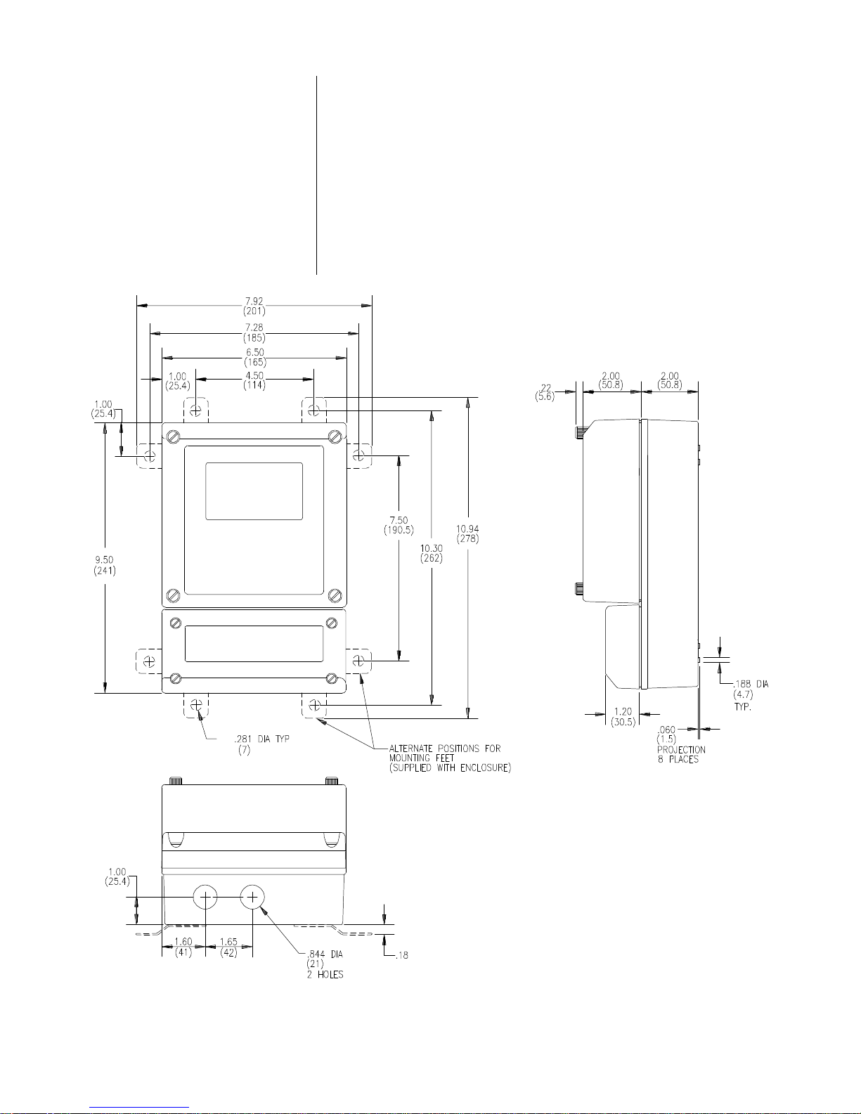
Refer to Figure 2-1 for enclosure and mounting dimension
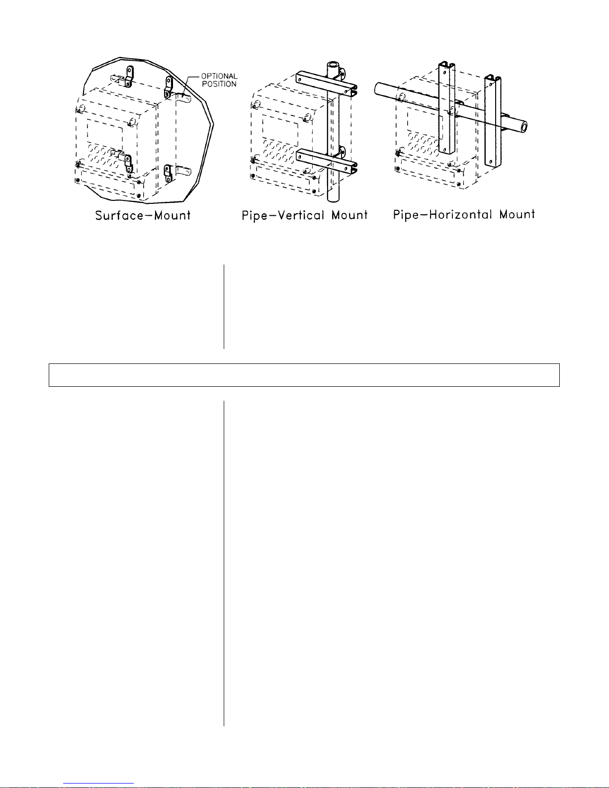
details. Figure 2-2 illustrates various mounting configurations. Use the four stainless steel tabs to surface-mount the
instrument. An optional hardware kit is required for pipe-
-10-
PART TWO - INSTALLATION SECTION 2- MECHANICAL REQUIREMENTS
mounting. The bracket attachment method determines vertical or horizontal pipe mounting configuration.
To surface mount the Model 692:
1. Place tabs in appropriate locations on back of enclosure
and fasten with screws provided.
2. Position instrument on flat surface and use appropriate
fasteners to secure it in place.
Rev. 9-898 Model 692P
FIGURE 2-1 Enclosure Outline
-11-
PART TWO - INSTALLATION SECTION 3 - ELECTRICAL CONNECTIONS
FIGURE 2-2 Mounting Configurations
2.3 Plugging Conduit
Holes
SECTION 3 - ELECTRICAL CONNECTIONS
3.1 GLI 5-Wire Differential
Technique Sensor
Use conduit hubs or cable feed-thru fittings where cables
enter the enclosure. Holes not used for cable entry should
be sealed with plugs.
NOTE: Use NEMA 4 rated fittings and plugs to maintain the
watertight integrity of the NEMA 4 enclosure.
To access terminal strips for electrical connections, loosen
bottom four captive fasteners and remove terminal compartment cover. Figure 3-2 shows terminal designations for
instrument hookup. If the transmitter is located in a hazardous area, refer to Section 3.5 for wiring details.
NOTE: For a CE-approved Model 692, the system must be
wired in accordance with GLI hookup drawing
1001X4N1306.
It is recommended that sensor signal wires be run in 1/2"
metal conduit for protection against moisture and mechanical damage. Do not run signal wires in same conduit with
power or control wiring (“electrical noise” may interfere with
sensor signal).
Model 692P Rev. 9-898
1. Place SWITCH 3 on back of display module assembly
(Figure 3-2) in DIFF. (off/right) position and TEMP.
COMP. switch to THERM.
2. Connect sensor (or interconnect cable) wires to
DIFFERENTIAL SENSOR terminals on TB2 (Figure 3-
2), matching colors as indicated.
-12-
PART TWO - INSTALLATION SECTION 3 - ELECTRICAL CONNECTIONS
3.2 Conventional
Combination Electrode
Direct Hookup
(distances less
1. Place SWITCH 3 on back of display module assembly
(Figure 3-2) in COMB. (on/left) position.
than 10 feet)
2. Active Electrode
Connect active electrode (center wire in coaxial or triax-
ial cable) to TB5 (ACTIVE) terminal post.
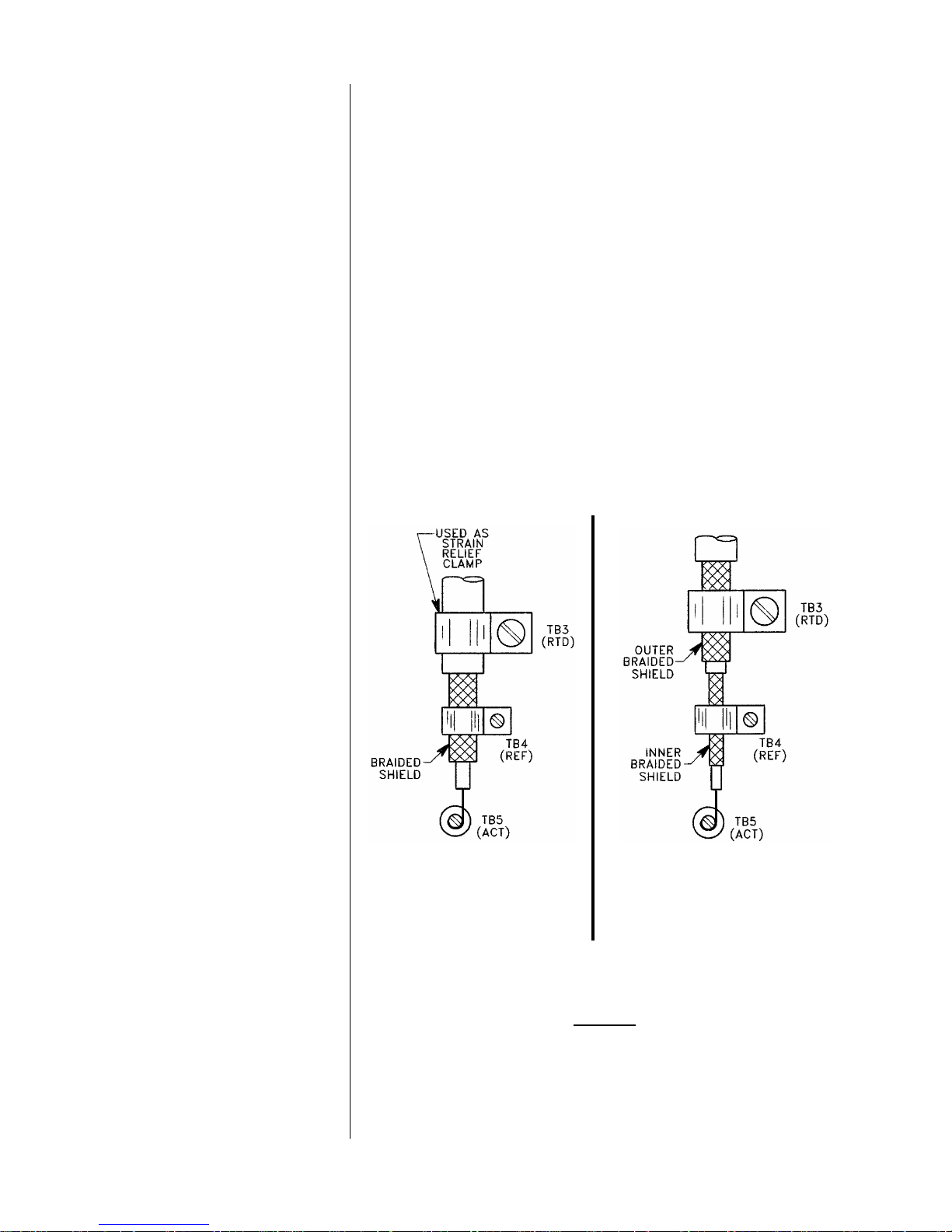
3. Reference Electrode
For a combination electrode that has a coaxial cable,
clamp the braided shield (reference electrode wire) under TB4 (REF.) terminal as shown in Figure 2-3.
If the electrode has a triaxial cable, clamp the inner
braided shield (reference electrode wire) under TB4
(REF.) terminal as shown in Figure 2-4.
Rev. 9-898 Model 692P
FIGURE 2-3 FIGURE 2-4
Connection Details for Connection Details for
Combination Electrode Combination Electrode
with Coaxial Cable with Triaxial Cable
4. Temperature Compensation Wiring
A. Automatic with Integral Temperature Sensor
1. The integral temperature sensor must be a 300
ohm thermistor or 1000 ohm RTD. Depending
which type of sensor it is, set TEMP.COMP.
switch to THERM. or RTD. position respectively.
-13-
PART TWO - INSTALLATION SECTION 3 - ELECTRICAL CONNECTIONS
2. For a combination electrode that has a coaxial
cable, connect separate temperature sensor wires
to TEMP COMP terminals on TB6 (Fig. 3-2).
If the electrode has a triaxial cable, clamp the
outer braided shield (temperature sensor wire)
under TB3 (RTD) terminal as shown in Figure 2-
4. In this case, set TEMP.COMP. switch to RTD.
position.
B. Automatic with Separate Temperature Sensor
1. The separate temperature sensor must be a 300
ohm thermistor or 1000 ohm RTD. Depending on
which type of sensor it is, set TEMP.COMP.
switch to THERM. or RTD. position respectively.
2. Connect separate temperature sensor (GLI p/n
60A2A9860-series) wires to TEMP COMP terminals on TB6 (Figure 3-2).
C. Fixed with External Resistor
1. Set TEMP.COMP. switch to THERM. position.
2. Connect the specific value resistor which corresponds with the desired temperature compensation across TEMP COMP terminals on TB6 (Fig.
3-2). The following table provides specific resistor
values required for the listed fixed temperature
compensation.
Table A RESISTOR VALUES FOR FIXED
TEMPERATURE COMPENSATION
°C
Resistor Value
(in ohms)
°C
Resistor Value
(in ohms)
0 771 55 114
5 631 60 99
10 519 65 85
15 430 70 74
20 358 75 65
25 300 80 57
30 252 85 50
35 213 90 44
40 181 95 39
45 155 100 35
50 133
Model 692P Rev. 9-898
-14-

PART TWO - INSTALLATION SECTION 3 - ELECTRICAL CONNECTIONS
Indirect Hookup
with Model 714 Preamp
(distances more
than 10 feet)
3.3 Power Supply
1. Place SWITCH 3 on back of display module assembly
(Figure 3-2) in DIFF. (off/right) position and TEMP.
COMP. switch to THERM.
2. Locate the GLI Model 714 preamp within 10 feet of the
combination electrode. Refer to the Model 714 preamp
instruction manual for electrical connection details between the combination electrode and the preamp.
3. The Model 692 can be located up to 3000 feet from the
Model 714 preamp. Connect interconnect cable from the
preamp to the Model 692 DIFFERENTIAL SENSOR terminals on TB2 (Figure 3-2), matching colors as
indicated.
Connect the DC voltage power supply to “4-20 mA” terminals on TB1, matching polarity as indicated.
NOTE: If the 692 is used in an intrinsically safe application,
it may be located in a Class I or II, Division 1 hazardous area without an explosionproof enclosure
when powered through an approved barrier. Refer
to Section 3.5 for details on hazardous area wiring
requirements.
3.4 Analog Output
The isolated 4-20 mA output can represent either the
measuring scale or a selected segment of it. To use the
range expand feature, refer to Part Three, Section 7.1 for
details.
The isolated 4-20 mA output can drive auxiliary devices (resistive loads) such as displays, recorders and computers,
provided that the voltage supplied by the power supply is
adequate. Devices must be wired in series with the transmitter and power supply. The voltage drop across the
load(s) and the 16 volts DC minimum needed to drive the
transmitter determines the minimum voltage required from
the power supply.
1. Determine the necessary voltage required to adequately
drive the Model 692 and auxiliary device(s).
A. The Model 692 acts as a current controlling device.
Thus, the current output remains the same even if
the power supply voltage fluctuates or the load resistance changes. The current varies only with
respect to the sensor signal, as long as the voltage
Rev. 9-898 Model 692P
-15-
PART TWO - INSTALLATION SECTION 3 - ELECTRICAL CONNECTIONS
drop across the transmitter is at least 16 VDC, but
not more than 40 VDC.
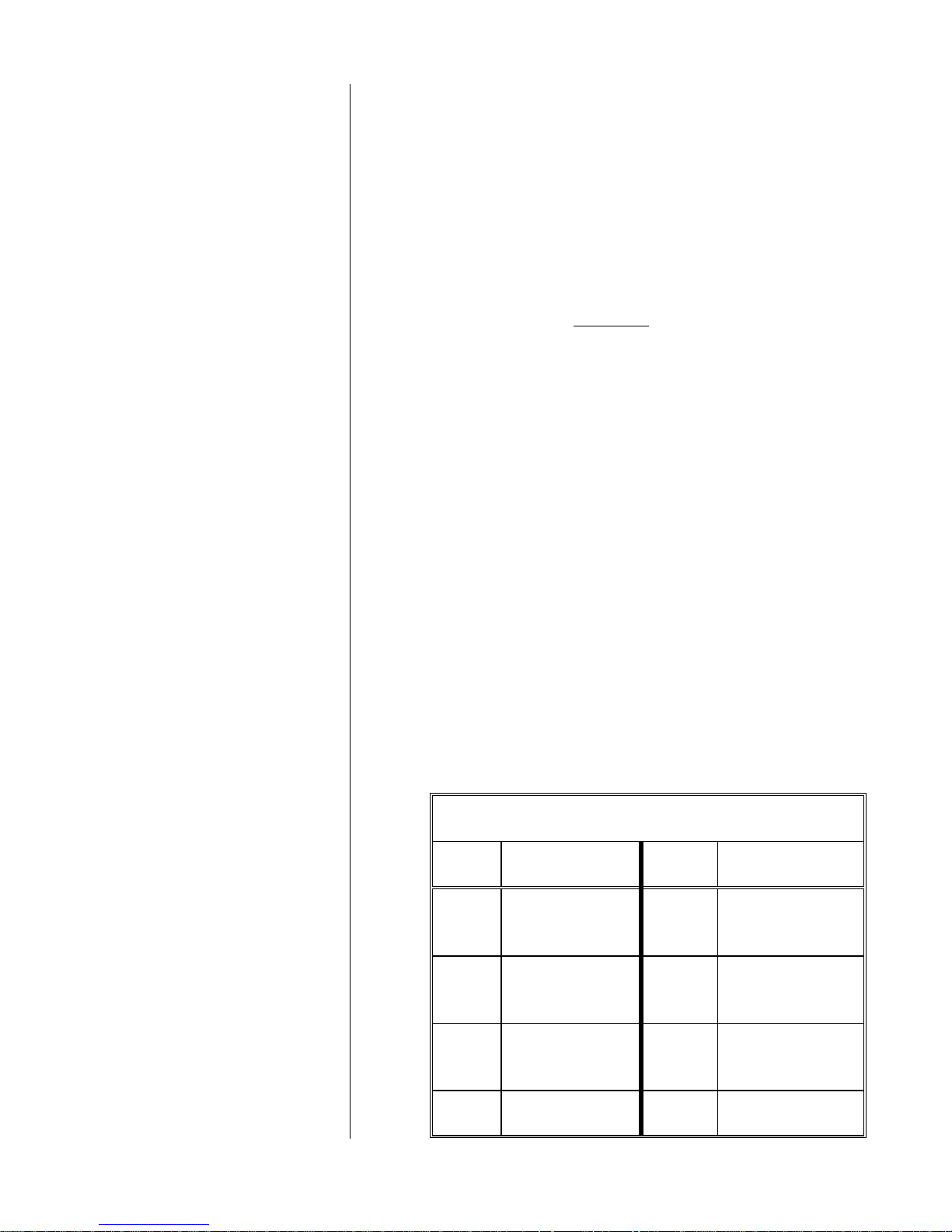
B. The load(s) in the circuit will generally have some
electrical resistance, 100 ohms for example. The 420 mA loop current will produce a voltage drop
across each load. The maximum voltage drop will
exist when the loop current is 20 mA. The power
supply must provide enough voltage for this drop
plus the 16 VDC minimum required for the Model
692. Two examples illustrate this point:
EXAMPLE 1
Sufficient Power Supply Voltage
Total Load Resistance = 300 ohms
At 20 mA loop current, the voltage drop across the load(s) is 6 volts:
300 ohms x 20 mA = 6,000 mV or 6 volts
Subtract 6 volts from the 24 volt source to determine that 18 volts is
available to power the Model 692. The 18 volts is within the specified 16 to 40 volt range and is sufficient to power the transmitter.
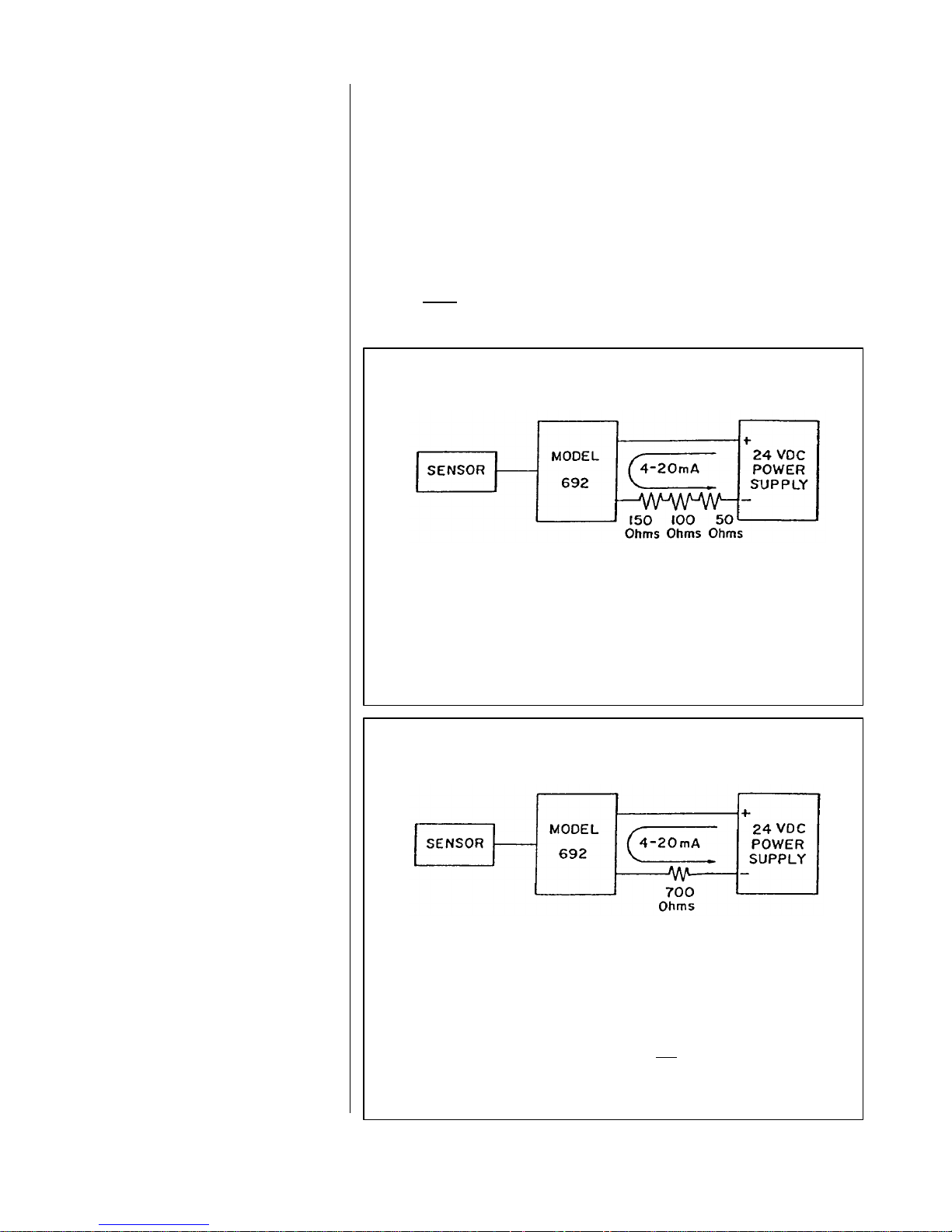
EXAMPLE 2
Insufficient Power Supply Voltage
Total Load Resistance = 700 ohms
At 20 mA loop current, the voltage drop across the load is 14 volts:
700 ohms x 20 mA = 14,000 mV or 14 volts
Subtract 14 volts from the 24 volt source to determine that 10 volts
is available to power the Model 692. The 10 volts is below the
specified 16 to 40 volt range and is not adequate to power the
transmitter. If, for example, the power supply voltage was 40 volts
instead of 24 volts, the voltage available to power the Model 692
would be 26 volts, well within the specified range.
Model 692P Rev. 9-898
-16-

PART TWO - INSTALLATION SECTION 3 - ELECTRICAL CONNECTIONS
2. Connect load(s) in series with transmitter and power
supply.
NOTE: Connecting the transmitter output to some types
of computers may cause the computer display
reading to fluctuate. This is caused by “electrical
noise” in the signal line. To correct this condition,
connect a 4.7 microfarad/80 volt, metal foil capacitor across the computer input.
3.5 Hazardous Area
Wiring (Intrinsically
Safe - Div. 1)
UL Classified
System
All Model 692P regulatory agency certifications for installation in a hazardous area require that the transmitter must
be:
n Powered by a power supply that provides no more than
28 volts DC.
n Powered through a Pepperl & Fuchs KHD3-ICR/Ex130
200 transformer isolated barrier (GLI p/n 1F1054).
Furthermore, each respective regulatory agency requires
that you meet additional specific conditions. Refer to the
appropriate agency subheading for details.
The 692P is UL Classified as intrinsically safe in a Class I
or II, Div. 1 hazardous area (Groups A through G) only
when:
1. Using a GLI pH sensor with a model number listed on
GLI control drawing 1001X4N1138.
CSA Certified
System
Rev. 9-898 Model 692P
2. Wiring the system in accordance with GLI control drawing 1001X4N1138.
The 692P is CSA Certified as intrinsically safe in a Class I
or II, Div. 1 hazardous area (Groups A through G) only
when:
1. Using a GLI pH sensor with a model number listed on
GLI control drawing 1001X4N1179.
2. Wiring the system in accordance with GLI control drawing 1001X4N1179.
-17-

PART TWO - INSTALLATION SECTION 3 - ELECTRICAL CONNECTIONS
Baseefa Approved
System
The 692P is Baseefa Approved as intrinsically safe in a
Zone 0 or 1 hazardous area (Groups IIC through IIA) only
when:
1. Using a GLI pH sensor with a model number listed on
GLI control drawing number 1001X4N1266.
2. Wiring the system in accordance with GLI control drawing 1001X4N1266.
Model 692P Rev. 9-898
-18-

PART THREE - OPERATION SECTION 1 - OPERATING CONTROLS
PART THREE - OPERATION
SECTION 1 - OPERATING CONTROLS
The frequently used keypad switches (Figure 3-1) can be
used without opening the instrument enclosure. Seldom
used setup controls are located on the backside of the display module assembly (Figure 3-2). To access them, loosen
the upper four screw-type fasteners and open the enclosure
door. You can easily remove the complete door/display
module assembly from the enclosure by unsnapping it from
its hinge and disconnecting the ribbon-cable connector.
WARNING: DO NOT ADJUST THE FACTORY-SEALED
(RED SEALANT) POTENTIOMETERS. IF SEALS ARE
BROKEN, THE INSTRUMENT WARRANTY IS VOIDED. IF
THE INSTRUMENT IS RETURNED TO GLI AND ANY OF
THE FACTORY-SEALED POTENTIOMETERS REQUIRES
RE-ADJUSTMENT, A FACTORY SETUP CHARGE WILL
BE INCURRED.
1.1 Keypad Switches
All switches, status indicators and program jumpers used for
instrument operation are described in this section. Familiarize yourself with each item before operating the
instrument.
1. EXAM/CANCEL key (Figure 3-1)
Selects the normal “measurement” display mode or an
“examination” display mode. Successive key presses
alternate the display between these two modes.
n In measurement mode:
Display shows measured variable selected with DISP
VAR key: pH, temperature, the sensor's mV signal, or
the 4-20 mA instrument output.
n In “examination” mode:
Display shows setup variables and their stored values. Setup data such as calibration values, low and
high endpoints for range expand, etc. are called up in
the sequence shown in Figure 3-3 by pressing the
NEXT key (item 2). Values can be changed by using
the ññ and ïï keys (items 3 and 4) and are entered
by pressing the ENTER/CANCEL HOLD key (item
5). Any entry routine may be cancelled by pressing
the EXAM/CANCEL key which also returns display to
normal measurement mode.
Rev. 9-898 Model 692P
-19-

PART THREE - OPERATION SECTION 1 - OPERATING CONTROLS
2. NEXT key (Figure 3-1)
n With display in measurement mode:
This key has no effect.
n With display in “examination” mode:
Scrolls display to show next setup variable with each
press. Refer to Tables B, C, and D in Section 3 for a
complete listing of all setup variables.
3. ññ key (Figure 3-1)
n With display in measurement mode:
This key has no effect.
n With display in “examination” mode:
Increases flashing digit value by one with each key
press or continually advances digit value from 0 thru
9 by holding key down. This key is used with ïï key
(item 4) to change displayed value to a new value.
Model 692P Rev. 9-898
FIGURE 3-1 Keypad Switches
-20-

PART THREE - OPERATION SECTION 1 - OPERATING CONTROLS
4. ïï key (Figure 3-1)
n With display in measurement mode:
This key has no effect.
n With display in “examination” mode:
Progressively selects the next digit to the left to flash
with each press-and-release so that its value can be
changed with the ññ key (item 3). The flashing digit
“wraps around” from far left to far right.
5. ENTER/CANCEL HOLD key (Figure 3-1)
n With display in measurement mode:
Cancels output hold feature when pressed together
with OUTPUT key (item 9).
n With display in “examination” mode:
A. Enters displayed value into memory (if within ac-
ceptable range) for the indicated setup variable.
Display flashes “OK” for approximately 5 seconds
to confirm entry.
B. Cancels output hold feature when pressed to-
gether with OUTPUT key (item 9).
6. DISP VAR key (Figure 3-1)
n With display in measurement mode:
Scrolls display with each key press to show the following measured variables: pH, temperature (°C or
°F), the sensor's mV signal, and the 4-20 mA instrument output.
NOTE: To check the display to make sure all indi-
cators light up (as shown in Figure 3-1),
display the 4-20 mA output variable and
press the EXAM/CANCEL key.
Rev. 9-898 Model 692P
n With display in “examination” mode:
This key has no effect.
-21-

PART THREE - OPERATION SECTION 1 - OPERATING CONTROLS
7. BEGIN CAL key (Figure 3-1)
n With display in measurement mode:
A. Displays stored value for LO or HI CAL VALUE
setup variable used in “two-key” calibration (twopoint or table method). Each key press alternately
displays both stored values. To return display to
normal indication, pressed EXAM/CANCEL key.
B. Initiates calibration of a point used in “two-key”
calibration (two-point or table method). Specific
buffer values should be stored in memory before
using this key to initiate calibration (see Part
Three, Section 6.4 or 6.5 for details).
n With display in “examination” mode:
This key has no effect.
8. END CAL/HOLD recessed button (Figure 3-1)
n With display in measurement mode:
Activates output hold feature when pressed together
with OUTPUT key (item 9).
n With display in “examination” mode:
A. Completes calibration of a point used in “two-key”
two-point or “two-key” table method.
B. Activates output hold feature when pressed to-
gether with OUTPUT key (item 9).
9. OUTPUT key (Figure 3-1)
With display in measurement or “examination” mode:
A. Activates output hold feature when pressed together
with recessed END CAL/HOLD button.
B. Cancels output hold feature when pressed together
with ENTER/CANCEL HOLD key.
1.2 Slide Switches
Model 692P Rev. 9-898
10. SWITCH 2 (Figure 3-2)
Selects the state that the instrument will default to during
an out-of-range condition due to a defective pH sensor
or shorted sensor cable. The operator presets a low or
high out-of-range default state. In case of failure,
-22-

PART THREE - OPERATION SECTION 1 - OPERATING CONTROLS
this prevents a pump or valve from operating, therefore
conserving use of costly chemicals. For example, the
process may typically be controlled between 7 and 8 pH
with a tendency to increase without chemical addition. If
an out-of-range condition occurs in this example, you
can be prevent unwanted chemical addition by presetting the Model 692 for a low out-of-range default state.
This causes the display to indicate 0 pH and provides
the corresponding loop current (4 or 20 mA).
0 pH POSITION (on/left) - Selects the low out-of-range
state default. When the 692 detects a defective pH sensor or shorted sensor cable, the display indicates 0 pH
with an “ERR 1” or “ERR 3” diagnostic message, and the
692 provides a corresponding loop current (4 or 20 mA).
14 pH POSITION (off/right) - Selects the high out-of-range
state default. When the 692 detects a defective pH sensor
or shorted sensor cable, the display indicates 14 pH with
an “ERR 1” or “ERR 3” diagnostic message, and the unit
provides a corresponding loop current (4 or 20 mA).
11. SWITCH 3 (Figure 3-2)
COMB. POSITION (on/left) - Sets the 692 for use with a
combination electrode.
DIFF. POSITION (off/right) - Sets the 692 for use with a
GLI 5-wire Differential Technique sensor.
12. SWITCH 4 (Figure 3-2)
°F POSITION (on/left) - Selects measured temperature
to be displayed in °F.
°C POSITION (off/right) - Selects measured tempera-
ture to be displayed in °C.
13. TEMP. COMP. switch (Figure 3-2)
RTD - Sets the 692 for use with a 1000 ohm RTD
temperature sensor for automatic temperature compensation.
Rev. 9-898 Model 692P
THERM. - Sets the 692 for use with a 300 ohm thermistor temperature sensor for automatic temperature
compensation (or a specific-valued resistor for fixed
temperature compensation).
-23-

PART THREE - OPERATION SECTION 1 - OPERATING CONTROLS
1.3 Program Jumper 14. BATTERY jumper (Figure 3-2)
ON - Connects battery to store user-entered setup vari-
able values even when power is lost or turned off.
OFF - Disconnects battery when the 692 is not to be
used for an extended time.
CAUTION: If loop power is removed from the 692
and you disconnect the backup battery, all stored
setup values will revert back to factory defaults.
FIGURE 3-2 Controls on Backside of Display Module Assembly and Electrical Hookup Details
Model 692P Rev. 9-898
-24-

PART THREE - OPERATION SECTION 2 - MEASURED VARIABLES
1.4 Status Indicators 15. HOLD indicator (LCD display)
Indicates that the output hold feature is in use (Model
692 output value is maintained).
NOTE: After 30 minutes, HOLD indicator flashes to in-
dicate that output hold feature will be
automatically cancelled in 30 seconds. Pressing
OUTPUT key extends hold feature for another
30 minutes.
16. OK indicator (LCD display)
Flashes for approximately 5 seconds to confirm suc-
cessful entry of a setup variable value.
17. LOCK indicator (LCD display)
Indicates that Model 692 keypad entry is “locked” to
prevent unauthorized alteration of stored setup variable
values. Refer to Section 8 for security lock feature instructions.
NOTE: When the 692 is locked, you can still enter cali-
bration values and display stored entry values.
18. ERROR indicator (LCD display)
Flashes to indicate an incorrect entry or alternately
flashes with “Err 1”, “Err 2”, “Err 3” or “Err 4” to indicate
a system diagnostic error causing improper system operation.
SECTION 2 - MEASURED VARIABLES
The Model 692 can display four measured variables. With
the display in the measurement mode, each press of the
DISP VAR key sequentially displays:
Rev. 9-898 Model 692P
n pH.
n Temperature in °C or °F.
n The sensor's mV signal.
n The 4-20 mA instrument analog output.
-25-

PART THREE - OPERATION SECTION 3 - SETUP VARIABLES
SECTION 3 - SETUP VARIABLES
3.1 Calling Up
Setup Variables
3.2 Entering Values
1. Pressing the EXAM/CANCEL key while the display is in
the measurement mode changes the readout to an “examination” mode to show setup variables. The pH,
temperature, and mV displays each have a corresponding menu showing related setup variables to configure
the instrument.
2. Each press of the NEXT key displays the next setup
variable, in sequence, for its respective menu. Within
each menu, setup variables “wrap around” from last to
first.
Pressing the EXAM/CANCEL key at any time returns the
display to the measuring mode.
Use the ññ and ïï keys to change displayed setup values.
Each press of the ññ key increases the flashing digit value
by one. Holding down this key continually advances the
value. Pressing and releasing the ïï key selects the next
digit to the left (digit flashes) so it can be changed using the
ññ key. After establishing the desired value, press the
ENTER key to store it in memory. Thereafter, “OK” flashes
for approximately 5 seconds to confirm that the entry was
accepted, or “ERROR” flashes if the entry was invalid.
3.3 Setup Variables
Call-Up Chart and
Table of Descriptions
Figure 3-3 on the following page shows the four measured
variable display modes (shaded boxes at top of chart), and
their respective setup variable menus in the call-up order.
When using the output hold feature, the “SIM VALUE” setup
variable cannot be used or displayed (see footnote at bottom of chart).
Model 692P Rev. 9-898
-26-

PART THREE - OPERATION SECTION 3 - SETUP VARIABLES
All display
segments light
E
X
A
M
/
C
A
N
C
E
L
NEXT
NEXT
NEXT
NEXT
NEXT
"HI BUFFER
OUT VALUE"
OUT VALUE"
"LO BUFFER
E
X
A
M
/
C
A
N
C
E
L
E
X
A
M
/
C
A
N
C
E
L
E
X
A
M
/
C
A
N
C
E
L
E
X
A
M
/
A
N
C
E
L
R
e
l
e
a
s
e
E
X
A
M
/
C
A
N
C
E
L
DISP. VAR
DISP. VAR
X
A
M
/
A
N
C
E
L
"BUFFER CAL"
pH Display
C
EXAM /
CANCEL
EXAM /
CANCEL
EXAM/
CANCEL
EXAM/
CANCEL
"CAL
VALUE"
NEXT
"LO CAL
VALUE"
NEXT
"HI CAL
VALUE"
NEXT
"SLOPE"
DISP. VARDISP. VAR
EXAM /
CANCEL
EXAM /
CANCEL
EXAM/
CANCEL
NEXT
Temperature
Display
"CAL
VALUE"
NEXT
"LO CAL
VALUE"
NEXT
"HI CAL
VALUE"
NEXT
EXAM /
CANCEL
EXAM /
CANCEL
mV Display
"CAL
VALUE"
"LO CAL
VALUE"
"HI CAL
VALUE"
mA Display
NEXT
NEXT
EXAM/
CANCEL
EXAM/
CANCEL
"0000"
(Lock)
"SIM VALUE"
1
Displayed only when the output hold feature is not in use.
NEXT
1
NEXT
VALUE"
EXAM/
CANCEL
VALUE"
EXAM/
CANCEL
"LO
EXAM/
CANCEL
"HI
E
C
E X A M /
C A N C E L
FIGURE 3-3 Display Modes and Call-up Chart of Setup Variables
NEXT
Rev. 9-898 Model 692P
-27-

PART THREE - OPERATION SECTION 3 - SETUP VARIABLES
The following tables for each of the three setup variable
menus list the setup variables in exact order of call-up, their
use, entry value range, and factory default value. Use the
far right column to write in your entered setup values for
convenient referral.
Table B - DESCRIPTION OF pH SETUP VARIABLES
Entry Value
Displayed Use
Identifier
“CAL
VALUE”
“LO CAL
VALUE”
“HI CAL
VALUE”
“SLOPE” Display only of 0-100% slope (0-59mV/pH).
“0000” Activates the security lock feature. 0000 9999 0000
“SIM VALUE”
“LO BUFFER
VALUE”
“HI BUFFER
VALUE”
“LO
OUT VALUE”
“HI
OUT VALUE”
“BUFFER CAL”
Sets calibration point for conventional single-point
pH calibration.
Sets low calibration point for conventional two-point
pH calibration.
Sets high calibration point for conventional two-point
pH calibration.
Sets simulated pH value for diagnostic purposes. The
∆
analog output responds to the displayed value.
Sets the value of lower buffer used for
“two-key” pH calibration: Two point method
Table method
Sets the value of higher buffer used for
“two-key” pH calibration: Two-point method
Table method
Sets low endpoint of pH measuring range at which the
minimum output (4 mA) is provided.
Sets high endpoint of pH measuring range at which the
maximum output (20 mA) is provided.
Selects two-point or table method for “two-key” pH
calibration.
Range Default
Min. Max.
0.00 14.00 7.00
0.00 10.00 4.00
2.00 12.00 10.00
0.00 14.00 7.00
0.00
1.09
2.00
3.56
0.00 14.00 0.00
0.00 14.00 14.00
tABL 2 Pt 2 Pt
10.00
10 A
12.00
12.45
Record
Your
Value Entry
ê
4.00
4.00
10.00
10 A
∆
Only provided and displayed when the output hold feature is not in use.
Table C - DESCRIPTION OF TEMPERATURE SETUP VARIABLES
Displayed Use
Identifier
“CAL
VALUE”
“LO CAL
VALUE”
“HI CAL
VALUE”
Model 692P Rev. 9-898
Sets calibration point for single-point
temperature calibration: °C
Sets low calibration point for two-point
temperature calibration: °C
Sets high calibration point for two-point
temperature calibration: °C
-28-
°F
°F
°F
Entry Value
Range Default
Min. Max.
0.0
100.0
32.0
32.0
25.0
77.0
0.0
212.0
30.0
86.0
100.0
212.0
Record
Your
Value Entry
ê
25.0
77.0
0.0
32.0
100.0
212.0

PART THREE - OPERATION SECTION 4 - INSTRUMENT STARTUP
Table D - DESCRIPTION OF mV SETUP VARIABLES
Displayed Use
Identifier
“CAL
VALUE”
“LO CAL
VALUE”
“HI CAL
VALUE”
Sets calibration point for single-point millivolt
calibration.
Sets low calibration point for two-point millivolt
calibration.
Sets high calibration point for two-point millivolt
calibration.
SECTION 4 - INSTRUMENT STARTUP
4.1 Checking Battery
Backup Jumper
4.2 Setting Sensor
Input Type
Entry Value
Range Default
Min. Max.
(-)500 (+)500 (+)200
(-)500 (+)50 (-)180
(+)100 (+)500 (+)180
Value Entry
Record
Your
ê
In case loop power is lost, an internal battery powers the
Model 692 memory to retain all user-entered setup variable
values. The 692 is supplied with its BATTERY jumper (Figure 3-2) in the OFF position. Make sure to place this jumper
in the ON position before proceeding.
You must set the 692 sensor input to accept the type of
sensor that will be used.
GLI 5-Wire
Differential Technique
Sensor
Conventional
Combination Electrode
1. Locate the group of four switches on back of display
module assembly (Figure 3-2) and place SWITCH 3 in
DIFF. (off/right) position.
2. Set TEMP. COMP. switch to THERM position.
# # #
1. Direct Hookup (distances less than 10 feet)
A. Locate the group of four switches on back of display
module assembly (Figure 3-2) and place SWITCH 3
in COMB. (on/left) position.
B. Depending on the type of temperature sensor used
for temperature compensation, set TEMP. COMP.
switch as follows:
a. When using a 1000 ohm RTD, place in RTD po-
sition.
Rev. 9-898 Model 692P
b. When using a 300 ohm thermistor or a fixed re-
sistor, place in THERM position.
-29-

PART THREE - OPERATION SECTION 5 - TEMPERATURE CALIBRATION
2. Indirect Hookup with Model 714 Preamp (distances more
than 10 feet)
A. Locate the group of four switches on back of display
module assembly (Figure 3-2) and place SWITCH 3
in COMB. (on/left) position.
B. Set TEMP. COMP. switch to THERM position.
4.3 Selecting Temperature
Display Units (°°C or °°F)
4.4 Understanding
Calibration
4.5 Selecting Default State
for Out-of-Range
Condition
SECTION 5 - TEMPERATURE CALIBRATION
5.1 Temperature Effects
on pH Reading
Locate the group of four switches on back of display module
assembly (Figure 3-2) and place SWITCH 4 in °°F (on/left)
position for temperature values to be displayed in °F. Place
in opposite °°C (off/right) position for °C readout.
Before initially calibrating the instrument, read Section 5.1
“Temperature Effects on pH Reading” and Section 6.1
“Summary of Methods”. Then calibrate the instrument using
the desired method.
When an out-of-range condition occurs due to a defective
pH sensor or shorted sensor cable, the instrument will respond according to the default state selected with SWITCH
2 (Figure 3-2). Refer to Section 1.2 - item 10 for details
about this switch and its settings.
The instrument automatically compensates the pH reading
for changes in temperature and has temperature calibration
capabilities. For best accuracy, it is recommended to initially calibrate the instrument for temperature before
calibrating for pH measurement.
300 Ohm
Thermistor
Compensation
1000 Ohm RTD
Compensation
Model 692P Rev. 9-898
When using a GLI Differential Technique pH sensor or a pH
combination electrode with a 300 ohm thermistor, you can
disregard temperature calibration. (The 692 is factorycalibrated for this temperature sensor.) If, however, you
require extremely accurate temperature measurement, perform a single or two-point temperature calibration (Section
5.2 or 5.3) before calibrating the 692 for pH measurement.
When using a pH combination electrode with a 1000 ohm
RTD, always perform a two-point temperature calibration
before calibrating for pH to obtain the most accurate pH
readings.
-30-

PART THREE - OPERATION SECTION 5 - TEMPERATURE CALIBRATION
Fixed Resistor
Compensation
5.2 Single-Point Method
When using a pH combination electrode with an external
resistor for fixed temperature compensation, always perform
a single-point temperature calibration to provide the best pH
measurement accuracy. Instead of normally entering the
known temperature value of the process, enter the temperature compensation value (in °C) corresponding to the
value of the external resistor being used (see Table A on
page 14).
This method requires a container of water (or process solution) that has a known temperature value approximately
equal to the normal operating temperature of the process.
1. Place temperature sensor in water (or process solution)
of known temperature value.
2. Press DISP VAR key as needed to display temperature
and allow the reading to stabilize. The sensor may take
several minutes to attain temperature equilibrium with
the solution.
3. Press EXAM/CANCEL key to place display in “examination” mode and to indicate temperature “CAL VALUE.”
4. Use ïï and ññ keys to make display indicate the
known temperature value of the solution.
5. Press ENTER key to enter value (display flashes “OK” to
confirm entry and returns to temperature measuring
mode). “HI/LO ERROR” flashes if the difference between
the entry value and actual solution temperature is
greater than 5.0°C.
5.3 Two-Point Method
Rev. 9-898 Model 692P
This completes the single-point temperature calibration.
This method requires a container of ice water and a con-
tainer of water (or process solution) that has a known
temperature value of 90-100°C (194-212°F) or is approximately equal to the normal operating temperature of the
process.
1. Place temperature sensor in ice water.
2. Press DISP VAR key as needed to display temperature
and allow display reading to stabilize. The sensor may
take several minutes to attain temperature equilibrium
with the solution.
-31-

PART THREE - OPERATION SECTION 6 - pH CALIBRATION
3. Press EXAM/CANCEL key to place display in “exami-
nation” mode.
4. Press NEXT key once to make display indicate tem-
perature “LO CAL VALUE”.
5. Use ïï and ññ keys to make display indicate “0.0°C”
(or “32.0°F”).
6. Press ENTER key to enter value (display flashes “OK”
to confirm entry and returns to temperature measuring
mode). If “HI/LO ERROR” flashes, the difference between the entry value and actual solution temperature
is greater than 10.0°C.
7. Place temperature sensor in the known higher tem-
perature water (or process solution). Allow sensor to
attain temperature equilibrium with the solution.
8. Press EXAM/CANCEL key to place display in “exami-
nation” mode.
9. Press NEXT key twice to make display indicate tem-
perature “HI CAL VALUE.”
10. Use ïï and ññ keys to make display indicate the
known temperature value.
NOTE: Entry value must be between 25.0 and 100.0°C
and at least 10.0°C higher than the lower calibration point (0.0°C from step 5).
11. Press ENTER key to enter value (display flashes “OK”
to confirm entry and returns to temperature measuring
mode). “VALUE ERROR” flashes if the difference between entry values is less than 10.0°C. If “HI/LO
ERROR” flashes, entry value is out of range (less than
25.0°C or greater than 100.0°C) or the difference between the entry value and actual solution temperature
is greater than 10.0°C.
This completes the two-point temperature calibration.
SECTION 6 - pH CALIBRATION
Model 692P Rev. 9-898
The instrument must be calibrated periodically with pH
buffer solution(s) to maintain measurement accuracy. It is
highly recommended to establish a maintenance program to
-32-

PART THREE - OPERATION SECTION 6 - pH CALIBRATION
keep the sensor clean and the instrument calibrated. The
time period between performing maintenance (days, weeks,
etc.) is affected by the characteristics of the process solution and can only be determined by operating experience.
For example, a sensor operating in wastewater that contains oil and/or grease may require more frequent cleaning.
6.1 Summary of Methods
The instrument can be calibrated for pH in a number of different ways. Use the conventional single or two-point
method (Section 6.2 or 6.3 respectively) when you want to
actually enter the known buffer values into memory.
NOTE: The conventional two-point method is highly recom-
mended for initial calibration or when the pH sensor
has been replaced.
Two alternate “two-key” calibration methods are also available. These methods are highly recommended for the
novice operator since they eliminate the need for that person to enter buffer values, making them especially
convenient. When using the “two-key” two-point calibration
method (Section 6.4), a qualified person initially enters two
buffer values. Anytime thereafter, a novice operator can accurately calibrate the instrument for each point by simply
pressing two keys. The only requirement is placing the sensor in the appropriate buffer for each calibration point.
The other “two-key” calibration method is the table method
(Section 6.5). It is similar to the “two-key” two-point method
except that a qualified person initially selects the buffer values from a table of 14 specific buffer formulations. This
method provides the most accurate calibration because errors caused by small changes in buffer value due to
temperature variations are eliminated by the built-in pHversus-temperature curve related to that buffer. Also, the
instrument automatically recognizes and differentiates between the two pre-selected buffers during calibration. The
operator need not know the buffer values.
6.2 Conventional
Single-Point
Method
Rev. 9-898 Model 692P
This procedure requires a clean sensor and one fresh, accurate pH buffer with a value reasonably close to the normal
pH of the process (pH 7, 4, or 10 buffer is recommended
and readily available).
1. With display in pH measuring mode, place clean sensor,
with protective caps removed, in the known buffer. Allow
display reading to stabilize. The sensor may take several minutes attaining temperature equilibrium with the
buffer.
-33-

PART THREE - OPERATION SECTION 6 - pH CALIBRATION
NOTE: If a pH combination electrode is used with an
external temperature sensor, place the temperature sensor in the buffer along with the
electrode. If an external resistor is used for fixed
temperature compensation (Table A on page
14), it is recommended to bring the temperature
of the buffer to that specific temperature for best
accuracy.
2. Press EXAM/CANCEL key to place display in “examination” mode and to indicate pH “CAL VALUE.”
3. Use ïï and ññ keys to make display indicate the
known pH value of the buffer (from table on buffer bottle).
4. Press ENTER key to enter value (display flashes “OK” to
confirm entry and returns to pH measuring mode).
This completes the conventional single-point pH calibration.
6.3 Conventional
Two-Point
Method
This procedure requires a clean sensor and two fresh, accurate pH buffers. pH 7 and pH 4 buffers are recommended
and are readily available. If pH 4 buffer is not available,
substitute pH 10 buffer.
1. With display in pH measuring mode, place clean sensor,
with protective caps removed, in the lower value buffer.
Allow display reading to stabilize. The sensor may take
several minutes to attain temperature equilibrium with
the buffer.
NOTE: If a pH combination electrode is used with an
external temperature sensor, place the temperature sensor in the buffer along with the
electrode during this step and step 6. If an external resistor is used for fixed temperature
compensation (Table A on page 14), it is recommended to bring the temperature of buffer
used in this step and step 6 to the fixed compensation temperature for best accuracy.
2. Press EXAM/CANCEL key to place display in “examination” mode.
Model 692P Rev. 9-898
3. Press NEXT key once to make display indicate pH “LO
CAL VALUE.”
4. Use ïï and ññ keys to make display indicate the value
of the lower pH buffer (from table on buffer bottle).
-34-

PART THREE - OPERATION SECTION 6 - pH CALIBRATION
NOTE: Entry value must be between 0.00 and 10.00 pH
and at least 1.00 pH lower than the value of the
higher calibration point.
5. Press ENTER key to enter value (display flashes “OK” to
confirm entry and returns to pH measuring mode).
NOTE: If display indicates “Err 1” diagnostic message,
ignore it and proceed with step 6. This message
indicates that the new LO CAL VALUE entry is
significantly different than the previously entered
calibration values. After the HI CAL VALUE is
entered (step 10), the “Err 1” message will cancel
and the display will return to normal indication.
6. Remove sensor from lower value buffer. Rinse sensor in
clean water and place in higher value buffer. Allow sensor to attain temperature equilibrium with the buffer.
7. Press EXAM/CANCEL key to place display in “examination” mode.
8. Press NEXT key twice to make display indicate pH “HI
CAL VALUE.”
9. Use ïï and ññ keys to make display indicate the value
of the higher pH buffer (from table on buffer bottle).
6.4 “Two-Key”
Two-Point Method
NOTE: Entry value must be between 2.00 and 12.00 pH
and at least 1.00 pH higher than the value of the
lower calibration point.
10. Press ENTER key to enter value (display flashes “OK” to
confirm entry and returns to pH measuring mode).
“VALUE ERROR” flashes if the difference between entry
values is less than 1.00 pH.
This completes the conventional two-point pH calibration.
Use the conventional two-point method (Section 6.3) to ini-
tially calibrate the instrument, including when the pH sensor
has been replaced. Thereafter, you can use the “two-key”
two-point method, but first a qualified person must:
n Set the instrument for this method.
Rev. 9-898 Model 692P
-35-

PART THREE - OPERATION SECTION 6 - pH CALIBRATION
n Enter pH buffer (or known process solution) values to
be used as the two calibration points.
Thereafter, the instrument can be periodically calibrated
using the procedure described under the “Performing Calibration” subheading.
Selecting
This Method
Entering Calibration Points
(by qualified person)
1. With display in pH measuring mode, press EXAM/
CANCEL key to place display in “examination” mode.
2. Press NEXT key until display indicates “BUFFER CAL.”
3. Press ïï key to make display indicate “2 Pt.”
4. Press ENTER key to select “two-key” two-point method
(“OK” flashes to confirm entry).
# # #
1. Press NEXT key until display indicates “LO BUFFER
VALUE.”
2. Use ïï and ññ keys to make display indicate the de-
sired value for the lower calibration point.
NOTE: Entry value must be 10.00 pH or lower.
3. Press ENTER key to enter value (“OK” flashes to confirm entry).
4. Press NEXT key once to make display indicate “HI
BUFFER VALUE.”
5. Use ïï and ññ keys to make display indicate the de-
sired value for the higher calibration point.
NOTE: Entry value must be at least 2.00 pH units higher
than the value of the lower calibration point.
6. Press ENTER key to enter value (display flashes “OK” to
confirm entry or “VALUE ERROR” if difference between
entry value and LO BUFFER VALUE is less than 2.00
pH units).
7. Press EXAM/CANCEL key to return display to pH
measuring mode.
Performing Calibration
Model 692P Rev. 9-898
Use this “two-key” two-point method to calibrate the instrument after both calibration points have been entered. This
-36-

PART THREE - OPERATION SECTION 6 - pH CALIBRATION
calibration procedure requires a clean sensor and two fresh,
accurate pH buffers (or known process solutions) that have
the same values as the two preset calibration points.
1. Place clean sensor, with protective caps removed, in the
lower value buffer.
NOTE: If a pH combination electrode is used with an
external temperature sensor, place the temperature sensor in the buffer along with the
electrode during this step and step 4. If an external resistor is used for fixed temperature
compensation (Table A on page 14), it is recommended to bring the temperature of buffer
used in this step and step 4 to the fixed compensation temperature for best accuracy.
2. With display in pH measuring mode, press BEGIN CAL
key (display indicates one of the preset values “LO
CAL VALUE” or “HI CAL VALUE”). If display indicates
the higher value, press BEGIN CAL key again to display
lower value.
After pressing BEGIN CAL, you have 30 minutes to com-
plete the calibration of this point. During the routine,
another 30 minutes can be added by pressing any key
except END CAL.
The instrument checks the stability of the pH and tempera-
ture inputs. As each input changes, the respective pH
and °C (or °F) indicator flashes. When each input is stable, the respective indicator stops flashing and remains
on.
When the pH and °C (or °F) indicators are both on (not
flashing), press recessed END CAL button using a slender tool. The instrument checks that:
Rev. 9-898 Model 692P
n The pH input has a slope between 51 and 62 mV/pH.
If not, the display flashes “HI/LO SLOPE ERROR.”
n The pH input offset is within ±1.50 pH of the entry
value. If not, the display flashes “HI/LO ERROR.”
n This calibration point is at least 2.00 pH away from
the other calibration point. If not, the display flashes
“BUFFER VALUE ERROR.”
When these conditions are met, the display flashes “OK”
-37-

PART THREE - OPERATION SECTION 6 - pH CALIBRATION
to confirm entry was made and returns to the pH measuring mode.
NOTE: If display flashes “HI/LO SLOPE ERROR” or
“HI/LO ERROR,” an incorrect buffer value may
have been used or the sensor may be dirty or
defective. If the correct buffer value was used,
calibrate the instrument using the conventional
two-point method (Section 6.3) to check the
sensor slope which is based on the last successful calibration. Refer to Part Four, Section
1.3 for details on checking sensor slope.
4. Remove sensor from lower value buffer. Rinse sensor in
clean water and place in the higher value buffer.
5. Press BEGIN CAL key to initiate calibration of the second calibration point.
6. When the pH and °C (or °F) indicators are both on (not
flashing), press recessed END CAL button using a slender tool. See step 3 for additional details.
6.5 “Two Key”
Table Method
This completes the “two-key” two-point pH calibration.
Any buffer has some variation of pH value with temperature,
but few operators take the time to measure the buffer temperature with the sensor at equilibrium, and then enter the
pH of the buffer at that temperature. The basis for this “twokey” table method is that the 692 has the built-in pH valueversus-temperature curve for a set of buffers and monitors
the temperature and time response when the sensor is put
into a buffer. Using this method provides the most accurate
calibration.
Use the conventional two-point method (Section 6.3) to initially calibrate the instrument, including when the pH sensor
has been replaced. Thereafter, you can use the “two-key”
table method, but first a qualified person must:
n Set the instrument for this method.
n Select and enter one or two pH buffer values from the
buffer table to be used as the calibration point(s).
Model 692P Rev. 9-898
Thereafter, the instrument can be periodically calibrated
using the procedure described under the “Performing Calibration” subheading beginning on page 40.
-38-

PART THREE - OPERATION SECTION 6 - pH CALIBRATION
Selecting
This Method
Entering Calibration Points
(by qualified person)
1. With display in pH measuring mode, press EXAM/
CANCEL key to place display in “examination” mode.
2. Press NEXT key until display indicates “BUFFER CAL.”
3. Press ïï key to make display indicate “tAbL.”
4. Press ENTER key to select “two-key” table method
(“OK” flashes to confirm entry).
# # #
1. The following table lists the selection of pH values and
their buffer formulations. Choose and note one or two
table pH values for use as the calibration point(s).
NOTE: When two calibration point values are selected,
they must be at least one table value apart from
each other (non-adjacent values).
Table E BUFFER VALUES FOR
“TWO-KEY” TABLE METHOD
pH Buffer Value Buffer Formulation
1.09 HCl (DIN 19267)
1.68 Tetraoxalate (NBS 260-53)
3.56 Tartrate (NBS 260-53)
3.78 Citric acid (DIN 19266)
4.00* Pthalate (DIN 19266)
4.01 Pthalate (NBS 260-53)
4.65 Acetate (DIN 19267)
6.87 Phosphate (DIN 19266)
7.00 Phosphate
7.41 Phosphate (DIN 19266)
9.18 Borax (NBS 260-53)
10.00 (10 A on display)* Carbonate/bicarbonate
(0.5 Molar)
10.00 (10 b on display) Glycol
12.45 Calcium hydroxide (DIN 19266)
*Indicates default values for LO and HI BUFFER VALUES.
2. Press NEXT key until display indicates “LO BUFFER
VALUE.”
3. Use ïï and ññ keys to make display indicate the de-
sired value for the single or lower calibration point.
Rev. 9-898 Model 692P
-39-

PART THREE - OPERATION SECTION 6 - pH CALIBRATION
NOTE: If desired LO BUFFER VALUE is equal to or
higher than the current HI BUFFER VALUE,
change the HI BUFFER VALUE first (step 5)
before entering the LO BUFFER VALUE.
4. Press ENTER key to enter value (“OK” flashes to confirm entry).
5. If a second calibration point is used (or if single calibration point cannot be accessed using LO BUFFER
VALUE):
A. Press NEXT key once to make display indicate “HI
BUFFER VALUE.”
B. Use ïï and ññ key to make display indicate the de-
sired value for the calibration point (see Table E).
Performing Calibration
NOTE: If desired HI BUFFER VALUE is equal to or
lower than the current LO BUFFER VALUE,
change the LO BUFFER VALUE first before
entering the HI BUFFER VALUE.
C. Press ENTER key to enter value (“OK” flashes to
confirm entry).
6. Press EXAM/CANCEL key to return display to pH
measuring mode.
For best accuracy, be sure to use buffer values of the same
formulation as those selected from Table E. To verify buffers, refer to Part Four, Section 1.6 for the pH-versustemperature data of all Table E buffer formulations.
Use this “two-key” table method to calibrate the instrument
after calibration point(s) have been entered. This calibration
procedure requires a clean sensor and fresh, accurate pH
buffer(s) that have the same value(s) as the preset calibration point(s).
Model 692P Rev. 9-898
1. Place clean sensor, with protective caps removed, in
one of the calibration buffers. The operator need not
know which buffer it is, but it must be one of the entered
buffers selected from the table.
2. With display in pH measuring mode, press BEGIN CAL
key.
-40-

PART THREE - OPERATION SECTION 7 - OUTPUT SETUP
The operator has 30 minutes to complete the calibration
of this point. During the routine, pressing any key except
END CAL provides another 30 minutes if needed.
The instrument checks:
n The stability of the pH and temperature inputs. As
each input changes, the respective pH and °C (or °F)
indicator flashes. When each input is stable, the respective indicator stops flashing and remains on.
n That the pH input is within ±0.75 pH of the buffer
value. When outside this range, the display flashes
“OUT”; within this range the “OUT” indicator goes off.
When these conditions are met, the display will indicate
“LO CAL VALUE” or “HI CAL VALUE,” depending on
which buffer the sensor is in.
3. When display indicates “LO CAL VALUE” or “HI CAL
VALUE” and the pH and °C (or °F) indicators are both on
(not flashing), press recessed END CAL button using a
slender tool. The displayed identifier and value goes off,
“OK” flashes for 5 seconds to confirm entry and the display returns to the pH measuring mode.
4. If a second calibration point is used, remove sensor from
first buffer. Rinse sensor in clean water and place in the
second buffer.
5. With display in pH measuring mode, press BEGIN CAL
key. See step 2 for additional details.
6. Perform step 3.
This completes the “two-key” table pH calibration.
SECTION 7 - OUTPUT SETUP
7.1 Using Range Expand
Feature
Rev. 9-898 Model 692P
The isolated 4-20 mA analog output can represent the entire pH measuring scale or a desired segment of it. Use the
LO OUT VALUE and HI OUT VALUE setup variables to
enter low and high endpoints of the segment at which 4 mA
and 20 mA is desired. Note these important points:
n The desired segment, represented by the 4-20 mA
output, cannot be smaller than 1.00 pH unit.
-41-

PART THREE - OPERATION SECTION 7 - OUTPUT SETUP
n When the measured pH is below or above the selected
segment, the 4-20 mA output is limited to 4 mA or 20
mA respectively.
The procedure to use the range expand feature is described
with the following example.
RANGE EXPAND SETUP EXAMPLE
Suppose the 4-20 mA output is desired between 5.00
and 10.00 pH.
Setting
Low Endpoint
The low endpoint, entered with the LO OUT VALUE setup
variable, is the point at which the minimum output (4 mA) is
provided.
1. With display in pH measuring mode, press EXAM/
CANCEL key to place display in “examination” mode.
2. Press NEXT key until display indicates “LO OUT
VALUE.”
3. Use ïï and ññ keys to make display indicate the low
endpoint at which 4 mA is to be provided (5.00 pH for
this example).
NOTE: Entry value must be at least 1.00 pH unit away
from any previously entered HI OUT VALUE.
4. Press ENTER key to enter value (display flashes “OK” to
confirm entry or “VALUE ERROR” if difference between
entry value and HI OUT VALUE is less than 1.00 pH
unit).
Setting
High Endpoint
Model 692P Rev. 9-898
The high endpoint, entered with the HI OUT VALUE setup
variable, is the point at which the maximum output (20 mA)
is provided.
1. With the display still in “examination” mode, press NEXT
key once to make display indicate “HI OUT VALUE.”
2. Use ïï and ññ keys to make display indicate the high
endpoint at which 20 mA is to be provided (10.00 pH for
this example).
NOTE: Entry value must be at least 1.00 pH unit away
from LO OUT VALUE.
-42-

PART THREE - OPERATION SECTION 8 - USING SECURITY LOCK FEATURE
3. Press ENTER key to enter value (display flashes “OK” to
confirm entry or “VALUE ERROR” if difference between
entry value and LO OUT VALUE is less than 1.00 pH
unit).
7.2 Using Output Hold
Feature
SECTION 8 - USING SECURITY LOCK FEATURE
The isolated 4-20 mA analog output can be held during
calibration or while setting up the instrument to suspend
operation of a receiving device.
Simultaneously pressing the OUTPUT key and recessed
END CAL/HOLD button activates the hold mode feature.
Immediately, the HOLD status indicator appears and the
output value is held for 30 minutes -- unless the hold feature
is extended or cancelled. Thirty seconds before the 30minute hold period expires, the HOLD indicator flashes to
alert you that hold is about to be automatically canceled.
Pressing the OUTPUT key again extends the hold period
for another 30 minutes. You can cancel the output hold
feature at any time by simultaneously pressing the CANCEL
HOLD and OUTPUT keys.
The security lock feature prevents unauthorized alteration
of stored values. When the 692 is locked, the display shows
the LOCK status indicator, alerting you that stored setup
variable values including preset calibration points for
both “two-key” methods cannot be changed. However,
you can calibrate the 692 using any method, and you can
display all stored values.
8.1 Locking
Stored Values
Rev. 9-898 Model 692P
1. With display in pH measuring mode, press EXAM/
CANCEL key to place display in “examination” mode.
2. Press NEXT key until display indicates “SLOPE”. Then
press NEXT key once more to display “0000” (identifier
for security lock feature).
3. Use ññ key to make display indicate the lock code
“0001.”
4. Press ENTER key to enter lock code (LOCK status indicator appears and display flashes “OK” to confirm code
entry).
5. Press EXAM/CANCEL key to return display to pH
measuring mode.
# # #
-43-

PART THREE - OPERATION SECTION 8 - USING SECURITY LOCK FEATURE
8.2 Unlocking
Stored Values
1. With display in pH measuring mode, press EXAM/
CANCEL key to place display in “examination” mode.
2. Press NEXT key until display indicates “SLOPE.” Then
press NEXT key once more to display “0000” with LOCK
status indicator lit (identifiers for security lock feature).
3. Use ïï and ññ keys to make display indicate the un-
lock code “1234.”
4. Press ENTER key to enter unlock code (LOCK status
indicator turns off and display flashes “OK” to confirm
code entry).
5. Press EXAM/CANCEL key to return display to pH
measuring mode.
Model 692P Rev. 9-898
-44-

PART FOUR- OPERATING AIDS SECTION 1 - PRESERVING MEASUREMENT ACCURACY
PART FOUR - OPERATING AIDS
SECTION 1 - PRESERVING MEASUREMENT ACCURACY
1.1 Keeping Sensor Clean
1.2 Keeping Instrument
Calibrated
1.3 Checking Sensor
Slope
Clean the sensor as required using the recommended procedure described in the sensor operating instruction manual.
Calibrate the instrument using one of the methods described in Part Three, Section 6. Measurement errors may
be caused by calibrating with old, contaminated, or diluted
pH buffers. Do not reuse buffers. Never pour used buffer
back into its bottle -- always discard it. Note that the pH
value of a buffer will change slightly as its temperature
changes. Therefore, when calibrating always allow the temperatures of the sensor and buffer to equalize.
The “slope” of a pH sensor is an indicator of its performance.
After completing any two-point calibration, you can display pH
sensor slope with the SLOPE function. The 0-100% slope
reading corresponds to 0-59.2 mV/pH. A new sensor typically
has a “slope” near 100%. When it decreases below 80%, the
sensor probably requires cleaning or replacement. For best
slope reading accuracy, calibrate the millivolt input using the
two-point method (Part Four, Section 2.2).
1.4 Avoiding Ground Loop
Errors
1.5 Avoiding Electrical
Interference
1.6 Checking Buffers for
“Two-Key” Table
Method of pH
Calibration
The instrument may be affected by a “ground loop” electrical problem, typically caused by moisture in a junction box.
This condition provides a conductive pathway from the sensor connections to earth ground. Keep connections dry and
corrosion-free to prevent a ground loop from occurring.
Do not run the sensor cable in the same conduit with line
power. Excess cable should not be coiled near motors or
other equipment that may generate electric or magnetic
fields. Cut cable to proper length during installation to avoid
unnecessary inductive pickup (“electrical noise” may interfere with sensor signal).
When using the “two-key” table method for pH calibration,
make sure the buffers you use are of the same formulation
as those selected from Table E. This provides best accuracy. To verify this, find the corresponding buffer value table
on the following page and compare its pH-versustemperature data to the data on the buffer bottle. Matching
data confirms that the buffer is of the same formulation.
Rev. 9-898 Model 692P
-45-

PART FOUR - OPERATING AIDS SECTION 1 - PRESERVING MEASUREMENT ACCURACY
pH VS. TEMPERATURE DATA FOR TABLE “E” BUFFER FORMULATIONS
1.09 Buffer
HCI (DIN 19267)
°C
pH
°C
pH
0 1.08 50 1.11
10 1.09 60 1.11
20 1.09 70 1.11
30 1.10 80 1.12
40 1.10 90 1.13
3.78 Buffer
Citric Acid (DIN 19266)
°C
pH
°C
pH
0 3.86 30 3.77
10 3.82 40 3.75
20 3.79 50 3.75
4.65 Buffer
Acetate (DIN 19267)
°C
pH
°C
pH
0 4.67 50 4.68
10 4.66 60 4.70
20 4.65 70 4.72
30 4.65 80 4.75
40 4.66 90 4.79
1.68 Buffer
Textraoxalate (NBS 260-53)
°C
pH
°C
pH
0 1.67 50 1.71
10 1.67 60 1.72
20 1.68 70 1.74
30 1.68 80 1.77
40 1.69 90 1.79
4.00 Buffer
Pthalate (DIN 19266)
°C
pH
°C
pH
0 4.00 50 4.05
10 3.99 60 4.08
20 3.99 70 4.12
30 4.00 80 4.15
40 4.02 90 4.20
6.87 Buffer
Phosphate (DIN 19266)
°C
pH
°C
pH
0 6.98 50 6.83
10 6.92 60 6.84
20 6.88 70 6.85
30 6.85 80 6.86
40 6.84 90 6.88
3.56 Buffer
Tartrate (NBS 260-53)
°C
pH
°C
pH
20 3.56 60 3.56
30 3.55 70 3.58
40 3.55 80 3.61
50 3.55 90 3.65
4.01 Buffer
Pthalate (NBS 260-53)
°C
pH
°C
pH
0 4.01 50 4.06
10 4.00 60 4.09
20 4.00 70 4.12
30 4.01 80 4.16
40 4.03 90 4.19
7.00 Buffer
Phosphate
°C
pH
°C
pH
0 7.10 50 6.98
10 7.06 60 6.98
20 7.02 70 6.97
30 6.99 80 6.99
40 6.97 90 7.01
7.41 Buffer
Phosphate (DIN 19266)
°C
pH
°C
pH
0 7.53 30 7.40
10 7.47 40 7.38
20 7.43 50 7.37
10.00 Buffer
Glycol
°C
pH
°C
pH
0 10.80 50 9.42
10 10.45 60 9.21
20 10.14 70 9.01
30 9.88 80 8.83
40 9.64 90 8.66
Model 692P Rev. 9-898
9.18 Buffer
Borax (NBS 260-53)
°C
pH
°C
pH
0 9.46 30 9.14
10 9.33 40 9.07
20 9.23 50 9.01
12.45 Buffer
Calcium Hydroxide (DIN 19266)
°C
pH
°C
pH
0 13.42 40 11.98
10 13.00 50 11.71
20 12.63 60 11.45
30 12.29
-46-
10.00 Buffer
Carbonate/Bicarbonate
(0.5 Molar)
°C
pH
°C
pH
0 10.26 50 9.80
10 10.15 60 9.73
20 10.05 70 9.68
30 9.96 80 9.63
40 9.87

PART FOUR - OPERATING AIDS SECTION 2 - mV CALIBRATION
SECTION 2 - MV CALIBRATION
If you use the Model 692 to measure the mV output of the
pH sensor for diagnostic purposes, it is recommended to
calibrate the mV measurement using the single or two-point
method for best accuracy.
2.1 Single-Point Method
This method requires a millivolt generator.
1. Disconnect the pH sensor or combination electrode.
2. Connect the millivolt generator in one of the following
ways:
A. When Using GLI 5-Wire Differential Sensor
Connect generator (-) lead to GRN terminal and generator (+) lead to RED terminal on TB2.
B. When Using Combination Electrode
Connect generator (-) lead to TB4 (REF.) terminal
and generator (+) lead to TB5 (ACTIVE) terminal
post.
3. Set millivolt generator to provide (+) 200 mV.
4. Press DISP VAR key as needed to display mV.
5. Press EXAM/CANCEL key to place display in “examination” mode and to indicate mV “CAL VALUE.”
6. The display should indicate “(+) 200 mV”. If not, use ïï
and ññ keys to make display indicate “200 mV.”
7. Press ENTER key to enter value (display flashes “OK” to
confirm entry and returns to mV measuring mode).
“HI/LO ERROR” flashes if the difference between the
entry value and actual measured value is greater than
50 mV.
2.2 Two-Point Method
Rev. 9-898 Model 692P
This completes the single-point mV calibration.
This method requires a millivolt generator.
1. Disconnect the pH sensor or combination electrode.
-47-

PART FOUR - OPERATING AIDS SECTION 2 - mV CALIBTATION
2. Connect the millivolt generator in one of the following
ways:
A. When Using GLI 5-Wire Differential Sensor
Connect generator (-) lead to GRN terminal and
generator (+) lead to RED terminal on TB2.
B. When Using Combination Electrode
Connect generator (-) lead to TB4 (REF.) terminal
and generator (+) lead to TB5 (ACTIVE) terminal
post.
3. Set millivolt generator to provide (-)180 mV.
4. Press DISP VAR key as needed to display mV.
5. Press EXAM/CANCEL key to place display in “examin-
ation” mode.
6. Press NEXT key once to make display indicate mV “LO
CAL VALUE.”
7. The display should indicate “(-)180 mV”. If not, use ïï
and ññ keys to make display indicate “180 mV.” To
display minus sign, press ïï key until minus sign
flashes at far left of display. Then press ññ key to re-
tain minus sign indication.
8. Press ENTER key to enter value (display flashes “OK”
to confirm entry and returns to mV measuring mode).
9. Set millivolt generator to provide (+) 180 mV.
10. Press EXAM/CANCEL key to place display in “examina-tion” mode.
11. Press NEXT key twice to make display indicate mV “HI
CAL VALUE.”
12. The display should indicate “(+) 180 mV”. If not, use ïï
and ññ keys to make display indicate “180 mV.”
13. Press ENTER key to enter value (display flashes “OK”
to confirm entry and returns to mV measuring mode).
Model 692P Rev. 9-898
This completes the two-point mV calibration.
-48-

PART FOUR - OPERATING AIDS SECTION 3 - SIMULATING MEASURED VALUES
SECTION 3 - SIMULATING MEASURED VALUES
pH values can be simulated to help set up a load device
(recorder, controller, etc.) in the 4-20 mA loop. The security
lock feature must be in the unlock mode (Part Three, Section 8.2). Accessing the “SIM VALUE” setup variable
displays a pH value. After entering a simulation value, the
4-20 mA loop current immediately corresponds to the displayed value. Changing the simulation value respectively
changes the loop current value. Exiting the “SIM VALUE”
setup variable returns the loop current to tracking the
measured pH. The output hold feature (Part Three, Section
7.2) can be used in conjunction with an entered simulation
value. For example, while calibrating the 692 you can hold
the loop current that is corresponding to an entered simulation value.
To simulate a desired value:
1. With display in pH measuring mode, press EXAM/
CANCEL key to place display in “examination” mode.
2. Press NEXT key until display indicates “SIM VALUE.”
3. Use ïï and ññ keys to make display indicate the de-
sired simulation value.
4. Press ENTER key to enter value (“OK” flashes to confirm entry). The loop current value changes from tracking
measured pH to that which corresponds to the entered
simulation value.
5. To cancel the simulation value, press EXAM/CANCEL
key.
Rev. 9-898 Model 692P
-49-

PART FIVE - PRINCIPLE OF OPERATION
See Figure 5-1 for functional diagram pertaining to these
descriptions:
1. The power-supply section (not shown) converts line
power to appropriate voltages for circuit operation.
2. The analog-to-digital converter section accepts signals
from the pH sensor (GLI 5-wire Differential Technique
sensor or combination electrode) and from a temperature sensor (300 ohm thermistor or 1000 ohm platinum
RTD). This section converts these analog pH and temperature signals to digital signals for use by the
microprocessor.
FIGURE 5-1 Instrument Operations Block Diagram
Model 692P Rev. 9-898
-50-

3. Using the pH and temperature signals, the microprocessor computes the temperature compensated pH value.
The microprocessor also performs the various control
algorithms, updates the liquid crystal display, monitors
the keypad and other configuration switches and controls the loop current. The user-entered calibration and
configuration values are retained in a battery backed-up
memory.
4. The liquid crystal display indicates the process-related
values (pH, temperature, mV, and 4-20 mA current output value) along with a variety of annunciators to
indicate the status of the transmitter. The display also
indicates setup variable values, error messages and diagnostic information.
5. The keypad and configuration switches are continuously
monitored by the microprocessor. Based on the status of
these inputs, the microprocessor immediately initiates
the appropriate action.
6. The 4-20 mA analog output is controlled by the microprocessor. The output value is sent through an optical
isolator for isolation and then to the digital-to-analog
converter section. The analog output is isolated from the
input.
Rev. 9-898 Model 692P
-51-

PART SIX- SERVICE AND MAINTENANCE SECTION 1 - GENERAL
PART SIX - SERVICE AND MAINTENANCE
SECTION 1 - GENERAL
1.1 Inspecting Sensor
Cable
1.2 Checking System
Periodically
2.1 System Diagnostic
Error Messages
If a measurement problem exists and the sensor cable is
suspected, inspect it for physical damage. If interconnect
cable is used, disconnect cable at the sensor and instrument, and check wires for internal shorts with an ohmmeter.
Depending on the application, system calibration should be
performed periodically to maintain measurement accuracy.
Frequent checks are suggested until operating experience
can determine the optimum time between checks that provides acceptable measurement results.
SECTION 2 - TROUBLESHOOTING
Improper operation is signaled by a flashing ERROR indicator while the display alternates between a measured
value and one of the following error messages:
Table FSYSTEM DIAGNOSTIC ERROR MESSAGES/MEANINGS
Error Message Meaning
“Err 1” pH input is out-of-range (“pH” flashes).
◊
“Err 2”
“Err 3” pH and temperature inputs are out-of-range (pH
“Err 4” Memory loss (default values are in use).
◊
In the absence of a valid temperature input (“Err 2”), the pH reading
will be based on 25°C.
Temperature input is out-of-range (“°C” or “°F”
flashes).
and “°C” or “°F” flashes).
Model 692P Rev. 9-898
These error messages do not appear when the display is in
the “examination” mode while configuring or calibrating the
692. After the display returns to the measurement mode, an
error message will appear unless the condition no longer exits.
NOTE: When an “Err 4” message appears, all user-entered
values are lost and replaced by factory default values (see Tables B, C, and D). Correct the condition
that caused the memory loss (see Table G). Then
re-calibrate (Part Three, Section 6) and reconfigure
the instrument. You can clear the “Err 4” message
by pressing the ENTER/CANCEL HOLD key.
-52-

PART SIX - SERVICE AND MAINTENANCE SECTION 2 - TROUBLESHOOTING
2.2 Resetting Instrument
to Factory-Default
Values
Unusual conditions such as lightning (or high voltage power
surges), excessive electrical interference, or electrostatic
discharge could alter the memory, causing the instrument to
display false error messages or garbled data. To correct
this and restore normal operation, the instrument must be
reset. This procedure replaces all user-entered values with
factory-default values. Therefore, note your setup values in
Table B before resetting the instrument.
1. With display in pH measuring mode, press EXAM/
CANCEL key to place display in “examination” mode.
2. Press NEXT key until display indicates “SLOPE.” Then
press NEXT key once more to display “0000” (identifier
for security lock feature).
NOTE: If security lock feature is in use (LOCK status in-
dicator is lit), it must be disabled at this time. Use
ïï and ññ keys to make display indicate the
unlock code “1234,” and then press ENTER key.
2.3 Isolating the Problem
3. With security lock feature disabled, use ïï and ññ
keys to make display indicate the reset code “5678.”
4. Press ENTER key to enter reset code (display alternately flashes “ERROR” and “Err 4” with a measured
value).
5. Press ENTER key once more to clear the “ERROR” and
“Err 4” message (only measured value is now displayed).
6. Recalibrate the instrument and enter noted setup values.
A few simple checks can determine if the measuring system
(sensor and instrument) is functioning properly. This section
is intended to isolate the problem to a particular element of
the system. If the conditions for each part of this section are
met, the system is operating properly. If not, Table G at the
end of this section lists common symptoms and causes to
help identify problems.
Checking
Electrical Connections
Rev. 9-898 Model 692P
1. Verify that power is reaching appropriate instrument
terminals.
2. Push ribbon-cable connector halves together as tightly
as possible.
# # #
-53-

PART SIX - SERVICE AND MAINTENANCE SECTION 2 - TROUBLESHOOTING
Checking Instrument 1. Disconnect sensor or combination electrode wires from
the instrument. Simulate the pH and temperature inputs
by connecting:
A. A 1%, 1/4 watt, 301 ohm resistor across the yellow
and black terminals on TB2 (Figure 3-2).
B. A jumper across the green and red terminals on TB2.
C. A jumper across the green and black terminals on
TB2.
2. If a GLI 5-wire Differential Technique sensor was used,
make sure the following switches are at the listed settings. If a combination electrode was used, place these
switches to these settings:
Control Setting
SWITCH 3 (Figure 3-2)..........DIFF (off/right) position
TEMP. COMP. switch.............THERM position
(Figure 3-2)
3. In the pH measurement mode, the display should indicate approximately “7 pH.”
4. Press DISP VAR key once to display temperature. The
readout should be approximately “25°C” or “77°F.”
5. Remove jumper from green and red terminals on TB2. In
its place, connect a millivolt generator (+) lead to red
terminal and (-) lead to green terminal and provide 175
mV DC.
6. Press DISP VAR key three times to return display to pH
measurement mode. The readout should be approximately “4 pH.”
If these checks are accomplished, the instrument is operat-
ing properly, but the sensor or interconnect cable (if
used) may be inoperative. Proceed with step 7. If these
readings cannot be attained, the instrument is probably
inoperative.
7. Remove the 301 ohm resistor and millivolt generator
from TB2. Reconnect the sensor directly to the instrument (purposely excluding interconnect cable, if used).
For a combination electrode, place switches in appropriate positions (refer to Part Two, Section 3.2).
Model 692P Rev. 9-898
-54-

PART SIX - SERVICE AND MAINTENANCE SECTION 2 - TROUBLESHOOTING
Calibrate the instrument for pH using the conventional two-
point method described in Part Three, Section 6.3.
If calibration is accomplished, the instrument and sensor
are operating properly. If the system cannot be properly
calibrated, the sensor is probably inoperative.
8. If interconnect cable is used and step 7 determines that
the instrument and sensor operate properly, the interconnect cable is probably defective.
Table G TROUBLESHOOTING COMMON PROBLEMS
Symptom Typical Causes
Display is completely blank. 1. Power is not present or connected.
2. Ribbon cable plug from display module assembly is not
properly connected into power-supply board assembly.
Display shows “Err 1” message and
flashing “pH” indicator.
Display shows “Err 2” message and
flashing “°C” or “°F” indicator.
Display shows “Err 3” message and
flashing “pH” and “°C” or “°F” indicators.
Display shows “Err 4” message. 1. Memory backup battery is defective. Replace battery.
The output value remains fixed when the
process value is known to be changing.
Valid setup variable values cannot be
entered.
pH input signal is out of range (pH sensor may be inoperative or
sensor cable may be shorted or open).
Temperature input signal is out of range (temperature sensor may
be inoperative or sensor cable may be shorted or open).
The pH and temperature input signals are out of range (pH and
temperature sensors may be inoperative or both sensor cables
may be shorted or open).
2. BATTERY jumper (Fig. 3-2) is missing or in OFF position.
Refer to note in Part Six, Section 2.1.
Output hold feature is temporarily holding the output.
Simultaneously press CANCEL HOLD and OUTPUT keys to
cancel hold feature.
Instrument is in “lock” mode. Enter unlock code to unlock instrument (Part Three, Section 8.2).
2.4 Customer Assistance
Rev. 9-898 Model 692P
Should service, parts or assistance in troubleshooting or
repair be required, please contact your GLI representative
or the GLI Customer Service Department:
GLI International, Inc. Telephone: [800] 543-8907
9020 West Dean Road Fax: [414] 355-8346
Milwaukee, Wisconsin 53224
SERVICE HOURS
Monday
through
Thursday
Friday
Eastern
Std. Time
8:30 a.m.
to
5:30 p.m.
8:30 a.m.
to
4:00 p.m.
-55-
Central
Std. Time
7:30 a.m.
to
4:30 p.m.
7:30 a.m.
to
3:00 p.m.
Mountain
Std. Time
6:30 a.m.
to
3:30 p.m.
6:30 a.m.
to
2:00 p.m.
Pacific
Std. Time
5:30 a.m.
to
2:30 p.m.
5:30 a.m.
to
1:00 p.m.

PART SIX - SERVICE AND MAINTENANCE SECTION 2 - TROUBLESHOOTING
When ordering spare or replacement board assemblies, be
sure to use the complete assembly part number.
All instruments or board assemblies returned for repair or
replacement must be freight prepaid and include the following information:
1. A clearly written description of the malfunction.
2. Name of person to contact and the phone number
where they can be reached.
3. Proper return address for shipping instruments(s) back.
Include preferred shipping method (UPS, Federal Express, etc.) if applicable.
4. A purchase order if instruments(s) or board assemblies
are out of warranty to cover costs of repair.
NOTE: If the instrument or board assemblies are damaged
during return shipment because of inadequate
packaging, the customer is responsible for any resulting repair costs. (Recommendation: Use the
original GLI shipping carton or an equivalent.)
Also, GLI will not accept instruments returned for
repair or replacement unless they are thoroughly
cleaned and all process material is removed.
Model 692P Rev. 9-898
-56-

PART SEVEN - SPARE PARTS AND ACCESSORIES
Description Part Number
Spare Parts
Program Jumper (one).................................2K1098
Backup Battery, 3 V lithium..........................3A1073-101
Display Module Assembly
(3 boards includes LCD and door
assembly with keyboard overlay).................692G1110*
Door Assembly w/Keyboard Overlay...........1000G1181*
Enclosure w/Potted Terminal Board............1000G1178*
Terminal Compartment Cover
(includes four captive fasteners and
Model 692 label specify for pH) ..............1000G1184*
* For CE-approved transmitters, specify listed part number
with the suffix “-CE” added to it.
Accessories
Optional Input Board (retrofits
transmitter for use with conventional
combination electrode)................................692G1105
Optional Pipe-mount Kit...............................1000G3065
Rev. 9-898 Model 692P
-57-
 Loading...