

Page 1

GT8 User Manual
Release 2.3
www. greatel.net - 1 -
Page 2

Welcome
Welcome to the GT8 VoIP Gateway User manual. This document covers features,
functionalities, and installation procedures for the GT8 series, and provides tested
configuration examples for our gateway users. After reading this book, you will learn more
about the gateway, get familiar with the installation process, and feel more comfortable in
using the software to perform all administrative activities.
Version:
Document Version: 2.3.
Applicable Software Version: 1.9.x Series.
Copyright:
© Copyright 2007 GED. All rights reserved.
www.greatel.net - 2 -
Page 3

TABLE OF CONTENTS
PRODUCT INTRODUCTION.........................................................................................................................7
Overview ................................................................................................................................................... 7
Features ....................................................................................................................................................8
Hardware Platform...................................................................................................................................9
Physical...............................................................................................................................................9
System Specifications.......................................................................................................................10
PREPARATION FOR INSTALLATION.......................................................................................................11
Safety Check ..........................................................................................................................................11
Installation Environment........................................................................................................................11
Temperature/Humidity .....................................................................................................................11
Dust Control and Air Flow...............................................................................................................12
Interference and Lightening Hazard.................................................................................................12
Installing GT8...................................................................................................................................12
Inspecting GT8 and Its Accessories ...................................................................................................12
INSTALLATION..............................................................................................................................................14
Installing GT8 .........................................................................................................................................14
Connecting the Cables..........................................................................................................................14
Connecting the Ethernet Port............................................................................................................14
Connecting FXS Cable.....................................................................................................................16
Connecting FXO Cable ....................................................................................................................16
Connecting the Power Supply..............................................................................................................17
Final Checks after Installation..............................................................................................................17
FUNCTION DESCRIPTION .........................................................................................................................18
Registration.............................................................................................................................................18
Function Description of Most Used Buttons.......................................................................................19
System Configurations ..........................................................................................................................20
Software Version..............................................................................................................................21
Hardware Version.............................................................................................................................21
DSP Version.....................................................................................................................................21
RTP Port Min and Max ....................................................................................................................21
First Digit Timeout...........................................................................................................................21
Inter Digit Timeout...........................................................................................................................22
Critical Dgt Timeout.........................................................................................................................22
DTMF Mode.....................................................................................................................................22
Default Codec...................................................................................................................................22
Echo cancellation..............................................................................................................................23
Set up the Phone Numbers ..................................................................................................................23
Hardware ..........................................................................................................................................24
Prefix................................................................................................................................................24
FXS(1~4)/ FXO(1~4).......................................................................................................................24
MGCP Setting.........................................................................................................................................25
MGCP Port.......................................................................................................................................26
Call Agent.........................................................................................................................................26
Domain Name...................................................................................................................................27
Default Packages.............................................................................................................................. 27
Persistent Line Event........................................................................................................................27
Wildcard...........................................................................................................................................27
All Wildcard.....................................................................................................................................27
End-Of-Line Using...........................................................................................................................28
www.greatel.net - 3 -
Page 4

Quarantine Default to Loop..............................................................................................................28
Default Package Don’t Send Name..................................................................................................28
Always Enable 1st Digit Timeout.....................................................................................................28
Onhook don’t Delete Connection.....................................................................................................28
Notify Instead of 401/402.................................................................................................................29
Using L Package Handle FXO .........................................................................................................29
Using Configured Digit Map............................................................................................................29
SIP Setting ..............................................................................................................................................29
SIP Port.............................................................................................. ...............................................30
SIP Proxy..........................................................................................................................................30
SIP Registrar.....................................................................................................................................30
Registration Expires(s)..................................................................................................................... 31
SIP Domain Name............................................................................................................................31
Authentication Mode........................................................................................................................31
User Name........................................................................................................................................31
Password...........................................................................................................................................31
Network Configuration...........................................................................................................................32
Hostname..........................................................................................................................................32
Gateway IP Address.........................................................................................................................33
DHCP ...............................................................................................................................................33
Ethernet IP Address..........................................................................................................................33
Subnet Mask.....................................................................................................................................33
Hardware Address ............................................................................................................................33
DNS..................................................................................................................................................33
DNS Primary Server.........................................................................................................................34
DNS Alternate Server.......................................................................................................................34
PPPoE...............................................................................................................................................34
Time Primary Server ........................................................................................................................34
Time Alternate Server ......................................................................................................................34
Timeout.............................................................................................................................................34
Interval.............................................................................................................................................. 34
Time Zone ........................................................................................................................................35
Supplementary Features ......................................................................................................................35
Setting up the Feature Keys..............................................................................................................35
Set up All Forward ...........................................................................................................................40
Set up Busy Forward........................................................................................................................41
Set up No Answer Forward..............................................................................................................41
Set up Fashion Ring..........................................................................................................................42
Set up Hotline.............................................................................................................. .....................42
Dialing Plan and Routing Table ...........................................................................................................43
Set up the Dialing Plan.....................................................................................................................43
Set up the Routing Table..................................................................................................................44
Set up the FXS Ports.............................................................................................................................51
Phone Number..................................................................................................................................52
Registration.......................................................................................................................................52
Display Name...................................................................................................................................53
Password...........................................................................................................................................53
Originating Restriction.....................................................................................................................53
Call Waiting field.............................................................................................................................53
Call Holding .....................................................................................................................................53
Call Forward.....................................................................................................................................53
Caller ID...........................................................................................................................................53
CID On Call Waiting........................................................................................................................54
Anonymous Call...............................................................................................................................54
Hotline..............................................................................................................................................54
Hotline Delay....................................................................................................................................54
www.greatel.net - 4 -
Page 5

Do Not Disturb.................................................................................................................................54
Speed Dial ........................................................................................................................................54
Fashion Ring.....................................................................................................................................54
Reverse Battery.................................................................................................................................54
DDI Line...........................................................................................................................................55
Maintenance .....................................................................................................................................55
Call Control Reset ............................................................................................................................55
All Forward Number ......................................................................................................... ...............55
Busy Forward ...................................................................................................................................55
No answer Fwd Number...................................................................................................................55
Hotline Number................................................................................................................................55
Speed Dial List.................................................................................................................................56
Fashion Ring ID................................................................................................................................56
Set up the FXO.......................................................................................................................................56
Phone Number..................................................................................................................................57
Registration.......................................................................................................................................57
Display Name...................................................................................................................................57
Password...........................................................................................................................................57
Originating Restriction.....................................................................................................................58
Hotline..............................................................................................................................................58
Dialtone ............................................................................................................................................58
Echo Cancellation.............................................................................................................................58
Detect FSK ................................................................................. ......................................................58
Hotline Number................................................................................................................................58
Advanced Options .................................................................................................................................58
System Advanced Options................................................................................................................58
Advanced FXO Options ...................................................................................................................62
Advanced FXS Options....................................................................................................................64
Advanced IP Options........................................................................................................................66
Advanced SIP Options......................................................................................................................72
Backup Agent Config.......................................................................................................................75
Border Proxy Config ........................................................................................................................76
EMS Optional...................................................................................................................................78
Bill Optional.....................................................................................................................................78
Log Information ......................................................................................................................................81
Call Status Information.....................................................................................................................81
Resources Information......................................................................................................................82
Message Information........................................................................................................................82
Error Information..............................................................................................................................83
Startup Information........................................................................................................................... 83
Clear Message Information...............................................................................................................83
System Tools..........................................................................................................................................84
Restore Factory Setting ....................................................................................................................84
Software Update...............................................................................................................................84
Change Password..............................................................................................................................85
Restart Gateway................................................................................................................................86
Help ..................................................................................................................................................86
Exit ...........................................................................................................................................................86
APPENDIX......................................................................................................................................................87
Factory Default Settings........................................................................................................................87
Glossary ..................................................................................................................................................90
DHCP(Dynamic Host Configuration Protocol) ................................................................90
DSP(Digital Signal Processing) ..........................................................................................90
RTP(Real-Time Transport Protocol) ..................................................................................90
DTMF(Dual Tone Multi-Frequency) ....................................................................................91
www.greatel.net - 5 -
Page 6

Speech CODEC ............................................................................................................................92
Echo Cancellation........................................................................................................................92
MGCP (Media Gateway Control Protocol) .............................................................................93
MGCP Call Agent .........................................................................................................................94
401/402 Response Code.............................................................................................................95
NTFY................................................................................................................................................95
SIP (Session Initiation Protocol)..............................................................................................95
Proxy.............................................................................................................................................100
Registrar.......................................................................................................................................100
Registration Expire(s)...............................................................................................................100
DNS (Domain Name System, or Service or Server)........................................................100
PPPoE(Point-to-Point Protocol Over Ethernet) ............................................................100
Time Server .................................................................................................................................101
Caller ID Detecting.....................................................................................................................101
SNMP (Simple Network Management Protocol) ................................................................101
UDP Port.......................................................................................................................................102
SNMP Trap...................................................................................................................................102
NAT(Network Address Translator or Translation) .......................................................102
SDP (Session Description Protocol).....................................................................................102
STUN(Simple Traversal of UDP over NATs) ..................................................................102
RADIUS(Remote Authentication Dial In User Service) ...............................................103
RADIUS Server ...........................................................................................................................103
Signal Gain ..................................................................................................................................103
Line Impedance..........................................................................................................................103
Signal Mode.................................................................................................................................104
Jitter Buffer .................................................................................................................................104
RTP Payload Type .....................................................................................................................104
SID ( Silence Information Description).................................................................................104
Voice Proxy .................................................................................................................................104
Symmetric RTP...........................................................................................................................105
Kernel............................................................................................................................................105
SDP(Session Description Protocol) ................................................................................105
G.723.1 Voice CODEC...............................................................................................................105
TOS (Type of Service)...............................................................................................................106
T.38 Standard Fax Protocol.....................................................................................................106
Redundancy Frame ...................................................................................................................106
V.21................................................................................................................................................106
NSF(Nonstandard facilities)...............................................................................................106
Request Line ...............................................................................................................................107
Via ..................................................................................................................................................107
Border Agent...............................................................................................................................107
RC4 Algorithm ............................................................................................................................107
www.greatel.net - 6 -
Page 7

1
PRODUCT
INTRODUCTION
Overview
GT8 is a multi-purpose VoIP gateway product series designed with
the needs of service providers and enterprises in mind. With GT8
gateways, service providers can provide telephony and fax services
to subscribers using many access methods such as FTTB, HFC, and
ADSL. Enterprises can use the GT8’s traditional PBX interface to
implement voice VPN solutions with their private IP or public VPN
networks. GT8 can also serve as a remote SIP terminal for IP-PBX
solution.
GT8 has a variety of models. Each model can be customized to
have different number of FXS ports and FXO ports. It shares the
same software system as other GED’s VoIP products (GT48 and
GTT) and therefore keeps the advantages in functionality, quality,
and compatibility of GED products. In hardware GT8 uses Motorola’s
MPC852 as the Central Processing Unit, and TI C5509 high
efficiency chip to process voice and faxes. The powerful hardware
equipment ensures GT8 to send signaling and IP packets in different
channels even when traffic is at the peak, thus supports major
functions such as voice codec (G.711, G.729A, G.723.1, GSM and
iLBC) and echo cancellation.
This manual is mainly about GT8 installation and web configuration.
Please note that after you have made changes to many of the
parameters on GT8 Web Configuration page and clicked the Submit
button, you may get messages like “Submission is successful. Please
www.greatel.net - 7 -
Page 8

PRODUCT INTRODUCTION
restart the system to make the changes effective.” You need to
restart GT8 using the instruction in Restart gateway.
GT8 also has the capability to restore the default settings. Just click
the Restore Default button.
GT8 configuration parameters have brief descriptions. To find out,
just point your mouse over the parameter.
Features
GT8 has the following features:
• It supports SIP/MGCP protocols
• It supports route selection (it can route a call or direct it to the
internet according to the called number)
• It supports RADIUS based CDR protocol
• It supports gain adjustment to FXS/FXO ports
• It supports the intrusion into NAT through a STUN server
• It supports traditional terminal devices, including phones, fax,
and PBX
• It supports a variety of supplementary services such as All
forward, Forward No Answer, Forward Busy Line, Call waiting,
and Distinctive Ring, etc.
• It can obtain static IP address or capture mobile IP address
through DHCP and PPPoE
• It supports the traditional fax service using T.30 and T.38
formats
• GT8 with FXO ports
• It supports the following sinaling protocols:
• SIP (Compliant to RFC 3261 and TISPAN)
• MGCP
• It supports the following codec:
• G.711
• G.723.1
• G.729A
• GSM
www.greatel.net - 8 -
Page 9
• iLBC
• G.168 Echo Cancellation
• DTMF RFC2833 and T.38
Hardware Platform
Physical
PRODUCT INTRODUCTION
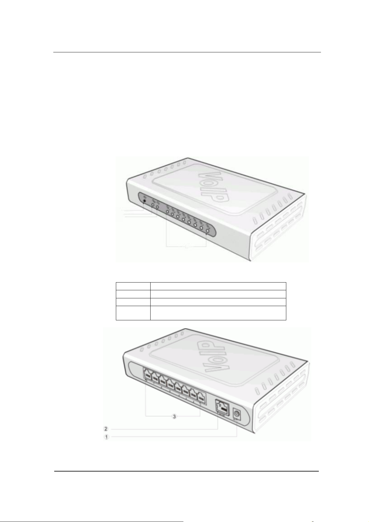
Figure 0-1 GT8 Front View
① Reset button (RST)
② Power indicator (PWR). If lit, power is on
③
④
Ethernet port indicator. If lit, it is in operation
FXS/FXO indicators. The port number is lit
when in use
Figure 0-2 GT8 Rear View
www.greatel.net - 9 -
Page 10

PRODUCT INTRODUCTION
Power plug-in
10/100 baseT Ethernet port
FXS/FXO ports, a total of 8
RJ11 Port Configuration
Model
Number
①
②
③
Table 0-1 GT8 Configuration Options
1 2 3 4 5 6 7 8
GT8-4S FXS1 FXS2 FXS3 FXS4 Null Null Null Null
GT8-8S FXS1 FXS1 FXS3 FXS4 FXS5 FXS6 FXS7 FXS8
GT8-/4 FXO1 FXO2 FXO3 FXO4 Null Null Null Null
GT8-4S/4 FXS1 FXS2 FXS3 FXS4 FXO1 FXO2 FXO3 FXO4
System Specifications
Table 0-2 GT8 Specification
Internal Memory 32MB
Flash Memory 4MB
On-hook Battery -56V
Off-hook Battery -24V
Ringing Voltage 60V
REN Equivalence
Loop Current = or > 21 mA
Loop Resistance Up to 188 Ω
Surge Voltage
Max Line Length 1500 m
Off-hook Detection Loop Start
Dialing DTMF
Input Voltage 12V DC
Input Current 1.5Amp (Max)
Power Consumption 15Watt (Max)
Operation Temperature 0 ~ 40°C
Non Operation
Temperature
Operation Humidity 5 ~ 95% (Non Condensed)
Dimension (H×L×W) 300x190x45 mm
Weight 800g
Specification
5 for short loop ( 1000 feet), 3 for long loop (5000
feet)
Level two surge protection. Can stand up to 1000V
(10/100uS) power surge
–25 ~ 70°C
www.greatel.net - 10 -
Page 11

PREPARATION FOR
INSTALLATION
To avoid any body injury and device damage, please read this
chapter carefully before the installation.
Safety Check
2
Please follow the safety guidelines when installing GT8.
• Keep away from wet group and heat
• Ensure safe use of electricity
• Ensure to connect all the interface cables correctly
Installation Environment
Temperature/Humidity
The GT8 installation room must maintain normal temperature and
humidity.
If the room temperature exceeds the specified maximum temperature,
it will shorten the live of the electrical insulation material. If the room
humidity exceeds the specified humidity, GT8 may experience
electrical static shock and shrinkage of electric insulation material in
the metal package. It may also cause metal corrosion. All these will
drastically shorten the life span of the GT8. It is strongly
recommended that user control the environmental temperature
www.greatel.net - 11 -
Page 12

Preparation for Installation
between 0 ~ 40ºC and humidity between 5% ~ 95% (none
condensing).
Dust Control and Air Flow
Dust falls on the GT8 might cause intermittent failure in electrical
connections. It may cause long term damage to GT8 will cause
equipment failure and shorten equipment life span. Therefore, GT8
needs to have ample air flow in front of the GT8 air intake and
outtake for proper heat exhaust.
Interference and Lightening Hazard
GT8 may experience various types of EMI hazards in operation and
its performance may be impacted. To reduce those hazards, it is
suggested that:
• Do not install GT8 close to high power wireless equipment,
RADAR transmission site, and high frequency high electric
current devices.
• GT8 comes with Level 2 lightening protection. Its operation site
requires Level 1 lightening protection.
• GT8 must have its own power source and should be electrical
interference free
• Ensure proper grounding
Installing GT8
When installing the GT8 please make sure GT8 is secured and has
ample space for air flow.
Inspecting GT8 and Its Accessories
After the installation preparation is completed, the shipping package
can be opened to examine all the items in the package. The list of
items for the GT8 is shown in Table 2 - 1.
Table 0-1 GT8 Basic Configuration and Accessories
www.greatel.net - 12 -
Page 13

Model Number Qty Description
Preparation for Installation
GT8-4S,GT8-8S,
GT8-/4, GT8-4S/4
1 Each GT8 may have 4 FXS ports, or 8
FXS ports, or 4 FXO ports, or 4
FXS/FXO ports. You need to examine
carefully to make sure what you receive
is what you paid for
MX-PWR10-V01-00 1 GT8 DC adaptor 12V 1.5A
MX-CBL00-0005 1 5 meter Ethernet cable, 1.5m in length
MX-CBL00-0011 1 GT8 power cord
Note:It is suggested that users carefully examine the content of
the shipping package according to the sales contract. If there is any
question or problem, please contact our customer service department.
www.greatel.net - 13 -
Page 14

INSTALLATION
Installing GT8
Since GT8 is small, you can put it to a clean and flat workspace.
Please make sure it is secured and has ample space for air flow.
Connecting the Cables
3
Connecting the Ethernet Port
GT8 has one 10/100 Base-T Ethernet port with RJ45 connector. It is
equipped with LED status display. Besides voice packet, this port can
also manage, maintain, and control the information flow.
The Ethernet Cable needs to be carefully made to ensure IP data
and voice quality. The following is the Ethernet cable making
scheme:
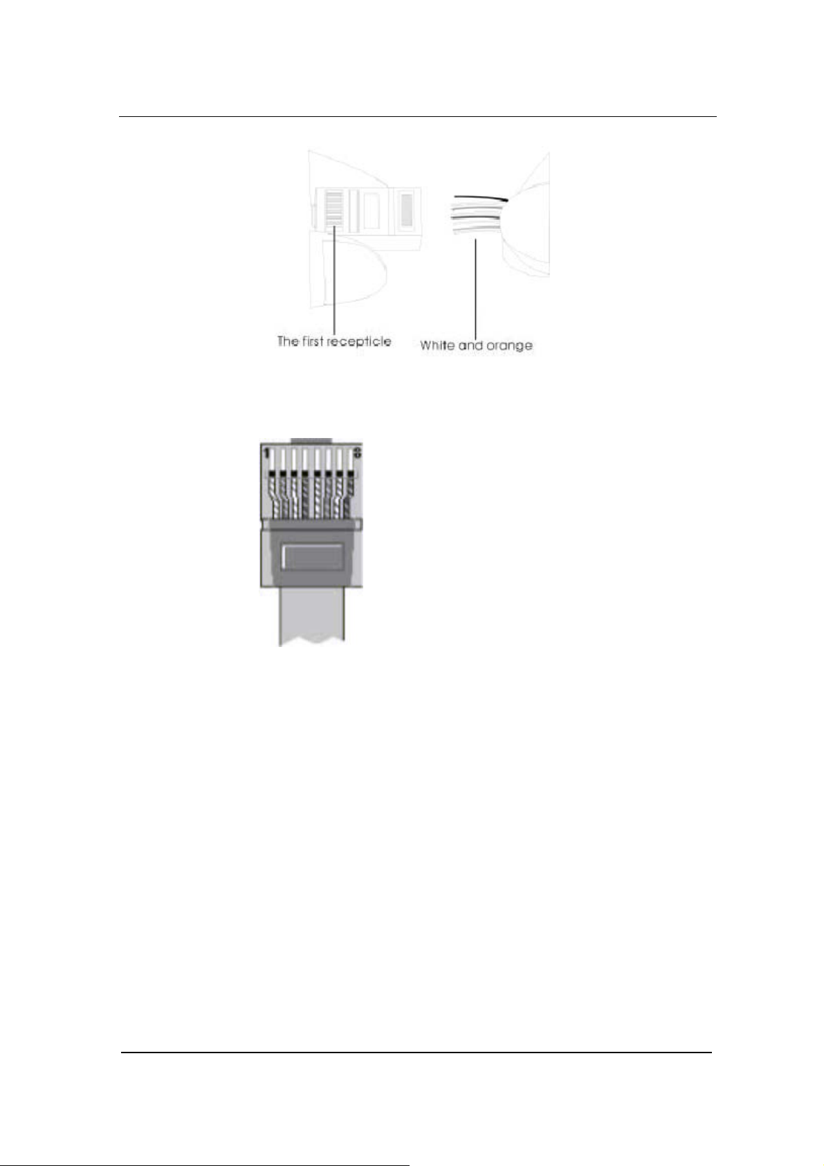
Step1: A user can use a proper cable peeling cutter to peel away
3cm skin of a CAT-5 cable. What is left is shown in Figure 3-
1.
www.greatel.net - 14 -
Page 15

Installation
Figure 0-1
Step2: Twisted pairs. Currently, the most commonly used standard
wiring scheme is EIA/TIA T568B shown in Figure 3-2. In the
wiring scheme, pin 1 and 2 are a pair, pin 3 and 6 are a pair,
pin 4 and 5 are a pair and pin 7 and 8 are a pair. According
to the Figure 3-2, twisted pairs line up with colors (1: white
orange,2: orange,3: white green,4:blue,5: white blue,
6:green,7: white brown,8: brown). It is specially noted that
the green and white green are separated by a pair of blue
wires. It is a common mistake to put green and white green
close together, which will result in interference and therefore
lower transmission efficiency.
Figure 0-2 T568B wire pairing scheme
Step3: After lining up wires to the correct pin positions, trim all the
twisted pairs with a cable cutter, leaving 15mm leads
exposed. Then follow Figure 3-3 by inserting wires to their
corresponding pin position in the plastic shell of RJ45
connector. Pin 1 will house white orange wire, etc.
www.greatel.net - 15 -
Page 16
Installation
Figure 0-3 RJ 45 Wiring
Step4: After wires have been properly inserted into RJ45 connector;
a cramping tool can secure the wires to the connector and
make connections to the metal pins as shown in Figure 3-4.
Figure 0-4 Finished RJ 45
Since this is a direct connection, the connector for the other end of
the cable can be made the same way using RJ45 connector.
After the Ethernet cable is ready, Connect one end of the cable to
GT8’s WAN port and the other end to a switch or router. Check the
Ethernet status display: light or flash means activity.
Connecting FXS Cable
GT8 have FXS ports that connect to phones.
Connect one end of the RJ11 cable to the GT8 FXS port, and
connect the other end to a phone, fax, or PBX.
Connecting FXO Cable
www.greatel.net - 16 -
Page 17

Installation
Certain GT8 products, like GT8-4 or GT8-4S/4, have FXO ports that
connect to PBX or PSTN.
Connect one end of the RJ11 cable to the GT8 FXO port, and
connect the other end to a PBX or PSTN line.
Connecting the Power Supply
Before plugging GT8 into the power outlet, it is suggested that triphase power outlet be used and grounding be properly connected.
Please follow the procedure when connecting to the power source:
Step1: Plug the DC head of the power adaptor into GT8’s DC input
socket.
Step2: Plug the AC head of the power adaptor into the power outlet
of 110V or 220V.
Step3: Check to see if the PWR LED indicator is lit. If PWR LED is lit,
everything is normal. If not, repeat Steps 1 to 2.
Note: If power up fails repeatedly, please contact GED technical
support. Do not attempt to open GT8 to fix any problems.
Final Checks after Installation
After installing GT8 and before it is powered on, please make sure of
the following:
• There is ample air space around GT8 for heat exhaustion.
• Power cord is standard and matches the required electric
voltage.
• Make sure the ports are connected to the right devices.
Note:It is very important to recheck all the installation work to
ensure GT8 to function properly and trouble free.
www.greatel.net - 17 -
Page 18

FUNCTION
DESCRIPTION
Registration
4
Step1: Power up the GT8. GT8 by default uses DHCP, and will
automatically detect an IP address; if you cannot get the IP
address (when you connect to the computer directly), use
default IP address “192.168.2.218”. After power up (when
customer line LCD stops flashing), if the gateway uses
MGCP protocol,it will tell the IP address to any first off-hook
user; if using SIP protocol, you can press “##” to get the IP
address through any customer line at any time.
Step2: Double click
connected to the same network as GT8.
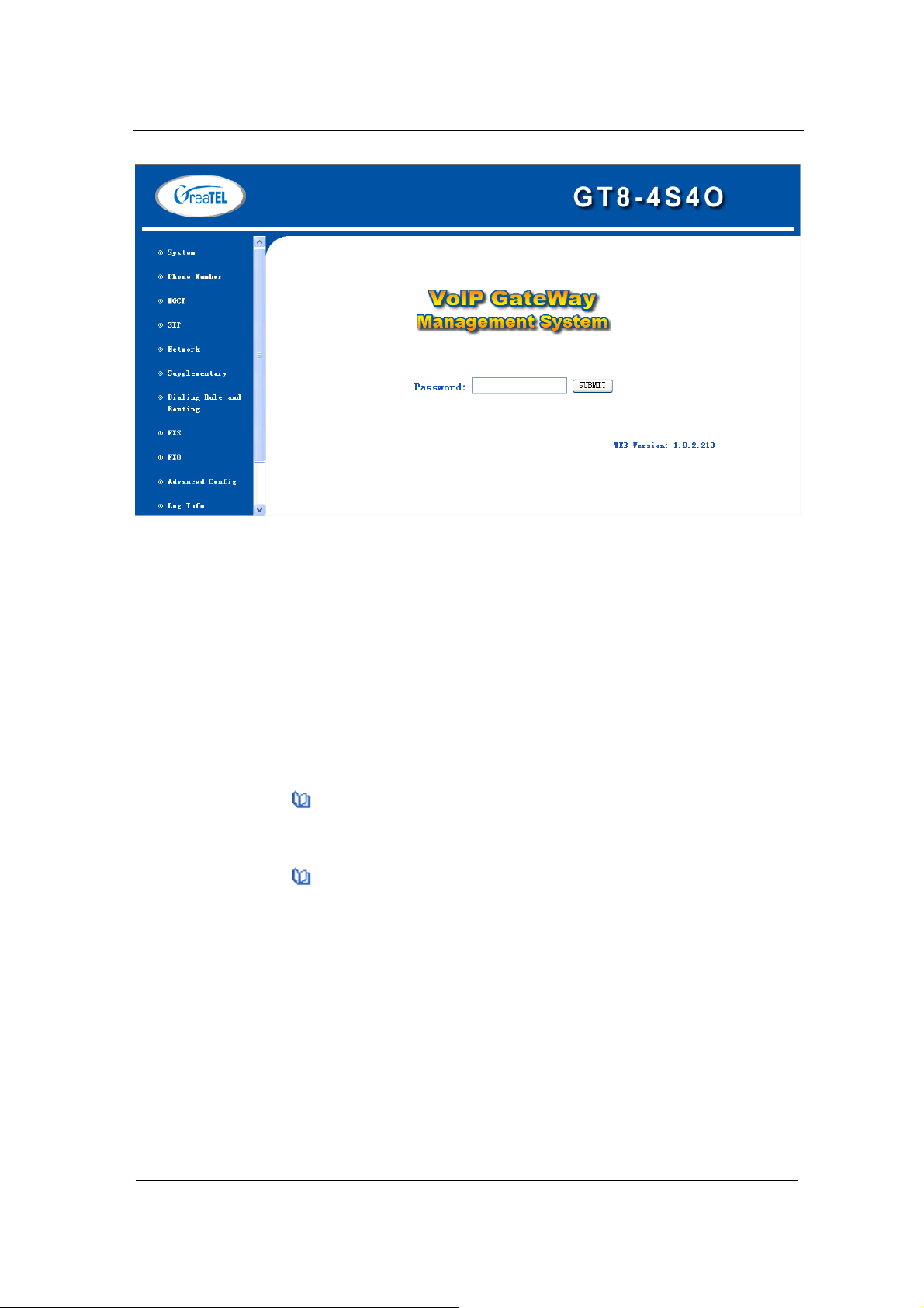
Step3: Type in GT8 IP address(for example:192.168.2.218)
as shown in Figure 4-1.
to open IE Explorer in the computer which is
,and the web interface will display
www.greatel.net - 18 -
Page 19
Function Description
Figure 0-1 VoIP Gateway System Configurations Interface
GT8 has two levels of management:the administrator level (default
password:GTadmin) and the operator level (default password:
operator). Administrator level has higher access privilege, and is
allowed to change password for all users at all levels. Operator level
has lower access privilege, and certain options are not available
including network configurations, password management and restore
factory default settings.
GT8 allows multiple users to log on at the same time. Only the first
user logged on with highest privilege is able to change configurations.
The rest can only monitor configurations.
Note1:After a user logs on, he/she will be automatically logged
off if there is no activities for more than 10 minutes. After that, a user
needs to log on again.
Note2:After complete configuration, a user must completely log
out instead of just closing the browser. This will elevate the access
level of the next logged on user so he/she will be able to change the
configurations.
Function Description of Most Used
Buttons
www.greatel.net - 19 -
Page 20
Function Description
At the bottom of each configuration page you will see two buttons:
Submit and Default.
• Submit: When you are done with configuration, click this button
once so that the configuration can be saved. After each
submission, you will be prompted by “Submission is successful.
Please restart the gateway!” You need to click OK to confirm the
action.
• Default: Click the button once to restore the factory default
setting for each parameter.
Note: Clicking this button only restore the defaults settings for the
current page. It is different from System Tools -> Restore Factory
Default in that the latter restore the default settings for the whole
system.
When the restoration is successful, you will be prompted by “The
settings are successfully restored. Please restart the gateway!” You
need to click OK to confirm the action.
System Configurations
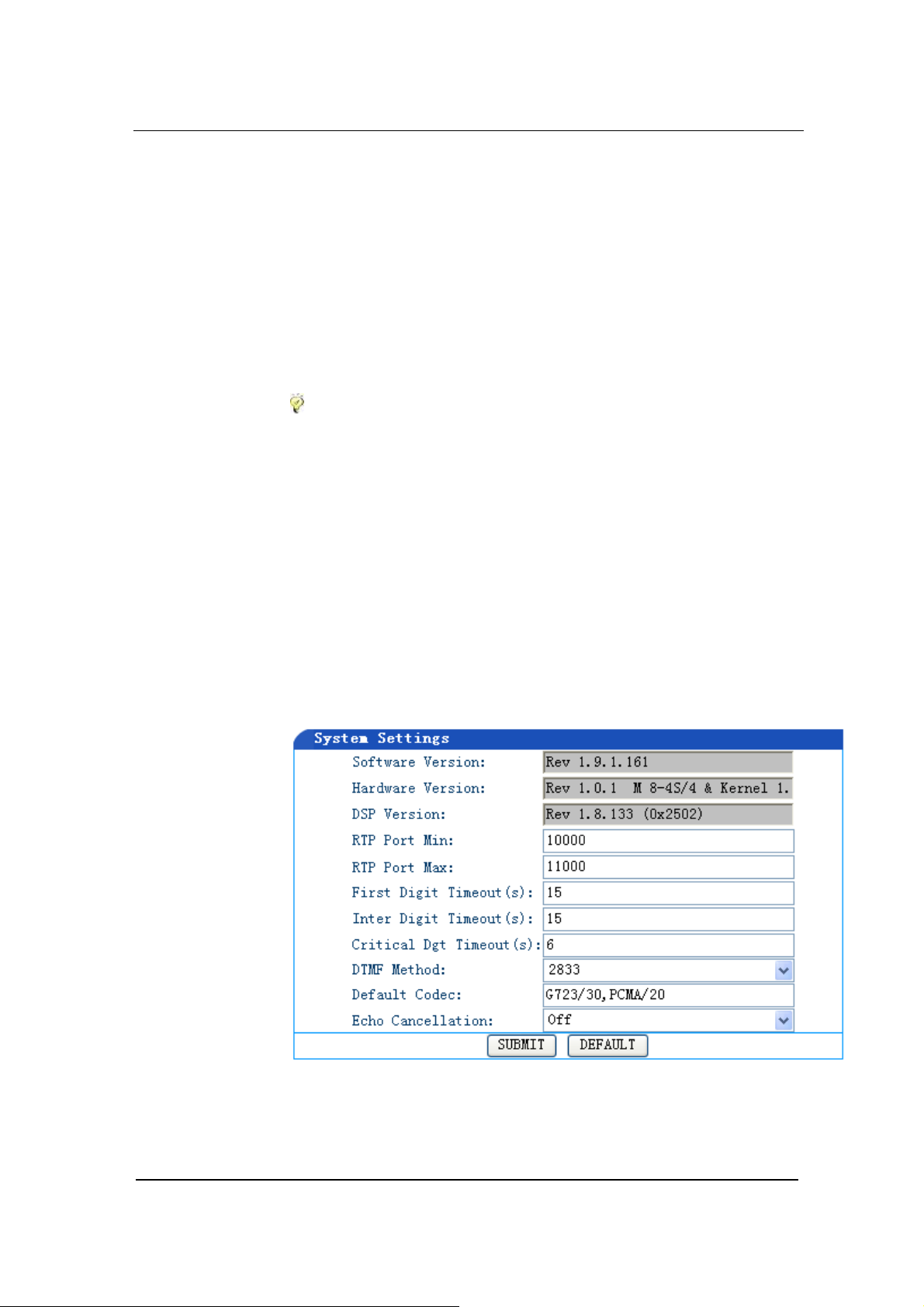
Click System Configuration link on the left of Figure 4-1, and you will
see what is shown in Figure 4-2.
Figure 0-2 System Configuration Interface
www.greatel.net - 20 -
Page 21

Function Description
Software Version
The Software Version field value is automatically detected. You do
not need to change this field.
Hardware Version
The Hardware Version field value is automatically detected. You do
not need to change this field.
DSP Version
The DSP Version field value is automatically detected. You do not
need to change this field.
RTP Port Min and Max
In the RTP Port Min field enter the minimum value of sending and
receiving RTP port.
you enter a value that is greater than 10000.
In the RTP Port Max field enter the maximum value of sending and
receiving RTP port.
you enter a value that equals “2 x number of lines + the minimum
value”.
Note: A VoIP call uses two RTP ports: one for RTP and the other
for RTCP. If GT8 has four lines (FXS) then the RTP port is set to
eight ports at least. If RTP has less than eight ports, four lines can
not be used at the same time. GT8 supports up to 8 FXS. So it is
highly recommended you set RTP to 16 ports. The default minimum
value is 10010~10030. You do not need to change it.
This is a required field. It is recommended that
This is a required field. It is recommended that
First Digit Timeout
In the First Digit Timeout field enter the time (in second) allowed for
the dialing of the first digit. When a line goes off-hook, if within the
time specified here the first digit has not been dialed, GT8 will treat
this as an abandoned call and will indicate to the caller to place the
phone on hook. The default value is 12 seconds.
www.greatel.net - 21 -
Page 22

Function Description
Inter Digit Timeout
In the Inter Digit Timeout field enter the time (in second) allowed for
the dialing of the middle digits. Counting from the last digit dialed, if
within the time specified here no digit has been dialed, the system
will send the dialed digits out. The default value is 12 second.
Critical Dgt Timeout
In the Critical Dgt Timeout field enter the time (in second) for
finished dialing.
This parameter is used in conjunction with x.T in
the dialing rule. After the first digit in the rule has been dialed, if within
the time specified here no digit follows, GT8 will send the dialed
number out. The default value is 5 seconds.
DTMF Mode
In the DTMF
1
Mode field select the transmission mode. This
parameter is used to set DTMF signal transmission mode. Options
are Audio mode, 2833 mode, and INFO mode. The default setting is
Audio mode.
a) Audio mode is a transparent transmit mode;
b) INFO mode is information transmit mode;
c) 2833 mode is a RTP data packet transmit mode.
Default Codec
In the Default codec2 field select the codec GT8 supports. GT8
support G729A/20, G723/30, PCMU/20, PCMA/20, GSM, iLBC codec
1
DTMF(Dual Tone Multi-Frequency)
In PSTN service, after a call is connected, user’s touch tone info is transmitted via DTMF, also known as
second dial tone information. It is widely used in intelligent network and value-added services.
• Audio: Voice data transparent transmit mode.
• 2833: A special RTP packet. PT field of the header indicates this is a DTMF packet. See FTC 2833 for
details.
• INFO: Optional way of DTMF transmission. As in SIP messages, use INFO to indicate a DTMF signal.
2
Voice CODEC
Also called a "voice codec" or "vocoder," it is a hardware circuit that converts the spoken word into digital
code and vice versa. It comprises the A/D and D/A conversion and compression technique. If music is
encoded with a speech codec, it will not sound as good when decoded at the other end. A speech codec is an
www.greatel.net - 22 -
Page 23
Function Description
as well as manifold encoding modes at the same time. Multiple
values are demarked by commas. When manifold encoding mode is
selected, the gateway will process the communication by selecting
the encoding mode front to back, which is supported by both sides.
Table 0-1 Codes supported
Codec supported
by GT8
G729A/20 G.729A 20
G723/30 G.723 30
PCMU/20 G.711 20
PCMA/20 G.711 20
iLBC/30 iLBC 30
GSM/20 GSM 20
Codec mode
Time interval of RTP packets
transmission(unit: ms)
Echo cancellation
In the Echo cancellation3 select on to invoke echo cancellation and
off to close echo cancellation. The manufacturer’s default is on. You
do not need to change it.
Set up the Phone Numbers
Click Phone Number link on the left of Figure 4-1, and you will see
what is shown in Figure 4-3:
audio codec designed for human voice. By analyzing vocal tract sounds, a recipe for rebuilding the sound at
the other end is sent rather than the soundwaves themselves. The speech codec is able to achieve a much
higher compression ratio, which results in a smaller amount of digital data for transmission. When telephones
were first digitized in the early 1960s, they generated digital streams of 64 Kbps. Since then, speech
CODECS have reduced voice to as little as 5 Kbps and less.
3
Echo Cancellation
The term echo cancellation is used in telephony to describe the process of removing echo from a voice
communication in order to improve voice quality on a telephone call. In addition to improving quality, this
process improves bandwidth savings achieved through silence suppression by preventing echo from traveling
across a network.
www.greatel.net - 23 -
Page 24
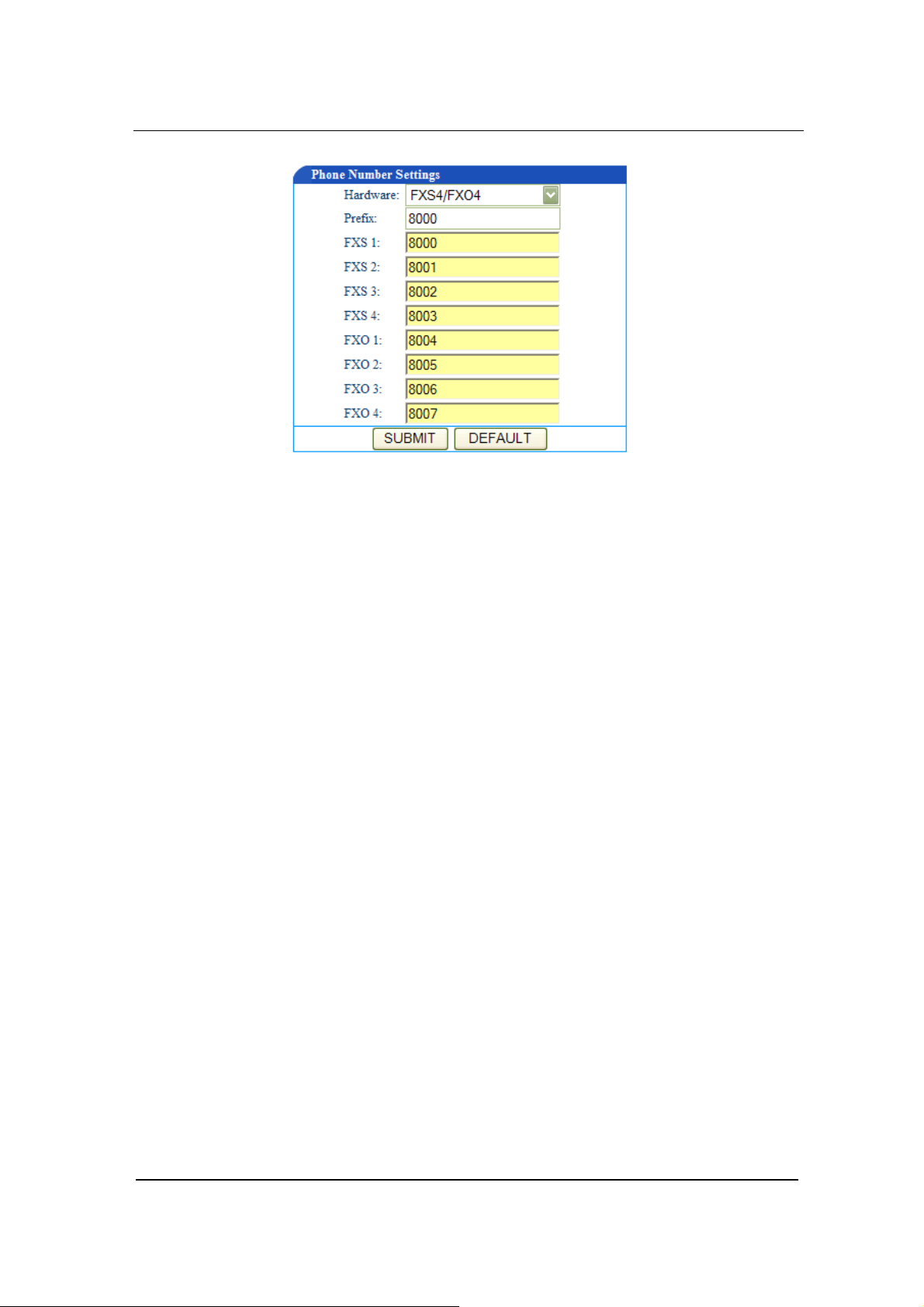
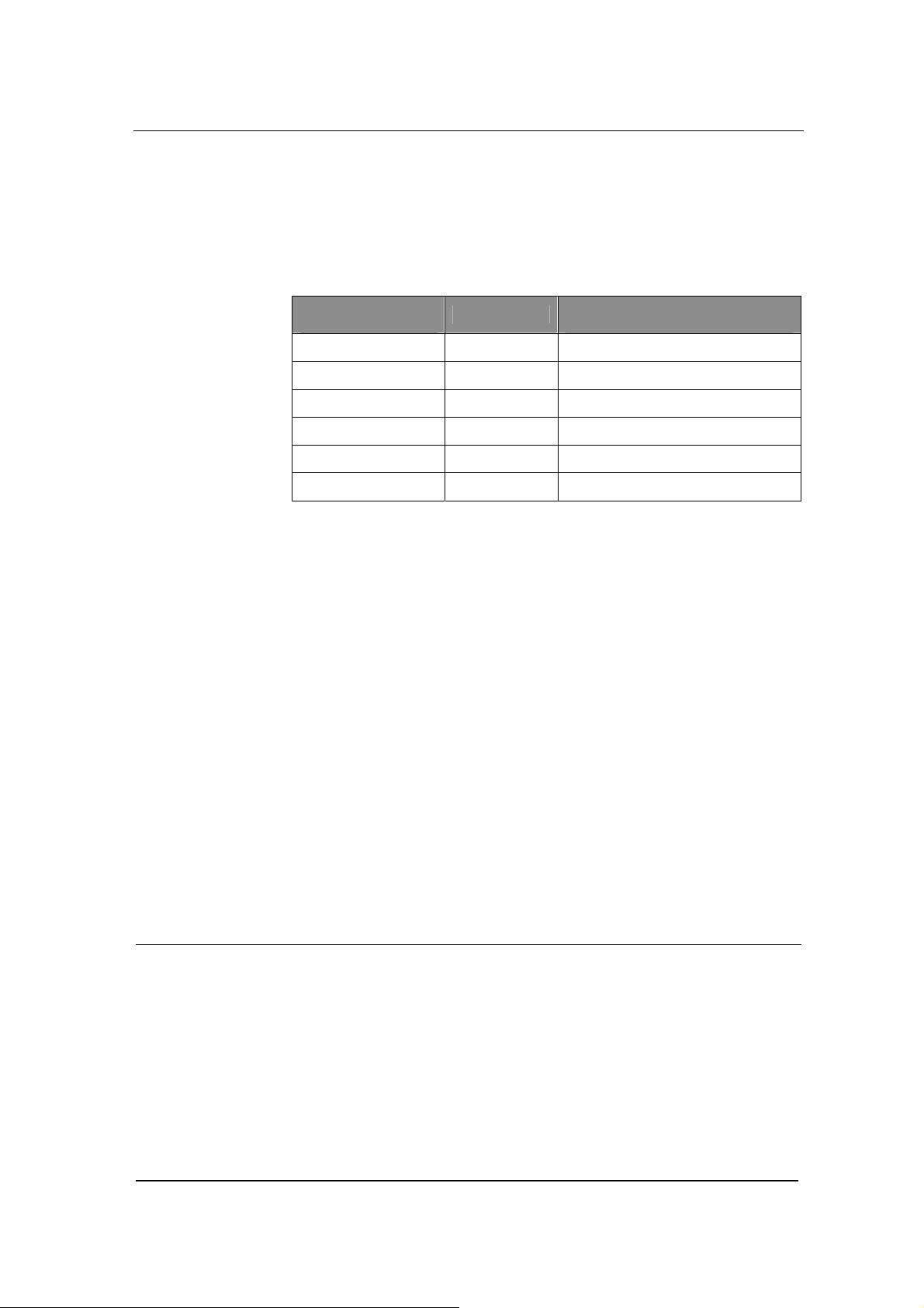
Figure 0-3 Phone Number setting screen
Hardware
Function Description
Leave the Hardware Settings field as it is. GT8 has more than one
model, and the model number is set through the software. This
parameter is already predefined by the manufacturer. You do not
need to change it.
Prefix
In the Prefix field enter a prefix number which is for fast setting for
serial number. You can leave it blank from FXS2 to FXO4. When
FXS1 uses this prefix number, FXS2 uses FXS1 number plus 1, and
so on and so forth.
When you set GT8 to MGCP gateway, the value of the prefix should
be set to aaln/0 or aaln/1. If MGCP call agent starts from “0”, then
use aaln/0; if MGCP call agent starts from”1”, then use aaln/1.
When you set GT8 to SIP gateway, the value of the prefix should be
the first number of the serial phone number which the registry server
assigns to the gateway. For example if the number of gateway is
2002007, then 200 should be entered in the Prefix field.
FXS(1~4)/ FXO(1~4)
www.greatel.net - 24 -
Page 25
Function Description
For the FXS lines, when the number is not a serial number or a serial
number that is not incrementing at order, you can manually enter the
number for each FXS line. This gives user more flexibility.
Under MGCP mode
You can set the phone numbers either like shown in Figure 4-4a or in
Figure 4-4b:
Figure 0-4 a Figure 0-4 b
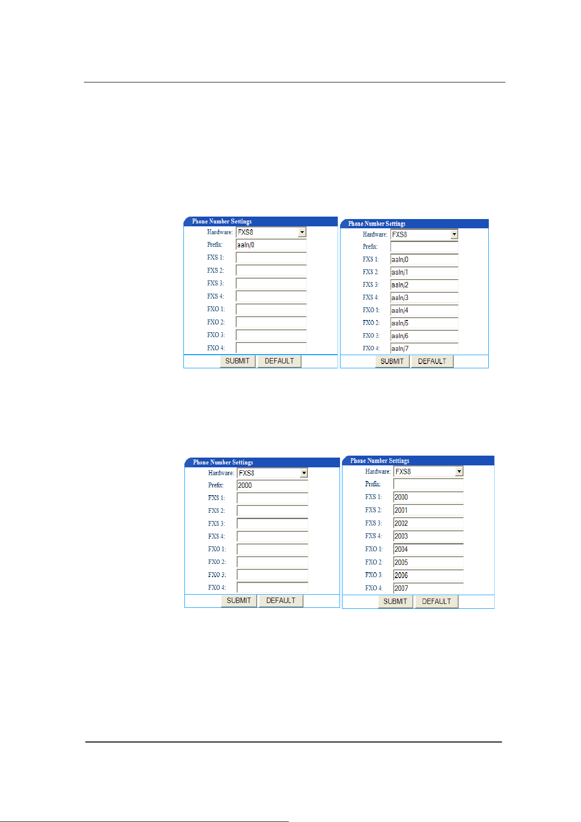
Under the SIP mode
You can set the phone numbers either like shown in Figure 4-5a or in
Figure 4-5b:
Figure 0-5a Figure 0-5 b
MGCP Setting
www.greatel.net - 25 -
Page 26
Function Description
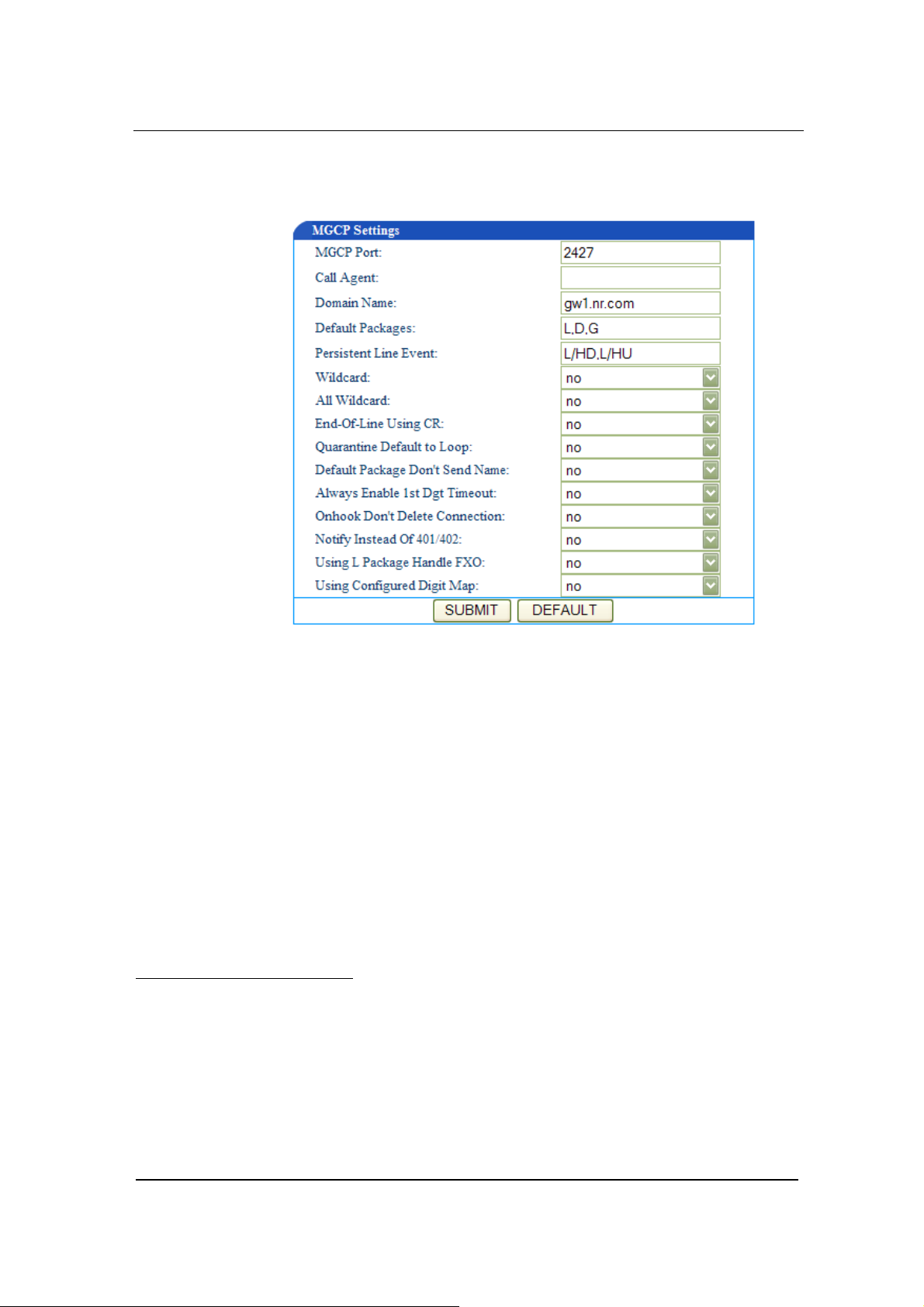
Click the MGCP Config link on the left of Figure 4-1. You will see
Figure 4-6.
Figure 0-6 MGCP setting screen
MGCP Port
In the MGCP Port field enter GT8 gateway MGCP port number
(example: 2427). You can use any port number as long as it is not
the same as other port numbers.
Call Agent
In the Call Agent4 field enter the call agent address and port number.
Address and port number should be separated by :. Address could
4
Call Agent
Call Agent, also known as Media Gateway Controller, controls the Media Gateway. In MGCP, a call agent
primarily handles all the call processing by linking with the IP network through constant communications
with an IP signaling device, for example an SIP Server or an H.323 gatekeeper.
Call Agent is comprised of the call control "intelligence" and a media gateway boasting the media functions,
for example conversion from TDM voice to Voice over IP.
Media Gateways feature endpoints for the Call Agent to create and manage media sessions with other
multimedia endpoints. Endpoints are sources and/or sinks of data that can be physical or virtual. For creating
www.greatel.net - 26 -
Page 27

Function Description
be IP address or domain name. If you use domain name, you should
invoke DNS service and set parameter of DNS server in the Network
Config page. A complete sample configuration is like this:
202.202.2.202:2727; callagent.com:2727.
Domain Name
In the Domain Name field enter the internet address or the IP
address.
Default Packages
In the Default Packages field enter all default packages. Use comma
to separate each package. The default setting is L,D,G, which means
Line Package, DTMF Package, and Generic Media Package.
Persistent Line Event
In the Persistent Line Event field enter all types of persistent line
event. Use comma to separate each line event. The gateway will
report to call agent when it handles an event. The default setting is
L/HD, L/HU, and L/HF. L/HD means off-hook; L/HU means on-hook;
and L/HF means hookflash.
Wildcard
In the Wildcard field select yes or no to indicate if GT8 will put the
fixed prefix when it registers (such as :aaln/*).
All Wildcard
physical endpoints, hardware installation is needed while virtual endpoint can be created using available
software.
Call Agents come with the capability of creating new connections, or modify an existing connection.
Generally, a media gateway is a network element which provides conversion between the data packets carried
over the Internet or other packet networks and the voice signals carried by telephone lines. The Call Agent
provides instructions to the endpoints to check for any events and - if there is any - create signals. The
endpoints are designed in such a way as to automatically communicate changes in service state to the Call
Agent. The Call Agent can audit endpoints and the connections on endpoints.
www.greatel.net - 27 -
Page 28

Function Description
In the All Wildcard field select yes or no to indicate if GT8 will put
the fixed prefix when it registers (such as :*). If Wildcard and All
Wildcard are yes, the gateway will deal with all wildcard.
End-Of-Line Using
In the End-Of-Line Using CR field select yes or no to indicate if GT8
will use CR as line stop symbol when sending messages. If set to no,
CRLF will be used.
Quarantine Default to Loop
In the Quarantine Default to Loop field select yes or no to indicate
how GT8 will handle events when there is no response for
requirements. If set to yes, gateway will report continuously all
events of this requirements when it receive a requirement; if set to no,
gateway will response only once for each requirement.
Default Package Don’t Send Name
In the Default Package Don’t Send Name field select yes or no. If
set to yes, the gateway will reply to the default package without a
package name; if set to no it will reply to the default package with a
package name.
Always Enable 1st Digit Timeout
In the Always Enable 1st Digit Timeout field select yes or no to
indicate how GT8 will handle events when there is no timeout during
the required time. If set to yes, the gateway will report timeout
according to the settings when the caller does not dial a phone
number after going off-hook.
Onhook don’t Delete Connection
In the Onhook don’t Delete Connection field select yes or no. If
you select yes, the gateway will delete the connection when the
caller does not go on-hook; if you select no the gateway will wait for
the call agent to delete the connection.
www.greatel.net - 28 -
Page 29

Function Description
Notify Instead of 401/402
In the Notify Instead of 401/4025 select yes or no. If you select yes,
the gateway will use notification message instead of 401/402
message.
Using L Package Handle FXO
In the Using L Package Handle FXO field select yes or no. If you
select yes, the gateway will treat FXO as FXS; if you select no, it will
handle FXO and FXS in different ways.
Using Configured Digit Map
In the Using Configured Digit Map field select yes or no. If you
select yes, the gateway will invoke the dialing rule; if you select no, it
will use the rule of soft-switch.
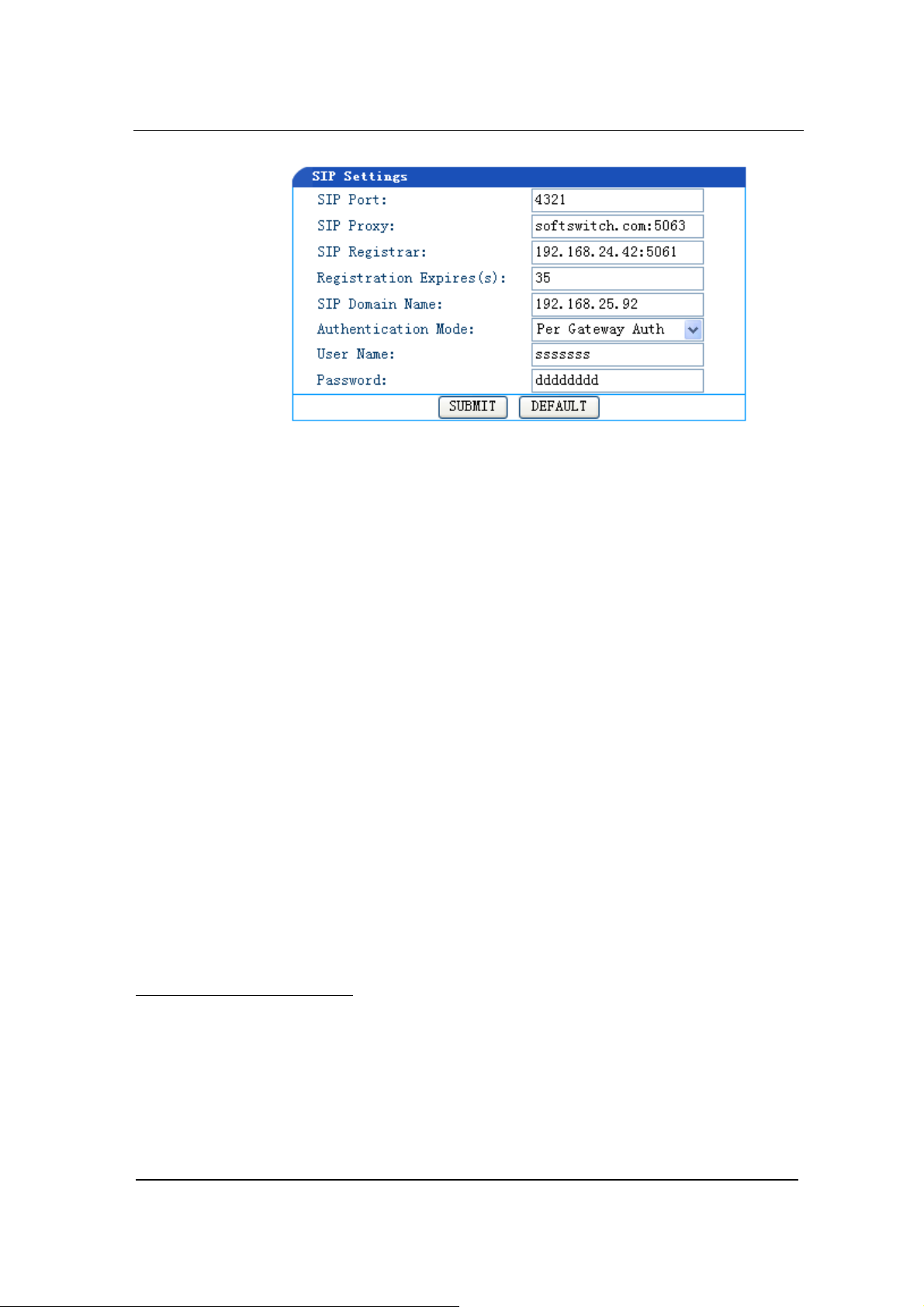
SIP Setting
Click the SIP6 link on the left of Figure 4-1,and the SIP Settings
screen displays.
5
401/402: Response Code.
6
SIP (Session Initiation Protocol)
Session Initiation Protocol (SIP) is the Internet Engineering Task Force's (IETF's) standard for multimedia
conferencing over IP. SIP is an ASCII-based, application-layer control protocol (defined in RFC 2543) that
can be used to establish, maintain, and terminate calls between two or more end points.
Like other VoIP protocols, SIP is designed to address the functions of signaling and session management
within a packet telephony network. Signaling allows call information to be carried across network boundaries.
Session management provides the ability to control the attributes of an end-to-end call.
www.greatel.net - 29 -
Page 30
Function Description
Figure 0-7 SIP settings screen
SIP Port
In the SIP Port field enter the number of SIP local port. The default
value is 5060. Local port number could be set at will, as long as it
doesn’t conflict with the other port numbers in the system.
SIP Proxy
In the SIP Proxy field enter the address and port number of the
Proxy. The address and port number is separated by a colon. The
address can be in either IP address form or domain name form.
When adopting domain name form, it is necessary to invoke DNS
service in the “Network Setting” page and set the parameter of DNS
server. The complete and valid setting is as following:
201.30.170.38:5060 and softswitch.com:5060.
SIP Registrar
In the SIP Registrar7 field enter the address and port number of the
SIP Registrar The address and port number are separated by a colon.
Like other VoIP protocols, SIP is designed to address the functions of signaling and session management
within a packet telephony network. Signaling allows call information to be carried across network boundaries.
Session management provides the ability to control the attributes of an end-to-end call.
7
Registrar
When a client powers on, it will tell network its IP address in order to be found. We call this procedure
“register”. The server that accepts this request is called “registrar”.
www.greatel.net - 30 -
Page 31

Function Description
The address can be in either IP address form or domain name form.
When adopting domain name form, it is necessary to invoke DNS
service in the “Network Setting” page and set the parameter of DNS
server. The complete and valid setting is as following:
201.30.170.38:5060 and regster.com:5060.
Registration Expires(s)
In the Registration Expires(s) 8 field enter the valid time (in second)
for SIP re-registration. The default value is 30 seconds.
SIP Domain Name
In the SIP Domain Name field enter the SIP domain name. If the
field is left empty, GT8 will use the address of the Proxy as the
domain name. It is recommended that you do not use a private
network IP address in this field.
Authentication Mode
In the Authentication Mode field use the drop down menu to make a
selection. Per Endpoint means to register and authenticate wholly
according to each individual line; Per Gateway Reg means to
register and authenticate wholly according to gateway; Per Gateway
Auth means to register according to each individual line, and to
authenticate wholly according to gateway.
User Name
Set the User Name field if registered as Per Gateway Reg or Per
Gateway Auth; if registered as Per Endpoint, do not set this
parameter.
Password
8
Registration Expires
In order to control client side, every register message has a certain stored period. If the message is modified in
that period, which mean it works for user otherwise Registrar will consider the message is not useful any
more, so it will be deleted.
www.greatel.net - 31 -
Page 32

Function Description
In the Password field enter soft-switch authentication password,
which can be digits or characters. The password is case sensitive. If
registered as Per Gateway Reg or Per Gateway Auth you need to
set this parameter; if registered as Per Endpoint, you do not need to
set this parameter.
Network Configuration
Click the Network Config link on the left side of Figure 4-1. The
Network Settings screen displays:
Figure 0-8 Network Settings Screen
Hostname
www.greatel.net - 32 -
Page 33

Function Description
In the Hostname field, enter the GT8 gateway name. You can use
your own naming convention according to your network setup.
Gateway IP Address
In the Gateway IP Address field enter the default GT8 IP address if
you have not enabled DHCP services.
DHCP
In the DHCP field select on or off to indicate to use DHCP or not to
assign IP addresses and other network settings.
Ethernet IP Address
In the Host IP Address field enter the GT8 Ethernet port number if
you have not enabled DHCP services. If you have enabled DHCP
services, this field will display the IP address that DHCP captures.
Subnet Mask
In the Subnet Mask field enter the subnet mask address you obtain
from your system administrator or from your ISP if you have not
enabled DHCP services.
Hardware Address
Leave the Hardware Address as it is. You are not allowed to change
it.
DNS
In the DNS field select on or off to indicate to turn on DNS services or
not. You need to turn on DNS service when you use the domain
name as the proxy server address or registration server address in
your MGCP or SIP configuration.
www.greatel.net - 33 -
Page 34

Function Description
DNS Primary Server
In the DNS Primary Server field enter GT8 primary DNS server
address if you have turned on DNS services.
DNS Alternate Server
In the DNS Alternate Server field enter alternate GT8 DNS server
address if you have turned on DNS services.
PPPoE
In the PPPoE field select on or off to indicate to use PPPoE service
or not.
• If you selected on in Step 11, you need to enter your user name
in the PPPoE Username field.
• If you selected on in Step 11, you need to enter your password
in the PPPoE Password field.
Time Primary Server
In Time Primary Server field enter the IP address of your primary
Time server.
Time Alternate Server
In Time Alternate Server field enter the IP address of your alternate
Time server.
Timeout
In the Timeout field enter the time (in minute) allowed to locate the
Time server. If the server is not located within the time allowed, GT8
will try to locate it again.
Interval
www.greatel.net - 34 -
Page 35

Function Description
In the Interval field, enter the time interval (in minute) at which GT8
will synchronize its time with the Time server.
Time Zone
In Time Zone field select the GT8 location.
The following is the options are available for this parameter: Midway,
Honolulu, Anchorage, Tijuana, Denver, Mexico_City, Indianapolis,
Glace_Bay, Buenos_Aires, South_Georgia, Cape_Verde, London,
Amsterdam, Cairo, Moscow, Muscat, Karachi, Almaty, Bangkok,
Beijing, Tokyo, Canberra, Magadan, Auckland, Newfoundland,
Tehran, Kabul, Calcutta, Adelaide
Supplementary Features
The features in this section are enabled only when using SIP
Protocol. The same features are provided by the proxy server when
using MGCP Protocol. There is no need for configuration.
Setting up the Feature Keys
Click the Supplementary link on the left side of Figure 4-1. Then
click Feature Code. The Feature Code Settings screen displays (see
Figure 4-9). You can set up all the supplementary feature keys from
here. The general rule is *xx for enable (i.e. dial the * key plus any
two digits that represent the feature) and #xx for disable (i.e. dial the
# key plus any two digits that represent the feature). The screen
shows all the features with their default values. You can replace the
default with any numbers you like.
www.greatel.net - 35 -
Page 36

Function Description
Figure 0-9 Feature Code Setting Screen
Enable All Forwarding
This allows the customer to define and enable forwarding all calls
function. The default function key is *60. To use this feature the
customer must first sign up for the call forwarding service.
Disable All Forwarding
This feature allows the customer to disable the All Forwarding service.
For example:
To forward all calls to phone number 5614888888, the enabling key
is *60. The disenabling key is #60.
a) To enable:
Go off hook
→ Dial *60 → Upon hearing the dialing tone, enter
5618888888 → Dial # to end → Go on hook.
b) To verify:
www.greatel.net - 36 -
Page 37

Function Description
Go off hook → Dial *60 → Upon hearing the forwarded number
dial # to end → Go on hook.
c) To disable:
Go off hook
→ Dial #60 → Go on hook.
Enable Busy Forwarding
This allows the customer to enable the forwarding feature when the
line is busy. The default function key is *61. To use this feature the
customer must first sign up for the call forwarding service.
Disable Busy Forwarding
This allows the customer to disable Busy Forwarding function. The
default function key is #61.
For example:
To forward all the calls when the line is busy to phone number
5614601688, the enabling key is *61. The disenabling key is #61.
a) To enable:
Go off hook
→ Dial *61 → Upon hearing the dialing tone, enter
5614601888 → Dial # to end → Go on hook.
b) To verify:
Go off hook
→ Dial *61 → Upon hearing the forwarded number
dial # to end → Go on hook.
c) To disable:
Go off hook
→ Dial #61 → Go on hook.
Enable No Answer Forwarding
This allows the customer to define and enable the forwarding feature
when the line is busy. To use this feature the customer must first sign
up for the call forwarding service.
Disable No Answer Forwarding
The default function key for this feature is #62.
For example:
To forward calls to 5618881680 when nobody is answering the calls,
the enable key is *62, and the disable key is #62.
a) To enable,
www.greatel.net - 37 -
Page 38

Function Description
Go off hook → Dial *62 → On hearing the dialing tone, dial
5618881680 → Dial # to end → Go on hook.
b) To verify,
Go off hook
→ Dial *62 → On hearing the forwarded number go
on hook.
c) To disable,
Go off hook
→ Dial #62 → Go on hook.
Cancel Call Waiting
This allows the customer to disable the call waiting function when a
call is in progress to avoid interruption. The default function key is *64.
This feature works for only one call. To completely remove call
waiting, please refer to section 4.9.
Enable Do Not Disturb
When this feature is enabled, the customer will not hear the ringing
tone when a call comes in. The caller will hear busy tones. The
default function key is *72. To use this feature, the customer needs to
first sign up for the Do Not Disturb services. Please refer to section
4.9.
Disable Do Not Disturb
This will restore the normal call handling. The default function key is
#72.
Set Speed Dial
The default function key is *74. This allows the customer to use a
two-digit code (from 20 to 49) for dialing the complete digits. To use
this feature the customer needs to sign up for speed dial services.
Speed Dial Prefix
This defined the identifiers for speed dial. The default function key is
**. Before using the speed dial, the customer must first dial these two
digits.
For example:
The speed dial code for phone number 5613221680 is 20, and the
speed dial prefix is ** .
a) To enable speed dial,
www.greatel.net - 38 -
Page 39

Function Description
Go off hook → Dial *74 → On hearing the dialing tone, dial 20
plus 5613221680 → Dial # to end.
b) To verify,
Go off hook
→ Dial *74 → On hearing the dialing tone, dial 20
plus * to end → On hearing the complete digits, go on hook.
c) To use the speed dialing,
Go off hook
→ Dial ** plus 20.
d) To disenable,
Go off hook
→ Dial *74 → On hearing the dialing tone, dial 20
plus # to end.
Listen IP Address
This allows the customer to hear the IP address of his phone line.
The default function key is ##.
Enable Line Search
This allows the customer to hear the phone number of this his phone
line. The default function key is #00.
Listen to PPPoE IP Address
This allows the customer to hear the gateway PPPoE IP address.
The default function key is #01.
Enable Fashion Ring
This allows the customer to set the ring tones to his liking. The
default function key is *80.
Cancel Fashion Ring
This restores the ringing tone to normal. The default function key is
#80.
For example:
Use the default function key for enabling distinctive ring. Set the
distinctive ring ID number from 01 (must have two digits).
a) To enable,
Go off hook
Go on hook.
→ Dial *80 → On hearing the dialing tone, dial 01 →
www.greatel.net - 39 -
Page 40

b) To verify,
Function Description
Go off hook
→ Dial *80 → On hearing the distinctive ringing go on
hook.
c) To disenable,
Go off hook
→ Dial #80 → Go on hook.
Listen Fashion Ring
The default function key is *88.
To use:
Go off hook
→ Dial *88
→ Dial distinctive ring ID number 01
→ Dial distinctive ring ID number 05
→ Dial distinctive ring ID number 12
→ Dial distinctive ring ID number 34
→ ... ...
→ Go on hook.
→ Listen to the ring tones
→ Listen to the ring tones
→ Listen to the ring tones
→ Listen to the ring tones
Set up All Forward
Click the Supplementary link on the left side of Figure 4-1. Then
select Set Forward All. You will see All Forward Settings screen, as
shown in Figure 4-10:
Figure 0-10 All Forward Settings Screen
This screen is used to enter the forwarding numbers for All Forward
feature subscribers or to display during operation the forwarding
numbers entered by the end users. Calls will be forwarded to those
numbers only when the end users sign up for the Call Forwarding
services and when they enable this feature using the function key.
www.greatel.net - 40 -
Page 41

Function Description
Set up Busy Forward
Click the Supplementary link on the left side of Figure 4-1. Then
click Busy Forward. The Busy Forward Settings screen displays, as
shown in Figure 4-11:
Figure 0-11 Busy Forward Settings Screen
This screen is used to enter forwarding numbers for Busy Forward
feature subscribers or to display during operation the forwarding
numbers entered by the end users. Calls that come on busy lines will
be forwarded to those numbers only when the end users sign up for
the Call Forwarding services and when they enable this feature using
the function key.
Set up No Answer Forward
Click the Supplementary link on the left side of Figure 4-1. Then
click No Answer Forward. The No Answer Forward Settings screen
displays, as shown in Figure 4-12:
Figure 0-12 No Answer Forward Setting Screen
This screen is used to enter forwarding numbers for No Answer
Forward feature subscribers or to display during operation the
forwarding numbers entered by the end users. Calls that get no
answers will be forwarded to those numbers only when the end users
www.greatel.net - 41 -
Page 42

Function Description
sign up for the Call Forwarding services and when they enable this
feature using the function key.
Set up Fashion Ring
Click the Supplementary link on the left side of Figure 4-1. Then
click Fashion Ring. The Fashion Ring Settings screen displays, as
shown in Figure 4-13:
Figure 0-13 Fashion Ring Settings Screen
This screen is used to enter distinctive ring serial numbers for
Fashion Ring feature subscribers or to display during operation the
fashion ring numbers entered by the end users. End users that have
singed up for Fashion Ring services and have enabled the feature
using the function key will hear the distinctive rings.
Set up Hotline
Click the Supplementary link on the left side of Figure 4-1. Then
click Hotline. The Hotline Settings screen displays, as shown in
Figure 4-14:
Figure 0-14 Hotline Settings Screen
www.greatel.net - 42 -
Page 43

Function Description
This screen is used to enter hotline numbers for Hotline feature
subscribers. End users that have singed up for Hotline or Delay
Hotline services have access to this feature.
For example, FXS Line 1’s hotline number is set up as1680. If the
end user of Line 1 has signed up for Hotline services, when he goes
off hook the phone will automatically dial 1680. However hotline
users cannot dial any other numbers. If the end user of Line 1 also
signed up for Delay Hotline services, within six seconds of going off
hook, if no other number is dialed, the hotline number 1680 will be
dialed; if another number is dialed within six seconds, then this call is
treated as a normal call. Hotline function will be ignored.
Dialing Plan and Routing Table
Set up the Dialing Plan
Click the Dialing Plan link on the left side of Figure 4-1. Then click
Digit Map. The Digit Map Rules screen displays, as shown in Figure
4-15:
Figure 0-15 Digit Map Rules Screen
Digit Map is used to determine if the digits received are the complete
numbers dialed, so that the dialing process will terminate and the
digits will be sent out in a speedy way. This can shorten the
connection time for calls.
www.greatel.net - 43 -
Page 44

Function Description
GT8 has in its default Dialing Plan most of the domestic digit map
rules. You do not have to re-configure them. You can add new rules
when necessary. The following is an illustration of the common rules:
Table 0-2 Common Digit Map Rules
X
.
##
x.T
x.#
*xx
#xx
[2-8]xxxxxx
02xxxxxxxxx
013xxxxxxxxx
13xxxxxxxxx
11x
9xxxx
17911
Any single digit between numbers 0 to 9.
any multiple digit between numbers 0 to 9.
terminate dialing after receiving two digits. ## is GT8
gateway’s default function key for listening to the IP
address.
The gateway will check a number of any lengths that is
composed of any number between 0 and 9. If no new
digits are received within the “dialing finish” time, the
gateway will send out the detected number.
a number of any length that starts with any number
between 0 and 9. If the end user dials # right after the
number, GT8 will stop number reception and send out
the number before #.
terminate dialing after receiving * plus any two digits.
*xx is mainly used to enable the supplementary
services (such as Distinctive Ring, Do Not Disturb, and
Call Forwarding).
end dialing after receiving # plus any two digits. #xx is
mainly used to disable the supplementary services.
a seven-digit number that starts with any number
between 2 and 8. This is used to terminate local call
dialing.
an 11-digit number that starts with 02. This is used to
terminate long distance call dialing that starts with 02.
a 12-digit number that starts with 013. This is used to
terminate long distance cellular calls that start with 013.
an 11-digit number that starts with 13. This is used to
terminate local cellular calls that start with 13.
a three-digit number that starts with 11. This is used to
terminate emergency calls.
a five-digit number that starts with 9. This is used to
terminate special service calls
send out the number right after receiving 17911. This
serves as an example of terminating a special number.
Set up the Routing Table
Click the Dialing Plan link on the left side of Figure 4-1. Then click
Route Table. The Route Table screen displays, as shown in Figure
4-16:
www.greatel.net - 44 -
Page 45

Function Description
Figure 0-16 Routing Table Screen
Routing table serves two main functions: number swapping and route
exchange. The table is executed from top to bottom. Number
swapping always has advantage over route exchange. A routing
table can have a maximum of 100 entries.
Note: The routing table is empty by default. All the calls go to the
SIP Proxy server, and are routed by this server.
1. Number Swapping
One phone number consists of three sections: Origination,
Number, and Action.
• Origination can have the following values: IP, FXS, and
FXO. IP can be any IP address, a specified IP address, and
a specified IP address plus the port number. FXS and FXO
can be a specific line number (for example FXS1, FXO2 or
FXS 1 – 2, etc.)
• Number can be the calling number, or the called number.
Default is the called number. If it is the calling number, add
CPN before the number as the identifier. The number can
use any digit between 1 to 9, *, ., #, X etc, just like the digit
map. The common rules are:
Numbers, such as 114, 68640585
The beginning digits of a number, such as 61xxxx, or
612x, or 61
Expressions such as 268[0-1, 3-9], which indicates a
number that starts with 268 and followed by any
number from 0 to 1 or 3 to 9
The search for a matching number follows the
principle of “shortest and quickest”. For example, x
www.greatel.net - 45 -
Page 46

Function Description
equals all numbers; xx equals all two-digit numbers;
12x equals all three-digit numbers that start with 12
• Action defines the processing method and the actual
information that has been processed. It can have three
values:
KEEP: Keep means to keep the number. Another
number goes after it. If that number is positive, it
means to count the number from the front; if the
number is negative, it means to count the number
from the backward. For example,
FXS 02168640585 KEEP -8.
This means to keep the last eight digits of this called
number from the FXS, that is 68640585.
REMOVE: Remove means to remove the number.
Another number goes after it. If that number is
positive, it means to count the number from the front;
if the number is negative, it means to count the
number from the backward. For example,
FXS 021 REMOVE 3.
This means to remove 021 if the called number from
an FXS starts with 021
ADD: Add means to add digits before or after the
called number. Another number goes after it. If that
number is positive, it means to add before the
number; if the number is negative, it means to add
after the number. For example,
FXS1 CPNX ADD 021
FXS2 CPNX ADD 010
This means to add 021 to all the CNP from FXS1; to
add 010 to all the CPN from FXS2.
Another example:
FXS CPN6120 ADD -8888,
meaning to add 8888 to CPN from the FXS that start
with 6120
REPLACE: means to replace the number, followed
by the number to be replaced to. For example, FXS
CPN88 REPLACE 2682000, meaning for a CPN
www.greatel.net - 46 -
Page 47

Function Description
from an FXS that starts with 88, replace it with
2682000
REPLACE:
cross replacement, means to replace the
number corresponding to the called number or calling
number
For example,
FXS 12345 REPLACE CPN-1/8621
This means remove the last one digit then add 8621
at the end of the calling number corresponding to the
called number from an FXS that starts with 12345
FXS CPN13 REPLACE CDPN0/0
This means add 0 at the head of the called number
corresponding to the calling number from an FXS
that starts with 13.
FXS 12345 REPLACE CPN1/
This means remove one digit at the head of the
calling number corresponding to the called number
from an FXS that starts with 12345
FXS 12345 REPLACE CPN/5678
This means add 5678 at the head of the calling
number corresponding to the called number from an
FXS that starts with 12345
FXS 12345 REPLACE CPN-/5678
This means add 5678 at the end of the calling
number corresponding to the called number from an
FXS that starts with 12345
Notes:
CPN and CDPN: the appointed digit stream.
If CPN and CDPN behind REPLACE, the CPN
means calling number and the CDPN means
called number.
If the number before REPLACE, CPN means
calling number, the called number is indicated
with digits directly.
If no “/”, means replace all.
“-“: means the end of the number.
www.greatel.net - 47 -
Page 48

Function Description
CPNn: n means how many digits will be
replaced.
If n is 0, means insert
If n larger than the quantity of whole digits,
means replace all.
If there is no number at the end of “/”, means
remove
If there is no number at the front of “/”, means
insert, the gateway will insert 0 automatically.
END: means to terminate certain number processing.
When performing number swapping from top to
bottom, if END or ROUTE is present, then end
number swapping. For example,
FXS 12345 ADD -8001
FXS 12345 REMOVE 4
FXS 12345 END
This means for the called number from an FXS that
starts with 12345, first add 8001 at the end of the
number; then remove the first four digits; and end the
number swapping for CDN that starts with
12345.Another example,
IP[222.34.55.1] CPNX. REPLACE 2680000
IP[222.34.55.1] CPNX. ROUTE FXS 2
This means for any CPN of any lengths that comes
from IP address 222.34.55.1, replace it with 2680000,
and then route it to the second line of the FXS.
SEND180, meaning to force sending 180. For
example,
FXS CPN2 SEND180,
meaning for CPN from the FXS that starts with 2,
send 180.
SEND183, meaning to force sending 183. For
example,
FXS CPN3 SEND183,
meaning for CPN from the FXS that starts with 3,
send 183.
www.greatel.net - 48 -
Page 49

Function Description
CODEC means the encoding and decoding method
of the CPN/CDN, followed by the actual name of the
codec. For example
PCMU/20/16.
PCMU is the codec method; 20 meaning every 20ms;
16 is the length of echo cancellation. If echo
cancellation is not enabled, a 0 will append at the
end automatically (like PCMU/20/0), indicating echo
cancellation is disabled. For example,
IP 6120 CODEC PCMU/20/16
This means for CDN from an IP address and starting
with 6120, use codec PCMU/20. Echo cancellation
length is 16ms.
RELAY is one function of IP dialing. For example,
IP 010 RELAY 17909
This means for CDN from an IP address and starting
with 010, dial 17909 first.
2. Route Exchange
One route consists of five sections: Origination, Number, Action,
Destination, and Destination Information. Routing table routes the
number from an origination to the destination.
• Origination can have the following values: IP, FXS, and
FXO. IP can be any IP address, a specified IP address, and
a specified IP address plus the port number. FXS and FXO
can be a specific line number (for example FXS1, FXO2 or
FXS 1 – 2, etc.)
• Number can be the calling number, or the called number.
Default is the called number. If it is the calling number, add
CPN before the number as the identifier. The number can
use any digit between 1 to 9, *, ., #, X etc, just like the digit
map. The common rules are:
Numbers, such as 114, 68640585
The beginning digits of a number, such as 61xxxx, or
612x, or 61
Expressions such as 268[0-1, 3-9], which indicates a
number that starts with 268 and followed by any
number from 0 to 1 or 3 to 9
www.greatel.net - 49 -
Page 50

Function Description
The search for a matching number follows the
principle of “shortest and quickest”. For example, x
equals all numbers; xx equals all two-digit numbers;
12x equals all three-digit numbers that start with 12
• Action should be ROUTE, meaning to route a call.
• Destination can have the following values: NONE, IP, FXS,
and FXO.
Routes that have IP as the Origination usually have
FXO, FXS, or NONE as Destination
Routes that have FXO or FXS as the Origination
usually have IP or NONE as Destination
Routes that have FXX/FXS as Destination can use
the Destination Information as the route or to hunt for
an idle line
Routes that have IP as Destination: the Destination
Information section must provide a specific gateway
IP address plus its SIP port number (if no port
number is defined, use the default port number 5060).
For example: 192.168.2.10:5066
If the IP address is local, use format localhost:5060
or 127.0.0.1:5060. For example,
IP 8621 ROUTE FXS 1
IP CPN8620 ROUTE FXS 2
This means a call to the called number from an IP
address that starts with 8621 will be routed to the first
FXS line; while a call with calling number that starts
with 8620 will be routed to the second FXS line.
Another example:
FXS 021 ROUTE IP
228.167.22.34:5060
FXS 020 ROUTE IP
61.234.67.89:5060
This means a call to the called number from an FXS
that starts with 021 will be routed to IP address
228.167.22.34; while a call from an FXS that starts
with 020 will be routed to IP address 61.234.67.89.
IP CPN[1, 3-5] ROUTE NONE
www.greatel.net - 50 -
Page 51

Function Description
This means a call from an IP address with calling
number that start with 1, 3, 4, and 5 will not be routed.
Set up the FXS Ports
This is applicable only to GT8 that have FXS ports.
One GT8 can have up to eight FXS lines. Each line is configured the
same way. You can customize the configuration according to real life
situation. The following is a sample configuration.
Click the FXS Config link on the left side of Figure 4-1. Then click
FXS 1. The FXS Settings screen displays, as shown in Figure 4-17:
www.greatel.net - 51 -
Page 52

Function Description
Figure 0-17 FXS Settings Screen
Phone Number
In Phone Number field enter the phone number that is set up in
section 4.3.
Registration
www.greatel.net - 52 -
Page 53

Function Description
In Registration field, select on (to register) or off (not to register).
Display Name
In Display Name field enter the content to display in the outgoing
calls. You can enter up the 30 characters. FXS lines that have name
display capability can display what is entered here.
Password
In Password field enter the registration password if you selected on
in Step 3.
Note:The functions beyond this point only apply to SIP protocol.
When using MGCP protocol, there is no need to set them up, as the
set up does not work.
Originating Restriction
Select on (to indicate the line can only receive calls but not initiate
calls) or off (no restriction).
Call Waiting field
Select on (enable) or off (disable).
Call Holding
Select on (enable) or off (disable).
Call Forward
Select on (enable) or off (disable).
Caller ID
Select on (enable) or off (disable).
www.greatel.net - 53 -
Page 54

CID On Call Waiting
Select on (enable) or off (disable).
Anonymous Call
Select on (enable) or off (disable).
Hotline
Select on (enable) or off (disable).
Hotline Delay
Select on (enable) or off (disable).
Function Description
Do Not Disturb
Select on (enable) or off (disable).
Speed Dial
Select on (enable) or off (disable).
Fashion Ring
Select on (enable) or off (disable).
Reverse Battery9
Select on (enable) or off (disable). If on, the line will send a reverse
signal upon call connection and the accounting system starts fee
calculation.
9
Reverse Battery Signaling
Loop signaling in which battery and ground are reversed on the tip and ring of the loop to give an "off-hook
"signal when the call receiver answers. Note: Reverse-battery signaling may be used either for a short period,
or for the duration of a call, to indicate that it is a toll call.
www.greatel.net - 54 -
Page 55

Function Description
DDI Line
Select on (enable) or off (disable) to use the Direct Dialing In (DDI)
function. Default is off.
Maintenance
Select on or off to indicate to turn the power on/off for this line.
Default is off.
Call Control Reset
Caller Control (Calling Party Control) is to indicate that the "Calling
Party" has hung up. It will release a line at once. If Called Party has
hung up, but Calling Party has not hung up, it will release FXS line
between 60 seconds and 180 seconds according to the set up in
Release Timeout
No Control
All Forward Number
In All Forward field, the number set up in section Set up All Forward
will display. You can also enter a different number here to overwrite
the previous number.
Busy Forward
In Busy Forward field, the number set up in section Set up Busy
Forward will display. You can also enter a different number here to
overwrite the previous number.
No answer Fwd Number
In No Answer Fwd Number field, the number set up in section 错
误!未找到引用源。will display. You can also enter a different
number here to overwrite the previous number.
Hotline Number
www.greatel.net - 55 -
Page 56

Function Description
In Hotline Number field, the number set up in section Set up Hotline
will display. You can also enter a different number here to overwrite
the previous number.
Speed Dial List
In Speed Dial List field, enter the Speed Dial Code number (any two
digits between 20 and 49) plus the actual number. Multiple entries
are separated by /. Example: 20-3221860/21-7558888/22-5552525.
Fashion Ring ID
In Fashion Ring ID field, the number set up in section Set up
Fashion Ring will display. You can also enter a different number here
to overwrite the previous number.
Set up the FXO
This is applicable only to GT8 that has FXS ports.
One GT8 can have up to four FXO lines. Each line is configured the
same way. You can customize the configuration according to real life
situation. The following is a sample configuration.
Click the FXO Config link on the left side of Figure 4-1. Then click
FXO 1. The FXO Settings screen displays, as shown in Figure 4-18:
www.greatel.net - 56 -
Page 57

Figure 0-18 FXO Setting Screen
Function Description
Phone Number
In Phone Number field enter the phone number that is set up in
section 4.3.
Registration
In Registration field, select on (to register) or off (not to register).
Display Name
In Display Name field enter the content to display in the outgoing
calls. You can enter up the 30 characters. FXO lines that have name
display capability can display what is entered here.
Password
In Password field enter the registration password if you selected on
in Step 3.
Note:The functions beyond this point only apply to SIP protocol.
When using MGCP protocol, there is no need to set them up, as the
set up does not work.
www.greatel.net - 57 -
Page 58

Function Description
Originating Restriction
In Originating Restriction field, select on (to indicate the line can
only receive calls but not initiate calls) or off (no restriction).
Hotline
In Hotline field, select on (enable) or off (disable).
Dialtone
In Dialtone field, select on (enable) or off (disable). This function is
disabled once the Hotline function is on.
Echo Cancellation
In Echo Cancellation field, select on (enable) or off (disable).
Detect FSK
In Detect FSK field, select on (enable) or off (disable). This indicates
to check and forward the calling number from PSTN or not.
Hotline Number
In Hotline Number field, the Hotline number set up in Set up Hotline
will display. You can also enter a different number here to overwrite
the previous number.
Advanced Options
System Advanced Options
Click the Advance Config link on the left side of Figure 4-1. Then
click System Config. The System Optional screen displays, as
shown in Figure 4-19:
www.greatel.net - 58 -
Page 59

Function Description
Figure 0-19 System Optional Screen
Sys Log Server
This is the IP address of the Event Log Server. It is used for remote
debugging. You do not need to set it under normal circumstance.
Debug Log Server
This is the IP address of the Debug Log Server. It is used for remote
debugging. You do not need to set it under normal circumstance.
Local Log Port/ Event Log Port
Default is 514.
Event Log Level
Select any number from 1 to 5. The higher the level, the more
detailed the log. Default is set to 3. Higher level may slow down
system performance.
Country ID
www.greatel.net - 59 -
Page 60

Function Description
In Country ID field, select the country in which the gateway is
operated,and gateway will adopt different disposals according to
different countries' standards.
Forwarding Number Mode
In Forwarding Number Mode field, use the pull down menu to select
Calling Party Number or Forwarding Number. This determines if the
calling party number or the forwarding number should be displayed in
the last line. For example, if line 3221680 has call forwarding function
and the forwarded number is 7558888, when line 5552525 calls
3221680, line 7558888 will display 5552525 if Calling Party Number
is selected here; if Forwarding Number is selected, then line 7558888
will display 3221680.
Fashion Ring Max
In Fashion Ring Max field, enter the maximum Fashion Ring file size
and the highest Fashion Ring ID number.
Listen IP
Select yes (to allow the customer to hear the IP address by push ##)
or no (not to allow).
SNMP Port
In SNMP Port field, enter the UDP port used by Simple Network
Management Protocol. SNMP provides a way to collect network
management information from network equipments as well as a way
for the equipments to report problems and errors to the network.
SNMP Trap Port
In SNMP Trap Port field, enter the UDP port used by SNMP Trap
command. The default value is 162. TRAP is one command of SNMP,
whose main function is to send alarm asynchronously to network
management workstation, notifying it that some event that fulfills the
proposition has occurred.
Nat IP Address
www.greatel.net - 60 -
Page 61

Function Description
If gateway is within the private network and the network outside the
10
NAT
is public, you can map the IP obtained from SDP11 message to
a fixed IP. No default value
Note: You can search the IP address from the following websites:
www.ipchicken.com; www.showmyip.com; www.whatismyip.com;
www.myipaddress.com; and wwww.whatismyipaddress.com.
Nat Refresh Time
In Nat Refresh Time field, enter the time interval in seconds to
refresh NAT status. This request is send to the STUN Server. This
value is used when NAT Alive is enabled or when requesting STUN
services.
Nat Keep Alive
Select yes (to keep it alive) or no (not to keep it alive).
STUN
Select on to turn on STUN
12
service or off to turn off STUN service.
STUN Server
In STUN Server field, enter the IP address of the STUN Server. A
STUN server can send requests as well as generate responses.
STUN server normally runs in public network and therefore is
stateless. If this field is empty, the default STUN server will be used.
10
NAT (Network Address Translator)
Network Address Translation, an Internet standard that enables a local-area network (LAN) to use one set of
IP addresses for internal traffic and a second set of addresses for external traffic. A NAT box located where
the LAN meets the Internet makes all necessary IP address translations.
11
SDP (Session Description Protocol)
SDP describes multimedia sessions for the purpose of session announcement, session invitation and other
forms of multimedia session initiation.
12
STUN (Simple Traversal of UDPover NATs)
STUN(Simple Traversal of UDP over NATs)
A protocol that allows applications to detect that a network address translation (NAT) is being used. It can
also detect the type of NAT and IP address assigned by it. STUN was developed to support interactive, twoway communications over the Internet such as for voice (VoIP) and videoconferencing. The STUN client
sends requests to a STUN server, which is typically hosted by the service provider.
Unlike application layer gateways (ALGs) and Middlebox Communications (MIDCOM), which also support
two-way communications through NATs, STUN requires no changes to the NAT.
www.greatel.net - 61 -
Page 62

Function Description
Advanced FXO Options
Click the Advance Config link on the left side of Figure 4-1. Then
click FXO Config. The FXO Optional screen displays, as shown in
Figure 4-20:
Figure 0-20 FXO Optional Screen
FXO Gain13 To PSTN
Enter the volume increase into the PSTN. Value range is -6 - +3dB.
Default is -3.5dB.
FXO Gain To IP
Enter the volume increase into the IP. Value range is -3 - +3dB.
Default is 0.
FXO Impedance
13
Sending Gain (or signaling gain)
When detected signals are not strong enough over the network, we use signal gain parameter to increase the
strength of the signal.
14
Line Impedance
A measure of the total opposition to current flow in an alternating current circuit, made up o f two components,
ohmic resistance and reactance, and usually represented in complex notation as Z = R + iX, where R is the
ohmic resistance and X is the reactance. It also refers to an analogous measure of resistance to an alternating
effect, as the resistance to vibration of the medium in sound transmission.
14
www.greatel.net - 62 -
Page 63

Function Description
Select an FXO impedance number. Options include Complex
Impedance; 600Ω; and 900Ω. Default is 600Ω.
FXO Relay Time
In the FXO Relay Time field, enter the delay time in sending out the
digits to the PSTN from the FXO side. The default is 400ms.
FXO Play ANN
FXO hotline to FXS, when FXS is busy, FXO can play announcement.
On: play, Off : not play. Default value is off.
Ring Relay
Select to enable (1) or disable (0) the function of relay the ring to FXS
Digit On Time
Enter any number from 80 to 150. This parameter specifies the
signaling mode
15
of auto dialing from FXO to PSTN. The default is
100ms.
Digit Off Time
In the Digit Off Time field, enter any number from 80 to 150. This is
the interval at which FXO sends out digits. The default is 100ms.
Busy Tone Repetition
In Busy Tone Repetition field, enter a number from 2 to 5. This is
the number of times GT8 keeps checking busy tone before it takes
further action.
Busy Tone Frequency 1
In Busy Tone Parameter 1 field, enter one of the signal frequency
parameters (IS is 61485). The formula is:
frequency=[65536*cos(2*PI*f/8000)] where the value of frequency is
an integer and f is the actually frequency value.
Busy Tone Frequency 2
15
Signaling Mode
Signal mode refers to inserting a silence signal periodically into the voice stream. Standard used in China
specifies “450 Hz, 350ms ON + 350ms OFF”, means signal cycle is 700ms; insert 350 ms signal plus a
silence signal of 350 ms for each cycle.
www.greatel.net - 63 -
Page 64

Function Description
In Busy Tone Parameter 2 field, enter another signal frequency
parameter (IS is 0). The formula is:
frequency=[65536*cos(2*PI*f/8000)] where the value of frequency is
an integer and f is the actually frequency value.
Busy Tone On Time
In Busy Tone On Time field, enter the time one busy tone will last.
This time should be determined by the equipment the FXO is
connected to. International standard is 350ms.
Busy Tone Off Time
In Busy Tone Off Time field, enter the time interval each busy tone
is sent. This time should be determined by the equipment the FXO is
connected to. International standard is 350ms.
Advanced FXS Options
Click the Advance Config link on the left side of Figure 4-1. Then
click FXS Config. The FXS Optional screen displays, as shown in
Figure 4-21:
Figure 0-21 FXS Optional Screen
FXS Gain To Phone
www.greatel.net - 64 -
Page 65

Function Description
Enter the volume increase to FXS telephone. The range is -6 to +3db.
Default is -3.0dB (decrease 3 decibel)
FXS Gain To IP
Enter the volume increase to IP network. The range is -3 to +3db.
Default is 0dB.
FXS Impedance
Set the FXS impedance number. Options include Complex
Impedance; 600Ω; and 900Ω. Default is 600Ω.
FXS Relay Time
In the FXO Relay Time field, enter the delay time in sending out the
digits to the PSTN from the FXO side. The default is 400ms.
Digit On Time
In the Digit On Time field, enter any number from 80 to 150. This is
the speed at which FXO will keep at sending out digits. The default is
100ms.
Digit Off Time
In the Digit Off Time field, enter any number from 80 to 150. This is
the interval at which FXO sends out digits. The default is 100ms.
Hookflash Min
In the Hookflash Min field, enter the minimum time for an effective
hookflash. Normally this number should be bigger than 75ms.
Hookflash Max
In the Hookflash Max field, enter the maximum time for an effective
hookflash. Normally this number should be smaller than 800ms.
Hook Status Change
In the Hook Status Change field, enter a number from 20 to 1000.
This is the hook status change time. If less than the time set here,
GT8 will ignore this status change.
Reverse Battery Type
www.greatel.net - 65 -
Page 66

Function Description
Default value is Outgoing. Two options are available for this
parameter:
• Outgoing: starting the collect call billing after outgoing call is
connected;
• Both: starting the collect call billing after incoming or outgoing
call is connected).
Reverse Battery Timeout
Set the delay from the ringing to sending the collect call billing signal.
The default is 3 seconds. The valid value is from 0 to 30 seconds.
Music Holding
Select to enable (On) or disable (Off) fashion ring when a call is put
on hold. Default value is: Off.
Port Volume Control
In the Volume Control field, enter the volume gain to the PSTN. The
default is -3.5dB.
Release Timeout
FXS line release time when set Caller control
value is 60 seconds, and the valid range is from 60 to 180.
mode. The default
Advanced IP Options
Click the Advance Config link on the left side of Figure 4-1. Then
click IP Config. The IP Optional screen displays:
www.greatel.net - 66 -
Page 67

Function Description
Figure 0-22 IP Optional screen
RTP Jitter Param1
Default is 50. It is recommended that you do not change this value.
RTP Jitter Param2
Default is 3. It is recommended that you do not change this value.
2833 Packet Type
www.greatel.net - 67 -
Page 68

Function Description
In the 2833 Packet Type field enter a value from 97 to 127. This
parameter is used for transmitting 2833 packet type. The default load
type is 97.
Reserved Payload Type
Enter a value from 97 to 127. This is the RTP load type when using
the iLBC codec. Default is 97.
16
RTP
Event Duration (ms)
When gateway detects DTMF events, and if RFC2833 is enabled in
System Settings, it will send out the RPT event at a regular interval
according to the time interval set here. Default value is: 50 ms.
RTP Drop SID
17
Set if the gateway should ignore received RTP SID. Default value is:
No.
Note: This needs to be set only when irregular frames are
received. RTP SID frames in Irregular lengths may cause noise or
weird sound.
• Yes: Ignore silence packet.
• No: Keep silence packet.
RTP Media Function
18
Set whether to enable Voice Proxy. Default value is: No. This is
more applicable to the setting where one gateway is on the public
network while the other is on the private one. Under normal situations,
Voice Proxy is not needed. When symmetric RTP function is enabled,
gateway checks received RTP packet and extract IP and port
information from it before dynamically changing IP address and port
number used for sending.
• On: Enable Voice Proxy.
• Off: Disable Voice Proxy.
RTP Accel
16
RTP (Real-time Transport Protocol): See Glossary.
17
SID: Stands for Silence Information Description.
18
Voice Proxy: See Glossary.
www.greatel.net - 68 -
Page 69

Function Description
Set whether to apply RTP gain when sending and receiving. Default
value is: Yes.
• Yes: Enable.
• No: Disable.
19
SDP
Global Connection
Setup whether to obtain far end IP address from SDP global
connection. Default value is No.
• Yes: Get far end IP address from SDP Global Connection
Information.
• No: Get far end IP address from Connection Information after
SDP Media Description.
SDP Using NAT
Setup whether to use NAT address in out-going SDP. Default value is
No.
• Yes: Use NAT Address in out-going SDP.
• No: Use Local host IP address in out-going SDP.
Notes: This parameter works only when gateway is able to get an
NAT address. There are two ways to obtain NAT address:
a) When gateway is using STUN function
b) When gateway starts to register and the 200 OK it gets
from the registration server contains NAT information.
IP Failure Play Busy
Select on or off to indicate to send or not busy tones when IP
network doesn’t connect.
IP Failure Goto FXO
Select on or off to indicate to switch or not all calls to FXO port when
IP network doesn’t connect. It is recommended that you set this
parameter to on. If IP network doesn’t connect, in order to protect
router, all IP calls go to PSSTN through FXO.
VAD Active
19
SDP( Session Description Protocol)
SDP describes multimedia sessions for the purpose of session announcement, session invitation and other
forms of multimedia session initiation.
www.greatel.net - 69 -
Page 70

Function Description
In the VAD Active field if you select yes, the speech packet will not
be sent out in the mute of the call, and noise is added to the speech
stream to replace the mute. It is recommended that you set this
parameter to yes to save the network bandwidth.
G.723.1
20
Rate
In the G.723.1 Rate (BPS) field enter either 5300 or 6300 according
to specific applications.
DSP Speed
On: DSP clock frequency is 225MHz
Off : DSP clock frequency is 200MHz
DSP Driver
Default value is 1 or 0 to indicate to turn on or off dsp driver.
IP Packet in Tos
21
IP Packet in Tos Field is used to set the quality assurance for the
different classes of service.
T.38
In the T.38 field select on or off to indicate whether to invoke T.38
fax function or not. on means to invoke; off means not to invoke.
T.38 Data Frame Length
In the T.38 Data Frame Length field set the packing interval for each
T.38 data frame. The value can be set as the fallowing:
10/20/30/40/50/60.
T.38 Redundancy Frame Numbers
20
G.723.1 Speech Codec
G.723.1 dual-rate speech coder performs compression and decompression of 8 kHz speech signals. It encodes
16-bit PCM samples into 16-bit code-words yielding 10 or 12 code-words per 240 sample frames for the 5.3
Kbps and 6.3 Kbps channels respectively. 60% of a phone call consists of silence. Silence Compression
Scheme and Voice Activity Detection (VAD) reduce network bandwidth usage and save valuable speech
resources.
21
TOS (Type of Service)
TOS has 8 bits reserved to the service type in the IP datagram. 0-2 means precedence. 6-7 are unused. 3-5
means D (requests low delay), T (requests high throughput), R (requests high reliability), respectively.
www.greatel.net - 70 -
Page 71

Function Description
In the T.38 Redundancy Frame Numbers field set the number of
the T.38 data frame in each T.38 data packet (the effective range is 1
to 6).
T.38 Change to UDP Port
In the T.38 Change to UDP Port field select yes or no to indicate if
the gateway will change the UDP port when switching to T.38 mode.
If set to no it will use the RTP port established during the connection.
T.38 ECM Mode
Select On or Off to indicate whether to invoke T.38 error detection
mode. Default value is: Off.
• On: Enable error detection mode. When error occurs and is
detected, gateway automatically re-sends fax.
• Off: Disable error detection mode.
22
V.21
Detective
Setup whether to enable V.21 fax error detection. Default value is: On.
Note: It is not necessary to enable V.21 if fax machine can send
normal signals. Set this parameter to Off to reduce DSP processing
load.
• On: Enable
• Off: Disabled
T.38 NSF
23
Modify
Setup whether to shield from non-standard fax transmission. Default
value is: On. Recommendation: Set it to on.
• On: Shield from non-standard transmission.
• Off: Not shield from non-standard transmission.
T.38 Jitter Size
22
V.21
V.21 is an ITU-T recommendation for full-duplex communication between two analogue dial-up modems
using audio frequency-shift keying
doesn’t get any fax signal, the gateway can detect any fax signal throughV.21.
23
NSF(Non-Standard facilities)
Non-standard fax facilities are those whose operation features are not defined by ITU. Some of those features
are encoded in FIF but their encoding method was not defined.
modulation at 300 bauds to carry digital data at 300 bit/s. If fax machine
24
www.greatel.net - 71 -
Page 72

Function Description
Setup T.38 jitter buffer value. Default value is 250ms. Valid value
range is 40 ~ 1000.
T.38 Receive Gain
25
This sets the T.38 receiving gain value. Default value is 1. Valid
range is 0 ~ 4.
• Values 0 and 1: mean -6dB and -3dB enhancement,
respectively.
• Value 2: means 0dB gain.
• Values 3 and 4: means 3dB and 6dB enhancements,
respectively.
T.38 Send Gain
This field sets the T.38 sending gain value. Default value is 2. Valid
range is 0 ~ 4.
• Values 0 and 1: mean -6dB and -3dB increment, respectively;
• Value 2: means 0dB increment.
• Values 3: and 4 mean 3dB and 6dB increment, respectively.
Advanced SIP Options
Click the Advance Config link on the left side of Figure 4-1. Then
click SIP Config. The SIP Optional screen displays:
24
Jitter Buffer
Jitter is a major factor affecting the quality of IP calls. Jitter buffer is a software process that eliminates jitter
caused by transmission delays in Internet telephony (VoIP) network. As the jitter buffer receives voice
packets, it adds small amounts of delay to the packets so that all of the packets appear to have been received
without delays. Voice signals are sequential by nature (i.e., they must be played back in the order in which
they were sent) and the jitter buffer ensures that the received packets are in the correct order. Without a jitter
buffer to smooth the transmission, data can be lost, resulting in choppy audio signals. There are two types of
jitter buffers - dynamic and static. A static jitter buffer is hardware-based and configured by the manufacturer.
A software-based jitter buffer is called a dynamic jitter buffer and can be configured by the system or network
administrator.
25
Signal Gain
When detected signals are not strong enough over the network, we use signal gain parameter to increase the
strength of the signal.
www.greatel.net - 72 -
Page 73

Figure 0-23 SIP Optional screen
Function Description
Response Default Port Using Received Port
In the Response Default Port Using Received Port field use yes or
no to indicate to use received port as the response port or not. yes
means to use the received port as the response port; no means to
use the default port 5060.
Response Default Port Using Proxy Port
In the Response Default Port Using Proxy Port field use yes or no
to indicate to use proxy port as the response port or not. yes means
to use the proxy port as the response port; no means to use the
default port 5060.
RTP Port Mapping
In the RTP Port Mapping field use yes or no to indicate to use
invoke RTP port or not. yes means to invoke RTP port mapping
function, and use local SIP port and RTP port; no means not to use
RTP port mapping function, and use the port requested by STUN.
Always Send 180
In the Always Send 180 field select yes or no. yes means to
send180 in ISDN mode with voice prompt so that user can hear the
normal ring back tone instead of voice prompt tone; no means to
send18x.
www.greatel.net - 73 -
Page 74

Function Description
CPN From Request Line
In the CPN From Request Line field select yes or no. yes means to
get the called number from Request Line; no means to get the called
number from To field.
Response Do Not Check Via
In the Response Do Not Check Via field use yes or no to indicate
whether to ignore the Via field or not. yes means to ignore the Via
field of the received message; no means not to ignore the Via field of
the received message.
Registration Keep Domain Name
The Registration Domain Name Information during field is
applicable only to gateways which use character type domain name.
yes means to use the full domain name information to register; no
means to just use the shared part of the domain name to register.
Registration Keep Contact
The Registration Keep Contact field is used specially for the
registering mode of the gateway during the penetration of the private
network. If it is set to yes, the system will keep the original Contact
information during registering;otherwise it will return NAT
information.
SIP VIA using NAT Information
The SIP VIA using NAT Information is used to indicate whether to
use the public network address information obtained by NAT or the
private network address information when setting up SIP VIA field. If
set to yes, the gateway will use the public network address
information obtained by NAT; otherwise it use the private network
address information.
SIP TO Adopt Domain Name Information
The SIP TO Adopt Domain Name Information is used to indicate
whether to use the Proxy information or the domain name information
in SIP Setting when setting up SIP TO field. Yes means the gateway
will use domain name information in SIP Setting; No means to use
the Proxy information.
SIP CID Using Hostname
www.greatel.net - 74 -
Page 75

Function Description
Set whether Call ID in SIP message to use server host name or to
use IP address. Default value is No.
• Yes: Use host name.
• No: Use an IP address.
SIP PRACK
The SIP PRACK is used to require the receiver to return PRACK
thus to provide a reliability mechanism for provisional responses. Set
Yes (enable) or No (disable) with default No.
SIP Change Local Port
Select 1 or 0 to turn on or off the function of change local sip port.
The default value is 0.
Backup Agent Config
Click Advanced Config > Backup Agent Config from the left pane.
The following displays:
Note: For information on how to use Submit and Default, see
most used buttons
Figure 0-24 Backup Agent Config screen
Call Agent 1~10
.
Set call agent IP address and port number. No default value.
• Use “:” between IP address and port number.
www.greatel.net - 75 -
Page 76

Function Description
• Address can be either IP address or domain name. If using
domain name, the user must set DNS server parameters in
Network Settings page and enable the DNS service.
• Sample format of fully qualified addresses: 202.202.2.202:2727;
callagent.com:2727.
Border Proxy Config
To connect to user agents, we also need to gather information about
border agent, registration server, and local network domain name
and IP address. Customer can be in different locations, and settings
are all depending on their locations and local networks.
Click Advanced Options > Border Proxy Config from the left pane.
The following displays:
Note: For information on how to use Submit, see most used
buttons.
26
Border Proxy
Set whether signaling and RTP are using a border agent. Default
value is None. Possible settings are: None, Signaling, Signaling and
RTP.
• None: Do not use border agent.
• Signaling: Only Signaling is going to use border agent.
• Signaling and RTP: Both Signaling and RTP stream are using
border agent.
Border Proxy Server
26
Border Agent: Also known as Border Controller, which normally includes Sign Proxy and Media Proxy
function modules.
www.greatel.net - 76 -
Page 77

Function Description
Set IP address and port number for border agent. No default value.
Separate IP address and port number with a “:”.
Local Port
Local port number for border agent. Default value is: 4660. Local port
number can be anything, as long as it does not conflict with port
numbers for other equipments.
Encrypt type
Set encryption method. Default value is: None.
Note: Encryption setting must be the same with what the border
agent is using. Possible options are:
• None: TCP encryption, HTTPU mode. No encryption algorithm
is used.
• Encrypted: TCP encryption, HTTPU mode. Encryption
algorithm is used.
• TCP Encrypted: Encrypt signaling and RTP over TCP. Also use
encryption algorithm.
• TCP Not Encrypted: Encrypt signaling and RTP over TCP, but
no encryption algorithm is used.
• UDP Not Encrypted: Encrypt signaling and RTP over UDP, but
no encryption algorithm is used.
• UDP Encrypted: UDP encryption. Also use encryption algorithm.
• Using Keyword: UDP encryption using backward keyword
encryption algorithm
• Using Keyword2: UDP encryption using forward keyword
encryption algorithm.
• RC4
27
: Using RC4 encryption algorithm.
Encrypt Keyword
Set encryption keyword when setting encryption method to “UDP
Encrypted”. Default value is: None.
• Yes: SIP Call ID will use server host name.
• No: SIP Call ID will use server IP address.
27
RC4
The RC4 encryption algorithm is stream cipher, which can use variable length keys. The algorithm was
developed by Ron Rivest, for RSA Data security. Analysis shows that the period of the cipher is
overwhelmingly likely to be greater than 10
byte, and the cipher can be expected to run very quickly in software. Independent analysts have scrutinized
the algorithm and it is considered secure.
100
. Eight to sixteen machine operations are required per output
www.greatel.net - 77 -
Page 78

Function Description
EMS Optional
After log in, click Advanced Config > EMS Config from the left pane.
The following displays:
Figure 0-25 EMS Optional screen
Primary EMS Server
Enter primary EMS Server IP address if you want to use EMS service.
Secondary EMS Server
Enter secondary EMS server IP address.
EMS Log Level
This field value is automatically detected. You do not need to change
this field.
EMS Retries
This field value is automatically detected. You do not need to change
this field.
Reg Info Interval
This field value is automatically detected. You do not need to change
this field.
Phy Info Interval
This field value is automatically detected. You do not need to change
this field.
Bill Optional
www.greatel.net - 78 -
Page 79

Function Description
After log in, click Advanced Config > Bill Config from the left pane.
The following displays:
Figure 0-25 IMSOptional screen
Bill Server
In Bill Server field enter the IP address and the port of the bill server.
Call Flag
Select Yes or No to let the gateway work or not if the gateway lose
communication with bill server.
RADIUS
28
Client side
Select on (to invoke) or off (not to invoke) to indicate to turn on or not
the charging function of RADIUS client.
RADIUS Server side
28
RADIUS (Remote Authentication Dial In User Service)
Remote Authentication Dial-In User Service (RADIUS) is a client/server protocol and software that enables
remote access servers to communicate with a central server to authenticate dial-in users and authorize their
access to the requested system or service. RADIUS allows a company to maintain user profiles in a central
database that all remote servers can share. It provides better security, allowing a company to set up a policy
that can be applied at a single administered network point. Having a central service also means that it's easier
to track usage for billing and for keeping network statistics. Created by Livingston (now owned by Lucent),
RADIUS is a de facto industry standard used by a number of network product companies and is a proposed
IETF standard.
www.greatel.net - 79 -
Page 80

Function Description
Select on (to invoke) or off (not to invoke) to indicate to turn on or not
the charging function of RADIUS server.
RADIUS Start
Select on or off to indicate whether or not to transmit the initial
RADIUS record when the charging function of RADIUS client or
server is invoked.
RADIUS Unsuccess Stop
Select on or off to indicate whether or not to transmit RADIUS record
of the unsuccessful calls when the charging function of RADIUS
client or server is invoked.
Primary Server
In Primary Server field enter the IP address and the port of the
primary RADIUS server. If no port is set, then the default port 1813
will be used.
Key
In Key field enter the share key for the communication between
primary RADIUS client and server. Make sure the settings of both
sides are consistent.
Secondary Server
In Secondary Server field enter the IP address and the port of the
secondary RADIUS server. If no port is set, then the default port
1813 will be used.
Key
In Key field enter the share key for the communication between
secondary RADIUS client and server. Make sure the settings of both
sides are consistent.
Timeout
In Timeout field the default setting is 3 seconds.
Retries
In Retries field enter re-transmit times when the charging function is
not responding. The default setting is 3 seconds.
www.greatel.net - 80 -
Page 81

Function Description
Log Information
Call Status Information
Click Log Information link on the left of Figure 4-1. Then click Call
Info. The Call Info page displays:
Figure 0-26 Call Log Info screen
status
ts
d
c
call
remote
local
codec
state call state, which indicates the current state. It can be
number
timestamp
caller id
off/on-hook and ringing status.
timeslot.
DSP. This field shows the DSP chip used.
channel. This field indicates the channel of DSP.
identify one call number,which is a random number.
remote IP address followed by RTP port number.
the local RTP port number.
encoding and decoding. GT8 support the following codec:
G729A/20,iLBC/30,G723/30,GSM/20,PCMU/20,PCMA/20
SEND; DELIVERED; PRESENT; RECEIVED, and
ACTIVE.
phone number. (C):calling number;(D):called
number.
which has two types:one is setup time,whose duration
is 0 ; another is connection time. In the information
shown on screen, the former is setup time, while the latter
is connection time, the unit is in seconds.
this is a length of digit used to identify a call when SIP is
switching information; the length and value of the digit are
randomly generated.
www.greatel.net - 81 -
Page 82

Function Description
Resources Information
Click Log Info link on the left of Figure 4-1. Then click Resource
Info. The Resource Info page displays. In this page, you can see the
logon information (including the IP address and level of the logon
user) of all WEB users, SIP registration information, telephone
information and RTP information.
Figure 0-27 Resource Info screen
Message Information
Click Log Info link on the left of Figure 4-1. The click Message Log.
The Log Info page displays. You can check all the call related
information in this page.
Figure 0-28 Log Info screen
www.greatel.net - 82 -
Page 83

Function Description
Error Information
Click Log Info link on the left of Figure 4-1. Then click Error Log.
The Log Info page displays. You can check all the errors, logons,
exits and overtime web access information in this page.
Figure 0-29 Error Info screen
Startup Information
Click Log Info link on the left of Figure 4-1. Then click Startup Info.
The Log Info page displays. You can check all the startup information
of the gateway from this page.
Figure 0-30 Startup Info screen
Clear Message Information
www.greatel.net - 83 -
Page 84

Function Description
Click Log Info link on the left of Figure 4-1. Then click Clear Msg
Log. Now you can clear the information in Message Information.
System Tools
Restore Factory Setting
Click System Tools on the left of Figure 4-1. Then click Restore
Factory Setting. The following displays.
Figure 0-31 Restore Factory setting screen
Click the Confirm button to restore default factory settings.
GT8 gateway has most parameters set to commonly used default
value. In most cases, customers do not have to set the parameters
for themselves. See Index for details about factory default settings.
Software Update
Click System Tools on the left of Figure 4-1. Then click Software
Update. The following displays:
www.greatel.net - 84 -
Page 85

Figure 0-32 Software Update screen
FTP Server
Function Description
Please enter the IP address or domain name of the FTP server which
is used to update the software.
Filename
Please enter the filename of the software version which you need to
update; otherwise, the software will be updated to the latest version.
Note:No operation is permitted during update period! The
“Reboot” message will pop up when the update is successful. Click
the OK button, the software will switch to “Reboot” page
automatically. After clicking the Reboot button, please turn off power
manually and restart the gateway.
Change Password
Click System Tools on the left of Figure 4-1. Then click Change
Password. The following displays:
www.greatel.net - 85 -
Page 86

Function Description
Figure 0-33 Change Password screen
Only an administrator has the authority to changes password. The
first three fields are used to change administrator password. Please
input the old password in the Old password field, and input the new
password in the New password field. Enter the new password again
in Confirm new password field; then click the Submit button to finish.
The current operator password is displayed in plain text mode. An
administrator can change it at any time and does not need to input
the current administrator password when he/she wants to change the
operator password. Just enter a new password in Operator
Password field, and click the Submit button to finish.
Restart Gateway
Click System Tools on the left of Figure 4-1. Then click Reboot.
After that, click the REBOOT button to restart the gateway.
Figure 0-34 Restart Gateway screen
Exit
Click Logout on the left of Figure 4-1. Then exit WEB operation, and
display the login page.
www.greatel.net - 86 -
Page 87

APPENDIX
Factory Default Settings
Default System Parameter Settings
6
RTP Port Min:10010
RTP Port Max:10030
st
1
Digit Timeout (Second) :12
Inter Digit Timeout (Second) :12
Critical Digit Timeout (Second) :5
DTMF Transmit Mode:AUDIO
Default Codec:PCMU/20, G729A/20, iLBC/30, G723/30, GSM/20,
PCMA/20
Echo Cancellation:on
Default MGCP Settings
MGCP Port:2427
Default Package:L, D, G
Persistent Line Event:L/HD, L/HU, L/HF
Wildcard:no
All Wildcard:no
End-of-Line Using CR:no
Quarantine Default to Loop:no
Default Package Don’t Send Name:no
Always Enable 1
On-hook don’t Delete Connection:no
Notify Instead of 401/402:no
Using L Package Handle FXO:yes
Using Configured Digit Map:no
st
Dgt Timeout:no
Default SIP Settings
www.greatel.net - 87 -
Page 88

SIP Port:5060
Registration Expires (Second) :30
Authentication Mode:Per Endpoint
Default Network Parameter Settings
Gateway IP Address:192.168.2.1
DHCP:on
Local IP Address:192.168.2.218
Subnet Mask:255.255.255.0
DNS:off
PPPoE:off
Preference TIME Server:192.43.244.18
Alternate TIME Server:198.60.22.240
Timeout (Minute) :10
Query Interval (Minute) :120
Default FXS Settings
Forbid to Call:off
Call Waiting:off
Call Holding:off
Call Forward:off
Caller ID:off
CID on Call Waiting:off
Anonymous Call:off
Hotline:off
Delay Hotline:off
No Disturb:off
Speed Dial:off
Fashion Ring:off
Reverse Battery:off
Function Description
Default FXO Settings
Forbid to Call:off
Hotline:off
Dial Ton:on
Echo Cancellation:on
Detect FSK:off
System Advanced Default Settings
Event Log Type:FILE
Event Log Level
:3
Country ID:China
Forwarding Number Mode:Forwarding Number
www.greatel.net - 88 -
Page 89

Fashion Ring Max:20
SNMP Port:2700
SNMP Trap Port:162
NAT Keep Alive:no
STUN:off
RADIUS Client Side:off
RADIUS Server Side:off
RADIUS Start:off
RADIUS Unsuccess Stop:off
Timeout (Second) :3
Retries:3
FXO Advanced Default Settings
FXO Gain:-3.5
FXO Relay Time (ms) :400
Digit on Time (ms) :100
Digit off Time (ms) :100
Buy Tone Repetition:2
Busy Tone Parameter1:61485
Busy Tone Parameter2:0
Busy Tone on Time (ms) :350
Busy Tone off Time (ms) :350
Function Description
FXS Advanced Default Settings
FXS Gain:-7.0
Hookflash Min (ms) :75
Hookflash Max (ms) :800
Hook Status Changes (ms) :50
Default IP Advanced Settings
RTP Jitter Max (Frame) :50
RTP Jitter Min (Frame) :3
2833 Packet Type:97
Send Busy Tone for Network Breakdown:off
Switch to FXO for Network Breakdown:on
Generation of the Mute Compress and Comfort Noise:yes
G.723.1 Rate (BPS) :5300
IP Packet in Tos Field:0x0C
T.38:on
T.38 Data Frame Length (ms) :
40
T.38 Redundancy Fram Number:4
T.38 Change UDP Port:no
T.38 Error Detect Mode:off
www.greatel.net - 89 -
Page 90

Function Description
SIP Advanced Default Settings
Response Default Port Using Received Port:no
Response Default Port Using Proxy Port:no
RTP Port Mapping:no
Replace 18x with 180:no
CPN from Request Line:no
Response Do Not Check Via:yes
Use the Full Domain Name Information during Registering:yes
Keep the Original Contact Information:no
SIP VIA using NAT Information:yes
SIP TO adopt Domain Name Information:yes
Glossary
DHCP(Dynamic Host Configuration Protocol)
DHCP (Dynamic Host Configuration Protocol) is a network protocol
used to assign TCP/IP addresses to client servers. Each client server
is connected to the central DHCP server, which gives the network
configuration of each client, including the IP address, gateway and
DNS server information.
DSP(Digital Signal Processing)
Adjust, and filtrate digital frequency.
RTP(Real-Time Transport Protocol)
RTP is an Internet protocol standard that specifies a way for
programs to manage the real-time transmission of multimedia data
over either unicast or multicast network services. RTP is defined as
working one to one or one to more, which can provide real time. RTP
usually using UDP (User Datagram Protocol) to transfer data, but
RTP also works for TCP (Transmission Control Protocol) or ATM
(Asynchronous Transfer Mode).There are 2 ports when a program
starts a RTP communication: one for RTP and one for RTCP. RTP
does not address resource reservation and does not guarantee
quality-of-service for real-time services. The data transport is
augmented by a control protocol (RTCP) to allow monitoring of the
www.greatel.net - 90 -
Page 91

Function Description
data delivery in a manner scalable to large multicast networks, and to
provide minimal control and identification functionality. RTP and
RTCP are designed to be independent of the underlying transport
and network layers. The protocol supports the use of RTP-level
translators and mixers.
RTP port refers to sending and receiving port.
RTP provides support for media data packetization and real time
transmission. Every RTP packet consists of a Header and a Payload.
The first 12 bits are RTP Fixed Header Fields. Payload can be either
video or audio. Figure 0-1 shows the RTP header format.
Figure 0-1: RTP Header Format
Key header fields and their meanings:
• CSRC Count (CC): 4 bits. The CSRC count contains the number of CSRC identifiers that follow
the fixed header. For example, one CSRC list can represent a audio conference. This call uses
a RTP mixer to combine audios of all callers into an RTP data stream.
• Payload Type (PT): 7 bits. Indicates payload format, including codec, clock rate, channel, etc.
For example, type 2 indicates payload in this packet is using ITU G721 codec, sample rate is
8000Hz and using single channel.
• Sequence Number: 16 bits. The sequence number is mainly used to detect losses. RTP does
not try to re-transmit for detected losses. It’s up the application to handle lost packets.
• Time Stamp: 32 bits. The timestamp is used to place the incoming audio and video packets in
the correct timing order (playout delay compensation). The sequence number is mainly used to
detect losses. Sequence numbers increase by one for each RTP packet transmitted,
timestamps increase by the time "covered" by a packet. For video formats where a video frame
is split across several RTP packets, several packets may have the same timestamp. In some
cases such as carrying DTMF (touch tone) data (RFC 2833), RTP timestamps may not be
monotonic.
DTMF(Dual Tone Multi-Frequency)
In PSTN service, after a call is connected, user’s touch tone info is
transmitted via DTMF, also known as second dial tone information. It
is widely used in intelligent network and value-added services.
www.greatel.net - 91 -
Page 92

Function Description
• Audio: Voice data transparent transmit mode.
• 2833: A special RTP packet. PT field of the header indicates this is a DTMF packet. See FTC
2833 for details.
• INFO: Information transmission mode. Optional way of DTMF transmission. As in SIP
messages, use INFO to indicate a DTMF signal.
Speech CODEC
Also called a "voice codec" or "vocoder," it is a hardware circuit that
converts the spoken word into digital code and vice versa. It
comprises the A/D and D/A conversion and compression technique.
If music is encoded with a speech codec, it will not sound as good
when decoded at the other end. A speech codec is an audio codec
designed for human voice. By analyzing vocal tract sounds, a recipe
for rebuilding the sound at the other end is sent rather than the
soundwaves themselves. The speech codec is able to achieve a
much higher compression ratio, which results in a smaller amount of
digital data for transmission. When telephones were first digitized in
the early 1960s, they generated digital streams of 64 Kbps. Since
then, speech CODECS have reduced voice to as little as 5 Kbps and
less.
Echo Cancellation
The term echo cancellation is used in telephony to describe the
process of removing echo from a voice communication in order to
improve voice quality on a telephone call. In addition to improving
quality, this process improves bandwidth savings achieved through
silence suppression by preventing echo from traveling across a
network.
There are two types of echo of relevance in telephony: acoustic echo
and hybrid echo. Speech compression techniques and digital
processing delay often contribute to echo generation in telephone
networks. Echo cancellation involves first recognizing the originally
transmitted signal that re-appears, with some delay, in the
transmitted or received signal. Once the echo is recognized, it can be
removed by 'subtracting' it from the transmitted or received signal.
This technique is generally implemented using a digital signal
processor (DSP), but can also be implemented in software. Echo
www.greatel.net - 92 -
Page 93

Function Description
cancellation is done using either echo suppressors or echo
cancellers.
MGCP (Media Gateway Control Protocol)
Media Gateway Control Protocol (MGCP) is used for controlling
telephony gateways from external call control elements called media
gateway controllers or call agents. A telephony gateway is a network
element that provides conversion between the audio signals carried
on telephone circuits and data packets carried over the Internet or
over other packet networks.
MGCP assumes a call control architecture where the call control
intelligence is outside the gateways and handled by external call
control elements. The MGCP assumes that these call control
elements, or Call Agents, will synchronize with each other to send
coherent commands to the gateways under their control. MGCP is, in
essence, a master/slave protocol, where the gateways are expected
to execute commands sent by the Call Agents.
The MGCP implements the media gateway control interface as a set
of transactions. The transactions are composed of a command and a
mandatory response. There are nine types of commands:
MGCP Commands (MGC=Media Gateway Controller; MG=Media
Gateway)
MGC --> MG CreateConnection: Creates a connection between two endpoints; uses SDP to
define the receive capabilities of the participating endpoints.
MGC --> MG ModifyConnection: Modifies the properties of a connection; has nearly the same
parameters as the CreateConnection command.
MGC <--> MG DeleteConnection: Terminates a connection and collects statistics on the
execution of the connection.
MGC --> MG NotificationRequest: Requests the media gateway to send notifications on the
occurrence of specified events in an endpoint.
MGC <-- MG Notify: Informs the media gateway controller when observed events occur.
MGC --> MG AuditEndpoint: Determines the status of an endpoint.
MGC --> MG AuditConnection: Retrieves the parameters related to a connection.
MGC <-- MG RestartInProgress: Signals that an endpoint or group of endpoints is taking in or
out of service.
MGC --> MG: Endpoint Configuration
www.greatel.net - 93 -
Page 94

Function Description
The first four commands are sent by the Call Agent to a gateway.
The Notify command is sent by the gateway to the Call Agent. The
gateway may also send a DeleteConnection. The Call Agent may
send either of the Audit commands to the gateway. The Gateway
may send a RestartInProgress command to the Call Agent.
All commands are composed of a command header, optionally
followed by a session description. All responses are composed of a
response header, optionally followed by a session description.
Headers and session descriptions are encoded as a set of text lines,
separated by a carriage return and line feed character (or, optionally,
a single line-feed character). The headers are separated from the
session description by an empty line.
MGCP uses a transaction identifier to correlate commands and
responses. Transaction identifiers have values between 1 and
999999999. An MGCP entity cannot reuse a transaction identifier
sooner than 3 minutes after completion of the previous command in
which the identifier was used.
The command header is composed of:
• A command line, identifying the requested action or verb, the transaction identifier, the endpoint
towards which the action is requested, and the MGCP protocol version,
• A set of parameter lines, composed of a parameter name followed by a parameter value.
The command line is composed of:
• Name of the requested verb.
• Transaction identifier correlates commands and responses. Values may be between 1 and
999999999. An MGCP entity cannot reuse a transaction identifier sooner than 3 minutes after
completion of the previous command in which the identifier was used.
• Name of the endpoint that should execute the command (in notifications, the name of the
endpoint that is issuing the notification).
• Protocol version.
These four items are encoded as strings of printable ASCII characters, separated by white spaces,
i.e., the ASCII space (0x20) or tabulation (0x09) characters. It is recommended to use exactly one
ASCII space separator.
MGCP Call Agent
Call Agent, also known as Media Gateway Controller, controls the
Media Gateway. In MGCP, a call agent primarily handles all the call
processing by linking with the IP network through constant
communications with an IP signaling device, for example an SIP
Server or an H.323 gatekeeper.
www.greatel.net - 94 -
Page 95

Function Description
Call Agent is comprised of the call control "intelligence" and a media
gateway boasting the media functions, for example conversion from
TDM voice to Voice over IP.
Media Gateways feature endpoints for the Call Agent to create and
manage media sessions with other multimedia endpoints. Endpoints
are sources and/or sinks of data that can be physical or virtual. For
creating physical endpoints, hardware installation is needed while
virtual endpoint can be created using available software.
Call Agents come with the capability of creating new connections, or
modify an existing connection. Generally, a media gateway is a
network element which provides conversion between the data
packets carried over the Internet or other packet networks and the
voice signals carried by telephone lines. The Call Agent provides
instructions to the endpoints to check for any events and - if there is
any - create signals. The endpoints are designed in such a way as to
automatically communicate changes in service state to the Call Agent.
The Call Agent can audit endpoints and the connections on
endpoints.
401/402 Response Code
Response Code is a 3-digit response to the request, indicating the
processing results for requests. For example, 401 and 402 represent
responses to the on-hook and off-hook operations.
NTFY
Notification, or Notify, a command sent from gateway to call agent.
SIP (Session Initiation Protocol)
Session Initiation Protocol (SIP) is the Internet Engineering Task
Force's (IETF's) standard for multimedia conferencing over IP. SIP is
an ASCII-based, application-layer control protocol (defined in RFC
2543) that can be used to establish, maintain, and terminate calls
between two or more end points.
Like other VoIP protocols, SIP is designed to address the functions of
signaling and session management within a packet telephony
www.greatel.net - 95 -
Page 96

Function Description
network. Signaling allows call information to be carried across
network boundaries. Session management provides the ability to
control the attributes of an end-to-end call.
SIP provides the capabilities to:
• Determine the location of the target end point—SIP supports address resolution, name
mapping, and call redirection.
• Determine the media capabilities of the target end point—Via Session Description
Protocol (SDP), SIP determines the "lowest level" of common services between the
end points. Conferences are established using only the media capabilities that can be
supported by all end points.
• Determine the availability of the target end point—If a call cannot be completed
because the target end point is unavailable, SIP determines whether the called party is
already on the phone or did not answer in the allotted number of rings. It then returns a
message indicating why the target end point was unavailable.
• Establish a session between the originating and target end point—If the call can be
completed, SIP establishes a session between the end points. SIP also supports midcall changes, such as the addition of another end point to the conference or the
changing of a media characteristic or codec.
• Handle the transfer and termination of calls—SIP supports the transfer of calls from
one end point to another. During a call transfer, SIP simply establishes a session
between the transferee and a new end point (specified by the transferring party) and
terminates the session between the transferee and the transferring party. At the end of
a call, SIP terminates the sessions between all parties.
Conferences can consist of two or more users and can be
established using multicast or multiple unicast sessions.
Components of SIP
SIP is a peer-to-peer protocol. The peers in a session are called User
Agents (UAs). A user agent can function in one of the following roles:
• User agent client (UAC)—A client application that initiates the SIP request.
• User agent server (UAS)—A server application that contacts the user when a SIP
request is received and that returns a response on behalf of the user.
• Typically, a SIP end point is capable of functioning as both a UAC and a UAS, but
functions only as one or the other per transaction. Whether the endpoint functions as a
www.greatel.net - 96 -
Page 97

Function Description
UAC or a UAS depends on the UA that initiated the request.
• From an architecture standpoint, the physical components of a SIP network can be
grouped into two categories: clients and servers. Figure 1-1 illustrates the architecture
of a SIP network.
• SIP Clients
• SIP clients include:
• Phones - Can act as either a UAS or UAC. Softphones (PCs that have phone
capabilities installed) and Cisco SIP IP phones can initiate SIP requests and
respond to requests.
• Gateways - Provide call control. Gateways provide many services, the most
common being a translation function between SIP conferencing endpoints and
other terminal types. This function includes translation between transmission
formats and between communications procedures. In addition, the gateway
translates between audio and video codecs and performs call setup and clearing
on both the LAN side and the switched-circuit network side.
• SIP Servers
SIP servers include:
• Proxy server - The proxy server is an intermediate device that receives SIP requests
from a client and then forwards the requests on the client's behalf. Basically, proxy
servers receive SIP messages and forward them to the next SIP server in the network.
Proxy servers can provide functions such as authentication, authorization, network
access control, routing, reliable request retransmission, and security.
• Redirect server - Provides the client with information about the next hop or hops that a
message should take and then the client contacts the next hop server or UAS directly.
• Registrar server - Processes requests from UACs for registration of their current
location. Registrar servers are often co-located with a redirect or proxy server.
How SIP Works
SIP is a simple, ASCII-based protocol that uses requests and
responses to establish communication among the various
components in the network and to ultimately establish a conference
between two or more end points.
www.greatel.net - 97 -
Page 98

Function Description
Users in a SIP network are identified by unique SIP addresses. A SIP
address is similar to an e-mail address and is in the format of
sip:userID@gateway.com. The user ID can be either a user name or
an E.164 address.
Users register with a registrar server using their assigned SIP
addresses. The registrar server provides this information to the
location server upon request.
When a user initiates a call, a SIP request is sent to a SIP server
(either a proxy or a redirect server). The request includes the address
of the caller (in the From header field) and the address of the
intended callee (in the To header field). The following sections
provide simple examples of successful, point-to-point calls
established using a proxy and a redirect server.
Over time, a SIP end user might move between end systems. The
location of the end user can be dynamically registered with the SIP
server. The location server can use one or more protocols (including
finger, rwhois, and LDAP) to locate the end user. Because the end
user can be logged in at more than one station and because the
location server can sometimes have inaccurate information, it might
return more than one address for the end user. If the request is
coming through a SIP proxy server, the proxy server will try each of
the returned addresses until it locates the end user. If the request is
coming through a SIP redirect server, the redirect server forwards all
the addresses to the caller in the Contact header field of the invitation
response.
For more information, see RFC 2543—SIP: Session Initiation
Protocol, which can be found at http://www.faqs.org/rfcs/.
Using a Proxy Server
If a proxy server is used, the caller UA sends an INVITE request to
the proxy server, the proxy server determines the path, and then
forwards the request to the callee.
The callee responds to the proxy server, which in turn, forwards the
response to the caller.
The proxy server forwards the acknowledgments of both parties. A
session is then established between the caller and callee. Real-time
www.greatel.net - 98 -
Page 99

Transfer Protocol (RTP) is used for the communication between the
caller and the callee.
Using a Redirect Server
If a redirect server is used, the caller UA sends an INVITE request to
the redirect server, the redirect server contacts the location server to
determine the path to the callee, and then the redirect server sends
that information back to the caller. The caller then acknowledges
receipt of the information.
The caller then sends a request to the device indicated in the
redirection information (which could be the callee or another server
that will forward the request). Once the request reaches the callee, it
sends back a response and the caller acknowledges the response.
RTP is used for the communication between the caller and the callee.
SIP Versus H.323
Function Description
In addition to SIP, there are other protocols that facilitate voice
transmission over IP. One such protocol is H.323. H.323 originated
as an International Telecommunications Union (ITU) multimedia
standard and is used for both packet telephony and video streaming.
The H.323 standard incorporates multiple protocols, including Q.931
for signaling, H.245 for negotiation, and Registration Admission and
Status (RAS) for session control. H.323 was the first standard for call
control for VoIP and is supported on all Cisco Systems' voice
gateways.
SIP and H.323 were designed to address session control and
signaling functions in distributed call control architecture. Although
SIP and H.323 can also be used to communicate to limited
intelligence end points, they are especially well-suited for
communication with intelligent end points.
Although SIP messages are not directly compatible with H.323, both
protocols can coexist in the same packet telephony network if a
device that supports the interoperability is available.
For example, a call agent could use H.323 to communicate with
gateways and use SIP for inter-call agent signaling. Then, after the
bearer connection is set up, the bearer information flows between the
different gateways as an RTP stream..
www.greatel.net - 99 -
Page 100

Function Description
Proxy
Proxy is the kernel of SIP, implementing message transfer functions.
Registrar
When a client powers on, it will tell network its IP address in order to
be found. We call this procedure “register”. The server that accepts
this request is called “registrar”.
Registration Expire(s)
In order to control client side, every register message has a certain
stored period. If the message is modified in that period, which mean it
works for user otherwise Registrar will consider the message is not
useful any more, so it will be deleted.
DNS (Domain Name System, or Service or
Server)
DNS is a very important service of internet, an Internet service that
translates domain names into IP addresses. Because domain names
are alphabetic, they're easier to remember. The Internet however, is
really based on IP addresses. Every time you use a domain name,
therefore, a DNS service must translate the name into the
corresponding IP address. For example, the domain name
www.example.com might translate to 198.105.232.4.
PPPoE(Point-to-Point Protocol Over Ethernet)
PPPoE relies on two widely accepted standards: PPP and Ethernet.
PPPoE is a specification for connecting the users on an Ethernet to
the Internet through a common broadband medium, such as a single
DSL line, wireless device or cable modem. The feature of PPPoE:
• All the users over the Ethernet share a common connection
• Allow single user P2P to different network
• Ethernet principles supporting multiple users in a LAN combine with the principles of PPP,
which apply to serial connections.
www.greatel.net - 100 -
 Loading...