

Great Day HNGC-350 User Manual
“HITCH- N -GO” CART
MODEL : HNGC-350
PAGE 1 OF 9
READ ALL INSTRUCTIONS AND WARNINGS BEFORE USING THE HITCH-N-GO
NOTE: Failure to read instructions AND WARNINGS before use could result in injury or death.
Instruct
Contents:
1- Hitch-N-Go Basket Assembly 1- “L”
Receiver Bar
1- Winch Coupling
1- Receiver Hitch Coupling
2- Support Straps
1- Rear Axle Assembly
1- Front (steering) Axle Assembly
1- Pull Handle
2- Axles
4- Tires
4- Aluminum Wheel Spacers 1-
ions for Installation and Use:
1- 1/4x2” Bolt
8- 1/4”x
16- 5/16” Flat Washers
9 -1/4” Jam Locknuts
17- Thin
8-1/4” Flat Washers
1/2” Bolts
Nylon Washers
TOOLS NEEDED:
2-1/2” End Wrenches
2-7/16” End Wrenches
NOTE: Small adjustable wrench
can be substituted for one of
the End Wrenches.
Winch Handle
4- Cotter Pins
4- 5/8” Flat Washers
2- 5/16” x 5” Bolts
4- 5/16” x 2 ¾” Bolts
6- 5/16 Locknuts
PAGE 2 OF 9
STEP 1: Review contents to ensure all parts are received.
STEP 2: Remove nut from winch. (FIG.1). Install handle, replace nut and
tighten. (FIG.2) Set aside for later use.
FIG. 1
FIG. 2
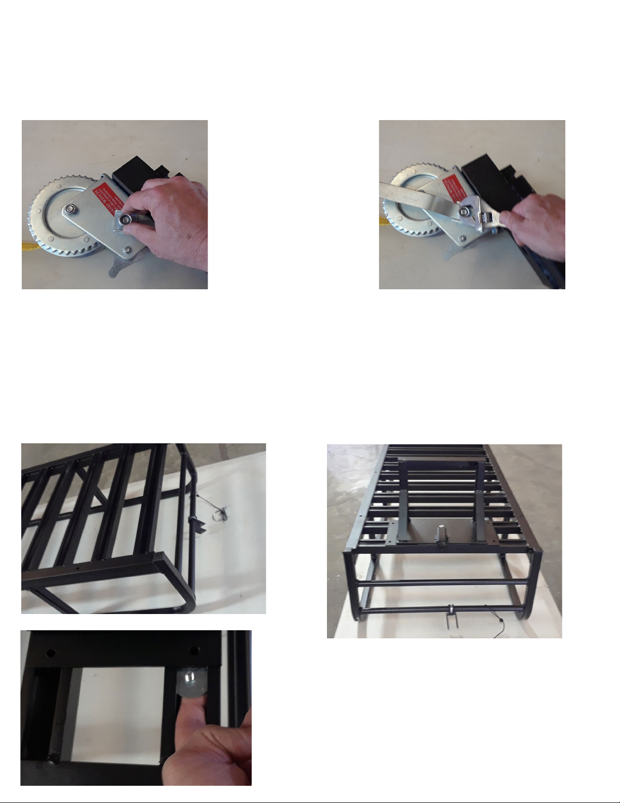
STEP 3: Place basket assembly upside down on work surface with handle
holder and locking pin facing to your right. (FIG.3) Place steering axle
assembly on right side of basket assembly and secure with 4- ¼”x ½”
bolts, 4- ¼”fender washers, and 4- ¼” jam locknuts.
(FIG. 4) NOTE: Place fender washer
on bolt and slip into opening of rung
on basket. (FIG. 5)
IG. 3
F
FIG. 5
FIG.4
PAGE 3 OF 9
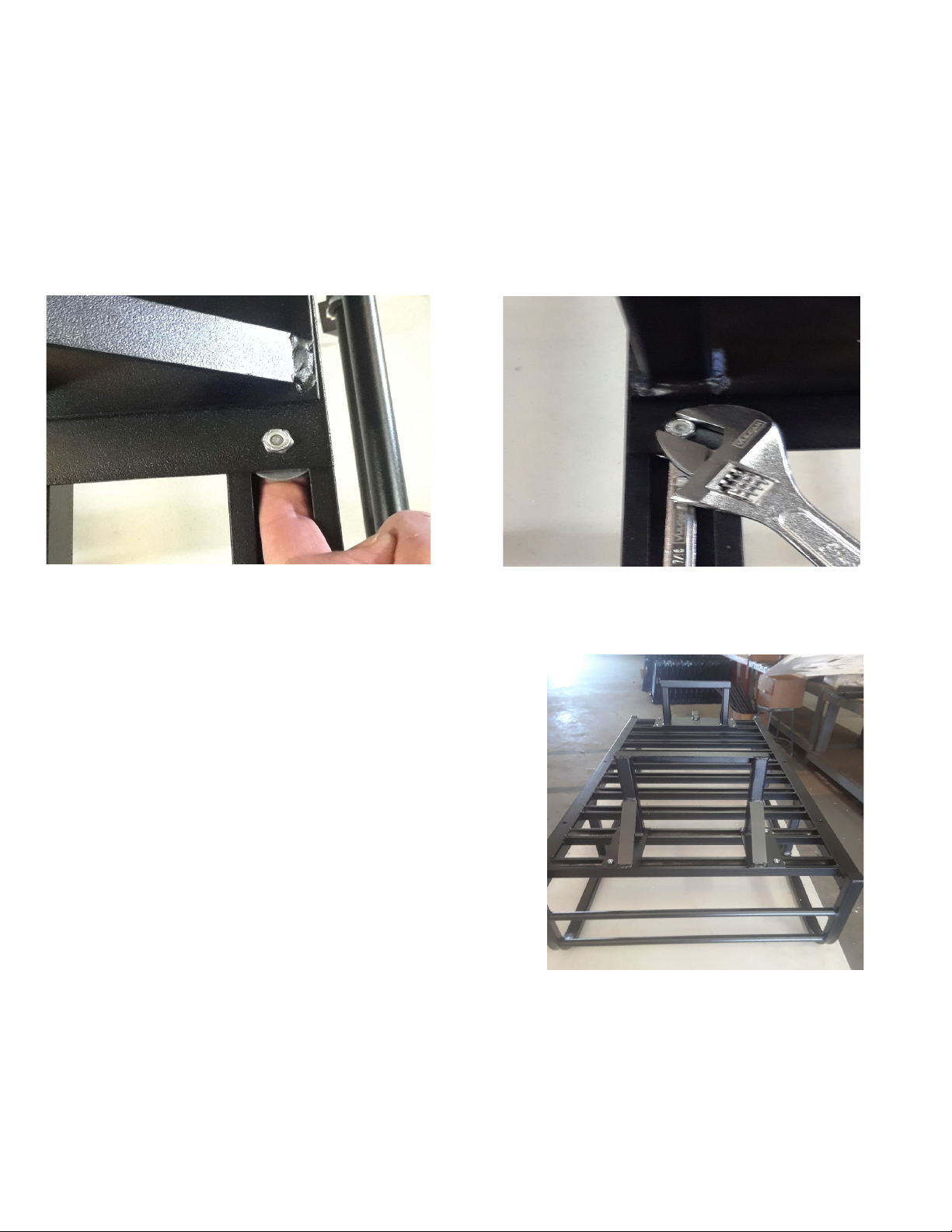
STEP 3 CONT’D: Slide bolt and washer under axle assembly and insert
through hole. Install locknut on bolt. HAND TIGHTEN ONLY! (FIG.6)
Repeat p
rocess with other 3 bolts. Center axle assembly in middle of
basket and tighten all 4 bolts securely. (FIG.7) NOTE: Washers will bow
as bolts are tightened.
FIG.6
FIG. 7
STEP 4: Follow instructions
for Step 3 to install rear axle
assembly to left
end of
FIG.8
basket. (FIG. 8)
STEP 5: Attach “L” basket bar to basket by placing “L” bar on basket
with
vertical part of bar towards you and turned down. (FIG. 9). Feed
5/16” x 5” bolt up through hole in center of basket and through the “L”
bar. Once end of bolt is visible, place center hole of support brace over
bolt and secure with flat washer and 5/16” locknut. Finger tighten only.
(FIG. 10).
 Loading...