

Page 1
Great Dane
®
GSRKA1934S
201018 10/02/2007
Page 2

Page 3

Introduction
Using Your Operator’s Manual
This manual is an important part of your machine and
should remain with the machine when you sell it.
Use the safety and operating information in the machine
operator’s manual to operate and service the machine
safely and correctly.
WARNING: The Engine Exhaust from this
product contains chemicals known to the
State of California to cause cancer, birth defects or other reproductive harm.
California Proposition 65 Warning
All information, illustrations and specifications
in this manual are based on the latest information at the time of publication. The right is
reserved to make changes at any time without
notice.
COPYRIGHT© 2007
Auburn Consolidated Industries, Inc.
All rights reserved
Great Dane, Chariot, Brutus, Scamper, Surfer,
and Super Surfer are registered trademarks
of Auburn Consolidated Industries, Inc.
An engine manufacturer’s owner’s manual has been pro
vided with your machine. This will provide maintenance and
troubleshooting information for the engine installed in your
machine.
Specifications and design are subject to change without
notice.
Special Messages
Your manual contains special messages to bring attention
to potential safety concerns, machine damage as well as
helpful operating and servicing information. Please read all
the information carefully to avoid injury and machine damage.
CAUTION: Avoid injury! This symbol and text
highlight potential hazards or death to the
operator or bystanders that may occur if the
hazards or procedures are ignored.
IMPORTANT: Avoid Damage! This text is used to tell
the operator of actions or conditions that might result
in damage to the machine.
NOTE: General information is given throughout the
manual that may help the operator in the operation or
service of the machine.
-
Product Identification
Record Identification Numbers
Surfer
GSRKA1934S Serial Number (637110001-)
If you need to contact an Authorized Service Center for
information on servicing, always provide the product model
and serial numbers.
You will need to locate the model and serial numbers for
the machine and for the engine of your machine and record
the information in the spaces provided.
Page 4
SAFETY LABELS
S/N
A
D
B
C
E
DATE OF PURCHASE:
_________________________________________
DEALER NAME:
_________________________________________
DEALER PHONE:
_________________________________________
Safety-Alert Symbol
The machine safety labels shown in this section are placed
in important areas on your machine to draw attention to
potential safety hazards.
On your machine safety labels, the words DANGER,
WARNING, and CAUTION are used with this safety-alert
symbol. DANGER identifies the most serious hazards.
The operator’s manual also explains any potential safety
hazards whenever necessary in special safety messages
that are identified with the word, CAUTION, and the safetyalert symbol.
Safety Labels
PRODUCT IDENTIFICATION NUMBER:
Model Number
_________________________________________
Serial Number
_________________________________________
ENGINE MODEL, SPECIFICATION, AND SERIAL
NUMBER:
Model Number
_________________________________________
Specification
_________________________________________
Serial Number
_________________________________________
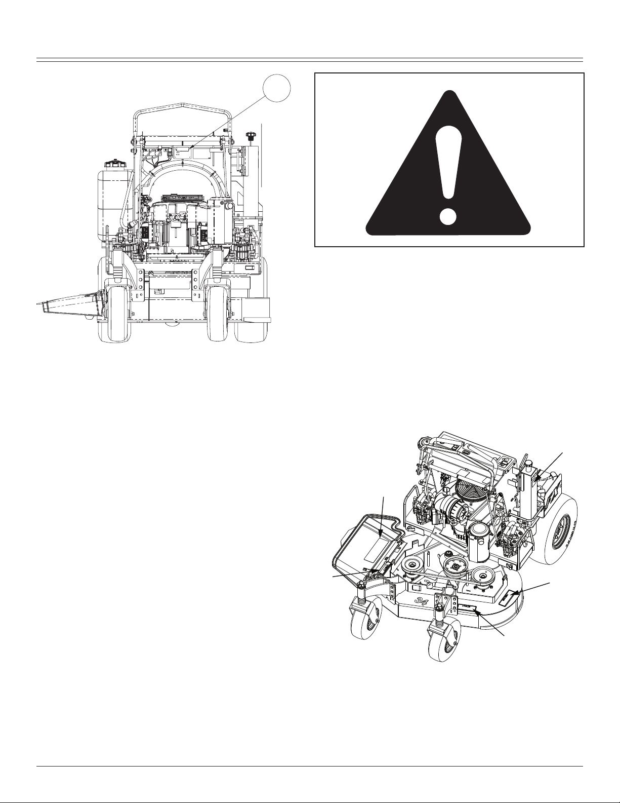
Safety Labels
Understanding The Machine Safety Labels
WARNING (A)
Hot Surface.
SAFETY LABELS - 2
Page 5
SAFETY LABELS
G
H
F
I
J
WARNING (B)
To avoid injury from rotating belts, keep all shields and
guards in place.
DANGER (C)
To avoid injury from rotating blades, stay clear of deck
edge.
DANGER (D)
To avoid injury from rotating blades and thrown objects,
stay clear of deck edge and keep others away. Do not mow
without discharge chute or entire grass catcher in place.
DANGER (E)
Do not mow without discharge chute or entire grass catcher
in place.
SAFETY LABELS - 3
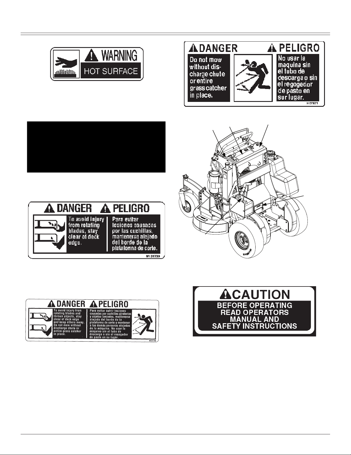
CAUTION: (F)
Before operating read operators manual and safety instructions.
CAUTION: HELP AVOID INJURY (G)
• Operator training required
• Read operator’s manual
• Keep shields in place
• Never carry riders
• Keep people a safe distance away
• Maintain all safety devices
• Before leaving machine:
• Stop engine
• Set park brake
• Remove key
Page 6

SAFETY
CAUTION (H)
Be safe! To avoid a fire hazard remove all leaves, grass
and debris from engine, hydro pumps and motors, pulleys,
belts, hoses, engine deck and cutter deck.
DANGER/POISON (I)
• Shield Eyes: Explosive gases can cause blindness or
injury.
• NO
• Sparks
• Flames
• Smoking
• Sulfuric acid can cause blindness or severe burns.
• Flush eyes immediately with water. Get medical help fast.
• Keep out of reach of children.
• Do not tip.
• Do not open battery.
WARNING (J)
To avoid injury from tipover, drive across slopes, not up and
down. If machine stops going uphill, stop blades and back
down slowly.
Emission Control System Certification Label
NOTE: Tampering with emission controls and components
by unauthorized personnel may result in severe fines or
penalties. Emission controls and components can only be
adjusted by EPA and/or CARB authorized service centers.
Contact your Great Dane Equipment Retailer concerning
emission controls and component questions.
The presence of an emissions label signifies that the en
-
gine has been certified with the United States Environmen
tal Protection Agency (EPA) and/or California Air Resources
Board (CARB).
The emissions warranty applies only to those engines marketed by Great Dane that have been certified by the EPA
and/or CARB; and used in the United States and Canada in
off-road mobile equipment.
Emission Compliance Period
If your engine has the emission compliance category listed
on the emission control system certification or air index
label, this indicates the number of operating hours for which
the engine has been certified to meet EPA and/or CARB
emission requirements. The following table provides the
engine compliance period in hours associated with the
category found on the certification label.
Agency Category Hours
EPA
EPA
EPA
CARB Moderate 125
CARB Intermediate 250
CARB Extended 500
Certification
Your product has been tested and evaluated by the manufacturer and conforms with American National Standard
B-71.4, “Safety Specifications” for commercial turf care
equipment.
C 250
B 500
A 1000
-
Safety
Operator Training Required
Read the operator’s manual and other training mate-
•
rial. If the operator or mechanic cannot read English, it
is the owner’s responsibility to explain this material to
them. This publication is available in other languages.
Become familiar with the safe operation of the equip-
•
ment, operator controls, and safety signs.
All operators and mechanics should be trained. The
•
owner of the machine is responsible for training the
users.
Never let children or untrained people operate or ser-
•
vice the equipment. Local regulations may restrict the
age of the operator.
The owner/user can prevent and is responsible for
•
accidents or injuries occurring to themselves, other
people, or property.
Operate the machine in an open, unobstructed area
•
under the direction of an experienced operator.
Preparation
Evaluate the terrain to determine what accessories and
•
attachments are needed to properly and safely perform
SAFETY - 4
Page 7

SAFETY
the job. Only use accessories and attachments approved by the manufacturer.
Wear appropriate clothing including hard hat, safety
•
glasses and hearing protection. Long hair, loose clothing or jewelry may get tangled in moving parts.
Inspect the area where the equipment is to be used
•
and remove all objects such as rocks, toys and wire
which can be thrown by the machine.
Use extra care when handling gasoline and other fuels.
•
They are flammable and vapors are explosive.
a. Use only an approved container.
b. Never remove gas cap or add fuel when engine
is running. Do not smoke.
c. Never refuel or drain the machine indoors.
Check that the operator’s presence controls, safety
•
switches and shields are attached and functioning
properly. Do not operate unless they are functioning
properly.
Operating Safely
Never run an engine in an enclosed area where dan-
•
gerous carbon monoxide fumes can collect.
Only operate in good light, keeping away from holes
•
and hidden hazards.
Be sure all drives are in neutral and parking brake is
•
engaged before starting engine. Only start engine from
the operator’s position. Use seat belts if provided.
Slow down and use extra care on hillsides. Be sure to
•
travel in the recommended direction on hillsides. For
this machine, drive across hillsides, not up and down.
Turf conditions can affect the machine’s stability. Use
caution while operating near drop-offs.
Slow down and use caution when making turns and
•
when changing directions on slopes.
Never raise deck with the blades running.
•
Never operate with the PTO shield, or other guards, not
•
securely in place. Be sure all interlocks are attached,
adjusted properly, and functioning properly.
Never operate with the discharge deflector raised,
•
removed or altered, unless using a grasscatcher. Do
not operate mower without discharge chute or entire
grasscatcher in place.
Do not change the engine governor setting or
•
overspeed the engine. Operating the engine at excessive speed can increase the hazard of personal injury.
Stop on level ground, lower implements, disengage
•
drives, engage parking brake, and shut off engine
before leaving the operator’s position for any reason
including emptying the grasscatchers or unclogging the
chute.
Stop equipment and inspect blades after striking ob-
•
jects or if an abnormal vibration occurs. Make necessary repairs before resuming operations.
Keep hands and feet away from the cutting units.
•
Look behind and down before backing up to be sure of
•
a clear path.
Never carry passengers and keep pets and bystanders
•
away.
Slow down and use caution when making turns and
•
crossing roads and sidewalks. Stop blades if not mowing. Watch for traffic when operating near or crossing
roadways.
Be aware of the mower discharge direction and do not
•
point it at anyone.
Do not operate the machine while under the influence
•
of alcohol or drugs.
Use care when loading or unloading the machine into
•
or off of a trailer or truck.
Use care when approaching blind corners, shrubs,
•
trees, or other objects that may obscure vision.
Inspect machine before you operate. Be sure hardware
•
is tight. Repair or replace damaged, badly worn, or
missing parts. Be sure guards and shields are in good
condition and fastened in place. Make any necessary
adjustments before you operate.
Before using, always visually inspect to see that the
•
blades, blade bolts and the mower assembly are not
worn and damaged. Replace worn and damaged
blades and bolts in sets to preserve balance.
Keep safety labels visible when installing accessories
•
and attachments.
Do not wear radio or music headphones. Safe service
•
and operation require your full attention.
When machine is left unattended, stored, or parked,
•
lower the mower deck unless a positive mechanical
lock is used.
Using a Spark Arrestor
The engine in this machine is not equipped with a spark arrestor muffler. It is a violation of California Public Resource
Code Section 4442 to use or operate this engine on or near
any forest-covered, brush-covered or grass-covered land
unless the exhaust system is equipped with a spark arrestor meeting any applicable local or state laws. Other states
or federal areas may have similar laws.
A spark arrestor for your machine may be available from
your authorized dealer. An installed spark arrestor must be
maintained in good working order by the operator.
Checking Mowing Area
Evaluate the terrain to determine what accessories and
•
attachments are needed to properly and safely perform
the job.
Clear mowing area of objects that might be thrown.
•
Keep people and pets out of mowing area.
Study mowing area. Set up a safe mowing pattern. Do
•
not mow where traction or stability is doubtful.
Test drive area with mower lowered but not running.
•
Slow down when you travel over rough ground.
SAFETY - 5
Page 8

SAFETY
Parking Safely
Stop machine on a level surface, not on a slope.
1.
Disengage mower blades.
2.
Lock the park brake.
3.
Stop the engine.
4.
Remove the key.
5.
Wait for engine and all moving parts to stop before you
6.
leave the operator’s station.
Close fuel shut-off valve, if your machine is equipped.
7.
Disconnect the negative battery cable or remove the
8.
spark plug wire (for gasoline engines) before servicing
the machine.
ROTATING BLADES ARE DANGEROUS!
HELP PREVENT SERIOUS OR FATAL ACCIDENTS:
Rotating blades can cut off arms and legs, and throw
•
objects. Failure to observe safety instructions could
result in serious injury or death.
Keep hands, feet and clothing away from mower deck
•
when engine is running.
Be alert at all times, drive forward carefully. People,
•
especially children can move quickly into the mowing
area before you know it.
Do not mow in reverse.
•
Shut off blades when you are not mowing.
•
Park machine safely before leaving the operator sta-
•
tion for any reason including emptying the catchers or
unplugging the chute.
PROTECT CHILDREN!
Death or serious injury can occur when young children
•
associate having fun with a lawn mowing machine
simply because someone has given them a ride on a
machine.
Children are attracted to lawn mowing machines and
•
mowing activities. They don’t understand the dangers
of rotating blades or the fact that the operator is unaware of their presence.
Children who have been given rides in the past may
•
suddenly appear in the mowing area for another ride
and be run over or backed over by the machine.
Tragic accidents with children can occur if the operator
•
is not alert to the presence of children, especially when
a child approaches a machine from behind. Before and
while backing up, stop mower blades and look down
and behind the machine carefully, especially for children.
Never carry children on a machine or attachment,
•
even with the blades off. Do not tow children in a cart
or trailer. They can fall off and be seriously injured or
interfere with safe machine operation.
Never use the machine as a recreational vehicle or to
•
entertain children.
Never allow children or an untrained person operate
•
the machine. Instruct all operators not to give children a
ride on the machine or in an attachment.
Keep children indoors, out of the mowing area, and in
•
the watchful eye of a responsible adult, other than the
operator, when a mower is being operated.
Stay alert to the presence of children. Never assume
•
that children will remain where you last saw them. Turn
the machine off if a child enters the work area.
Avoid Tipping
•
•
•
SAFETY - 6
Slopes are a major factor related to loss-of-control and
tip-over accidents, which can result in severe injury or
death. Operation on all slopes requires extra caution.
Mow across slopes, not up and down.
Watch for holes, ruts, bumps, rocks, or other hidden
objects. Uneven terrain could overturn the machine.
Tall grass can hide obstacles.
Page 9

Choose a low ground speed so you will not have to
•
stop or shift while on a slope.
Do not mow or operate machine on wet grass. Tires
•
may lose traction. • • • Tires may lose traction on slopes
even though the brakes are functioning properly.
Avoid starting, stopping or turning on a slope. If the
•
tires lose traction, disengage the blades and proceed
slowly, straight down the slope.
Keep all movement on slopes slow and gradual. Do
•
not make sudden changes in speed or direction, which
could cause the machine to roll over.
Use extra care while operating machine with grass-
•
catchers or other attachments, they can affect stability
of the machine. Do not use on steep slopes.
Do not mow near drop-offs, ditches, embankments, or
•
bodies of water. The machine could suddenly roll over if
a wheel goes over the edge or the edge caves in.
Follow the manufacturer’s recommendations for wheel
•
weights or counterweights for added stability when
operating on slopes or using front or rear mounted attachments. Remove weights when not required.
Drive machine very slowly and avoid quick stops when
•
attachment is removed.
Transport machine with decks lowered to improve
•
stability.
Keep Riders Off
Only allow the operator on the machine. Keep riders
•
off.
Riders on the machine or attachment may be struck by
•
foreign objects or thrown off the machine causing serious injury.
Riders obstruct the operator’s view resulting in the ma-
•
chine being operated in an unsafe manner.
Avoid High Pressure Fluids
Hydraulic hoses and lines can fail due to physical dam-
•
age, kinks, age, and exposure. Check hoses and lines
regularly. Replace damaged hoses and lines.
Hydraulic fluid connections can loosen due to physical
•
damage and vibration. Check connections regularly.
Tighten loose connections.
Escaping fluid under pressure can penetrate the skin
•
causing serious injury. Avoid the hazard by relieving
pressure before disconnecting hydraulic or other lines.
Tighten all connections before applying pressure.
Search for leaks with a piece of cardboard. Protect
•
hands and body from high pressure fluids.
If an accident occurs, see a doctor immediately. Any
•
fluid injected into the skin must be surgically removed
within a few hours or gangrene may result. Doctors
unfamiliar with this type of injury should reference a
knowledgeable medical source.
Checking Wheel Hardware
A serious accident could occur causing serious injury if
•
wheel hardware is not tight.
Check wheel hardware tightness often during the first
•
SAFETY
•
Wear Appropriate Clothing
•
•
•
•
Maintenance and Storage
•
•
•
•
•
•
•
•
•
•
•
•
•
•
•
SAFETY - 7
100 hours of operation.
Wheel hardware must be tightened to specified torque
using the proper procedure anytime it is loosened.
Always wear safety goggles, or safety glasses with side
shields, and a hard hat when operating the machine.
Wear close fitting clothing and safety equipment appropriate for the job.
While mowing, always wear substantial footwear and
long trousers. Do not operate the equipment when
barefoot or wearing open sandals.
Wear a suitable protective device such as earplugs.
Loud noise can cause impairment or loss of hearing.
Never operate machine in a closed area where dangerous carbon monoxide fumes can collect.
Disengage drives, lower implement, lock parking brake,
stop engine and remove key or disconnect spark plug
(for gas engines). Wait for all movement to stop before
adjusting, cleaning or repairing.
Clean grass and debris from cutting units, drives, mufflers, and engine to help prevent fires. Clean up oil or
fuel spillage.
Let engine cool before storing and do not store near
flame.
Shut off fuel while storing or transporting. Do not store
fuel near flames or drain indoors.
Park machine on level ground. Never allow untrained
personnel to service machine. Understand service
procedure before doing work.
Use jack stands or lock service latches to support components when required. Securely support any machine
elements that must be raised for service work.
Before servicing machine or attachment, carefully
release pressure from any components with stored
energy, such as hydraulic components or springs.
Release hydraulic pressure by lowering attachment or
cutting units to the ground or to a mechanical stop and
move hydraulic control levers back and forth.
Disconnect battery or remove spark plug (for gas
engines) before making any repairs. Disconnect the
negative terminal first and the positive last. Reconnect
positive first and negative last.
Use care when checking blades. Wrap the blades or
wear gloves, and use caution when servicing them.
Only replace blades. Never straighten or weld them.
Keep hands, feet, clothing, jewelry and long hair away
from moving parts. If possible, do not make adjustments with the engine running.
Charge batteries in an open well ventilated area, away
from spark and flames. Unplug charger before connecting or disconnecting from battery. • Wear protective
clothing and use insulated tools.
Keep all parts in good working condition and all hardware tightened. Replace all worn or damaged decals.
Check grass catcher components and the discharge
guard frequently and replace with manufacturer’s rec-
Page 10

SAFETY
ommended parts, when necessary. Grass catcher components are subject to wear, damage, and deterioration
which could expose moving parts or allow objects to be
thrown.
Keep all nuts and bolts tight, especially blade attach-
•
ment bolts, to be sure the equipment is in safe working
condition.
Check brake operation frequently. Adjust and service
•
as required.
On multi-bladed machines, take care as rotating one
•
blade can cause other blades to rotate.
Prevent Fires
Remove grass and debris from engine compartment
•
and muffler area, before and after operating machine,
especially after mowing or mulching in dry conditions.
Empty the grass catcher completely before storing.
•
Always shut off fuel when storing or transporting ma-
•
chine, if the machine has a fuel shutoff.
Do not store machine near an open flame or source of
•
ignition, such as a water heater or furnace.
Check fuel lines, tank, cap, and fittings frequently for
•
cracks or leaks. Replace if necessary.
clothing, change clothing immediately. If fuel is spilled
near machine, do not attempt to start the engine but
move the machine away from the area of spillage.
Avoid creating any source of ignition until fuel vapors
have dissipated.
Never store the machine or fuel container where there
•
is an open flame, spark, or pilot light such as on a water heater or other appliance.
Prevent fire and explosion caused by static electric dis-
•
charge. Static electric discharge can ignite fuel vapors
in an ungrounded fuel container.
Never fill containers inside a vehicle or on a truck or
•
trailer bed with a plastic liner. Always place containers
on the ground away from your vehicle before fueling.
Tire Safety
Explosive separation of a tire and rim parts can cause serious injury or death:
Do not attempt to mount a tire without the proper equip-
•
ment and experience to perform the job.
Always maintain the correct tire pressure. Do not inflate
•
the tires above the recommended pressure. Never weld
or heat a wheel and tire assembly. The heat can cause
an increase in air pressure resulting in a tire explosion.
Welding can structurally weaken or deform the wheel.
When inflating tires, use a clip-on chuck and extension
•
hose long enough to allow you to stand to one side and
NOT in front of or over the tire assembly.
Check tires for low pressure, cuts, bubbles, damaged
•
rims or missing lug bolts and nuts.
Handling Fuel Safely
To avoid personal injury or property damage, use
extreme care in handling fuel. Fuel is extremely flammable and fuel vapors are explosive:
Extinguish all cigarettes, cigars, pipes, and other
•
sources of ignition.
Use only an approved fuel container. Use only non-
•
metal, portable fuel containers approved by the Underwriter’s Laboratory (U.L.) or the American Society for
Testing & Materials (ASTM). If using a funnel, make
sure it is plastic and has no screen or filter.
Never remove the fuel tank cap or add fuel with the
•
engine running. Allow engine to cool before refueling.
Never add fuel to or drain fuel from the machine in-
•
doors. Move machine outdoors and provide adequate
ventilation.
Clean up spilled fuel immediately. If fuel is spilled on
•
Remove fuel-powered equipment from the truck or
•
trailer and refuel it on the ground. If this is not possible,
then refuel such equipment with a portable container,
rather than from a fuel dispenser nozzle.
Keep the nozzle in contact with the rim of the fuel tank
•
or container opening at all times until the fueling is
complete. Do not use a nozzle lock-open device.
Never overfill fuel tank. Replace fuel tank cap and
•
tighten securely.
Replace all fuel container caps securely after use.
•
For gasoline engines, do not use gas with methanol.
•
Methanol is harmful to your health and to the environment.
Handling Waste Product and Chemicals
Waste products, such as, used oil, fuel, coolant, brake
•
fluid, and batteries, can harm the environment and
people:
Do not use beverage containers for waste fluids -
•
someone may drink from them.
See your local Recycling Center or authorized dealer to
•
learn how to recycle or get rid of waste products.
A Material Safety Data Sheet (MSDS) provides spe-
•
cific details on chemical products: physical and health
hazards, safety procedures, and emergency response
techniques. The seller of the chemical products used
with your machine is responsible for providing the
MSDS for that product.
SAFETY - 8
Page 11
OPERATING
B
H
F
I
A
E
C
D
G
H
I
J
K
L
A
Operating
Daily Operating Checklist
Make sure all necessary guards and shields are safely
and securely attached. Check for loose, missing, or
damaged parts.
Remove mower deck belt shields. Clean grass and
debris from belt area.
Remove grass and debris from machine and mower
deck.
Remove grass and debris from operator station foot
plate, pump drive belt compartment, hydraulic pump
and pump mounting plate.
Test park brake.
Test safety systems.
Check battery.
Check for oil leaks.
Check engine oil and hydraulic oil levels.
Check all belts for damage or cracking.
Check engine air filter.
Check mower level.
Adjust cutting height if necessary.
Check wheel bolt torque. Tighten if necessary.
Check tire air pressure. Check tires for damage or
cracking.
Check and adjust speed control linkages and lock.
Avoid Damage to Plastic and Painted Surfaces
Do not wipe plastic parts unless rinsed first.
•
Insect repellent spray may damage plastic and painted
•
surfaces. Do not spray insect repellent near machine.
Be careful not to spill fuel on machine. Fuel may dam-
•
age surface. Wipe up spilled fuel immediately.
Prolonged exposure to sunlight will damage the hood
•
surface.
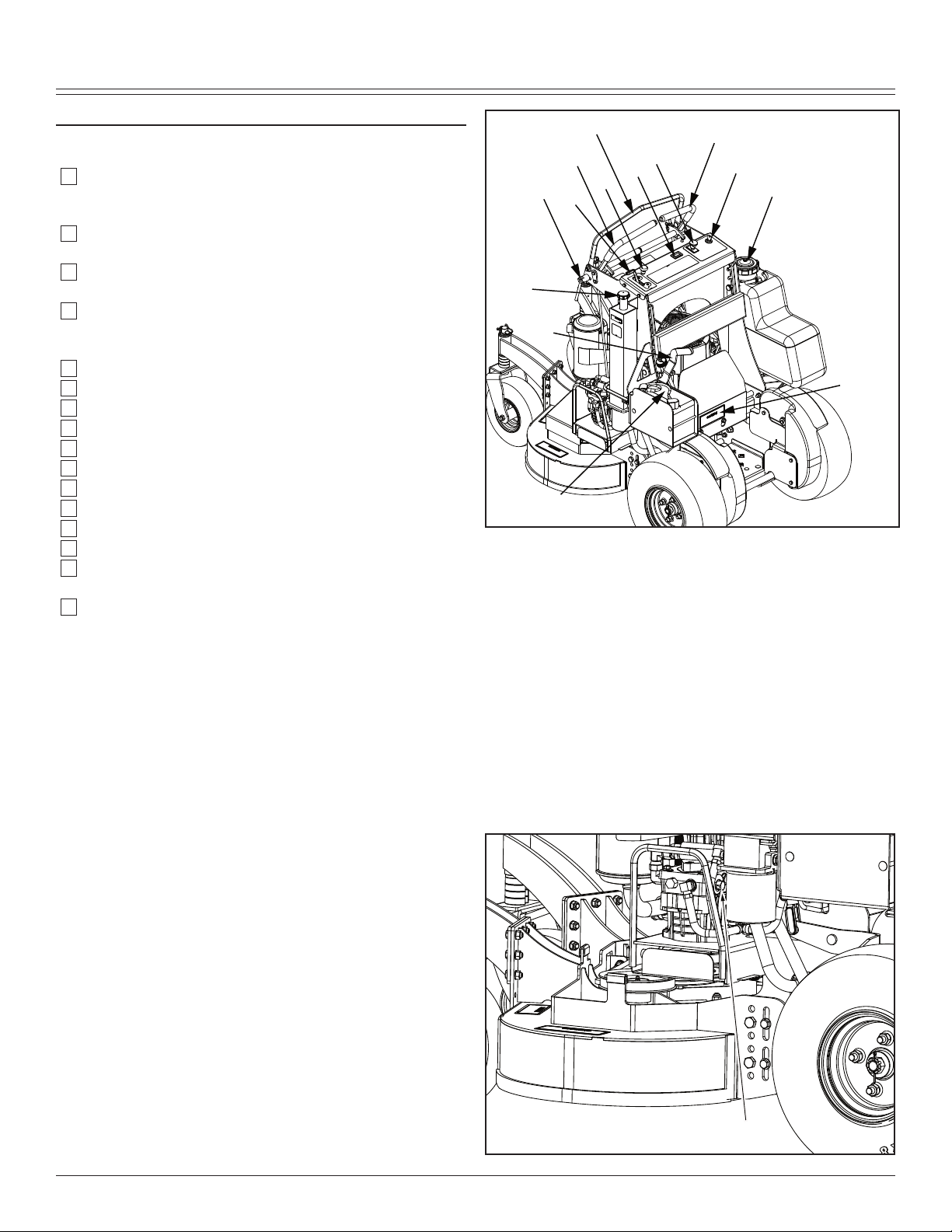
Operator Station Controls
A-Speed Control Bar Lock
B-Speed Control Bar
C-Right Motion Control Lever
D-Left Motion Control Lever
E-Hydrostatic Oil Reservoir Cap and Dipstick
F-Ignition Key Switch
G-Fuel Tank Cap
H-PTO Switch
I-Hour Meter
J-Choke
K-Throttle Lever
L-Park Brake Lever
Miscellaneous Controls
OPERATING - 9
Page 12
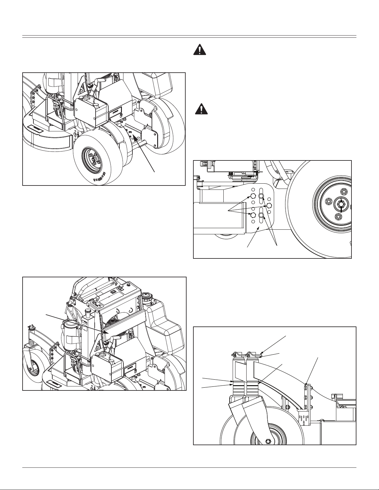
A-Free-Wheeling Valves
A
A
A
B
C
D
E
F
G
H
Caster Mounting
In Upper Position
Mounting and Dismounting Machine Safely
Step on operator’s platform (A) at the rear of machine
1.
to mount the machine.
Park machine safely. (See Parking Safely in the
2.
SAFETY section.)
Step off operator’s platform to dismount machine.
3.
Keep operator’s platform and suspension springs clean
4.
and free of debris.
OPERATING
CAUTION: Avoid injury! Before adjusting cut-
Check tire pressure. Inflate front caster wheels to 172-
1.
207 CPA (25-30 psi). Inflate rear tires to 69-83 CPA
(10-12 psi).
CAUTION: Avoid injury! Machine must be
Using a suitable lifting device, lift the rear of the ma-
2.
chine.
ting height, stop engine and lock the park
brake.
safely supported on jack stands before removing or installing wheels. Do not use a hoist or
floor jack to support the machine.
Raising and Lowering Thigh Pad
Park machine safely. (See Parking Safely in the
1.
SAFETY section.)
Adjust the pad (A) as required by lifting or lowering the
2.
pad to where it is comfortable.
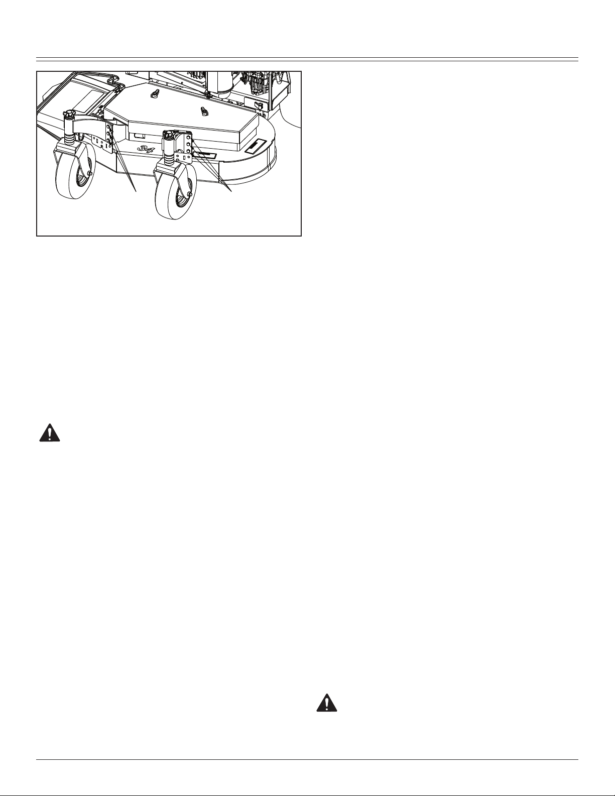
Adjusting Cutting Height
Cutting height can be adjusted from approximately 38-114
MM. (1-1/2 - 4-1/2 in.). Each hole adjusts the height of cut
(HOC) in 12 MM. (1/2 in.) increments.
Loosen bolts (A).
3.
Loosen and remove bolts (B).
4.
Move deck (C) up or down to desired height and tighten
5.
bolts (A) to 47-54 N•m (35-40 lb-ft).
Insert bolts (B) into holes and tighten to 95-108 N•m
6.
(70-80 lb-ft).
Remove lynch pin (D) and spacer bushing (E).
7.
OPERATING - 10
Page 13

OPERATING
IMPORTANT: Do not allow washer (G) to set on
caster yoke. It must be on top of height-of-cut
spacer bushings (H).
NOTE: Adjust caster wheel spacers to keep
mower deck tilted slightly down at the front.
Adjust caster wheel spacers (F) to compensate front
8.
HOC accordingly.
Setting Cutting Height
NOTE: Before setting cut height, ensure the
tires are all set at the correct tire pressures.
Caster to deck mounting position
Caster to deck mounting - Upper Positon
Rear of Deck Front Casters
Rear Deck Nominal Height C-Spacers C-Spacers Height of Cut Deck Rake
Hole Position Top Bottom (inches) (inches)
1 4.5 NA
1 4.5
1 4.5
2 3.5 0 4 3.5 0
2 3.5 1 3 3 0.5
2 3.5 2 2 2.5 1
3 2.5 2 2 2.5 0
3 2.5 3 1 2 0.5
3 2.5 4 0 1.5 1
Caster to deck mounting - Lower Positon
Rear of Deck Front Casters
Rear Deck Nominal Height C-Spacers C-Spacers Height of Cut Deck Rake
Hole Position Top Bottom (inches) (inches)
1 4.5 1 3 4.5 0
1 4.5 2 2 4 0.5
1 4.5 3 1 3.5 1
2 3.5 3 1 3.5 0
2 3.5 4 0 3 0.5
2 3.5 NA
3 2.5
3 2.5
3 2.5
OPERATING - 11
Page 14
OPERATING
do not operate machine. See your authorized dealer for
service.
Perform these tests in a clear open area. Keep bystanders
away.
Testing PTO Switch
Stand on operator’s platform with motion control levers
1.
in the neutral position.
Lock park brake.
2.
Pull PTO switch up to engage.
3.
Turn key switch to the start position.
4.
Result: The engine must not crank.
HOLE LOCATIONS
To adjust the rear height of cut, use the chart above and
match the hole locations on the chart up to the hole locations on the picture.
To adjust the front height of cut, use the chart above and in
sert the number of C-spacers to correspond to the number
on the chart to achieve the height of cut you desire.
NOTE: Rake is described as the amount that the rear
of the deck is above the front of the deck. Your best
cut will occur when you have at least some rake on the
deck.
Testing Safety Systems
CAUTION: Avoid injury! Engine exhaust fumes
contain carbon monoxide and can cause serious illness or death.
Move the machine to an outside area before running the
engine.
Do not run an engine in an enclosed area without adequate
ventilation.
• Connect a pipe extension to the engine exhaust pipe to
direct the exhaust fumes out of the area.
• Allow fresh outside air into the work area to clear the
exhaust fumes out.
The safety systems installed on your machine should be
checked before each machine use. Be sure you have read
the machine operator manual and are completely familiar
with the operation of the machine before performing these
safety system checks.
Testing Park Brake Switch
Push PTO switch down to disengage.
1.
Unlock park brake.
2.
Turn key switch to the start position.
3.
Result: The engine must not crank.
-
Testing Neutral Switch (Start)
Lock park brake.
1.
Push PTO switch down to disengage.
2.
Push one motion control lever forward.
3.
Turn key switch to the start position.
4.
Result: The engine must not crank.
Testing Neutral Switch (Run)
Lock park brake.
1.
Push PTO switch down to disengage.
2.
Start engine.
3.
Push one motion control lever forward.
4.
Repeat procedure using the other lever.
5.
Repeat procedure pushing each motion control lever
6.
rearward.
Result: The engine must stop when either lever is moved
from neutral position.
Testing Operator Presence Switch
NOTE: Ensure OPC switch bracket is depressed when
standing on operator’s station.
Stand on operator’s platform with motion control levers
1.
in the NEUTRAL position.
Start engine.
2.
Unlock park brake.
3.
Step completely off operator’s platform.
4.
Result: The engine must stop.
NOTE: Ensure OPC switch bracket is depressed when
standing on operator’s station.
Stand on operator’s platform with motion control levers
5.
in the NEUTRAL position and start engine.
Use the following checkout procedures to check for normal
operation of machine.
If there is a malfunction during one of these procedures,
OPERATING - 12
CAUTION: Avoid injury! Thrown objects can be
dangerous. Before operating the attachment:
Page 15
OPERATING
A
A
A
B
D
C
Clear area of bystanders, especially children.
Pick up objects which may be thrown by the attachment.
Pull PTO switch up to engage.
6.
Step completely off operator’s platform.
7.
Result: The engine must stop.
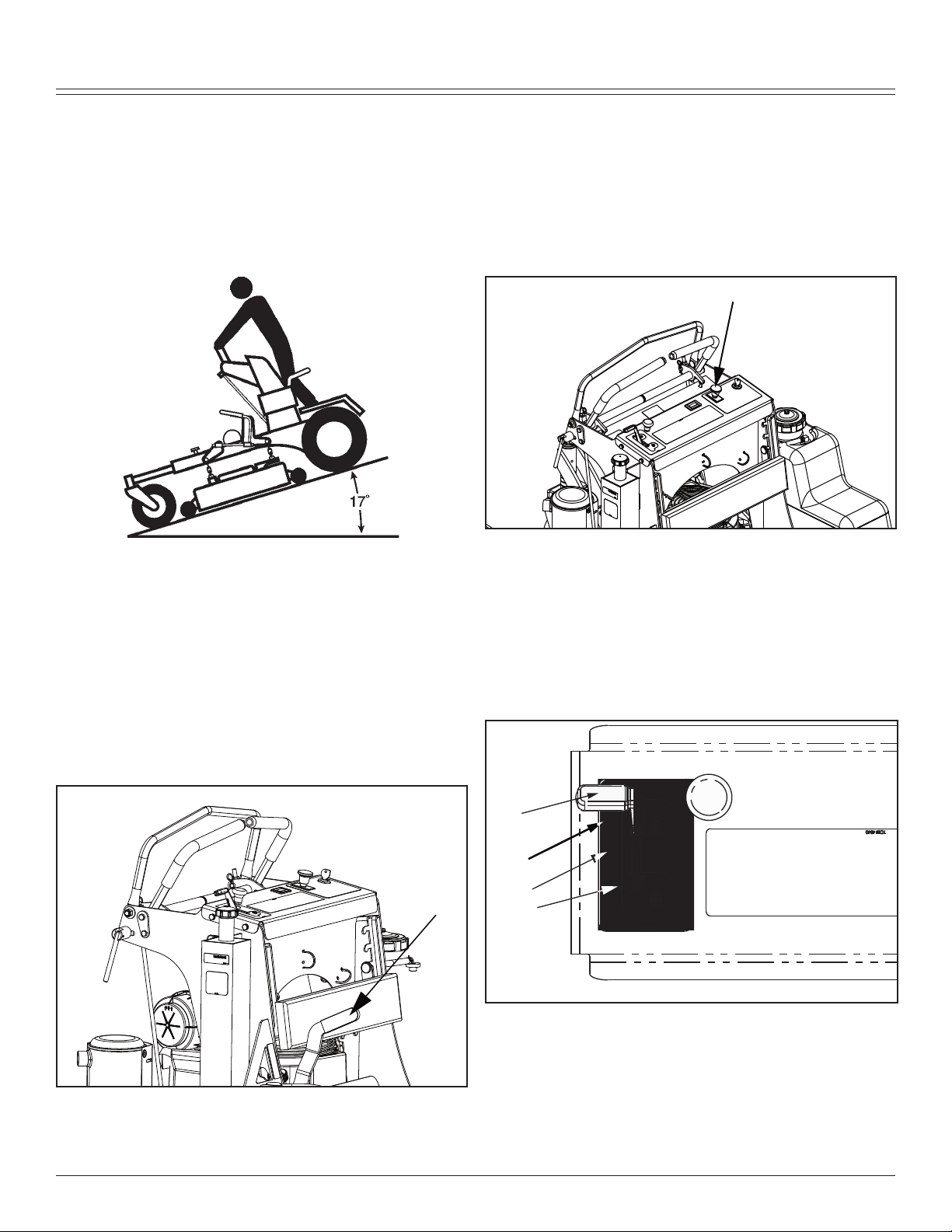
Testing the Park Brake
Stop machine on a 17° slope (30% grade) facing down-
1.
hill. Stop the engine and lock the park brake.
Repeat procedure with machine facing uphill.
2.
Result: Park brake must hold the machine stationary. (Machine should move no more that 61cm (24 in.) in one hour.)
If machine moves more than that, brakes need to be adjusted. See your authorized dealer or refer to Adjusting Park
Brake in the SERVICE STEERING AND BRAKES section.
Using the PTO
Engage PTO:
Stand on operator’s platform with motion control levers
1.
in the neutral position.
Start engine.
2.
Release park brake.
3.
Move throttle lever to the 1/2 to 3/4 fast position.
4.
Pull PTO knob (A) up to engage mower deck.
5.
Move throttle lever forward to the fast position for mow-
6.
ing.
Disengage PTO:
Push PTO knob (A) down.
1.
Set park brake.
2.
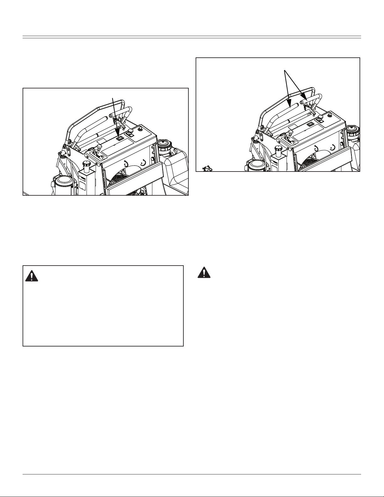
Using the Throttle
Using Park Brake
Locking Park Brake
Raise park brake lever (A) to lock park brake.
Unlocking Park Brake:
Lower park brake lever (A) to unlock park brake.
OPERATING - 13
Push throttle lever (A) forward to the fast position (B)
•
when mowing.
Move throttle lever (A) to the half fast position (C) when
•
starting and warming the engine.
Pull throttle lever (A) backward to the slow position (D)
•
to idle engine. Do not run engine at slow idle any longer than necessary for cooldown after mowing.
Page 16
OPERATING
A
A
Using the Hourmeter
NOTE: The machine is equipped with an electric start.
The hourmeter will continue to run with the key switch
in the run position.
Hourmeter (A) shows number of hours the machine
•
has been operated.
Use hourmeter and SERVICE INTERVAL section to
•
determine when machine needs service.
Using the Motion Control Levers
The functions of the motion control levers are:
Neutral Position
Picture Note: Motion control levers (A) shown in the neutral
position.
Machine speed, motion and direction can be controlled
•
when the engine is running and park brake is unlocked.
Operator can exit the mower with the engine running
•
when the park brake is locked and the PTO switch is
disengaged.
Forward and Reverse Motion:
CAUTION: Avoid injury! Learn use of the motion
control levers and practice at half throttle until
becoming proficient and comfortable with the
operation of the machine.
Do not move motion control levers from forward
to reverse or reverse to forward position rapidly.
Sudden direction changes could cause loss of
control or damage the machine.
• Steering.
• Acceleration.
• Deceleration.
CAUTION: Avoid injury! Children or bystanders
may be injured by runover and rotating blades.
Before traveling forward or rearward:
Carefully check the area around the machine.
•
Disengage the mower before backing up.
•
Move throttle lever to the fast position.
1.
Unlock park brake.
2.
Push motion control levers forward to begin forward
3.
motion. The further forward the control levers are
moved, the faster the machine will travel.
Forward speed range: 0–14 km/h (0–8.7 mph)
•
Pull both motion control levers rearward at the same
4.
time to begin reverse motion.
Reverse speed range: 0–6.4 km/h (0–4 mph)
•
To stop motion, move both motion control levers for-
5.
ward or rearward until the machine comes to a stop.
NOTE: The motion control linkages are adjust-
able. If adjustment is required, see Checking
and Adjusting Motion Control Linkages in the
SERVICE TRANSMISSION section.
OPERATING - 14
Page 17
OPERATING
Forward:
Push both motion control levers forward at the same
•
time.
Reverse:
• Push right motion control lever further forward than the
left motion control lever
Gentle Right Turn:
• Push left motion control lever further forward than the right
motion control lever.
Sharp Left Turn:
Pull both motion control levers past center rearward at
•
the same time.
Gentle Left Turn:
• Push right motion control lever forward and pull left motion
control lever rearward at the same time.
Sharp Right Turn:
OPERATING - 15
Page 18
OPERATING
D
B
C
A
E
A
B
C
D
• Push left motion control lever forward and pull right motion
control lever rearward at the same time.
Starting Engine
Put motion control levers (A) in the NEUTRAL position.
3.
Push PTO switch knob (B) down to disengage PTO.
4.
Move throttle lever (C) to set engine speed at the 1/2 to
5.
3/4 fast position.
Position choke knob (D):
6.
Cold engine: Pull knob up to the CHOKE position.
•
Warm/Hot engine: If necessary, pull knob up to the
•
CHOKE position.
Turn key switch (E) to the START position.
7.
Release key to the RUN position when engine starts.
8.
With engine started:
9.
• Push choke knob to the OFF position.
• Move throttle lever to the FAST position.
• Unlock park brake.
Engaging Mower
CAUTION: Avoid injury! Clear mowing area of
all bystanders when operating this machine.
Thrown objects could cause serious injury or
death.
CAUTION: Avoid injury! Engine exhaust fumes
contain carbon monoxide and can cause serious
illness or death.
Move the machine to an outside area before running
the engine.
Do not run an engine in an enclosed area without
adequate ventilation.
• Connect a pipe extension to the engine exhaust
pipe to direct the exhaust fumes out of the area.
• Allow fresh outside air into the work area to clear
the exhaust fumes out.
Stand on operator’s platform.
1.
Lock park brake.
2.
Keep hands and feet away from blades and discharge opening.
Do not mow in reverse unless absolutely necessary.
IMPORTANT: Avoid damage! To help prevent
damage to PTO clutch:
• Do not engage PTO with throttle in the fast
position.
Adjust mower deck to desired cutting height.
1.
Start engine.
2.
Move throttle lever (A) to the 1/2 to 3/4 fast position.
3.
Unlock park brake.
4.
OPERATING - 16
Page 19
OPERATING
C
A
B
NOTE: In cold weather or with a new machine, allow
engine to reach operating temperature before engaging
PTO to prevent engine from stalling.
Pull PTO knob (B) up to engage mower deck.
5.
Move throttle lever to the fast position (C).
6.
NOTE: The travel speed and turn rate will vary with the
amount that the motion control levers are moved.
Push motion control levers (D) forward slowly. Mow at a
7.
safe travel speed.
Stopping the Engine
IMPORTANT: Avoid damage! To help prevent engine backfiring, throttle lever should be set at the half-speed position
prior to stopping the engine.
Do not stop engine when mower is on a slope of more than
30 degrees for an extended period of time. Oil may run
through valve train into carburetor and muffler.
Lock park brake.
1.
Reduce engine speed to half-throttle.
2.
Turn key switch to STOP position (C).
3.
Remove key.
4.
Using Pump Free-Wheel Valves
Turn both pump free-wheel valves (C) counterclock-
2.
wise approximately one full turn (open position).
Unlock park brake.
3.
Push machine to desired location. Due to hydraulic
4.
system drag, machine will move slowly.
Turn pump free-wheel valves (C) on both pumps one
5.
full turn clockwise (closed position). Tighten valves to
11 N•m (100 lb-in.).
Lock park brake.
6.
CAUTION: Avoid injury! With the free-wheeling
valve open, the machine will have unrestricted
motion.
• The machine may free-wheel out of control if
the free-wheeling valve is opened with the
machine on an incline.
• Park the machine on a level surface before
opening the free-wheeling valve.
IMPORTANT: Avoid Damage! Transmission damage may
occur if the machine is towed or moved incorrectly:
Move machine by hand only.
•
Do not use another vehicle to move machine.
•
Do not tow machine.
•
NOTE: The pump free-wheel valves must be turned
fully clockwise (closed) during normal machine operation.
When the machine needs to be moved without starting the
engine, use the pump free-wheel valves:
Lock park brake.
1.
Transporting Machine on a Trailer
Use a heavy-duty trailer to transport your machine. Trailer
must have signs and lights required by law.
CAUTION: Avoid injury! Use extra care when load-
ing or unloading the machine into a trailer or truck.
• Close fuel shut-off valve, if your machine is
equipped.
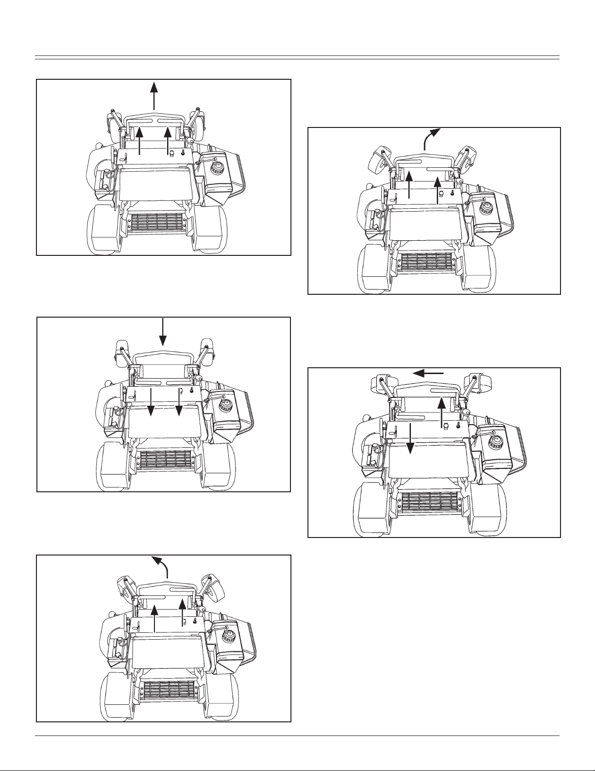
Raise mower deck to the transport position.
1.
Drive machine onto a trailer.
2.
Stop engine and lock park brake.
3.
Remove key.
4.
Fasten machine to trailer with heavy-duty straps,
5.
chains or cables. Both front and rear straps must be
directed downward and outward from machine.
Mowing Tips
• Mow grass with throttle lever in the full fast position.
• Cut grass when it is dry.
• Keep mower deck and discharge chute clean.
• Mow with sharp blades.
• Properly level mower deck for a smooth cut.
• Mow grass high and often.
OPERATING - 17
Page 20

SERVICE INTERVALS
• Use a travel speed that fits the conditions:
• Mow tall or wet grass twice. Cut grass at half desired
height – then cut at desired height.
• Travel slow when mowing tall, thick or wet grass.
• Avoid damaging grass by slipping or skidding machine
drive wheels. Practice smooth control lever movements.
• When performing sharp turns, do not allow inside machine drive wheel to stop and twist on grass.
Mowing Travel Speeds
Use slow travel speeds for:
• Slopes.
• Trimming.
• Close quarters.
• Tall grass.
Use faster travel speeds for:
Normal mowing on level ground.
•
CAUTION: Avoid injury! Help prevent serious
injury. Keep hands and feet away from blades
and the discharge opening.
• Do not step on either side of the mower deck when
mounting and dismounting the machine. Mount and
dismount the machine using the front foot plate.
Park machine on a hard, level surface.
1.
Disengage PTO.
2.
Move motion control levers to the neutral position.
3.
Lock park brake.
4.
Stop engine and remove key. Wait for mower blades to
5.
stop turning before leaving operator’s position.
Service Intervals
Servicing Your Machine
IMPORTANT: Avoid Damage! Operating in extreme condi-
tions may require more frequent service intervals:
• Engine components may become dirty or plugged
when operating in extreme heat, dust or other severe conditions.
• Engine oil may lose efficiency if vehicle is operated
constantly at slow or low engine speeds or with
frequent short trips.
Servicing Engine
See engine manufacturer’s owner’s manual provided with
your machine for engine service information.
Break-In (After First 10 Hours)
• Check air pressure in tires.
• Check wheel bolt torque.
• Check and adjust park brake.
• Change engine oil and filter.
• Check mower deck drive belt tension.
• Check hydraulic pump drive belt.
• Check transmission neutral adjustment.
Every 40 Hours
• Check air pressure in tires.
• Check wheel bolt torque.
• Check and adjust park brake.
• Change engine oil and filter.
• Check foam and paper air cleaner elements.
• Clean engine shrouds as needed.
• Lubricate front caster spindles and wheels.
• Lubricate mower deck idler pivot.
• Check mower deck drive belt tension.
• Lubricate hydraulic pump idler pivot.
• Check hydraulic pump drive belt.
• Check hydraulic fluid level.
• If operating machine in extremely dusty or dirty conditions:
• Clean behind engine shrouds and exposed fins.
• Remove screws on blower fan screen and clean
behind.
Every 100 Hours
• Lubricate mower deck spindles.
• Clean and gap spark plugs.
• Check hydraulic pump drive belt.
• Clean behind engine shrouds and exposed fins.
• Remove screws on blower fan screen and clean behind.
Every 500 Hours
• Change hydraulic oil and filter.
Yearly
• Change fuel filter.
• Clean battery.
• Change engine oil and filter at least once per season.
• Change hydraulic oil and filter at least once per season.
• Replace spark plugs.
Please use the following timetables to perform routine
maintenance on your machine.
SERVICE INTERVALS- 18
Page 21

SERVICE ENGINE
A
B
A
A
B
Service Lubrication
Grease
IMPORTANT: Avoid Damage! The recommended grease is
effective within an average air temperature range of -29 to
135 degrees C (-20 to 275 degrees F).
IMPORTANT: Avoid Damage! Use only NLGI No. 2 lithium
based grease.
• If operating outside that temperature range, contact your
servicing dealer for a special-use grease.
Use a general all-purpose grease with an NLGI grade No.2
rating.
Wet or high speed conditions may require use of a specialuse grease. Contact your Servicing dealer for information.
Lubricating Front Caster Spindles and Wheels
CAUTION: Avoid injury! Fingers or loose
clothing can get caught in rotating parts. Stop
engine and wait for all moving parts to stop
before servicing.
Lubricating Pump Idler Pivot
Lubricate one pump idler pivot grease fitting (A). Lubri-
•
cate either the fitting on the top of the engine bed or the
one under the pump shield.
Lubricating Mower Deck Spindles
• Lubricate two spindle grease fittings (A) and two wheel
grease fittings (B).
• Lubricate three mower deck spindle grease fittings (A).
Lubricating Mower Deck Idler Pivot
• Lubricate one deck idler pivot grease fitting (B).
SERVICE ENGINE- 19
Page 22

SERVICE ENGINE
�
Service Engine
Avoid Fumes
CAUTION: Avoid injury! Engine exhaust fumes
contain carbon monoxide and can cause serious illness or death.
Move the machine to an outside area before
running the engine.
Do not run an engine in an enclosed area without adequate ventilation.
• Connect a pipe extension to the engine ex
haust pipe to direct the exhaust fumes out
of the area.
• Allow fresh outside air into the work area to
clear the exhaust fumes out.
-
Engine Oil
Use oil viscosity based on the expected air temperature
range during the period between oil changes.
Use oil that meets the following specification:
• See the engine manufacturer’s owner’s manual provided
with your machine for the correct specifications.
Checking Engine Oil Level
IMPORTANT: Avoid Damage! Failure to check the oil
level regularly could lead to serious engine problems
if oil level is low:
Check oil level before operating.
•
Keep oil level between the FULL and the ADD
•
marks.
Check oil level when engine is stopped, level,
•
and is cooled so oil has had time to drain into the
sump.
Remove dipstick (A). Wipe with a clean cloth.
4.
NOTE: Allow dipstick cap to rest on threads of filler
tube when checking oil level. Do not tighten dipstick
cap when checking oil level.
Install dipstick and allow the cap to rest on the threads
5.
of the tube. Do not tighten the cap.
IMPORTANT: Avoid Damage! To prevent extensive
engine wear or damage, always maintain the proper
engine oil level. Never operate the engine with the oil
level below the add mark or over the full mark.
Remove dipstick and check oil level on dipstick. Oil
6.
must be between the ADD and FULL marks.
NOTE: Refer to engine manufacturers operating
manual for correct type and grade of oil.
If oil is low, add oil to bring oil level no higher than
•
the FULL mark on dipstick.
If oil level is above the FULL mark, drain to proper
•
level.
Install and tighten dipstick.
7.
NOTE: Check oil twice a day if you run engine over 4
hours in a day.
Make sure engine is cool when checking engine oil level.
1. Park machine safely. (See Parking Safely in the
SAFETY section.)
2. Allow engine to cool.
3. Clean area around dipstick to prevent debris from falling
into crankcase.
SERVICE ENGINE- 20
Changing Engine Oil and Filter
CAUTION: Avoid injury! Touching hot surfaces
can burn skin. The engine, components, and
fluids will be hot if the engine has been running. Be cautious and wear protective clothing
when servicing or working near a hot engine
and components.
Page 23

SERVICE ENGINE
IMPORTANT: Avoid Damage! Change the oil more often
if the machine is used in extreme conditions:
Extremely dusty conditions.
Frequent slow or low-speed operation.
Frequent short trips.
Clean area around dipstick cap and filter.
1.
Start engine and run until it reaches normal operating
2.
temperature.
Park machine safely. (See Parking Safely in the
3.
SAFETY section.)
two minutes. Check for leaks around filter and drain
valve.
16. Stop engine.
17. Check oil level:
• Remove dipstick cap. Wipe dipstick clean.
NOTE: Allow dipstick cap to rest on threads of filler
tube when checking oil level. Do not tighten dipstick
cap when checking oil level.
• Insert dipstick and allow cap to rest on threads of filler.
Do not tighten cap.
IMPORTANT: Avoid Damage! To prevent extensive
engine wear or damage, always maintain the proper
engine oil level. Never operate the engine with the oil
level below the add mark or over the full mark.
• Remove dipstick. Add oil as needed to bring level to the
full mark without overfilling.
18. Insert dipstick. Tighten cap.
Cleaning Engine Air Intake Screen and Fan
Insert drain tube over oil drain fitting (A)
4.
Put oil drain pan under drain tube.
5.
Loosen drain plug.
6.
Allow oil to drain into an oil drain pan.
7.
After oil drains, install and securely tighten drain plug.
8.
Turn oil filter (B) counterclockwise to remove.
9.
Apply a film of clean engine oil to gasket of new filter.
10.
IMPORTANT: Avoid Damage! Do not use wrench to
tighten oil filter.
Install filter. Turn filter clockwise until gasket makes
11.
contact with mounting surface. Tighten 1/2 to 3/4 turn
after gasket contact.
Raise thigh pad.
12.
Remove dipstick cap.
13.
NOTE: Refer to engine manufacturers operating manual for correct type and grade of oil.
Add approximately 1.7 L (1.75 qt.) of oil.
13.
Insert dipstick. Tighten cap.
14.
15. Start engine and run at slow throttle for approximately
SERVICE ENGINE- 21
CAUTION: Avoid injury! Compressed air can
cause debris to fly a long distance.
Clear work area of bystanders.
Wear eye protection when using compressed air for cleaning purposes.
Reduce compressed air pressure to 210 kPa (30 psi).
IMPORTANT: Avoid damage! An obstructed air intake
screen can cause engine damage due to overheating.
Keep air intake screen and other external surfaces of
the engine, including cooling fins, clean at all times to
allow adequate air intake.
Keep air intake screens and engine cooling fins clear of
debris to ensure proper cooling. See the engine manufacturer’s owner’s manual provided with your machine for the
complete procedure.
Checking and Cleaning Air Filter Elements
CAUTION: Avoid injury! Touching hot surfaces
can burn skin. The engine, components, and
fluids will be hot if the engine has been running. Allow the engine to cool before servicing
or working near the engine and components.
IMPORTANT: Avoid damage! Dirt and debris can enter
the engine through a damaged filter element:
Page 24

SERVICE TRANSMISSION
• Do not wash paper element.
• Do not attempt to clean paper element by tapping
against another object.
• Do not use pressurized air to clean element.
• Replace element only if it is very dirty, damaged or the
seal is cracked.
NOTE: It may be necessary to check the air filter more
frequently if operating machine in dusty conditions.
Check and clean air filter elements at the intervals recom
mended in the Service Intervals section. See the engine
manufacturer’s owner’s manual provided with your machine
for the complete procedure.
-
Checking Spark Plug
CAUTION: Avoid injury! Touching hot surfaces can
burn skin. The engine, components, and fluids will
be hot if the engine has been running. Allow the
engine to cool before servicing or working near the
engine and components.
Check spark plugs at the intervals recommended in the
Service Intervals section. See the engine manufacturer’s
owner’s manual provided with your machine for the complete procedure.
Replacing Fuel Filter
CAUTION: Avoid injury! Fuel vapors are explo-
sive and flammable:
• Do not smoke while handling fuel.
• Keep fuel away from flames or sparks.
• Shut off engine before servicing.
• Cool engine before servicing.
• Work in a well-ventilated area.
• Clean up spilled fuel immediately.
IMPORTANT: Avoid Damage! When installing a new fuel
filter, the filter arrow must be pointed in the direction of
the fuel flow.
Park machine safely. (See Parking Safely in the
1.
SAFETY section.)
Allow engine to cool.
2.
Cleaning Engine Oil Cooler - Kohler Engines
Keep engine oil cooler fins clear of debris to ensure proper
cooling. See the engine manufacturer’s owner’s manual
provided with your machine for the complete procedure.
Adjusting Carburetor
Carburetor is calibrated by the engine manufacturer and is
not adjustable.
If engine is operated at altitudes above 1829 m (6,000 ft),
some carburetors may require a special high altitude main
jet. See your authorized dealer.
If engine is hard to start or runs rough, check the TROUBLESHOOTING section of this manual.
Possible engine surging will occur at high throttle with
transmission in “N” neutral and mower engagement lever
disengaged. This is a normal condition due to the emission
control system.
After performing the checks in the troubleshooting section
and your engine is still not performing correctly, contact
your authorized dealer.
Slide hose clamps (A) away from fuel filter (B).
3.
Place drain pan under hoses to catch any fuel that may
4.
be left in the hoses.
Disconnect hoses from fuel filter (B).
5.
Install new fuel filter (B).
6.
Make sure fuel filter (B) is installed with arrow pointing
•
in direction of fuel flow.
Connect hoses to new fuel filter (B).
7.
Install hose clamps (A).
8.
Start engine and check for fuel leaks.
9.
SERVICE TRANSMISSION- 22
Page 25

SERVICE TRANSMISSION
B
A
A
Service Transmission
Hydraulic Oil
Use only 5W-50 or 15W-50 all synthetic oil.
Checking Hydraulic Oil Level
IMPORTANT: Avoid Damage! Check oil level in reservoir tank when oil is cold.
Do not overfill oil reservoir tank. Oil will expand during oper
ation and could overflow.
Park machine safely. (Refer to Parking Safely in
1.
SAFETY section.)
Changing Hydraulic Oil and Filter
CAUTION: Avoid injury! Escaping fluid under
pressure can penetrate the skin causing
serious injury. Avoid the hazard by relieving
pressure before disconnecting hydraulic or
other lines. Tighten all connections before
applying pressure. Search for leaks with a
-
Use caution when filling and draining
IMPORTANT: Avoid Damage! Contamination of hydraulic fluid could cause transmission damage or failure.
Do not open oil reservoir cap unless absolutely necessary.
Severe or unusual conditions may require a more frequent service interval.
piece of cardboard. Protect hands and body
from high pressure fluids.
hydraulic oil. During periods of machine
operation the hydraulic oil reservoir can get
hot. Allow engine and oil reservoir to cool
before servicing.
Clean area around reservoir dipstick cap (B).
2.
Remove dipstick cap (A). Wipe dipstick clean.
3.
NOTE: Do not tighten dipstick cap when checking oil
level.
Insert dipstick into reservoir filler neck (B). Do not
4.
tighten cap.
Remove dipstick. Check oil level on dipstick. Oil level
5.
should be in crosshatch area between ADD and FULL
marks.
If oil is low, add oil to bring oil level no higher than
•
FULL mark on dipstick.
If oil is above FULL mark, drain oil to proper level.
•
Insert dipstick. Tighten cap.
6.
Park machine safely. (Refer to Parking Safely in the
1.
SAFETY section.)
Allow engine and hydraulic oil reservoir to cool.
Clean area around reservoir dipstick cap and oil filter.
2.
Turn oil filter (A) counterclockwise to remove.
3.
Allow hydraulic oil to drain into a drain pan with a ca-
4.
pacity of at least 3.8L (1.0 gal).
Apply a film of clean hydraulic oil to gasket of new filter.
5.
Install new filter. Turn filter clockwise until gasket
6.
makes contact with mounting surface. Tighten 1/2 to
3/4 turn after gasket contact.
Remove dipstick cap from hydraulic reservoir filler
7.
neck.
SERVICE TRANSMISSION- 23
Page 26

SERVICE TRANSMISSION
A
A
B
IMPORTANT: Avoid Damage! Do not add oil beyond
FULL mark. Oil capacity after draining may be less than
dry fill capacity. Check oil level before filling completely.
NOTE: Dry fill capacity for hydraulic system is 3.1L (3.3
qt.).
Fill oil reservoir with approximately 1.9L (2 qt.) of oil.
8.
Insert dipstick. Tighten cap.
9.
Start engine.
10.
Move throttle lever to 1/2 to 2/3 position.
11.
Unlock park brake.
12.
CAUTION: Avoid injury! Help prevent serious
bodily injury. Remain alert to other people and
the surroundings when operating the machine.
Cycle motion control levers forward and rearward sev-
13.
eral times. Check for leaks around filter.
Stop engine. Check oil level. Add oil as necessary to
14.
bring oil level to FULL mark on dipstick.
Cleaning Hydraulic Oil Pump Cooling Fins
CAUTION: Avoid injury! Compressed air can
cause debris to fly a long distance.
Clean hydraulic oil cooling fins on each hydraulic pump
2.
with a rag, brush or compressed air.
Clean area around hydraulic pumps and frame.
3.
Checking and Replacing Pump Traction Drive Belt
CAUTION: Avoid injury! Fingers or loose
clothing can get caught in rotating parts. Stop
engine and wait for all moving parts to stop
before servicing.
NOTE: The traction drive belt will not require a tension adjustment. Belt is self-adjusted using a spring
tensioner.
Checking Traction Drive Belt:
1. Park machine safely. (See Parking Safely in the SAFETY
section.)
Clear work area of bystanders.
•
Wear eye protection when using compressed air for
•
cleaning purposes.
Reduce compressed air pressure to 210 kPa (30 psi).
•
IMPORTANT: Avoid Damage! To ensure proper cooling,
keep the cooling fins clean at all times. Operating the
machine with obstructed cooling fins could cause dam
age due to overheating.
Park machine safely. (See Parking Safely in the
1.
SAFETY section.)
-
2. Remove two cap screws (A).
3. Remove rear shield (B).
Removing Traction Drive Belt:
Park machine safely. (See Parking Safely in the
1.
SAFETY section.)
Remove mower deck drive belt. (See Replacing Mower
2.
Deck Drive Belt in the SERVICE MOWER section.)
SERVICE TRANSMISSION- 24
Page 27

SERVICE TRANSMISSION
A
B
4 ⅝” - 5”
C
D
E
F
G
4 ⅝” - 5”
C
D
E
F
G
Remove two cap screws (A).
3.
Remove rear shield (B).
4.
CAUTION: Avoid injury! Tensioning spring is
under high tension. Wear gloves and safety
glasses, and use a spring puller to install and
remove spring.
Install traction drive belt (E) on drive sheaves (G) as
1.
shown. Ensure that traction drive belt is positioned in
front of anchor cap screw (F).
Insert 3/8 in. breaker bar into hole (C) and rotate idler
2.
pulley (D) forward for additional clearance to install
traction drive belt.
Install rear shield.
3.
Install mower deck drive belt.
4.
Picture Note: Traction drive belt idler pulley bottom view.
Insert 3/8 in. breaker bar into hole (C) and rotate idler
5.
pulley (D) forward to ease tension on traction drive belt.
Remove traction drive belt (E).
6.
Installing Traction Drive Belt:
NOTE: Install the traction drive belt (E) in front of anchor cap screw (F).
Checking and Adjusting Motion Control Linkages
CAUTION: Avoid injury! Engine exhaust fumes
contain carbon monoxide and can cause serious illness or death.
Move the machine to an outside area before
•
running the engine.
Do not run an engine in an enclosed area
•
without adequate ventilation.
Connect a pipe extension to the engine ex-
•
haust pipe to direct the exhaust fumes out
of the area.
Allow fresh outside air into the work area to
•
clear the exhaust fumes out.
NOTE: Check and adjust motion control linkages with
the machine parked on a hard, level surface.
Checking Motion Control Linkages:
1. Park machine safely. (See Parking Safely in the
1.
SAFETY section.)
SERVICE TRANSMISSION- 25
Page 28

SERVICE TRANSMISSION
A
C
B
�
Rotate speed control bar (A) to full forward position.
2.
With engine off, move motion control levers (B) until
3.
they contact the speed control bar (A). A slight deflection should be seen in the linkage rod (C).
brake.
If rear wheels rotate when motion control levers are in
6.
neutral, a neutral adjustment is required.
Stop engine.
7.
NOTE: Check machine tracking after making adjustments.
Start the engine and run until it reaches normal operat-
4.
ing temperature.
CAUTION: Avoid injury! Be aware of
bystanders.
Stand on the operator’s platform and, with the park
5.
brake released, move the motion control levers (B).
Observe wheel movement as motion control levers are
6.
moved back and forth. Wheels should travel in the correct direction as the levers are moved.
Move motion control levers to neutral position. If rear
7.
wheels continue to rotate, a return to neutral (RTN)
adjustment is required.
Adjusting Motion Control Return to Neutral (RTN)
Linkages:
CAUTION: Avoid injury! Fingers or loose
clothing can get caught in rotating parts. Stop
engine and wait for all moving parts to stop
before servicing.
Stop engine.
1.
Lock park brake.
2.
Lift machine with a safe lifting device centered under
3.
rear tire support frame.
Start the machine with motion control levers in neutral.
4.
Stand on the operator’s platform and release park
5.
Picture Note: engine removed for picture clarity.
Slightly loosen cap screw (A) to allow rotation of neutral
8.
return plate.
If wheel is rotating forward, rotate neutral return plate
•
counterclockwise until wheel rotation stops.
If wheel is rotating in reverse, rotate neutral return plate
•
clockwise until wheel rotation stops.
Tighten cap screw (A).
9.
Recheck neutral. If wheels continue to rotate, readjust.
10.
With the engine running, operate the motion control
11.
levers to verify adjustment.
If engine will not crank over after adjustments are
•
made, adjust the neutral switch.
Checking and Adjusting Transmission Tracking
CAUTION: Avoid injury! Engine exhaust fumes
contain carbon monoxide and can cause serious illness or death.
Move the machine to an outside area before
•
running the engine.
Do not run an engine in an enclosed area with-
•
out adequate ventilation.
Connect a pipe extension to the engine exhaust
•
pipe to direct the exhaust fumes out of the area.
Allow fresh outside air into the work area to
•
clear the exhaust fumes out.
NOTE: Check and adjust transmission tracking on a
hard, level surface.
SERVICE TRANSMISSION- 26
Page 29

SERVICE STEERING AND BRAKES
A
B
C
D
B
A
C
Checking Transmission Tracking:
Check and adjust motion control linkages. See Check-
1.
ing and Adjusting Motion Control Linkages in the SERVICE TRANSMISSION section.
Start engine and run until it reaches normal operating
2.
temperature.
Move machine to an open, level area for operation.
3.
Picture Note: Arrow shows direction of speed control
bar (A) movement when decreasing forward speed.
Loosen lock lever (B) on speed control bar (A).
2.
To decrease forward speed, pull speed control bar (A)
•
toward the operator’s station.
To increase forward speed, push speed control bar (A)
•
forward (away from operator’s station).
3. Tighten lock lever (B).
Drive machine forward, pushing both control levers (A)
4.
all the way to speed control bar (B).
If machine does not drive in a straight line, an adjust-
5.
ment is required.
Adjusting Transmission Tracking:
Adjust appropriate control rod swivel (C) located on
1.
each side of machine.
If machine tracks to the right, remove spring pin (D)
•
and rotate left control rod swivel one turn clockwise.
Install spring pin (D).
If machine tracks to the left, remove spring pin (D) and
•
rotate right control rod swivel one turn clockwise. Install
spring pin (D).
Check transmission tracking again and adjust as re-
2.
quired until machine drives in a straight line.
Adjusting Forward and Reverse Speeds
Adjusting Forward Speed:
Park machine safely. (See Parking Safely in the
1.
SAFETY section.)
Adjusting Reverse Speed:
Park machine safely. (See Parking Safely in the
1.
SAFETY section.)
Loosen jam nut (C) on cap screw (D) on each side of
2.
machine.
To decrease reverse speed, turn cap screw (D) coun-
•
terclockwise.
To increase reverse speed, turn cap screw (D) clock-
•
wise.
Tighten jam nut (C) on cap screw (D) on each side of
3.
machine.
Adjust Neutral Switch
SERVICE STEERING AND BRAKES- 27
Page 30

SERVICE MOWER
A
C
B
A
Picture Note: Engine removed for picture clarity.
Park machine safely. (See Parking Safely in the
1.
SAFETY section.)
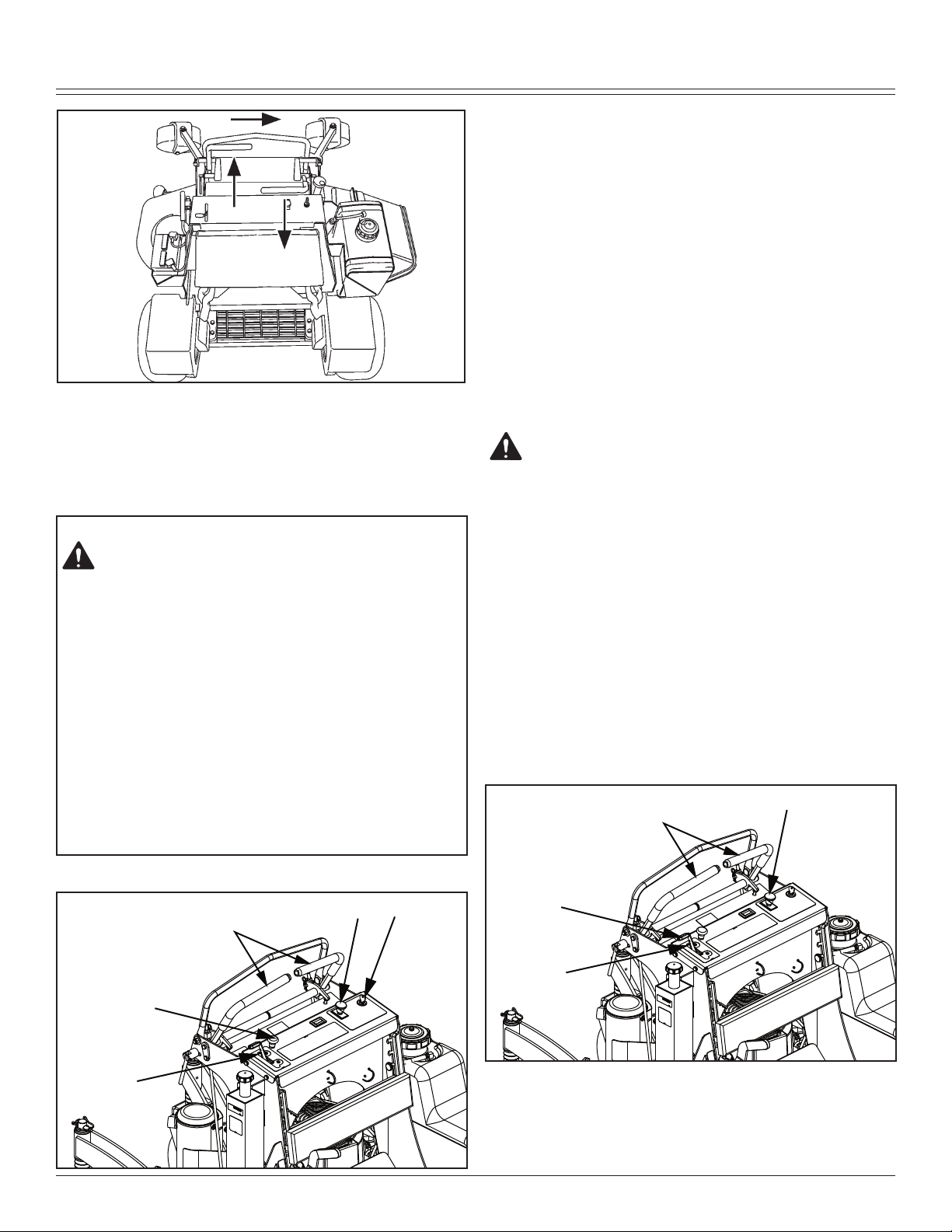
Loosen nuts (A).
2.
Adjust neutral switch (B).
3.
If neutral switch sensitivity needs to be increased,
•
adjust switch (B) down in slots.
If neutral switch sensitivity needs to be decreased,
•
adjust switch (B) up in slots.
4. Tighten nuts (A).
Service Steering & Brakes
Adjusting Park Brake
Testing Park Brake:
1. Inflate tires to correct pressures.
Picture Note: Battery Box and Battery removed for
clarity.
Remove rue clip (B).
3.
Turn brake linkage yoke in one-turn increments on the
4.
brake link rod (C) clockwise to increase braking force;
counterclockwise to decrease braking force.
Install rue clip (B).
5.
Test park brake. Adjust again, if required.
6.
2. Stop machine on a maximum 17° slope.
3. Lock park brake.
A properly adjusted park brake must prevent the drive
•
wheels from turning.
If the drive wheels turn, a brake adjustment will be
•
necessary.
Adjusting Park Brake:
Park machine safely. (Refer to Parking Safely in the
1.
SAFETY section.)
Unlock park brake.
2.
Service Mower
Removing and Installing Mower Deck Shield
CAUTION: Avoid injury! Help prevent serious
personal injury. Do not operate the mower without the mower deck shield installed.
Removing Mower Deck Shield:
1. Park machine safely. (See Parking Safely in the SAFETY
section.)
Remove two knobs (A).
2.
SERVICE MOWER - 28
Page 31

SERVICE MOWER
C
A
B
A
B
C
D
BELT ROUTING
201043
A
Lift shield (B) and pull forward to disengage from under
3.
tabs (C) on the frame.
Remove mower deck shield (B).
4.
CAUTION: Avoid injury! Help prevent serious
personal injury. Do not operate the mower without the belt shields installed.
Adjusting Drive Belt Tension
Park machine safely.
1.
Adjust mower deck to the 76 mm (3 in.) cutting height
2.
position.
Remove mower deck shield.
3.
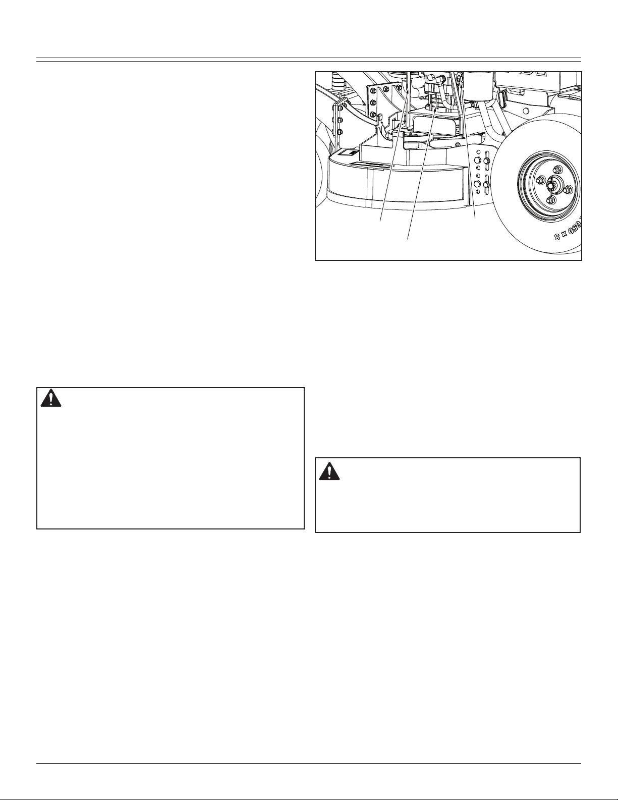
Release mower deck drive belt tension by turning ad-
5.
juster nut (A) counterclockwise until two threads remain
protruding through adjuster nut (A).
Disconnect idler spring (B) from idler arm (C) using a
6.
spring puller tool.
Remove mower deck drive belt (D).
7.
Measure length (C) of tension spring from inside of
4.
hook to inside of hook. The spring should measure 17.5
to 18.1 cm (6 7/8 in. to 7 1/8 in.).
To add tension to spring: Loosen jam nut (B). Turn
•
nut (A) clockwise. Tighten jam nut (B).
To release tension from spring: Loosen jam nut (B).
•
Turn nut (A) counterclockwise. Tighten jam nut (B).
Replacing Mower Deck Drive Belt
Removing Mower Deck Drive Belt:
Park machine safely. (See Parking Safely in the SAFE-
1.
TY section.)
Lower mower deck to the lowest cutting height position.
2.
Remove mower deck shield.
3.
Remove both mower deck belt shields.
4.
CAUTION: Avoid injury! Tensioning spring is
under high tension. Wear gloves and safety
glasses, and use a spring puller to install and
remove spring.
Installing Mower Deck Drive Belt:
NOTE: If necessary, see drive belt installation label on
mower deck.
Install replacement drive belt (A) as shown on mower
1.
deck drive belt label. Make sure drive belt is installed
properly on PTO clutch sheave, spindle sheaves and
idler pulleys.
SERVICE MOWER - 29
Page 32

SERVICE MOWER
C
A
B
A
B
C
Connect idler tension spring and adjust tension. The
2.
length (C) of the tension spring should measure 17.5
to 18.1 cm (6 7/8 in. to 7 1/8 in.) from inside of hook to
inside of hook.
Install both mower deck belt shields.
3.
Install mower deck shield.
4.
Adjust mower deck to desired cutting height.
5.
Checking for Bent Mower Blades
CAUTION: Avoid injury! Mower blades are
sharp. Always wear gloves when handling
mower blades or working near blades.
Replace blades if defective. Never straighten or weld them.
Park machine safely. (See Parking Safely in the
1.
SAFETY section.)
Raise mower to highest position to access blades.
2.
other blade tip and flat ground surface.
Install new blade if the difference between the two
5.
measurements is more than 3 mm (1/8 in.).
Repeat for all blades.
6.
Checking and Replacing Mower Blades
CAUTION: Avoid injury! Do not work near raised
mower deck unless it is safely supported.
Mower blades are sharp. Wrap blades or wear
•
gloves when servicing.
Before performing any service function, wait for
•
all moving parts to stop turning.
Disconnect battery or remove spark plug wire
•
before making repairs.
IMPORTANT: Avoid Damage! When replacing mower
blades, always use genuine Great Dane Service Parts.
NOTE: Only replace blades. Never straighten or weld
them.
Checking Mower Blades
Park machine safely. (See Parking Safely in the Safety
1.
Section).
Raise the mower deck to the transport position (also
2.
the 12.7 cm [5 in.] cutting height position).
Raise front of machine with a safe lifting device.
3.
Support with jack stands and/or wooden blocks.
•
4. Check mower blades:
• Mower blades should be sharp and free of any
damage.
• Inspect blades; sharpen/balance or replace as
necessary.
SERVICE MOWER - 30
Picture Note: Mower deck with side discharge used for
illustration.
Measure distance (A) between blade tip and flat ground
3.
surface.
Rotate blade 180° and measure distance between
4.
Replacing Mower Blades
Remove blade bolt (A), three 1/4 in. washers (B) and
1.
Page 33

SERVICE ELECTRICAL
A
B
blade (C).
Install replacement blade:
2.
Blade wing must face toward top of mower deck.
•
IMPORTANT: Avoid Damage! When installing the blade:
Make sure the blade is properly seated on the
•
spindle.
Make sure the concave side of the large washer
•
faces towards the blade.
Install blade bolt (A), blade (B) and three 1/4 in.
•
washers (C).
Tighten blade bolt to 163 N•m (120 lb-ft).
•
Lower machine.
3.
Adjust mower deck to a desirable cutting height.
4.
Sharpening Blades
CAUTION: Avoid injury! Mower blades are
dangerous!
Always wear gloves while working on blades.
•
Always wear safety eye protection when grinding.
•
Put blade on nail in a vise. Turn blade to horizontal
2.
position.
Check balance. If blade is not balanced, heavy end of
3.
blade will drop.
Grind bevel of heavy end. Do not change blade bevel.
4.
Service Electrical
• Sharpen blades with grinder, hand file, or electric blade
sharpener.
Keep original bevel (A) when grinding.
•
Blade should have 0.40 mm (1/64 in.) cutting edge (B)
•
or less.
Balance blades before installing.
•
Balancing Blades
CAUTION: Avoid injury! Mower blades are sharp.
Always wear gloves when handling mower blades or working near blades.
WARNING: Battery posts, terminals and related
accessories contain lead and lead components,
chemicals known to the State of California to cause
cancer and reproductive harm. Wash hands after
handling.
Service the Battery Safely
Clean blade.
1.
SERVICE ELECTRICAL - 31
Page 34

SERVICE ELECTRICAL
A
B
C
D
E
H
F
G
I
CAUTION: Avoid injury! Battery electrolyte
contains sulfuric acid. It is poisonous and can
cause serious burns:
Wear eye protection and gloves.
•
Keep skin protected.
•
If electrolyte is swallowed, get medical attention
•
immediately.
If electrolyte is splashed into eyes, flush
•
immediately with water for 15-30 minutes and
get medical attention.
If electrolyte is splashed onto skin, flush
•
immediately with water and get medical attention
if necessary.
The battery produces a flammable and
explosive gas. The battery may explode:
Do not smoke near battery.
•
Wear eye protection and gloves.
•
Do not allow direct metal contact across battery
•
posts.
Remove negative cable first when
•
disconnecting.
Install negative cable last when connecting.
•
Slide back black cover (A) and disconnect negative (-)
2.
battery cable (B).
Slide back red cover (C) and disconnect positive (+)
3.
battery cable (D).
Checking the Battery (Sealed Batteries)
NOTE: Do not attempt to open, add fluid or service battery. Any attempt to do so will void warranty.
• Keep battery and terminals clean.
• Keep battery bolts tight.
• Keep small vent holes open.
IMPORTANT: Avoid Damage! The battery comes fully
charged. If the machine is not used by the service expiration date indicated on the battery, charge the battery.
Recharge, if necessary, at 6–10 amperes for 1 hour.
Removing and Installing Battery
Removing:
Park machine safely. (See Parking Safely in the
1.
SAFETY section.)
SERVICE ELECTRICAL - 32
Loosen nut on front long carriage bolt (E).
4.
Remove rear long carriage bolt (F) and nut.
5.
Lift and slide battery (G) out from back of battery tray
6.
(H).
Inspect isolator pad (I). Replace as needed.
7.
Installing:
Place isolator pad (I) in battery tray (H). Ensure that
1.
isolator pad is on the bottom and sides of battery tray.
Install battery (G) in battery tray (H) with positive termi-
2.
nal in rear.
Install rear long carriage bolt (F) and nut. Do not over-
3.
tighten.
Tighten nut on long carriage bolt (E) to secure battery
4.
(G) in battery tray (H). Do not overtighten.
Apply dielectric grease to terminals to prevent corro-
5.
sion.
Connect the positive (+) battery cable (D) and install
6.
Page 35

SERVICE MISCELLANEOUS
A B
�
cover (C).
Connect negative (-) battery cable (B) and install cover
7.
(A).
Cleaning Battery and Terminals
Park machine safely. (See Parking Safely in the
1.
SAFETY section.)
Disconnect and remove battery.
2.
Wash battery with solution of four tablespoons of bak
3.
ing soda to one gallon of water. Be careful not to get
the soda solution into the cells.
Rinse the battery with plain water and dry.
4.
Clean terminals and battery cable ends with wire brush
5.
until bright.
Apply general purpose grease or silicone spray to ter-
6.
minal to prevent corrosion.
Install battery.
7.
Using Booster Battery
CAUTION: Avoid injury! The battery produces
a flammable and explosive gas. The battery
may explode:
Do not smoke or have open flame near battery.
•
Wear eye protection and gloves.
•
Do not jump start or charge a frozen battery.
•
Warm battery to 16°C (60°F).
Do not connect the negative (-) booster cable
•
to the negative (-) terminal of the discharged
battery. Connect at a good ground location
away from the discharged battery.
Connect positive (+) booster cable to booster battery
1.
(A) positive (+) post (C).
Connect the other end of positive (+) booster cable to
2.
the disabled vehicle battery (B) positive (+) post (D).
Connect negative (–) booster cable to booster battery
3.
negative (–) post (E).
IMPORTANT: Avoid Damage! Electric charge from
-
booster battery can damage machine components. Do
not install negative booster cable to machine frame.
Install only to the engine block.
Install negative booster cable away from moving parts in
the engine compartment, such as belts and fan blades.
Connect the other end (F) of negative (–) booster cable
4.
to a metal part of the disabled machine engine block
away from battery.
Start the engine of the disabled machine and run ma-
5.
chine for several minutes.
Carefully disconnect the booster cables in the exact
6.
reverse order: negative cable first and then the positive
cable.
Replacing Fuse
The electric start circuit is protected by one 20 Amp fuse.
IMPORTANT: Avoid Damage! Help prevent machine
circuit damage. Make sure replacement fuse is the
correct size.
Locate electric start fuse holder under console on the
1.
machine.
A - Booster Battery
B - Disabled Vehicle Battery
Open fuse holder (A) and remove socket with fuse.
•
Check metal clip in fuse window. Discard fuse if clip is
•
broken.
Install new 20 Amp fuse in socket.
•
Install socket with fuse in cover. Ensure that plastic tab
•
SERVICE MISCELLANEOUS - 33
Page 36

SERVICE MISCELLANEOUS
�
A
B
C
of fuse holder is securely fastened to fuse socket.
Adjusting Operator Presence Switch
Remove the OPC plate covering the operator presence
1.
switch by removing the two 3/8-16n1.25 carriage bolts
securing it in place.
Carefully cut the wire tie securing the harness to the
2.
plate.
not use fuel or additives containing methanol as engine
damage can occur.
Always use fresh, clean fuel that is purchased in a quantity
that can be used within approximately 30 days, or add fuel
stabilizer.
Fuel is blended to give best seasonal performance. To
avoid engine performance problems such as hard starting
or vapor lock, use in-season fuel. Use fuel during warm
weather that was purchased during that season, and use
fuel during cold weather that was purchased during that
season.
Fuel can become stale in machines with engines that are
used seasonally or infrequently during a season. Stale
fuel can produce varnish and plug carburetor components
which can affect engine performance.
Keep fuel storage container tightly covered and in a cool
area out of direct sunlight. Fuel can break down and degrade if not sealed properly or exposed to sun and heat.
Condensation may collect in the fuel tank because of a
variety of operating or environmental conditions and, over
time, may affect your machine’s operation. Fill fuel tank at
the end of daily use and store fuel in plastic containers to
reduce condensation.
Loosen the two # 10 pan head screws (A) securing the
3.
safety switch (B) in place and slide the switch in or out
as necessary.
Install the safety plate removed in step one and tie the
4.
harness to the plate again.
The switch is properly adjusted when there is 3/8” - 1/2”
clearance between the rubber bumper and the support
plate when there is not any pressure applied to the plate.
The foot plate can be adjusted by tightening or loosening
the lock nut (C) holding the compression spring in place.
Service Miscellaneous
Using Proper Fuel
Use regular grade unleaded fuel with an octane rating of 87
octane or higher. Fuel blends containing up to 10% ethanol
or up to 15% MTBE reformulated fuel are acceptable. Do
For best year-round performance and fuel-handling, add
stabilizer to fuel immediately after fuel purchase. Such
practice helps prevent engine performance problems and
allows fuel storage in the machine all year without draining.
Filling Fuel Tank
CAUTION: Avoid injury! Fuel vapors are
explosive and flammable:
Shut engine off before filling fuel tank.
•
Do not smoke while handling fuel.
•
Keep fuel away from flames or sparks.
•
Fill fuel tank outdoors or in well ventilated area.
•
Clean up spilled fuel immediately.
•
Use clean approved non-metal container to
•
prevent static electric discharge.
Use clean approved plastic funnel without
•
screen or filter to prevent static electric discharge.
SERVICE MISCELLANEOUS - 34
Page 37

SERVICE MISCELLANEOUS
�
B
C
Important: Avoid damage! Dirt and water in fuel can
cause engine damage:
Clean dirt and debris from the fuel tank
•
opening.
Use clean, fresh, stabilized fuel.
•
Fill the fuel tank at the end of each day’s
•
operation to keep condensation out of the fuel
tank.
Use a non-metallic funnel with a plastic mesh strainer
when filling the fuel tank or container.
Fill fuel tank at the end of each day’s operation to prevent
condensation and freezing during cold weather.
Park machine safely. (See Parking Safely in the
1.
SAFETY section.)
Allow engine to cool.
2.
Remove any trash from area around fuel tank cap.
3.
Remove fuel tank cap slowly to allow any pressure built
4.
up in tank to escape.
Fill fuel tank only to bottom of filler neck.
5.
Install fuel tank cap.
6.
Remove wheel nuts (B).
3.
Remove wheel.
4.
Installing:
Removing and Installing Rear Drive Wheels
Removing:
Park machine safely. (Refer to Parking Safely in the
1.
SAFETY section.)
Lift machine with a safe lifting device centered under
2.
tire support frame (A) on the side where tire is being
removed.
Install wheel with valve stem (C) facing out.
1.
Install and tighten wheel nuts alternately until recom-
2.
mended torque value is reached.
Tighten nuts to 102 N•m (75 lb-ft).
•
Lower machine.
3.
Removing and Installing Front Caster Wheels
Removing:
Park machine safely. (Refer to Parking Safely in the
1.
SAFETY section.)
Lift front of machine with a safe lifting device.
2.
Remove nut (A) and wheel cap screw (B).
3.
Remove wheel and spacers from yoke assembly (C).
4.
Installing:
Install replacement wheel and original spacers.
1.
Install wheel cap screw (B) and nut (A).
2.
Tighten nut until wheel develops slight rolling
3.
resistance.
Lower machine.
4.
Tightening Rear Drive Wheel Hardware
Tighten rear wheel nuts to 102 N•m (75 lb-ft).
1.
SERVICE MISCELLANEOUS - 35
Page 38

SERVICE MISCELLANEOUS
Tighten wheel nuts in numbered sequence shown for
2.
safe wheel installation. Tighten alternately until recommended torque value is reached.
Checking Tire Pressure
CAUTION: Avoid injury! Explosive separation
of tire and rim parts is possible when they are
serviced incorrectly:
Do not attempt to mount a tire without
•
the proper equipment and experience to
perform the job.
Do not inflate the tires above the recom-
•
mended pressure.
Do not weld or heat a wheel and tire as-
•
sembly. Heat can cause an increase in
air pressure resulting in an explosion.
Welding can structurally weaken or deform the wheel.
Do not stand in front or over the tire
•
assembly when inflating. Use a clip-on
chuck and extension hose long enough
to allow you to stand to one side.
Check tires for damage.
1.
Check tire pressure with an accurate gauge.
2.
Add air, if necessary:
3.
Tire Size Pressure
Front: 11 x 4 - 5
Rear: 18 x 6.5 - 8 69–97 kPa (10–14 psi)
138–173 kPa (20-25 psi)
Servicing Caster Wheel Roller Bearings
Park machine safely. (See Parking Safely in the
1.
SAFETY section.)
Raise and securely support front of machine.
2.
SERVICE MISCELLANEOUS - 36
Page 39

TROUBLESHOOTING
Cleaning and Repairing Metal Surfaces
Cleaning:
Follow automotive practices to care for your vehicle painted
metal surfaces. Use a high-quality automotive wax regularly to maintain the factory look of your vehicle’s painted
surfaces.
Repairing Minor Scratches (surface scratch):
Clean area to be repaired thoroughly.
1.
Remove locknut (A), cap screw (B), and wheel assem-
3.
bly (C).
Remove seals (D) and bearings (E) from wheel.
4.
Clean and inspect bearings (E). Replace as needed.
5.
Repack bearings with clean grease.
6.
Install bearings (E) and wheel spacer (F) (if removed),
7.
and new seals (D).
Install wheel assembly (C), cap screw (B) and locknut
8.
(A).
Use a grease gun to fill hub until grease just appears at
9.
one of the seals (D).
Lower machine.
10.
Cleaning and Repairing Plastic Surfaces
Your authorized dealer has the professional materials needed to properly remove surface scratches from any plastic
surfaces, do not attempt to paint over marks or scratches in
plastic parts.
IMPORTANT: Avoid Damage! Improper care of machine
plastic surfaces can damage that surface:
Do not wipe plastic surfaces when they are
•
dry. Dry wiping will result in minor surface
scratches.
Use a soft, clean cloth (bath towel, diaper,
•
automotive mitt).
Do not use abrasive materials, such as pol-
•
ishing compounds, on plastic surfaces.
Do not spray insect repellent near machine.
•
Wash surface with clean water and a mild liquid auto-
1.
motive washing soap.
Dry thoroughly to avoid water spots.
2.
TROUBLESHOOTING - 37
IMPORTANT: Avoid damage! Do not use rubbing com
pound on painted surfaces.
Use automotive polishing compound to remove surface
1.
scratches.
Apply wax to entire surface.
2.
Repairing Deep Scratches (bare metal or primer showing):
Clean area to be repaired with rubbing alcohol or min-
1.
eral spirits.
Use paint stick with factory-matched colors available
2.
from your authorized dealer to fill scratches. Follow
directions included on paint stick for use and for drying.
Smooth out surface using an automotive polishing
3.
compound. Do not use power buffer.
Apply wax to surface.
4.
-
Troubleshooting
Using Troubleshooting Chart
If you are experiencing a problem that is not listed in this
chart, see your authorized dealer for service.
When you have checked all the possible causes listed and
you are still experiencing the problem, see your authorized
dealer.
If Check
Poor Engine
Performance
Fuel:
• Dirt in fuel system or fuel is
old. Replace fuel with fresh
stabilized fuel. Obtain fuel
from another supplier before
suspecting machine problems.
Suppliers blend fuels differently
and changing suppliers will
generally solve any performance
problems.
• Fuel blended with alcohol or ether
may contribute to performance
problems by causing gum and
varnish deposits, especially if
fuel is stored for several weeks
or more. Obtain fresh fuel.
Page 40

STORAGE
Engine Will Not Start
Or Is Hard To Start
Engine Will Not Slow
Idle
Engine Runs Rough
or Stalls
Engine Knocks • Engine oil level low.
Engine Overheats • Clean cooling fins.
• Park brake lever not in the proper
position.
• OPC switch not depressed. Stand
on platform or adjust switch.
• Check that motion control levers
are in neutral and neutral
switches are correctly adjusted.
• PTO engaged.
• Stale or improper fuel/fuel level.
• Plugged fuel filter.
• Plugged air intake filter.
• Spark plug wires loose or
disconnected.
• Spark plugs not gapped correctly.
• Blown fuse.
• Electrical problem – dead battery.
• Choke adjusted incorrectly. See
your authorized dealer.
• Carburetion problems. See your
authorized dealer.
• Bent or kinked throttle cable.
• Bent governor control.
• Incorrect governor idle control.
• Plugged fuel filter.
• Plugged air intake system.
• Fuel cap vent dirty.
• Stale or improper fuel/fuel level.
• Spark plugs not gapped correctly.
• Replace spark plugs.
• Choke adjusted incorrectly. See
your authorized dealer.
• Reduce load. (Slower ground
speed.)
• Fuel is bad. Fill tank with fresh
fuel, correct octane.
• Idle speed too slow.
• Low oil level.
• Do not operate at slow idle.
Operate at fast idle.
• Cooling air intake screen is dirty.
• Plugged carburetor air intake
filter.
• Plugged air intake filter.
• Operating at too fast ground
speed for conditions.
Engine Lacks Power • Reduce load.
• Plugged air intake system.
• Plugged fuel filter.
• Improper type of fuel. Drain tank
and fill with correct fuel.
• Clean cooling fins to help prevent
overheating.
• Replace spark plugs.
Engine Uses Too
Much Oil
Engine Backfires
Through Muffler
High Fuel
Consumption
Other Symptoms • See engine manufacturer’s
• Find and correct oil leaks.
• Incorrect engine oil.
• Plugged oil filter.
• Plugged air intake filter.
• Worn engine components.
• Throttle lever should be at low
idle for thirty seconds before
turning off machine.
• Improper type of fuel.
• Plugged air intake system.
• Operating at too fast ground
speed for conditions.
• Improper valve clearance. See
your authorized dealer.
• Restricted air intake system.
owner’s manual provided with
your machine for additional
information.
Electrical System
If Check
Starter Will Not Work
• Blown fuse.
• OPC Switch faulty or not adjusted
properly.
• Park brake switch is faulty.
• Loose or corroded battery
connections.
STORAGE - 38
Page 41

STORAGE
• Neutral switches faulty or not
adjusted properly. See your
authorized dealer.
• Key switch or starter faulty. See
your • authorized dealer.
• PTO engaged.
• Motion control levers and park
brake lever not in proper
position.
Battery Will Not
Charge
PTO Switch Does
Not Work
Starter Turns Slowly • Loose or corroded battery
• Loose or corroded connections.
• Blown fuse or fusible link. See
your authorized dealer.
• Blown fuse.
• PTO switch faulty.
connections.
• Low battery power-charge
battery.
• Engine oil viscosity too heavy.
• Hydraulic pump linkage out of
adjustment-pumps engaged.
Machine
Machine Creeps
With Engine
Running and Motion
Control Levers in a
Neutral Position
• Needs motion control linkage
adjustment.
• Needs Adjustment.
Park Brake
If Check
Park Brake Not
Working Correctly
Steering
If Check
Steering Not
Working
• Park brake out of adjustment
– adjust linkage.
• Pump free-wheel valves partially
open.
• Improper tire inflation.
• Hydrostatic transmission oil level
low.
• Traction drive loose or broken.
• Hydraulic pump or wheel motor
faulty.
If Check
Excessive Machine
Vibration
Machine Will Not
Move With Engine
Running
• Engine speed too slow.
• Deck drive belt not tensioned
correctly.
• Mower blades not balanced.
• Park brake locked.
• Transmission oil level low.
• Transmission oil cold – allow
engine to warm up.
• Pump drive belt slipping or
broken.
• Pump drive belt spring broken.
• Pump free-wheel valves open.
• Transmission problems. See your
authorized dealer.
Mower Deck
If Check
Discharge Chute
Plugged
Mower Deck
Vibrates
• Grass is wet-mow grass only
when dry.
• Raise cutting height.
• Mow with engine at full fast
throttle.
• Ground speed too fast for
conditions.
• Correct installation of deck drive
belt.
• Run engine at fast throttle.
• Loose hardware.
• Check/replace deck drive belt.
• Blade bolts are loose.
• Blades are bent or worn.
• Sharpen and balance blades.
STORAGE - 39
Page 42

ASSEMBLY
Mower Blades Do
Not Engage
Mower Mows
Unevenly
Storage
Storing Safety
• Remove belt shields and clean
debris from sheaves.
• Check sheaves for proper
alignment or damage. See
authorized dealer.
• Deck drive belt slipping or broken.
• Deck belt tension spring not
installed or broken.
• PTO switch faulty.
• Fuse blown.
• Loose electrical connections.
• PTO clutch faulty.
• Mower deck not properly leveled.
• Ground speed too fast for
conditions.
• Run engine at fast throttle.
• Reduce ground speed when
making turns.
• Sharpen or replace blades.
• Change mowing pattern.
• Check air pressure in all traction
unit tires.
• Anti-scalp rollers not adjusted
correctly.
from inside chute and bagger.
Wash the machine and apply wax to metal and plastic
5.
surfaces.
Run machine for five minutes to dry belts and pulleys.
6.
Apply light coat of engine oil to pivot and wear points to
7.
prevent rust.
Lubricate grease points and check tire pressure.
8.
Preparing Fuel and Engine For Storage
Fuel:
If you have been using “Stabilized Fuel,” add stabilized fuel
to tank until the tank is full.
NOTE: Filling the fuel tank reduces the amount of air in the
fuel tank and helps reduce deterioration of fuel.
If you are not using “Stabilized Fuel:”
Park machine safely in a well-ventilated area. (See
1.
Parking Safely in the SAFETY section.)
NOTE: Try to anticipate the last time the machine will
be used for the season so very little fuel is left in the
fuel tank.
Turn on engine and allow to run until it runs out of fuel.
2.
For machines equipped with key switch, turn key to off
3.
position.
IMPORTANT: Avoid Damage! Stale fuel can produce
varnish and plug carburetor or injector components
and affect engine performance.
Add fuel conditioner or stabilizer to fresh fuel before
•
filling tank.
Mix fresh fuel and fuel stabilizer in separate container.
4.
Follow stabilizer instructions for mixing.
Fill fuel tank with stabilized fuel.
5.
Run engine for a few minutes to allow fuel mixture to
6.
circulate through carburetor on gas engine or fuel injectors on diesel engine.
CAUTION: Avoid injury! Fuel vapors are ex-
plosive and flammable. Engine exhaust fumes
contain carbon monoxide and can cause serious illness or death:
Run the engine only long enough to move the machine to
or from storage.
Do not store vehicle with fuel in the tank inside a building
where fumes may reach an open flame or spark.
Allow the engine to cool before storing the machine in any
enclosure.
Preparing Machine for Storage
Repair any worn or damaged parts. Replace parts if
1.
necessary. Tighten loose hardware.
Repair scratched or chipped metal surfaces to prevent
2.
rust.
Remove grass and debris from machine.
3.
Clean under the deck and remove grass and debris
4.
ASSEMBLY - 40
Engine:
Engine storage procedure should be used when vehicle is
not to be used for longer than 60 days.
Change engine oil and filter while engine is warm.
1.
Service air filter if necessary.
2.
Clean debris from engine air intake screen.
3.
On gas engines:
4.
Remove spark plugs. Put 30 mL (1 oz) of clean engine
•
oil in cylinders.
Install spark plugs, but do not connect spark plug wires.
•
Crank the engine five or six times to allow oil to be
•
distributed.
Clean the engine and engine compartment.
5.
Remove battery.
6.
Clean the battery and battery posts. Check the electro-
7.
lyte level, if your battery is not maintenance free.
Close fuel shut-off valve, if your machine is equipped.
8.
Store the battery in a cool, dry place where it will not
9.
freeze.
Page 43

SPECIFICATIONS
A
B
C
A
B
�
NOTE: The stored battery should be recharged every 90
days.
Charge the battery.
10.
IMPORTANT: Avoid Damage! Prolonged exposure to
sunlight could damage the hood surface. Store machine inside or use a cover if stored outside.
Store the vehicle in a dry, protected place. If vehicle is
11.
stored outside, put a waterproof cover over it.
Removing Machine From Storage
Check tire pressure.
1.
Check engine oil level.
2.
Check battery electrolyte level, if your battery is not
3.
maintenance free. Charge battery if necessary.
Install battery.
4.
On gas engines: Check spark plug gap. Install and
5.
tighten plugs to specified torque.
Lubricate all grease points.
6.
Open fuel shut-off valve, if your machine is equipped.
7.
Run the engine 5 minutes without the mower or any at-
8.
tachments running to allow oil to be distributed throughout engine.
Be sure all shields and guards or deflectors are in
9.
place.
Assembly
Connect Handles
Check Hydraulic Oil Level
Clean area around dipstick cap (A).
1.
Remove dipstick cap (A). Wipe dipstick clean.
2.
NOTE: Do not tighten dipstick cap when checking oil
level.
Insert dipstick in filler neck (B). Do not tighten cap.
3.
Remove dipstick. Check oil level on dipstick. Oil level
4.
should be between the ADD and FULL marks on dipstick.
If oil is level is below ADD mark, fill to proper
•
level.
If oil level is above FULL mark, drain to proper
•
level.
Insert dipstick. Tighten cap.
5.
The handles are disconnected and rotated forward during assembly to allow for proper fitment into the shipping
container.
Rotate the handles up.
1.
Connect the pump control arm (C) to the handle
2.
weldment by inserting the adjustment block (A) into the
handle weldment and securing with the hairpin clip (B).
Set the speed control bar to desired speed and lock.
3.
Check Engine Oil Level
1.
SPECIFICATIONS - 41
2.
NOTE: Do not tighten dipstick cap when checking oil
level.
3.
4.
Clean area around dipstick cap (A).
Remove dipstick cap (A) from tube. Wipe dipstick
clean.
Insert dipstick in tube. Do not tighten cap.
Remove dipstick. Check oil level on dipstick. Oil level
should be between the ADD and FULL marks.
Page 44

If oil is level is below ADD mark, fill to proper
•
level.
If oil level is above the FULL mark, drain to
•
proper level.
Insert dipstick. Tighten cap.
5.
GETTING QUALITY SERVICE
Tires
Rear.................................................................18 x 6.5 - 8
Front...................................................................11 x 4 - 5
Inflation Rear (Maximum)..............69–97 kPa (10–14 psi)
Inflation Front (Maximum)..........138–173 kPa (20-25 psi)
Connect Battery
CAUTION: Avoid injury! Prevent Battery Explosions:
• Keep sparks, lighted matches, and open flame away from
the top of battery. Battery gas can explode.
• Never check battery charge by placing a metal object
across the posts. Use a volt-meter or hydrometer.
• Do not charge a frozen battery; it may explode. Warm battery to 16 degrees C (60 degrees F).
Connect positive (red) cable to battery positive (+)
1.
terminal. Install red terminal cover (A).
Connect negative (black) cable to battery negative (-)
2.
terminal. Install black terminal cover (B).
Check Machine Safety Systems
Perform safety system check to make sure the electronic
safety interlock circuit is functioning properly.
Specifications
Engine
Note: See engine manufacturer’s owner’s manual provided
with your machine for engine specifications.
Drivetrain
Type........................................................ Dual Hydrostatic
Pumps.........Hydro-Gear PG-1KDA-D61 - PG-1HDA-D41
Wheel Motors..........................Hydro-Gear HGD-12-7172
Number of Speeds.................................Infinitely Variable
Electrical System
Charging System..................................................15 Amp
Ignition................................................................Flywheel
Starter.........................................................Solenoid Shift
Fuel System
Fuel Type..............................Gasoline, Regular Unleaded
Fuel Tank Location...................On Right Side of Operator
Fuel Capacity ............................................22.7 L (6.0 gal)
Steering and Brakes
Steering.............................................Dual Control Levers
Steering..............................................................Hydraulic
Park Brake.....................................................Tire Contact
Battery
Voltage....................................................................12-volt
CCA.....................................................................270-amp
Reserve Capacity.............................................67 minutes
BCI Group Size.............................................................U1
Capacities
Fuel Tank......................................................18.9 L (5 gal)
Hydraulic Oil (With Filter) 3.1 L (3.3 qt.)
Engine Oil (With Filter) 1.9 L (2.0 qt.)
Travel Speeds at Full Engine RPM
Forward........................................0–14 km/h (0–8.7 mph)
Reverse..........................................0–6.4 km/h (0–4 mph)
Dimensions
Overall Height............................................1.47 m (47 in.)
Overall Length.........................................1.48 m (58.5 in.)
Overall Width (with chute up)....................... .89 m (35 in.)
Overall Width (with chute down).................1.19 m (47 in.)
Recommended Lubricants
Engine Oil.........................See Applicable Engine Manual
Hydraulic Oil................5W-50 or 15W-50 All Synthetic Oil
Grease: (This may change for high-speed applications such
as cutting units)
All-Purpose Grease with an NLGI Grade No. 2 Rating
(Specifications and design subject to change without
notice.)
Getting Quality Service
Service Literature
If you would like to order a copy of the Parts Catalog or
Operator Manual for this machine, contact your Great Dane
Dealer. Parts catalogs and operator manuals are also available online at Great Dane.com.
Parts
We recommend Great Dane quality parts available at your
Great Dane dealer.
Part numbers may change, use part numbers listed below
when you order. If a number changes, your dealer will have
the latest number.
When you order parts, your Great Dane dealer needs your
machine serial number and engine serial number. These
are the numbers that you recorded in the Product Identification section of this manual.
GETTING QUALITY SERVICE - 42
Page 45

GETTING QUALITY SERVICE
Great Dane Quality Continues with Quality Service
Great Dane provides a process to handle your questions or
problems, should they arise, to ensure that product quality
continues with your authorized Great Dane dealer’s parts
and service support.
Follow the steps below to get answers to any questions you
may have about your product.
Refer to your attachment and machine operator manuals.
Contact your authorized Great Dane dealer with unanswered questions.
Part Numbers
Item Part Number
Mower Blades:
34-Inch Deck - LH Blade GDU10231
34-Inch Deck - RH Blade GDU10230
Hydraulic Oil Filter GDU10137
Battery 191832
Fuse - 20 amp 57M7120
Belts:
Hydraulic Drive Belt 201009
34-Inch Mower Deck Belt 201010
(Part numbers are subject to change without notice. Part
Numbers may be different outside the U.S.A.)
GETTING QUALITY SERVICE - 43
Page 46

GY
R
R
TN
GN
Y
W
Y
W
LT/GN
LT/GN
LT/GN
LT/GN
LT/BU
GY GRAY
TN TAN
PK PINK
LT/BU LIGHT BLUE
LT/GN LIGHT GREEN
GN GREEN
BU BLUE
V VIOLET
Y YELLOW
OR ORANGE
R RED
BN BROWN
BK BLACK
W WHITE
W
ENGINE KILL
GY
LT/GN
TN
GY
PTO SWITCH
STARTER SOLINOID
BK
87
BU
30
BK/OR
Y
VOLTAGE REGULATOR
86
85
BK
V
CLUTCH
BN
D
D
RIGHT SAFETY
Y
PK
D
LEFT
SAFETY
OR
OPERATOR PRESENCE SWITCH
OR
S
B
L
OR
G
M
85
86
BK
87
W
W
N
D
D
D
W
GY
30
87a
R
OR
85
86
BK
+
R
FUEL
SOLENOID
BK
BK
-
BK
BATTERY
20 AMP
FUSE
30
D
D
D
P
P
D
BK
HAND BRAKE
HOUR METER
BK
87
BK
86
IGN KILL RELAY
CLUTCH RELAY
START RELAY
P
D
N
N
N
BK
BK
V
W
W
WIRING DIAGRAM
Wiring Diagram - 44
Page 47

HYDRAULIC SCHEMATIC
Hydraulic Schematic - 45
Page 48

NOTES
Notes - 46
Page 49

963019
10
964016
6
964003
4
960022
6
960601
6
TCU21265
1
M68342
2
201005
1
960001
2
963001
2
964040
4
201019
1
201355
1
960044
2
967115
10
201150
2
960526
8
Battery
1
964040
4
201012
1
963019
10
D28159
1
03H1832
2
968087
4
967115
10
201356
1
201095
1
201204
1
201094
1
960027
4
960031
4
201202
1
960601
6
960022
6
181148
1
201194
2
201328
1
201090
2
960113
6
135139
4
963019
10
967192
6
251907
1
200658
1
964003
4
201331
1
MAIN FRAME ASSEMBLY
Frame Assembly - 46
Page 50

MAIN FRAME ASSEMBLY
PART NO QTY DESCRIPTION
D28159 1 STRIP, BATTERY INSULATOR
M68342 2 CLAMP, HOSE (RED) #
TCU21265 1 HOSE, 1/4" ID LOW PERM FUEL 50
03H1832 2 BOLT, 5/16-18 X 6.00 CRG 2 Y
135139 4 BOLT, 1/2 X 1.06 X 3/8-16 SLD 5 Y
181148 1 CABLE, BATTERY STARTER - 48"
BATTERY 1 BATTERY, 12V-U1-CCA270MIN
200658 1 PIN, CVS SPG 3/8" YOKE SPEC Y
201005 1 TANK, FUEL PUPPY PAW ASSEMBLY
201012 1 WLDT, RESERVIOR GUARD
201019 1 CABLE, BATTERY - 25" GROUND
201356 1 CONSOLE BATTERY BRACKET
201090 2 LATCH, BECKSON
201331 1 SHIELD, LH PUMP
201328 1 SHIELD, RH PUMP
201094 1 SHIELD, RH MOTOR
201095 1 SHIELD, LH MOTOR
201150 2 ASSY, TIRE/WHL 18/6.5X8 SLVR
201355 1 SHIELD, ENGINE
201194 2 ROD, CONTROL 5/16 X 22.75 Y
201202 1 RH CAST WEIGHT MACHINED
201204 1 LH CAST WEIGHT MACHINED
251907 1 YOKE, 3/8-24 RH ADJUSTABLE
960001 2 BOLT, 1/4-20 X .750 HEX 5 Y
960022 6 BOLT, 5/16-18 X .750 HEX 5 Y
960027 4 BOLT, 5/16-18 X 2.00 HEX 5 Y
960031 4 BOLT, 5/16-18 X 3.00 HEX 5 Y
960044 2 BOLT, 3/8-16 X 1.00 FGH 8 Y
960113 6 BOLT, 1/2-13 X 1.25 HEX 5 Y
960526 8 NUT, 1/2-20 LUG C
960601 6 WASHER, .313 MED SPRG LOCK Y
963001 2 BOLT, 1/4-20 X .625 WSH Y
963019 10 BOLT, 3/8-16 X 1.00 CRG 5 SN Y
964003 4 NUT, 5/16-24 STD HEX GR5 Y
964016 6 LOCKNUT, 3/8-16 WHIZ Y
964040 4 LOCKNUT, 1/4-20 WHIZ Y
967115 10 LOCKNUT, 5/16-18 NYLOC Y
967192 6 LOCKNUT, 1/2-13 WHIZ GR5 Y
968087 4 LOCKNUT, 3/8-16 NYLOC Y
Frame Assembly - 47
Page 51

HYDRAULIC AND HANDLE ASSEMBLY
960001
7
960600
6
201358
1
201359
1
200116
4
D13028
2
121080
3
963020
4
200654
1
TCA15195
1
960001
7
968087
6
960702
4
D13309
1
34H60
1
TCA15122
1
964048
3
180640
1
960002
2
201354
1
960000
2
121080
3
201022
1
D18079
1
960001
7
200690
1
200606
1
200671
1
200615
1
201354
1
963053
1
200705
1
GDA10066
1
960046
2
313270
1
GDA10137
1
TCA15373
1
968087
6
960702
4
968087
6
M117554
1
D18023
1
D24028
1
201197
1
180842
1
201197
1
D24020
3
M63431
3
960600
6
102770
3
960500
2
960001
7
960600
6
200743
1
Hydraulc and Handle Assembly - 48
Page 52

HYDRAULIC AND HANDLE ASSEMBLY
PART NO
D13028 2 SWIVEL ADJUSTER
D13308 1 BASE, LOCK LEVER Y
D13309 1 LEVER, LOCK Y
D18023 1 DECAL, HYDRO OIL SPECS.
D18079 1 GRIP, PVC .250 X 1.00 X 3.63
D18093 2 GRIP, CONTROL
D24020 3 SCREW, 8-32X .50 PAN PHL Y
D24028 1 FTG, 90 9/16 MOR X 3/8 HOSE
GDA10066 1 ELBOW, FITTING
GDA10137 1 FILTER, OIL
M117554
M63431 3 NUT, 8-32 ELASTIC STOP
TCA15122 1 CAP, FILLER OIL
TCA15195 1 WLDT, PIVOT ROD Y
TCA15373 1 WLDT, RESERVIOR HYDRAULIC
TCU15907 1 DECAL, WARNING, SLOPE
TCU15910 1 DECAL, DIRECTIONAL CONTROL
102770 3 RELAY, ISO MINI ELEC.
111910
121080 3 PIN, HAR .091 X 1.63 5/16-1/2 Y
180640 1 SOLENOID, 12 V STARTER
180842 1 CABLE, 12" STARTER
200037 1 DECAL, PATENT COVERED
200116
200606 1 PAD, THIGH
200615 1 LINK. BRAKE Y
200743 1 CONTROL PANEL S/O
200654 1 HANDLE, SUPPORT
200671 1 BUSHING, BRAKE PIVOT Y
200690 1 WLDT, THIGH PAD BRACKET
200705 1 SWITCH, NO-NO-NC GREY PLUNGER
201022 1 BRAKE LEVER, OFFSET
201354 1 WLDT, CONSOLE 34
201358 1 WLDT, RH CONTROL LEVER
201359 1 WLDT, LH CONTROL LEVER
201197
313270 1 FTG, 90 9/16 MOR X 9/16 MJIC
34H60 1 PIN, SPRING
960000 2 BOLT, 1/4-20 X .500 HEX 5 Y
960001 7 BOLT, 1/4-20 X .750 HEX 5 Y
960002 2 BOLT, 1/4-20 X 1.00 HEX 5 Y
960046 2 BOLT, 3/8-16 X 1.00 HEX 5 Y
960500 2 NUT, 1/4-20 STD HEX GR5 Y
960600 6 WASHER, .250 MED SPRG LOCK Y
960702 4 WASHER, .375 REG FLAT Y
963020 4 BOLT, 3/8-16 X 1.00 CRG 5 Y
963053 1 BOLT, 3/8-16 X 1.25 CRG 5 Y
964048 3 LOCKNUT, 1/4-20 NYLOC Y
968087 6 LOCKNUT, 3/8-16 NYLOC Y
QTY DESCRIPTION
1 DECAL, WARNING - HOT SURFACES
3 CABLE TIE, .15 X 8.50
4 BRG, FLG .500X.620X.500 BRNZ
1 HARNESS, WIRING
Hydraulc and Handle Assembly - 49
Page 53

ENGINE, HYDRAULIC AND MAINFRAME ASSEMBLY
D14252
1
960602
1
D18056
1
200665
1
200318
1
967115
6
960052
1
964001
1
403490
1
150052
1
191179
2
D18071
1
201143
1
191179
2
D18314
1
960049
1
968087
12
968087
12
960702
3
968087
12
963033
2
960502
1
111910
4
200769
1
231104
2
TCA15078
2
231647
2
960046
10
200959
2
24M7158
2
11H237
2
201027
1
TCA16240
1
967115
6
967034
1
967115
6
963053
4
968087
12
D14213
2
TCA15316
2
D18067
2
201025
1
967155
1
964013
2
D38128
1
2007701960055
1
d18038
1
201353
1
967340
2
M117554
2
TCA15078
2
GDA10004
1
959995
2
963020
2
960026
1
960025
3
D14160
2
200666
1
960022
2
960078
1
231046
2
201091
4
231046
2
201091
4
201206
1
959995
2
111910
4
968087
12
960702
3
D18145
1
M86863
2
DT5332
1
D18379
12
111910
4
201206
1
200958
2
967370
8
Engine, Hydraulic And Mainframe Assembly - 50
Page 54

ENGINE, HYDRAULIC AND MAINFRAME ASSEMBLY
PART NO
DT5332 1 HOSE, 3/8 SAE30R7 FUEL & OIL
D14160 2 WASHER, .250 WIDE HEAVY FLAT Y
D14213 2 BOLT, M6 X 1.00 X 10 HEX 8.8 Y
D14252 1 BOLT, 7/16-20X3.00 HEX 5 Y
d18038 1 SWITCH (N.0.)
D18056 1 SPACER, .468 X 1.38 X .375 Y
D18067 2 KEY, M5 X M5 X M30 RD
D18071 1 SPRING, EXT .900X.135X4.50 Y
D18314 1 PULLEY, V-BELT 4.00X.379 W/BRG
D18379 12 CLAMP, HOSE - 1/2" PINCH
D38128 1 SPRING, COM 1.22X.162X2.50 Y
GDA10004 1 WLDT, PIVOT IDLER MOUNT
M117554 2 DECAL, WARNING - HOT SURFACES
M86863 2 FTG, TUN 3/8 HOSE
TCA15078 2 MOTOR, WHEEL HGM-12P-7172
TCA15316 2 ASSY, PUMP PULLEY W/SET SCREW
TCA16240 1 FITTING, OIL DRAIN
11H237 2 PIN, COT .125 X 2.00 EXTP Y
111910 4 CABLE TIE, .15 X 8.50
150052 1 BUSHING, MACH .750X1.25X.048 Y
191179 2 BRG, FLG .750 X 1.00 X .750 BRNZ
200318 1 PULLEY, V-BELT 4.78PD X 1.000 W/KEY
200665 1 CLUTCH ASSY, OGURA
200666 1 PLATE, CLUTCH DOG
200769 1 COVER, OPC
200770 1 WASHER, SPRING Y
200958 1 WHEEL HUB, MACHINED
200959 2 ASSY, REAR WHEEL HUB (Includes 20958 & 967370)
201009 1 BELT, HA 68.2 EL AMD OHR
201025 1 WLDT, RH BRAKE ARM
201027 1 WLDT, LH BRAKE SHAFT
201091 4 HOSE, HYD 1/2 X 26 1/2 EZFLEX
201353 1 WLDT, FRAME 34
201143 1 WLDT, IDLER PIVOT
201206 1 ABRASION SLEEVE
231046 2 FTG, ADP MJIC-FSWJIC 6500-08-08
231104 2 FTG, ADP 3/4-16FJIC X 7/8-14MOR
231647 2 FTG, ADP JIC-ORB 2062-10-8S
24M7158 2 SHIM, .020X.787X1.102
403490 1 SNAP RING, .750 X .042 EXT
959995 2 FTG, 1/4-28 STRGT GREASE ZERK
960022 2 BOLT, 5/16-18 X .750 HEX 5 Y
960025 3 BOLT, 5/16-18 X 1.50 HEX 5 Y
960026 1 BOLT, 5/16-18 X 1.75 HEX 5 Y
960046 10 BOLT, 3/8-16 X 1.00 HEX 5 Y
960049 1 BOLT, 3/8-16 X 1.75 HEX 5 Y
960052 1 BOLT, 3/8-16 X 2.50 HEX 5 Y
960055 1 BOLT, 3/8-16 X 3.25 HEX 5 Y
960078 1 BOLT, 7/16-14 X .750 HEX 5 Y
960502 1 NUT, 3/8-16 STD HEX GR5 Y
960602 1 WASHER, .375 MED SPRG LOCK Y
960702 3 WASHER, .375 REG FLAT Y
963020 2 BOLT, 3/8-16 X 1.00 CRG 5 Y
963033 2 Bolt,3/8-16x3/4 Car Gr5 LNnk
963053 4 BOLT, 3/8-16 X 1.25 CRG 5 Y
964001 1 NUT, 3/8-16 JAM GR5 Y
964013 2 LOCKNUT, 10-24 NYLOC Y
967034 1 NUT, 5/16-18 JAM GR5 Y
967115 6 LOCKNUT, 5/16-18 NYLOC Y
967155 1 PIN, ROL .156 X 1.00
967340 2 SCREW, 10-24 X .625 PAN PHL MAC Y
967370 8 BOLT, 1/2-20 x 1.66 SPC
968087 12 LOCKNUT, 3/8-16 NYLOC Y
D18145 1 KEY, .250 X .250 X .995 TPR
QTY DESCRIPTION
Engine, Hydraulic And Mainframe Assembly - 51
Page 55

FOOT PLATE/CONSOLE COMPONENTS
960001
4
200619
1
200767
1
963074
2
201136
1
200655
2
967115
2
960701
2
200693
1
968087
4
963019
4
964048
4
TCU16481
TCU14840
D18021
180620
1
200607
1
136574
1
192296
1
D18427
1
D24020
2
TCA15051
1
M63431
2
200780
1
14H846
1
105684
1
FOOT PLATE COMPONENTS
CONSOLE COMPONENTS
Foot Plate/Console Components - 52
Page 56

FOOT PLATE/CONSOLE COMPONENTS
FOOT PLATE COMPONENTS
PART NO QTY DESCRIPTION
200619 1 PLATE, PLATFORM TAB LH
200655 2 BUMPER, MINER GBR-6
200693 1 PLATE, PLATFORM TAB
200767 1 ANCHOR, OPC
201136
960001 4 BOLT, 1/4-20 X .750 HEX 5 Y
960701 2 WASHER, .313 REG FLAT Y
963019 4 BOLT, 3/8-16 X 1.00 CRG 5 SN Y
963074 2 BOLT, 5/16-18 X 1.00 CRG 2 Y
964048 4 LOCKNUT, 1/4-20 NYLOC Y
967115
968087 4 LOCKNUT, 3/8-16 NYLOC Y
1 PLATFORM
2 LOCKNUT, 5/16-18 NYLOC Y
CONSOLE COMPONENTS
PART NO
D18021 1 DECAL, THROTTLE
D18427 1 CABLE, CHOKE
D24020 2 SCREW, 8-32X .50 PAN PHL Y
M63431 2 NUT, 8-32 ELASTIC STOP
TCA15051 1 CABLE, THROTTLE
TCU14840 1 DECAL, GENERAL CAUTION
TCU16481 1 DECAL, PTO & KEY SWITCH
105684 1 KEY
136574 1 SWITCH, PTO ENGAGEMENT
14H846 1 NUT, 3/8 UNF HEX GR 5 ZN
180620 1 SWITCH, KEY - 3 POSITION
192296 1 METER, HOUR - LCD ALT. (ENM)
200743 1 TOP, CONSOLE W/DECALS
QTY DESCRIPTION
Foot Plate/Console Components - 53
Page 57

DECK ASSEMBLY
201174
2
967348
2
GDU10231
1
D18055
6
200262
2
960046
16
964016
17
TCA16387
1
M132768
1
H141123
1
201178
1
968087
4
D18076
2
968087
4
964016
17
D23058
1
D18084
1
D13024
2
960502
12
N242189
1
201145
1
960051
1
D18032
1
964501
1
964022
1
D24019
2
959995
1
424390
1
D18076
2
201357
1
M119352
2
967333
2
999538
.5
TCU18744
1
GDA10103
1
H122207
1
963095
1
963019
3
GDU10230
1
D18209
1
201350
1
201010
1
Deck Assembly - 54
Page 58

DECK ASSEMBLY
PART NO QTY DESCRIPTION
D13024 2 SPACER, 1.500X1.000X.510 Y
D18032 1 PULLEY, FLAT 5.0X.38 W/BRG
D18055 6 WASHER, BLADE
D18076 2 BRG, FLG 1.00X1.25X1.00
D18084 1 PULLEY, SPLINE SPINDLE OFFSET
D18209 1 PULLEY, V-BELT 5.27X.990 W/SPL
D24019 2 WASHER, .402X2.00X.055 FEND Y
D23058 1 J-BOLT, 3/8-16 X 4.00 Y
GDA10103 1 PIVOT, RETAINER WELD
GDU10230 1 BLADE, 16.50 LO-LIFT
GDU10231 1 BLADE, 18"
H122207 1 NUT-1/4" FLANGE PREVAILING TOR
H141123
M132768 1 SPRING,CHUTE GUARD
M119352
N242189 1 SPRING, TENSION
TCA16387 1 CHUTE DISCHARGE ASST #
TCU18744 1 WHEEL, GAGE
200262 2 ASSY, SPINDLE HOUSING
201010 1 BELT, HB 80.3 EL AMD OHR
201145
201350 1 WLDT, 34" DECK
201174
201357 1 SHIELD, DECK 34
201178
424390 1 SNAP RING, 1.00 X .042 EXT
959995 1 FTG, 1/4-28 STRGT GREASE ZERK
960046 16 BOLT, 3/8-16 X 1.00 HEX 5 Y
960051 1 BOLT, 3/8-16 X 2.25 HEX 5 Y
960502 12 NUT, 3/8-16 STD HEX GR5 Y
963019 3 BOLT, 3/8-16 X 1.00 CRG 5 SN Y
963095 1 BOLT, 1/4-20 X .750 CRG 5 Y
964016 17 LOCKNUT, 3/8-16 WHIZ Y
964022 1 LOCKNUT, 3/8-16 CROWN Y
964501 1 WASHER, .406 X .813 X .065 FLAT Y
967333 2 NUT, 3/4-16 FLANGE GR8 Y
967348 2 BOLT, 5/8-11 X 2.00 HEX 8 Y
968087 4 LOCKNUT, 3/8-16 NYLOC Y
999538 1 TRIM 1/4
1 RETAINER #
2 KNOB, LOCKING
1 WLDT, IDLER ARM
2 ASSY, FR WHEEL CASTER
1 WLDT, IDLER PIVOT
Deck Assembly - 55
Page 59

WHEEL AND STRUT ASSEMBLY/PUMP COMPONENTS
2
2
1
6
3
4
8
5
7
9
161397
1
D13008
1
D18076
2
201172
1
D18076
2
164145
4
201173
1
963011
1
200778
1
964000
1
191049
1
959995
1
WHEEL AND STRUT ASSEMBLY
PUMP COMPONENTS
Wheel and Strut Assembly/Pump Components - 56
Page 60

WHEEL AND STRUT ASSEMBLY/PUMP COMPONENTS
WHEEL AND STRUT ASSEMBLY
PART NO QTY DESCRIPTION
D13008 1 BUSHING, 1.03 X 1.50 X .179 Y
D18076 2 BRG, FLG 1.00X1.25X1.00
161397 1 PIN, LNC .438 X 2.00 Y
164145 4 C-SPACER, 1.00 X 1.77 X .500
191049 1 TUBE, RD 1.00X.500X4.76
200778 1 WHEEL, FRONT 11X4X5 SLV MIST
201172
201173
963011
964000 1 LOCKNUT, 1/2-13 CROWN Y
959995 1 FTG, 1/4-28 STRGT GREASE ZERK
1 WLDT, CASTER MOUNT BRACKET 34
1 WLDT, FR WHEEL FORK
1 BOLT, 1/2-13X6.00 CRG Y
PUMP COMPONENTS
ITEM PART NO QTY DESCRIPTION
1 D14196 2 FTG, ADP JIC-ORB 6801-08-08
2 D24028 2 FTG, 90 9/16 MOR X 3/8 HOSE
3 D38157 1 ALIGNABALL, 5/16-24 RH THD
4 TCA14966 1 PUMP, RH HYDRO PG-1GRQ
TCA14965 1 PUMP, LH HYDRO PG-1GRQ
5 191256 1 SWITCH, PLUNGER DP - N.O. - N.C.
6 960023 1 BOLT, 5/16-18 X 1.00 HEX 5 Y
7 964013 2 LOCKNUT, 10-24 NYLOC Y
8 967115 1 LOCKNUT, 5/16-18 NYLOC Y
9 967340 2 SCREW, 10-24 X .625 PAN PHL MAC Y
N/I D19003 2 PUMP SEAL KIT
Wheel and Strut Assembly/Pump Components - 57
Page 61

SPINDLE ASSEMBLY
14
7
8
9
2
4
3
1
6
11
2
5
12
13
10
Spindle Assembly - 58
Page 62

SPINDLE ASSEMBLY
ITEM PART NO QTY DESCRIPTION
1 200262 1 Spindle Assembly - Includes items 2, 3, 4, 5, 6, 14
2 200046 2 Ball Bearing
3 200042 1 Housing
4 200044 1 Spacer - 1.000 x 1.250 x 2.772
5 200261 1 Shaft, Spindle
6 200045 6 Bolt, 3/8-16 x 1.25 Rib
7 967333 2 Nut, Pulley (Special)
8 N/A 2 Pulley, Cutter Housing - See Mower Assembly Pages
9 D13024 2 Spacer, Pulley
10 967348 2 Bolt, Blade - 5/8-11 x 2.00 Grade 8
11
12 D18055 6 Spacer, Blade Bolt
13 GDU10231 1 18.0" Blade, LH Deck
14 200047 1 Zerk, Grease S/O
960502 18 Nut, 3/8-16 Std Hex Gr5
GDU10230 1 16.5” Blade, RH Deck
Spindle Assembly - 59
Page 63

DECAL LOCATIONS
18
7
17
8
17
19
2
16
3
6
3
4
1
14
5
11
9
10
S/N
12
13
15
3
20
Decal Locations - 60
Page 64

To avoid injury
from rotating
belts, keep all
shields and
guards in place
Para evitar ser
lesionado por las
correas en movimiento,
mantener todos los
escudos y protectores
en su luga
r.
ADVERTENCIA
WARNING
WARNING
Sh iel d Mis si ng.
DO NO
T Op e ra te.
200037
MAY BE COVERED BY ONE
OR MORE OF THE FOLLOWING
PATENT(S):
5,343,678; 5,507,138; 5,600,944;
5,765,347; 5,964,082; 6,085,504;
6,094,897; 6,189,305; 6,189,304;
6,404,515; 6,625,965; 6,862,872
1. D18197
2. D18372
7. M137637
3. GDU10256
5. 201043
4. M117554
6. TCU15907
8. M131739
12. 200037
9. 160169
14. GDU10257
13. TCU15910
17. TCU51051
15. D18021
11. GDU10268
18. D18023
16. TCU16481
19. TCU14840
10. TCU16323
BELT ROUTING
201043
20. 200780
DECAL LOCATIONS
Decal Locations - 61
 Loading...