

Page 1
Apparel plotter TP-183P
User Manual
Great Computer Corporation ©
Page 2

NOTICE
GCC reserves the right to modify the information contained in this user
manual at any time without prior notice; un-authorised modification, copying
distribution or display is prohibited. All comments, queries or
suggestions concerning this manual please consult with your local dealer.
Page 3

TP-183P User Manual
Table of Contents
TTaabbllee ooff CCoonntteenntts
s
1. General Information
1.1 Introduction 1-1
1.2 Safety Precaution 1-4
2. Installation
2.1 Stand Components 2-1
2.2 Stand Installation 2-2
2.3 Plotter Setup 2-2
2.4 Pen Installation 2-4
2.5 Cable connection 2-5
2.5.1 USB Interface 2-5
2.5.2 Parallel Interface 2-6
2.5.3 RS-232 Interface 2-6
2.5.4 Data Transmitting 2-6
3. The Control Panel
3.1 The LCD Panel 3-1
3.2 Menu in on-line mode 3-2
3.3 Menu in off-line mode
3-3
3.4 Description of menu items
3-4
4. Operation
4.1 Paper Loading
4-1
4.2 Adjusting the plotter
4-3
4.3 Tracking performance
4-4
4.4 Adjusting the plotting force
4-5
5. Maintenance
5.1 Cleaning the apparel plotter 5-1
5.2 Cleaning the Grid Drum
5-1
5.3 Cleaning the Pinch Rollers 5-2
5.4 Cleaning the wheels on carriage 5-2
5.5 Cleaning the Motors 5-2
5.6 Cleaning the PC boards 5-3
6. Trouble Shooting
6.1 Non-Operational Problems 6-1
6.2 Operational Problems 6-2
6.3 Data Communication Problems 6-3
6.4 Software Problem 6-4
6.5 Plotting Quality Problem 6-5
Appendix
A-1 Vogue Specification A-1
A-2 Vogue CAD Output Accessory Instruction A-2
Page 4
TP-183P User Manual
General Information 1-1
1. General Information
1.1 Introduction
1.1.1 Check supplied items
Please check carefully whether you have received all the items listed below.
If there’s any item missing, consult your local dealer for further assistance.
SSttaannddaarrdd IItteemm
QQuuaannttiittyy
Apparel Plotter 1 set
Stand and Paper Tack-up System
2 pieces of Side Stands
2 pieces of Stand Bases
1 piece of Stand Beam
2 pieces of Paper Take-up and Feed shafts.
2 pieces of Dancer Bars
2 pieces of Paper Hubs ( 2”white colored )
2 pieces of Paper Hubs ( 3”black colored )
4 pieces of Stand-Holding Plug
1 piece of Hexagonal Wrench (M8)Φ6
1 piece of Hexagonal Wrench (M5)Φ4
1 piece of Hexagonal Wrench (M4)Φ3
20 pieces of Hexagonal Bolt
1 set
Accessory Bag
1 piece of Vogue Installation CD
1 piece of AC Power Cord (10A/250V 3M)
1 piece of RS-232C Cable (3M)
1 piece of USB Cable (3M)
1 set of Pen Holder Assembly
1 piece of Disposable Ink Pen
1 piece of Paper Slitter
1 piece of Plotting Pad
1 piece of Corrugated Pipe (30CM)
Warranty Card
1 set
Page 5
TP-183P User Manual
General Information 1-2
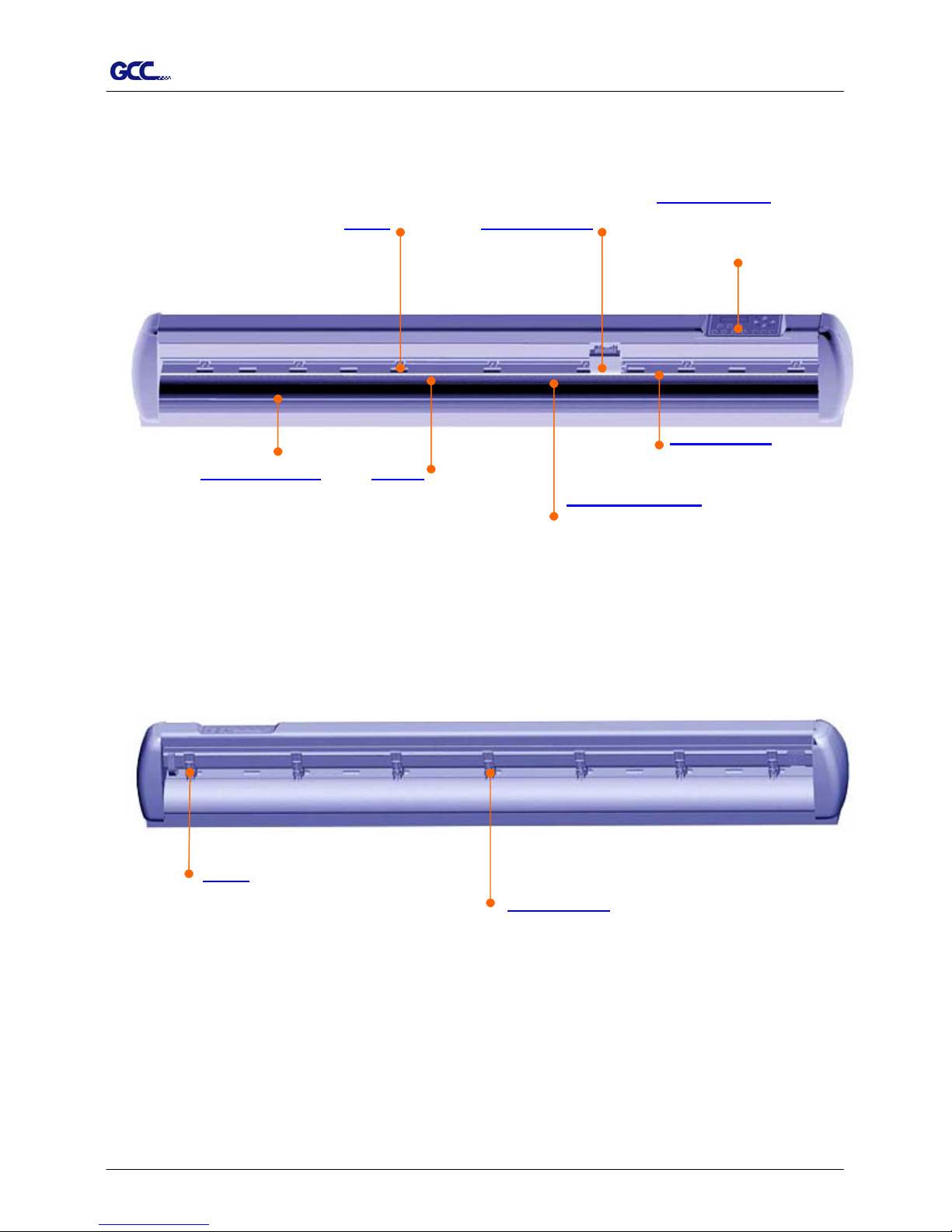
1.1.2 Front View of TP-183P
Control Panel
1.1.3 Back View of TP-183P
【Figure 1-1】
【Figure 1-2】
Pinch Roller
to hold media in the
process of plotting.
。
Lever
to raise up or lower down
the pinch rollers.
Plotting Pad
to protect the pen in the
process of plotting.
consists of 14 control keys, 1
LED, and 1 LCM to
show
messages and menus.
Drum Tool Carriage
to perform plotting with
the installed pen.
Alignment Ruler
To help align media with the
clear guideline marks
to help moving media
back and forth during
Slither Groove
to help cut off media
easily along the groove.
Platen
to support media in the
process of plotting.
Page 6

TP-183P User Manual
General Information 1-3
1.1.4 Left-Hand Side of TP-183P
【Figure 1-3】
1.1.5 Right-Hand Side of TP-183P
Parallel Interface Connector
to connect the plotter and a computer through
a
p
arallel interface cable.
Serial Interface Connector (RS232C)
to connect the plotter and a computer through
a serial interface cable.
USB Connector
to connect the plotter and a computer through
an USB cable.
AC Power Connector
to insert the AC power cord.
Main Power Switch
On when switches to [I]; Off to [O].
Fuse
3 Amp.
【Figure 1-4】
Power Switch of Take-up System
On when switches to [I]; Off to [O].
Page 7

TP-183P User Manual
General Information 1-4
1.2 Safety Precaution
Make sure the power switch is off before install the plotter.
Handle the plotter carefully to prevent damages.
Choose a proper place where meets the following conditions to set up the plotter
z The machine can be approached easily from any direction.
z Keep enough space for the plotter, accessories and supplies.
z Keep the working area stable and avoid vibration.
z Keep the temperature between 15 and 30 (
℃
60-86oF) in the workshop.
z Keep the relative humidity between 25% and 75% in the workshop.
z Protect the machine from dust and strong air current.
z Prevent the machine from direct sunlight or extremely bright lighting.
Connect the Power Supply Carefully
z Check the plug of the power cord to see if it mates with the wall outlet. If not,
consult your dealer for further assistance.
z Insert the plug (male) into a grounded power outlet.
z Insert the other end (female) of power cord into the AC connector of the cutting
plotter.
Make sure the power cord of the plotter is connected to a power outlet that is properly
grounded to earth to avoid exposing the plotter from the risk of electric shock.
The plotter must be only operated with a dedicated power outlet without any
branch-circuit power source.
Page 8
TP-183P User Manual
Installation 2-1
This chapter describes the installation procedure of Stand and Paper Take-Up System.
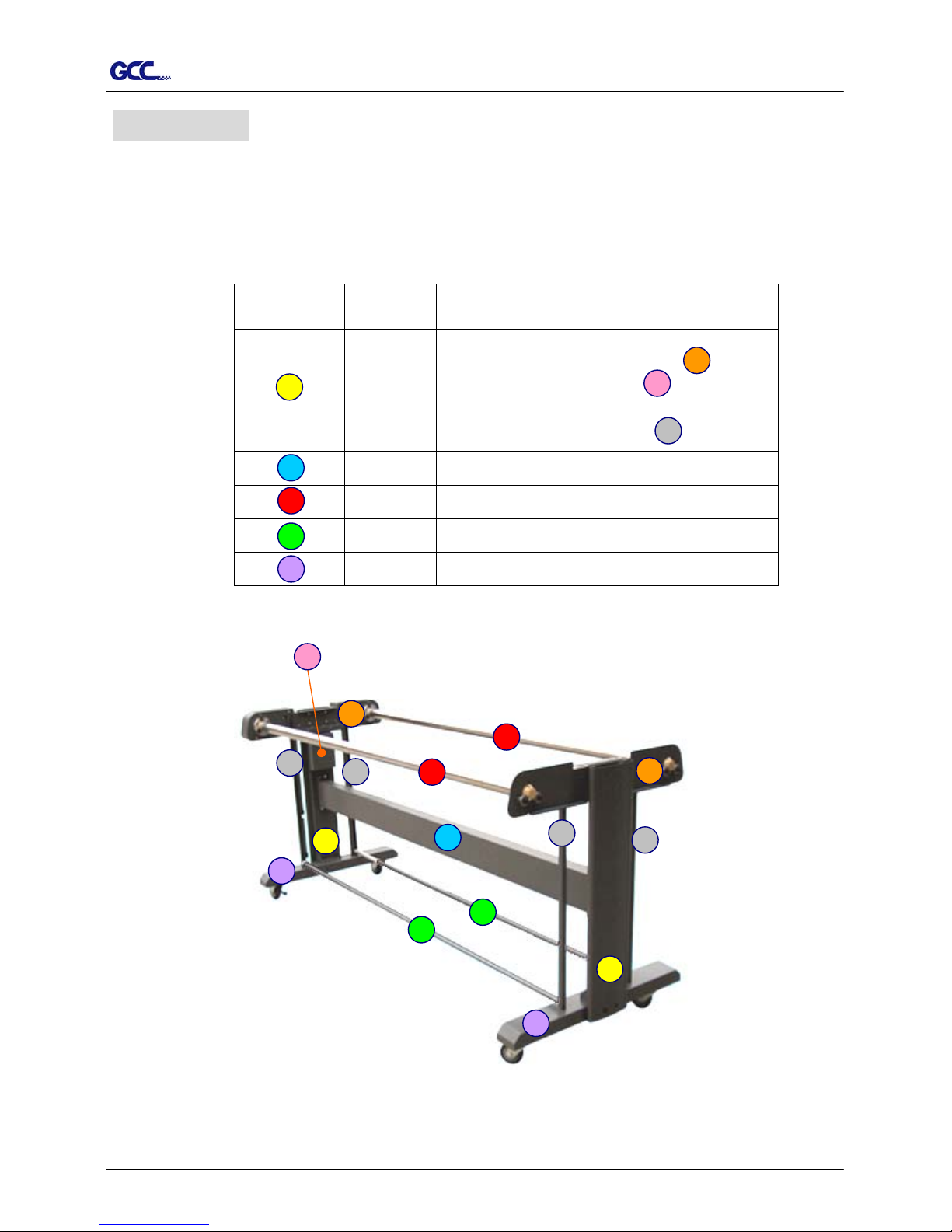
2.1 Stand Components
Component Quantity Description
2
Side Stand
Roll holder support * 2
Control board * 1
(for Paper Take-Up System)
Dancer guiders * 4
1 Stand Beam
2 Paper Take-Up & Feed Shafts
2 Dancer Bars
2 Stand Base
2. Installation
【Figure 2-1】
E
F
A
G
B
C
D
H
F
E
C
G
C
G E
G
B
G
A
H
D
D
A
H
Page 9
TP-183P User Manual
Installation 2-2
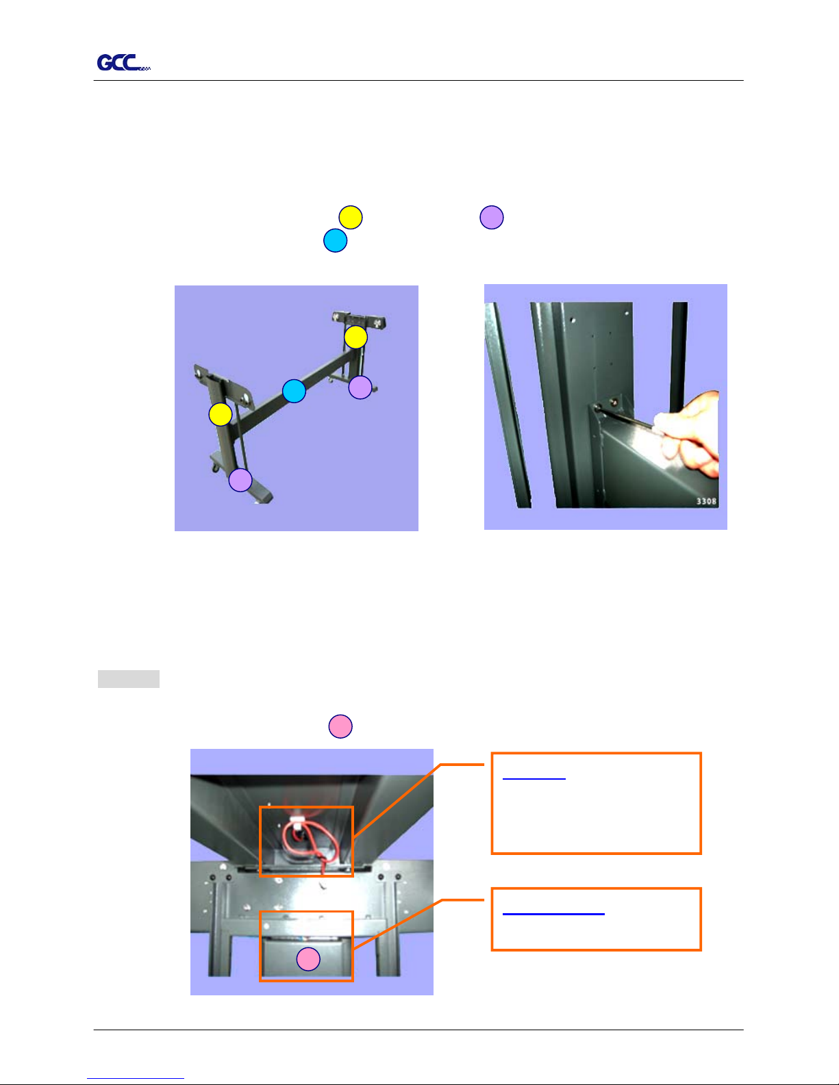
2.2 Stand Installation
It is recommended to assemble the stand by at least 2 people to prevent damages from
dropping components onto the ground.
Installation procedure:
1. Fasten 2 sets of side stand and Stand Base by supplied screws.
A H
2. Fasten with Stand Beam by supplied screws.
B
【Figure 2-3】
【Figure 2-2】
A
H
B
A
H
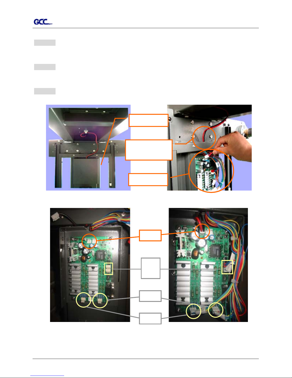
2.3 Plotter Setup
Proceed as following:
Step 1
Place the plotter onto the stand and fasten them up.
(Note: the wire and Control board must be located at the same side)
F
The wire
to connect the power board
of Paper Take-Up System
and plotte
r
Control board
for Paper Take-Up System
F
【Figure 2-4】
Page 10
TP-183P User Manual
Installation 2-3
Step 2
Take off the cover of control board.
Step 3
The wire goes through the hole showing in Figure 2-5 to reach power board.
Step 4
Plug in the head to the power connector (see the details in Figure 2-5, 2-6, 2-7 and 2-8).
【Figure 2-5】
【Figure 2-6】
The Wire goes
through the hole
Cover
Control Board
【Figure 2-7】
power
JP 6
JP 7
JP 12
【Figure 2-8】
JP 11
Page 11
TP-183P User Manual
Installation 2-4
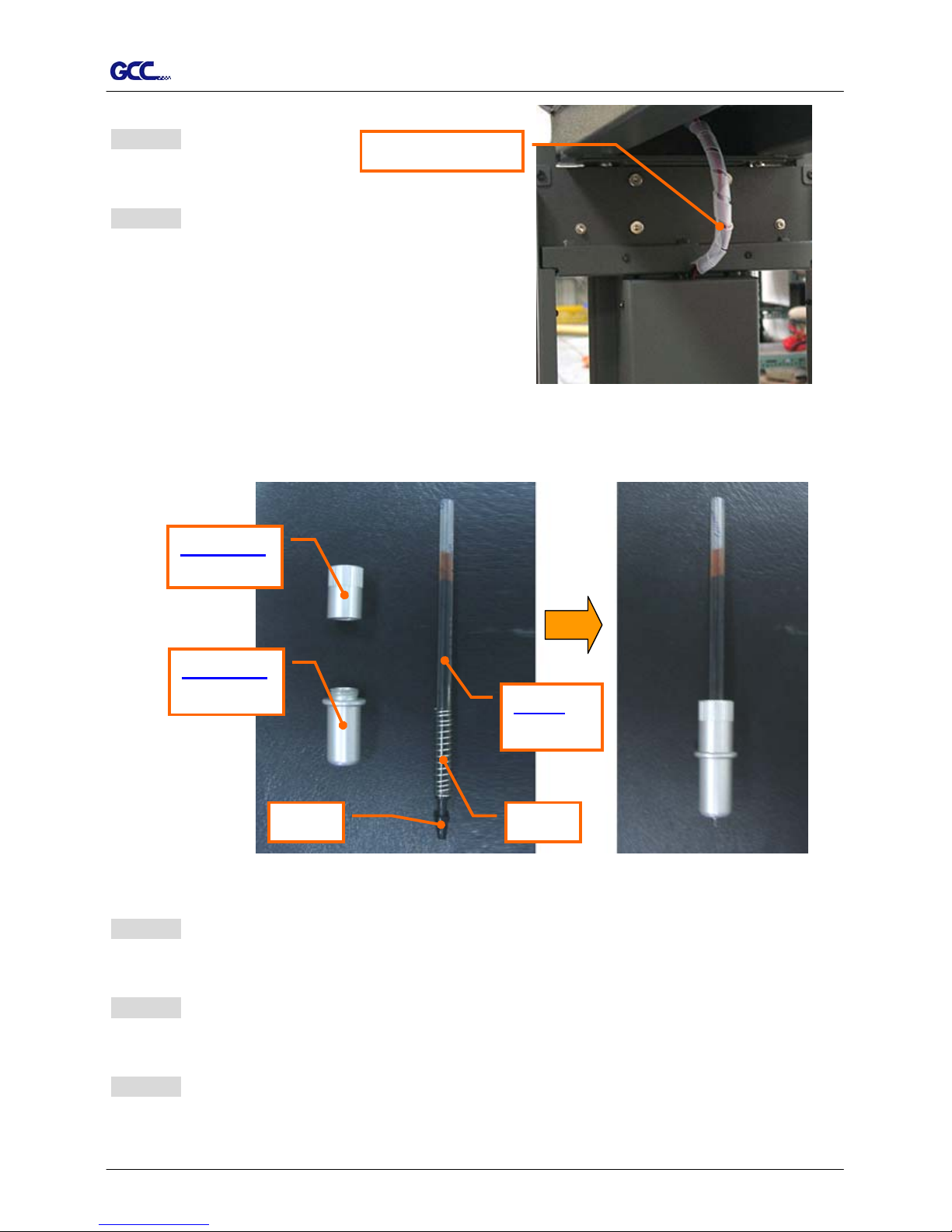
Step 5
Put the cover back.
Step 6
Wind the Corrugated Pipe around the wire for
protection from electric shock (see Figure 2-9).
Corrugated Pipe
【Figure 2-9】
2.4 Pen Installation
Penholder
Lower part
Penholder
Upper part
Cap
Refill
of ink pen
Spring
【Figure 2-11】【Figure 2-10】
Step 1
Take off the cap (Hint: put on the cap after jobs done to prolong the usage of the refill)
Step 2
Assemble the penholder, spring, and refill together (see Figure 2-10 & 2-11).
Step 3
Insert the pen holder into the carriage. The outward ring of the holder must be set onto the
grooves of the carriage firmly and locking up the grip (see Figure 2-12).
Page 12

TP-183P User Manual
Installation 2-5
【Figure 2-12】
2.4 Cable Connection
The apparel plotter communicates with a computer through a USB (Universal Serial Bus),
Parallel port (Centronics) or a Serial port (RS-232C). This section shows you how to
connect the apparel plotter to a host computer and how to set up the computer/apparel plotter
interconnection.
!! Notice: When USB connection is enabled, both parallel port and serial port will be disabled
automatically.
Parallel Port
Serial Port
USB Port
【Figure 2-13】
2.5.1 USB Interface
Vogue 183TP build-in USB interface are based on the Universal Serial Bus Specifications
Revision 1.1. (Operation system of Windows 95 and NT don’t support USB).
Page 13

TP-183P User Manual
Installation 2-6
USB driver installation
Caution!!
9 If you are using Windows 2000 / XP / Vista / 7 as your
operating system, make sure you log in using the
“Administrator” account.
Use the USB One-click Installation for quick driver installation. Follow the simple steps
below for driver setup.
Step 1:
Connecting your GCC Vogue
(1) Turn on the machine.
(2) Connect the USB connector to the machine and then USB driver will installed
automatically. It will take a few minutes to find the device. Please DO NOT
disconnect the USB cable until the installation has completed.
(3) You can double click the USB icon on the taskbar to make sure the USB device is
detected.
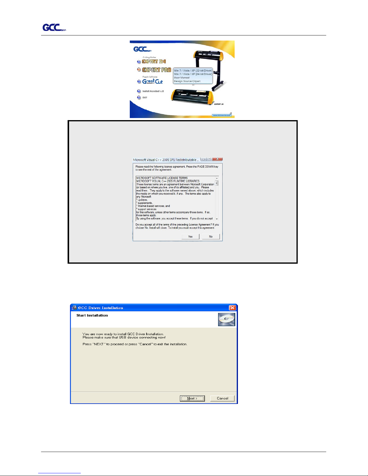
Step 2: Installing the software
(1) Put the installation CD into your CD-ROM. Please make sure that the USB device
is connected before you start the driver installation.
(2) Choose the model you want to install from the driver list and click on either the 32 bit
or 64 bit driver installation depending on the operating system installed on your
computer to start the installation. (The Expert Pro model is used as an illustration in
the following steps.)
Page 14
TP-183P User Manual
Installation 2-7
Click “Yes” to continue.
NOTE
If you use the Windows 7 / Vista 64 bit program, please note that a
pop-up window will be shown upon the initial installation as shown below:
(3) Click “Next” to start the driver installation.
Page 15

TP-183P User Manual
Installation 2-8
(4) The installation will take a few minutes to complete and you will see a message below
and click on “OK” upon completion. Enjoy your GCC Vogue!
Note:
(1) If the driver is being installed for a second time, the user will be prompted as to whether a
second copy of the driver installation is required.
(2) If the user selects yes, a second copy of the driver will be installed.
Page 16

TP-183P User Manual
Installation 2-9
2.5.2 Parallel Interface
Connecting to the Parallel Port (Centronics)
a. Connect a parallel cable to the apparel plotter and the host computer.
b. Set up the output port LPT1 or LPT2 from your software package.
c. Send data to the apparel plotter directly from your software, or use DOS commands,
like TYPE or PRINT, to output data.
2.5.3 RS-232 Interface
Connecting to the Serial Port (RS-232C)
a. For IBM PC or compatible systems, connect the RS-232C cable to the serial connector
of your host computer at the assigned port (COM1 or COM2).
b. Set up the communication parameters (Baud Rate and Data Bits/Parity) to match the
setting of your software package. Refer to chapter 3.3 – “Misc” key description for
more details.
2.5.4 Data Transmitting
There are two options to transmit the data from the computer to the apparel plotter:
Option 1
With proper interface settings, the data can be transmitted from your application software
package to the apparel plotters directly.
Option 2
Most patterning software packages are able to emulate HP-GL or HP-GL/2 commands,
therefore. As long as the file is HP-GL or HP-GL/2 format, the apparel plotter can output the
data precisely.
Page 17

TP-183P User Manual
The Control Panel 3-1
3. The Control Panel
This chapter describes the button operations with the LCM menu flowcharts. When the apparel
plotter is ready for use as described in Chapter 1 & 2, all functions are under default parameters.
3.1 The LCD Panel
SPEED FORCE OFFSET
MISC TOOL SELECT DATA CLEAR CUT TEST
ON/OFF
LINE
PAUSE / RESUME ENTER
POWER
< LCD Control Panel on Vogue TP-183P>
Key Function
LCD Screen To display functions and error messages.
Power LED To indicate the power status ( light up: power on; light off: power off )
4 Arrow Keys To move position, select function, or change setting.
ENTER To set item or register the immediately preceding input value.
PAUSE/RESUME To temporarily halt plotting process or to continue.
ON/OFF LINE To switch modes, stop plotting job, or abort changes of settings.
OFFSET ( Non-functional at this model )
FORCE To adjust the value of plotting force.
SPEED To adjust the value of plotting speed and quality.
CUT TEST To perform plotting tests.
DATA CLEAR To clear up buffer memory.
TOOL SELECT To select tools.
MISC To set up functions.
Page 18

TP-183P User Manual
The Control Panel 3-2
3.2 Menu in On-line Mode
Power On
Firmw a re V -.-Copyright 2003
Place Media And Then
Lower Dow n The L ever
Sizing Media Width
Lever Up to Abort
Siziing Media Length
Lever Up to Abort
S---.- F ---.- O -.-- M
L:-----.-- W : ----.--
Top menu
D a ta In P ro c e s s in g
Sending data
Pause
Setup Resume
[PAUSE]
Force: 55 gf
OK : E NT E R
[Force key]
Vogue TP-183P in processing
Us e to s e lec t;
[EN T ER ] to enable the setting
Non-Functional
At This Model
Clear data memory
N: Cancel OK: ENTER
1S:72 F:80 O: 0.275 M
Se lec t O K : EN T E R
[Offs e t ke y ]
[Data Clear]
[Tool Select]
Speed: 108cm/s
Se lec t: O K : EN T E R
[Speed Key]
Up Speed: 108cm/s
Se lec t: O K : EN T E R
Qu a lity: N o rma l
Se lec t: O K : EN T E R
Sm oothing Plot
Se lec t: O K : E n te r
Panel Setup
Se lec t: O K : En ter
Restore default
Se lec t: O K : E n te r
Save parameter
Se lec t: O K : E n te r
Vogue TP-183P
LCM Version 1.0
Set Pen's Lifespan
Se lec t: O K : En ter
Page 19

TP-183P User Manual
The Control Panel 3-3
3.3 Menu in Off-line Mode
Press [ON/OFF LINE] to switch online and offline mode
Please [Enter] to finish setup of each function.
Offline For
System Setup
[Force Key]
[OFFSET KEY]
[Data Clear ]
[ ]
[Speed Key]
[Cut Test]
[Tool Select]
[Misc]
Force: 55 gf
OK: Enter
Non-Fubctional At This
Model
Clear Data Memory
N: Cancel OK: Enter
Move Origin
X: Y:
Speed: 108cm/s
Select: OK: Enter
Up Speed: 108cm/s
Select: OK: Enter
Quality: Normal
Select: OK: Enter
Square Plot
Select: OK: Enter
Repeat Last Plot
Select: OK: Enter
Media Back & Forth
Select: OK: Enter
Set Communication
Select: OK: Enter
Select Units
Select: OK: Enter
Scale Length
Select: OK:Enter
Scale Width
Select: OK: Enter
Smoothing Plot
Select: OK: Enter
Panel Setup
Select: OK: Enter
Speed: 3-153cm/s with an increment of 3cm/s
Upspeed: 3-153cm/s with an increment of 3cm/s
Draft, Fair, Normal, Fine, Small Letter
0-55gram with an increment of 5 gf
Metric (cm/ gf) or
English measurement(feet/ounce)
Firmware: x.x.xx
FPGA: Vx.x
Restore default
Select: OK: Enter
Save parameter
Select: OK: Enter
Set Pen's Lifespan
Select: OK: Enter
Replot # 1
Select: OK: Enter
Copy # 1
Select: OK: Enter
USB Printer Type
Select: OK:Enter
GCC USB Mode
Common USB Mode
Page 20

TP-183P User Manual
The Control Panel 3-4
3.4 Description of Menu Items
Below describes the functions of menu items:
Menu or Key Function Setting Default
--- POWER ---
to indicate the power status.
[ Arrow Keys ]
1. to move the tool carriage position on X or Y axis.
2. to select functions or change values of the setting.
[ ENTER ]
1. to effect the displayed parameters that will be saved
automatically.
2. to set a new origin at the present tool carriage position.
In “offline” mode, moving the tool carriage to desired
position by [Arrow Keys], then press [ENTER] key to set
a new origin. While moving with the parameters of
XY-axes displayed, press [MISC] key will enable
fine-tune movement; press [MISC] key again to disable
the function.
[ PAUSE/RESUME ]
to temporarily halt the plotting process; to resume the
process by press [Pause/Resume] key again.
[ ONLINE/OFFLINE ]
1. to switch between online mode and offline mode.
2. to stop the plotting job or abort the change of setting.
Once press this key, the plotting job will be terminated
immediately and cannot be resumed.
[ OFFSET ]
non-functional at this model
[ FORCE ]
to set or modify the value of tool force. 0~55gram;
5 gram/per step
55 gram
[ SPEED ]
Speed to set or modify tool speed at horizontal moving. 3~153cm/sec;
3cm/sec per
step
108cm/sec
Up Speed to set or modify tool speed at vertical moving. 3~153cm/sec;
3cm/sec per
step
108cm/sec
Quality to set or modify plotting quality.
While cutting small letter, set as “Small letter”;
while cutting in high speed, set as “Draft”;
for normal operation, set as “Normal”.
Draft, Fair,
Normal, Fine,
Small Letter
Normal
[ CUT TEST ]
Square Plot to perform a plotting test at present blade position.
for more information, please refer to page 2-7 to adjust
blade force and cutting speed.
Repeat Last
Plot
Replot
to repeat the last job without re-sending the data.
1~99;
1 per step
Page 21

TP-183P User Manual
The Control Panel 3-5
Copy:
to copy the last job without re-sending the data.
* 1mm gap will be auto-generated between 2 copies).
* if the media length is not enough to continue, it will show
below message on LCM:.
OpOtuSfa;ce #
iCfopoe isfn his ed
* if both functions are enabled at the same time, the cutter
will
perform the last setting only.
1~99;
1 per step
[ DATA CLEAR ]
to clear up data memory.
[ TOOL SELECT ]
Save
Parameter
to save plotting parameters for later use. Patterns1~4 Pattern 1
Accept setup command:
to accept commands of the Force, Speed, and Cutting
Quality only via software.
Panel Setup
Control panel only:
to accept commands of the Force, Speed, and Cutting
Quality only via control panel of the plotter.
Smoothing
Plot
to enable smooth-cutting function. Enable
Set Pen’s
Lifespan
To customize the length of Pen’s lifespan. Unit: M
Restore
default
to turn all parameters of the menu items to factory-default
settings.
[ MISC ]
Media Back
& Forth
to enable to save time on repeated plotting jobs and better
tracking.
After plotting job has finished, the media will move back to
the origin, then move to the end of the plot.
Disable
Set
Communication
to build up the communication between host computer and
plotter.
Baud Rate is to determine the speed of data transmission.
Data Bits refers to the size of one block of data.
Parity is used to check if data was revived correctly or not.
9600, n, 8, 1, p 9600pbs, 8 Bits with NO Parity
19200, n, 8, 1, p 19200pbs, 8 Bits with NO Parity
Firmware
Version
to display the version number of Firmware and FPGA
code.
Select Units Provides two unit systems for users convenient. cm/gram;
inch/oz
Metric
Page 22

TP-183P User Manual
The Control Panel 3-6
Scale Length
Scale Width
to adjust the scale of media length and width that may
cause by the thickness of the media.
The Denominator is the actual length, and the Numerator
is the ideal length measured from the resultant.
For example, cutting a line with 500.0 mm length. The
procedure as followng:
1. Press the [LEFT ARROW] to choose the Numerator and
select 500.0 mm,
2. Plot the length by sending a graph file,
3. Measure the length then use the [RIGHT ARROW] key
to choose the Denominator, then
4. Press [UP ARROW /DOWN ARROW] to change the
values of the actual length.
USB Printer
Type
To select USB Mode from the LCM panel. Two USB modes
are available: GCC USB Mode and Common USB Mode.
GCC USB Mode: For 32 bit driver
[Windows XP/2000/ 7 /Vista]
Common USB Mode: Both for 32 bit & 64 bit driver
[Windows XP/7/Vista]
Common
USB Mode
Page 23

TP-183P User Manual
Operation 4-1
4. Operation
4.1 Paper Loading
Step 1
Install one paper hub onto one side of paper roll.
Step 2
Slide the feed shaft through the paper roll.
Step 3
Install the other paper hub onto the other end of
Paper Roll
Paper Hub
Feed Shaft
paper roll and set it firmly/ (Figure 4.1).
【Figure 4-1】
Step 4
Install the shaft with Paper Roll onto the rear side of Roll Holder Support.
( to ; to : Figure 4-2 & 4-3).
C1
E 1
C2
E 2
Step 5
Draw out paper from upper side of the paper roll, then go through the plotter to the front side.
Make sure paper is loaded on center of the platen before press down Lever (Pinch Roller) .
(Figure 4-4 & 4-5)
【Figure 4-2】
【Figure 4-3】
Slot
C1
E 1
C2
E 2
Page 24

TP-183P User Manual
Operation
4-2
Step 6
Fix paper on the front shaft by twin adhesive tape (Figure 4-6).
Step 7
Place the two dancer bars into the dancer guiders . (Figure 4-7)
(Detailed composition refer to Figure 2-1)
Step 8
Adjust the two dancer bars to the position between
sensors by loose or tighten the paper roll.
(Figure 4-8)
【Figure 4-8】
Sensor
Dancer bar
【Figure 4-7】
GD
【Figure 4-5】
Draw out paper from upper
side of the roll.
【Figure 4-4】
【Figure 4-6】
Page 25

TP-183P User Manual
Operation 4-3
4.2 Adjust the Plotter
For loading media properly, follow below procedures to adjust the plotter:
Step 1
Use the lever on the upper right side of the plotter to raise or lower down pinch rollers. Pull the
lever forward until it makes a clicking sound then the pinch rollers are raised (Figure 4-9).
Lever
【Figure 4-9】
Step 2
Load your media on the platen and slide it under the pinch rollers from either the front side or
the backside. The color alignment rulers on the platen extension will help you to adjust the
media precisely.
Step 3
Move the pinch rollers manually to proper positions. Be sure the pinch rollers must be
positioned above the grid drum. The white marks on the main beam reveal where the grid
drums are located (Figure 4-10).
White marks
【Figure 4-10】
【Figure 4-11】
Note:
Always adjust the position with the pinch roller raised.
Move the pinch roller by applying force at the rear portion of the pinch roller support.
Do not move the pinch roller by holding its front rubber roller (Figure 4-11).
Page 26

TP-183P User Manual
Operation 4-4
Step 4
Push the lever backward to lower down the pinch rollers.
Step 5
Turn on the power. The tool carriage will measure the media size automatically.
4.3 Tracking Performance
In order to achieve the best tracking performance for a long plot, it’s recommended to
follow up below regulations:
If the media length is less than 4 m, leave the margin of 0.5mm ~ 25mm in the left and
right edges of the media (Figure 4-12).
Pinch roller
Pinch roller
0.5mm - 25mm
0.5mm - 25mm
【Figure 4-12】
If the media length is over 4m, leave at least 25mm margin on the left and right edges
of the media (Figure 4-13).
>25mm > 25mm
【Figure 4-13】
Page 27

TP-183P User Manual
Operation 4-5
4.4 Adjusting the Plotting Force
Before sending your designs for plotting, you may perform a “cut test” to generate
satisfactory plotting results.
“Cut Test” should be repeated until the appropriate plotting conditions for the media are
discovered.
After sizing the media, press [CUT TEST] button to select the “square cut”, and press
[ENTER KEY] to confirm.
The default pen force of the cutting test is 55gf. Press [ARROW KEY] to move the tool
carriage to the position where you like. Then, press the [ENTER KEY] to perform Cut
Test.
Note: At the same time, the new origin is also set at the cutting test position.
Page 28

TP-183P User Manual
Basic Maintenance 5-1
This chapter explains the basic maintenance required for the apparel plotter. All the other
maintenance without mention here must be performed by a qualified service technician.
5.1 Cleaning the Apparel Plotter
In order to keep the apparel plotter under good condition and best performance, it’s
Recommended to clean up the machine properly and regularly.
CAUTION !
Gently wipe the apparel plotter surface with a lint-free cloth. If necessary, clean with a damp
cloth or an alcohol-immersed cloth. Wipe with water to rinse off any residue and dry with a
soft, lint-free cloth.
Wipe all dust and dirt from the tool carriage rails.
Use a vacuum cleaner to empty any accumulated dirt and media residue beneath the pinch
roller housing.
Clean the platen and pinch rollers with a damp cloth or an alcohol-immersed cloth, then dry
with a soft, lint-free cloth.
Wipe dust and dirt from the stand.
5.2 Cleaning the Grid Drum
Step 1
Turn off the apparel plotter, and move the tool carriage
away from the area needed to be cleaned.
Step 2
Raise the pinch rollers and move them away from the grid drum for cleaning.
Step 3
Use a bristle brush (toothbrush is acceptable) to remove dust from the drum surface. Rotate the
drum manually while cleaning (Figure 5-1).
Unplug the apparel plotter before cleaning
to prevent electrical shock.
Never use solvents, abrasive cleaners or
strong detergents for cleaning. They may
damage the surface of the apparel plotter
and the moving parts.
5. Maintenance
【Figure 5-1】
Page 29

TP-183P User Manual
Basic Maintenance 5-2
5.3 Cleaning the Pinch Rollers
If the pinch rollers need a thorough cleaning, use a lint-free cloth or cotton swab to wipe
away the accumulated dust from the rubber portion of the pinch rollers. To prevent the
pinch rollers from rotating while cleaning, use finger to hold the pinch rollers not to rotate.
If need to remove the embedded or persistent dust, use the lint-free cloth or cotton swab
moistened with rubbing alcohol.
5.4 Cleaning the DU-typed and A-typed rollers on carriage
Step 1
Turn off the apparel plotter.
Step 2
Disassemble the top cover and the cover of carriage.
Step 3
Use a bristle brush (toothbrush is acceptable) to remove dust on the roller surfaces, meanwhile
move the carriage slowly along the rails (Figure 5-2 & 5-3).
5.5 Cleaning the Motors
Step 1
Turn off the apparel plotter.
【Figure 5-2】
DU-typed Roller
【Figure 5-3】
A-typed Roller
Page 30

TP-183P User Manual
Basic Maintenance 5-3
Step 2
Disassemble the top and side covers.
Step 3
Use a bristle brush (toothbrush is acceptable) to remove dust around the X-axis and Y-axis
motors (Figure 5-4 & 5-5).
5.6 Cleaning the PC boards
Step 1
Turn off the apparel plotter.
Step 2
Disassemble the front and rear platens.
Step 3
Use air gun or blower(cold air) to remove dust on the PCB surface.
【Figure 5-4】 【Figure 5-5】
Page 31
TP-183P User Manual
Troubleshooting 6-1
6. Trouble Shooting
This chapter helps you to correct some common problems that may come across. Prior to
getting into the details of this chapter, please be sure that your application environment is
compatible with the apparel plotter.
Note:
Before having your apparel plotter serviced, please make certain that the malfunction
is in your apparel plotter, not the result of an interface problem or a malfunction in your
computer or a software problem.
Why is the apparel plotter not functioning?
Possible Causes:
6.1 Non-Operational Problems
Check the following first:
Does the AC power cord plug in properly?
Does the AC power cord connected to the power connector properly?
Does the power LED still illuminate?
Solutions:
If the LCM is able to display the message, the apparel plotter should be in a normal
condition. Switch off the apparel plotter and turn it on again to see if the problem’s still
existing.
If the LCM is unable to display any message, contact the technician from your dealer.
Page 32

TP-183P User Manual
Troubleshooting 6-2
6.2 Operational Problems
Some mechanical problems or failure during operation will cause some problems. The error
messages shown on the LCM present the problem first, and followed by recommended actions.
If the problem still exists after the recommended actions have been done, have your apparel
plotter serviced.
Error, Check Media
Or Drum or X Motor
This message indicates that there might be a
problem on the X axis. Check if the drum is
working well and if the media is well loaded.
Correct the problem and re-power on to reboot
system.
Error, Check Media
Or Y Motor
This message indicates that there might be an
obstruction to carriage relating to a problem on
the Y axis. Correct the problem and re-power on
to reboot system.
Error, Check Carriage
Sensor or VC Motor
This message indicates that the blade up/down
sensor malfunction. Re-power on to re-boot
system. If the problem still exists, find a
serviceman.
Graph Was Clipped.
Data In Buffer
This message indicates that the apparel exceeds
the apparel limit. Reload larger media or re-scale
the plot to a smaller size; then press the key
followed by the display of LCM to continue.
Page 33

TP-183P User Manual
Troubleshooting 6-3
6.3 Data Communication Problems
The messages showed below present problems in relation to apparel plotter/computer
communication.
Communication Error
Setup: MISC. key
Is the connection cable connected
to the apparel plotter and computer
properly?
Yes No
Has the interface setting been
done correctly?
Refer to Chapter 4 Connecting your apparel
plotter.
Yes No
Refer to the “MISC” key in
Chapter 3 - Description of
Operation for the port setup.
Try the communication
between your apparel plotter
and computer. If it still does
not work, have your apparel
plotter serviced.
Note:
The computer also needs to set up compatible communication parameters to the
apparel plotter set up.
If your apparel plotter can not recognize the
HP-GL/2 or HP-GL commands, please check
the HP-GL/2 or HP-GL commands applied to
your apparel plotter are used properly.
HP-GL/2 Cmd. Error
Page 34

TP-183P User Manual
Troubleshooting 6-4
6.4 Software Problems
Check the following first:
Does your software support HP-GL and HP-GL/2 drivers?
(* check the configuration settings of your software.)
Yes
No
Does your software package indicate that it will work with your
computer and apparel plotter?
Does the apparel plotter interface
match the requirements of your
software?
Does your
software
recommend using
a different cable?
Yes No
Most well-known patterning software
in the world has drivers for our
apparel plotters. If your software
doesn’t support TP-183P driver, use
software that has HP-GL and
HP-GL/2 emulation supports and you
can chose the following three drivers:
z A3 size: HP7475A
z A1 size: HP7580A
z A0 size: HP Draf Pro Exl or HP
Yes
No
Refer to Chapter 4,
connecting your
apparel plotter.
No
Does the software
vendor provide a
sample file?
Yes
Try using the
recommended
cable.
Re-power on the
apparel plotter and
try to send the file
again.
Do something about the
error message display on
LCM, or consult your
software vendor.
Page 35

TP-183P User Manual
Troubleshooting 6-5
6.5 Plotting Quality Problems
Is the pen installed correctly and the pen holder
fastened securely?
No
Yes
Refer to Chapter 2-4
“Pen Installation”.
Is the pen dull or
chipped?
Yes No
Replace
with a new
pen
Is tool force set up
properly? (The default
for tool force is 55 gf)
Yes No
Is the tool offset set up
properly?
Adjust the tool force to obtain
an optimum pen force. Refer to
chapter 4-4 “Adjusting the
plotting force”.
Yes No
Is there any dirt adhered to the
pen?
Adjust the tool offset to
obtain an optimum value.
Yes
No
Remove the pen
and clean it.
Please contact your dealer for technician
support.
Page 36

TP-183P User Manual
Vogue Specification A-1
Vogue Specification
Model Name Vogue TP-183P
Max. Media Loading Width 1900mm(74.8”)
Min. Media Loading Width 900mm(35.4”)
Max. Plotting width 1830mm(72”)
Number of Pinch Rollers 7
Max. Plotting Speed Up to 1080mm/sec (42.5 ips)
Motor DC Servo Control
Acceptable Pens Disposable Ink and Ball Point Pens
Max. Plotting Length at one job 20m(65.6’)
Max. Roll-Media Weight 40kg
Acceptable Media (g/m²) 40g ~ 80g
Max. Roll Media Diameter 200mm(7.87”)
Roll Media Core Diameter 50mm or 76mm (2” or 3”)
Hardware Interfaces USB, Parallel, RS-232
Data Buffer 4MB
Commands HP-GL, HP-GL/2
Stand and Take-up System Yes
Net Weight 105kg
Dimension(W*L*H) 750*2170*1160mm (29.5”*85.4”*45.7”)
y Compatible with Windows 2000/XP/7.
y The specification and data sheet may vary with different materials used. In order to obtain
the best output quality, please maintain the machine regularly and properly.
y GCC reserves the right to change the specifications at any time without notice.
Page 37

TP-183P User Manual
Vogue CAD Output Accessory Instruction A-2
1
Vogue CAD Output Accessory Instruction
Chapter 1 Vogue CAD Output Accessory(GCC plotter software、Dongle)Instruction….2
Chapter 2 The setting of GCC Plotter output………………………………………………… …….4
Chapter 3 Automatic queuing function………………………………………… ……………………8
Page 38

TP-183P User Manual
Vogue CAD Output Accessory Instruction A-2
2
Chapter 1 Vogue CAD Output Accessory(software、dongle)Instruction
1、 If you have installed previous versions of the GCC plotter software, please remove it from the control
panel in your PC.
2、 Insert the installation CD and click “setup.exe”.
3、 Click “OK” to continue with the installation.
4、 Click on the button shown below to install GCC plotter software.
5、 Click “Yes” to continue with the installation.
6、 Click on the button shown below to copy the files from the installatio n CD to your PC. You do not need to
restart your PC.
Page 39

TP-183P User Manual
Vogue CAD Output Accessory Instruction A-2
3
7、 Plug-in the dongle and start the GCC plotter software. You will see the window below showing that the
installation has been completed correctly.
Page 40

TP-183P User Manual
Vogue CAD Output Accessory Instruction A-2
4
Chapter 2 The setting of GCC Plotter output
1、 Install the Vogue driver.
Install the Vogue driver and set up the ports as USB. (See Chapter 5 for details.)
Please note that if you output through the printer port, you need to set up the port to LPT port; if you
output by RS-232, you have to set up the port to the COM port.
2、 Please note that you must set the GCC plotter as the default printer.
3、 Click
to set up the parameter as below and then click “save”. (The resolution should be set to 1016
lpi)
Note:There are three different resolutions for different plotting ratio
0.025 correspond to 1016 lpi(Most markers use this plotting ratio);
0.0254 corresponds to 1000 lpi; (commonly used by Gerber software);
0.01 corresponds to 2540 lpi.
The setting of length: the length of the output paper
The setting of width: the width of the output paper
Note 1:The value of length cannot be over 60cm.
Page 41

TP-183P User Manual
Vogue CAD Output Accessory Instruction A-2
5
Note 2:Enter the length and width of the media in the corresponding fields.
4、 Click
and choose to import the file (PLT format) you want to plot.
Note: you can import the PLT file with different resolutions.
5、 Preview the file.
The length(X) and width(Y) of the image File name and path
Coordinates
Ratio
7. Adjust the ratio
Click “Tools” → “Regulation” to set up a ratio for each textile marker (for e.g. 0.2, 0.5, 1.2 etc) and press
“OK”.
Page 42

TP-183P User Manual
Vogue CAD Output Accessory Instruction A-2
6
Note: The coordinates must be a positive number or the output image might not be outputted completely.
You can move the coordinates manually to ensure that the coordinates are positive and thus will be
outputted correctly.
6、 Click the
icon to access the window below:
The following options are available:
1) Click
to modify the length and the width of the media.
Enter the length and the width of the media and press “Enter”.
2) Click
to set up the distance of each textile marker.
Enter the distance of each textile marker and press “Enter”.
Page 43

TP-183P User Manual
Vogue CAD Output Accessory Instruction A-2
7
3) Click to indicate the starting segment of the textile marker or continue with the last
plotting job.
4)Click
to output the file with a 1:1 ratio
Enter the number of copies and press the Enter key to output the file.
Page 44

TP-183P User Manual
Vogue CAD Output Accessory Instruction A-2
8
Chapter 3 Automatic queuing function
1、 Click Open Pool and keep GCC plotter software in the online status
2、 Copy the PLT file to C:\GCC\Spool (Assuming that the GCC plotter software has been installed in C:\ )
The files in the spool will be output automatically by the automatic queuing function. Note that the PLT
file will be deleted after the completion of each job.
 Loading...