

Page 1
User Manual
Great Computer Corporation ©
V2 2003/7/3
Page 2
Jaguar II User Manual
Important Information I
Thank you for purchasing the SignPal Series – Jaguar
ⅡⅡⅡⅡ
.
Before you use the cutting plotter, please make sure that you have read the safety
precautions and Instructions below.
Caution
!
SAFETY PRECAUTIONS!
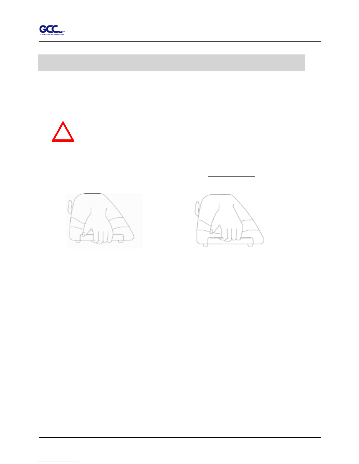
! For safety concern, please always hold the cutter firmly from the bottom when moving it. Do
not move the cutter by clasping the depression area on both sides.
# Do not shake or drop the blade holder, blade tip can fly out.
# During operation, do not touch any of the moving parts of this machine (such as the carriage).
Also be careful that clothing and hair do not become caught.
# Always connect the power cable to a grounded outlet.
# Always use the accessory power cable that is provided. Do not wire the power cable so that it
becomes bent or caught between objects.
# Do not connect the power cable to branching outlet to which other machines are also connected, or
use an extension cable. There is danger of overheating and of mis-operation of the machine.
# Keep the tools away from children where they can reach.
# Always put the pinch rollers within the white marks.
Important Information
O (correct)
X (Incorrect)
Page 3
Jaguar II User Manual
Important Information II
HOW TO CUT 3mm LETTERS ?
# To obtain good quality output, narrow width media is suggested. However, if wide media is used,
you should:
1. Position two pinch rollers as close as possible to both edges of the cutting area.
2. Make sure the loaded media is held flat with equal tension across the platen.
3. Suggested operation settings:
Tool force: 55 gf. (or depending on the material)
Cutting speed: 45-50 cm/sec
Tool up speed: 45-60 cm/sec
Smooth cut: DisableCutting
Quality: Small Letter
HOW TO MAKE A LONG PLOT ?
# When you are making a long plot with a roll of heavy and wide vinyl paper you need to use
AUTO UNROLL MEDIA function ( see page 41 ) :
1. If the length of graphic is between 3m and 5m, the cutting speed is better
slower than 45cm/sec and the cutting quality is set as Normal.
2. If the length is longer than 5 m, the CUTTING SPEED is better slower than
30 cm/sec.
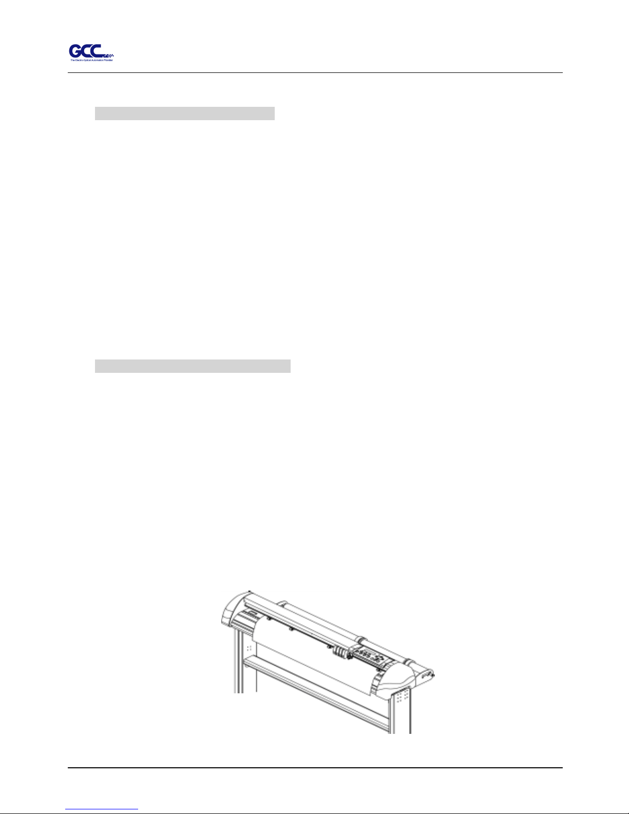
3. After loading the roll media all pinch rollers are raised at this stage, flatten
the media on the platen and hold the front edge of the roll media firmly. (See
Figure 0-1)
Figure 0-1
Page 4
Jaguar II User Manual
Important Information III
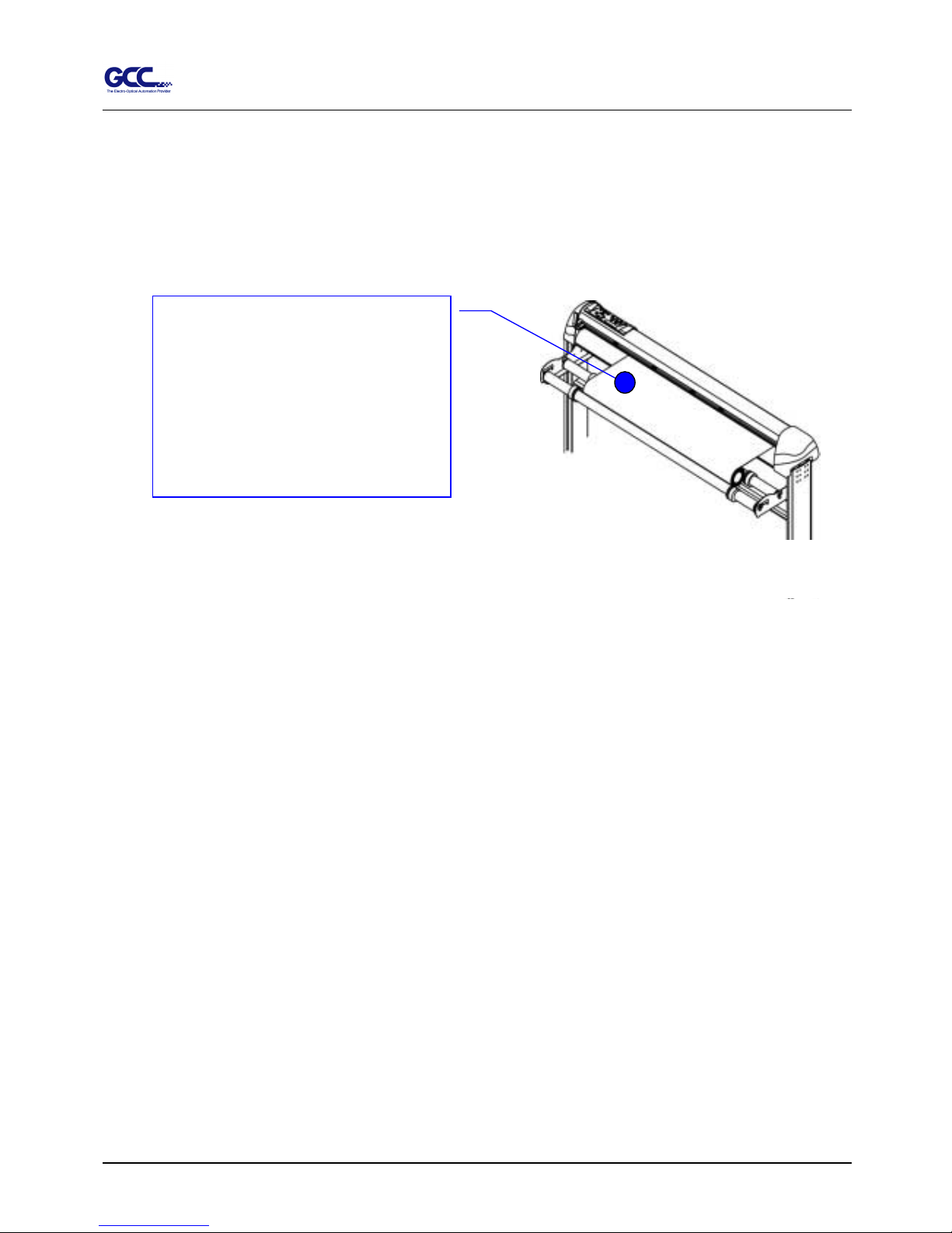
Then turn the roll downward to make an equal tension across the media
(See
Figure 0-2
)
4. Engage pinch rollers.
5. Fixes roll media guide bushes on the roll holder to secure the roll media.
6. The protrusion length of the blade should be longer than the thickness of the vinyl.
(Please see in the section of “ABOUT THE TOOL”.) After you notice all above then
you’ll enjoy your gigantic signs production!
♪ Make sure that the media
tension is equally distributed
from left to right. If the media
were not tighten enough against
the platen, it would cause
tracking problems.
Figure 0-2
Page 5
Jaguar II User Manual
Important Information IV
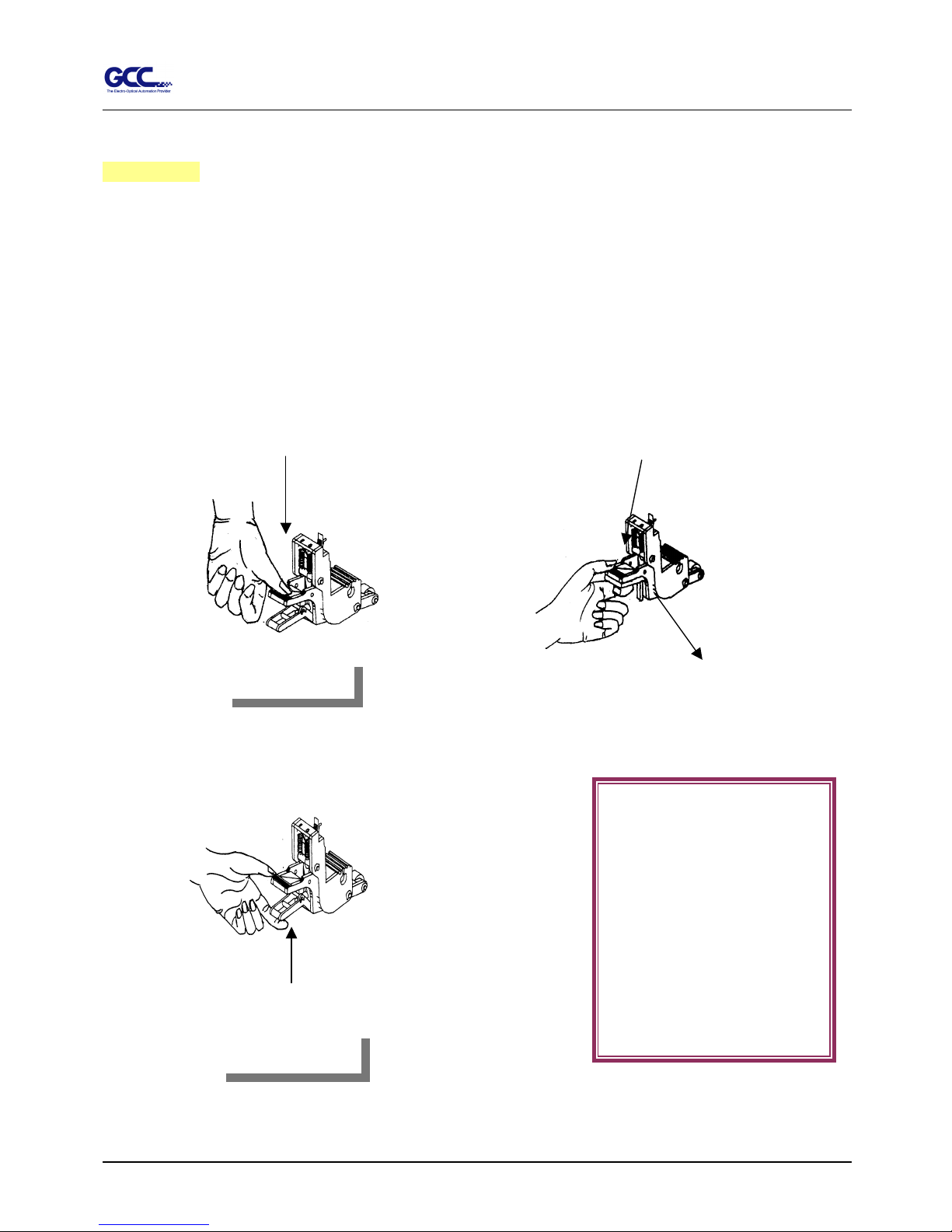
Warning
Never press the top release grip and pull the bottom release grip at the same time as the pictures
shown below:
○
○○
○ (CORRECT)
╳
╳╳
╳ (INCORRECT)
Press down
DISABLE
ENABLE
Pull up bottom release
Press down
Stop
Note:
In case the grips clipped
together due to your wrong
operation, please use a
tweezers to pull out the stop
bar when pressing down the
top release grip. Keep the
stop bar outside then release
Figure 0-3
Page 6

Jaguar II User Manual
Quick Menu
Quick Menu V
1. Power ON. (LED lights on)
2. Place the media and lower down the pinch rollers (must position above the grid drums).
3. Sizing - Press the related Arrow Keys for roll (cut from the current position), edge (cut from the
edge) or single.
4. Setup computer and connect with cutting plotter properly.
5. On-line condition - Plotter is ready to receive data from computer.
LCM shows:
Rydaeortcveeei
L-: ----.-- W: -- .--
M
--
Only under the “Ready to Receive” can press setup keys, such as CUT_TEST, SPEED_KEY,
FORCE_KEY, OFFSET_KEY, MISC.KEY, TOOL_SELECT_KEY, and also the ARROW_KEYs.
Cutting test - Press CUT TEST, position carriage by arrow keys, ENTER.
Speed/Force/Offset - Press related key to adjust then repeat the step of Cutting Test for best
cutting result.
Function – Recut, Copy, Quality, Setup and Communication Setup follow the instruction shown
on LCM.
6. As the cutting plotter receive data from host, LCM displays as follow:
DPataI
SFO
rncsoes ing
---.-- ---.-- -.---
English Unit
E
When you are at this state, the only key you can press is Pause_Key.
7. Change the setting value during cutting - Press PAUSE, for continue cutting press RESUME.
8. Data Clear - Will terminate the cutting and clear the data in the buffer. Press DATA CLEAR
then ENTER.
Meter Unit
Page 7
Jaguar II User Manual
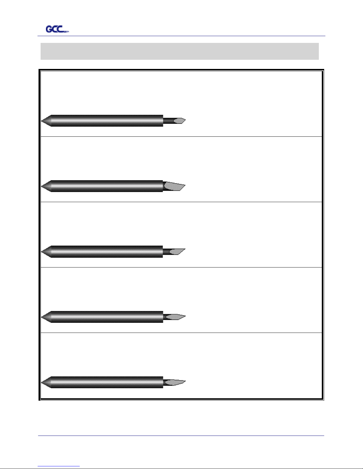
The Specification for GCC Blade VI
For cutting general signage vinyl. Blade with largest angle.
BK07026A
BK07026ABK07026A
BK07026A
GCB
GCBGCB
GCB----145S
145S145S
145S
The blade is 45°with Yellow Cap
Yellow Cap Yellow Cap
Yellow Cap, 0.25 mm blade offset and 5 miles life.
For cutting thick fluorescent and reflective vinyl. Also for cutting
detailed work in standard vinyl.
BK07027A
BK07027ABK07027A
BK07027A
GCB
GCBGCB
GCB----245R
245R245R
245R
The blade is 45° with Red Cap
Red Cap Red Cap
Red Cap, 0.25 mm offset and 5 miles life.
For cutting reflective vinyl, cardboard, sandblast, and stencil shar
p
edge.
BK07028A
BK07028ABK07028A
BK07028A
GCB
GCBGCB
GCB----360SB
360SB360SB
360SB
The blade is 60° with Green Cap
Green CapGreen Cap
Green Cap, 0.50 mm blade offset and 5 miles life.
For cutting thin sandblast mask and stencil with friction feed or
sprocket feed machine.
BK07029A
BK07029ABK07029A
BK07029A
GCB
GCBGCB
GCB----460SO
460SO460SO
460SO
The blade is 60° with Blue Cap
Blue Cap Blue Cap
Blue Cap, 0.25 mm blade offset and 5 miles life.
For Cutting small text and fine detail. Sharp blade with smallest
offset.
BK07030A
BK07030ABK07030A
BK07030A
GCB
GCBGCB
GCB----500
500500
500
The blade is 0.175 mm blade offset with Black Cap
Black Cap Black Cap
Black Cap and 5 miles life.
The Specification for GCC Blade
Page 8
Jaguar II User Manual
About the tool VII
About the Tool
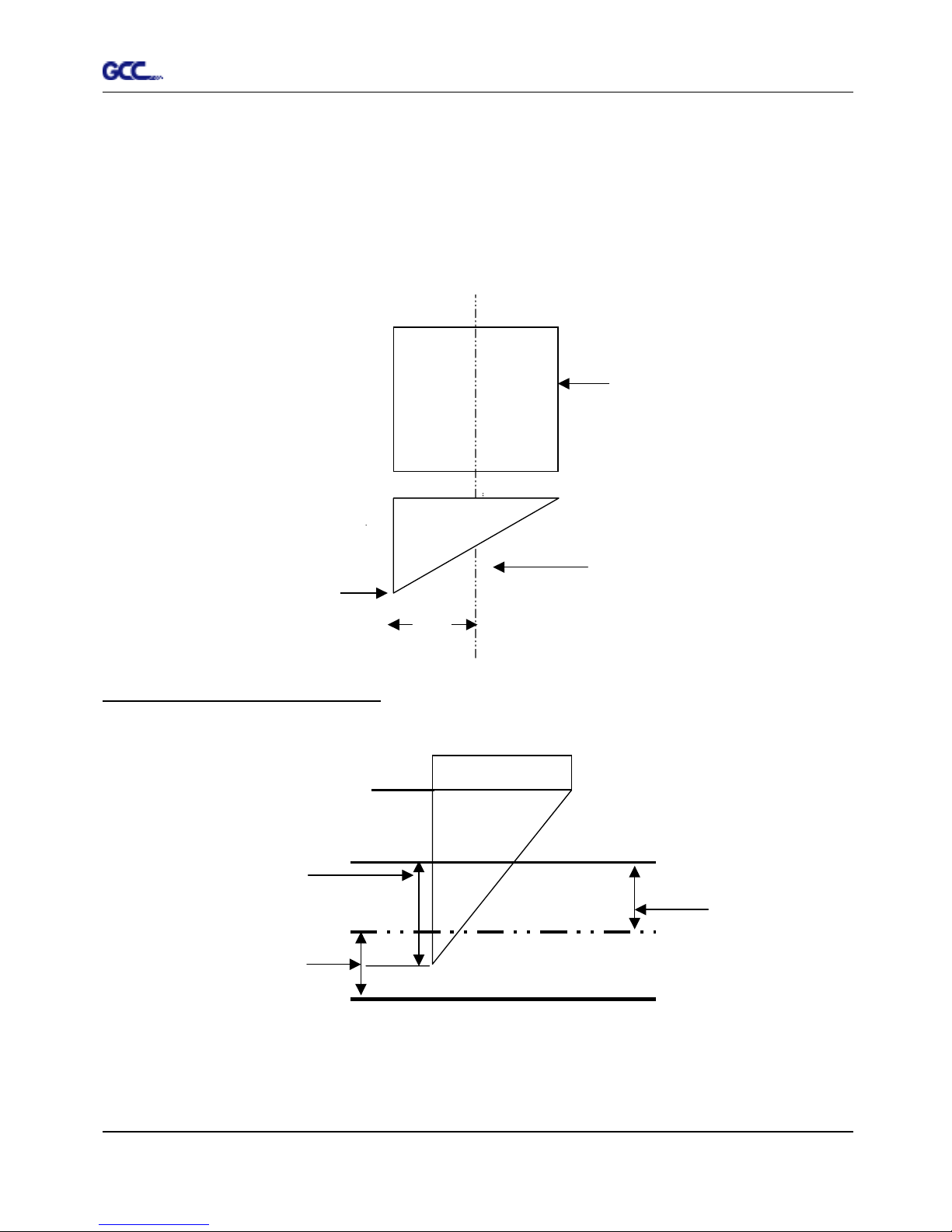
A generic term referring to the blade that cuts the sheet, the pen that does plotting, and the LED
bombsight (option) used for pointing to the reference point .
OFFSET is the distance that the blade tip is displaced from the centerline of the blade.
Protrusion Length of the Blade
Length of protrusion = t1 + t 2/ 2, but for your convenience you may just make it about 0.3~ 0.5 mm beyond the
blade holder tip.
Central line
Blade
Blade tip
offset
Thickness of the
base paper (t 2)
Thickness of
the film (t1)
Protrusion length
of the blade
Page 9

Jaguar II
User Manual
Table of Contents
TTaabbllee ooff CCoonntteenntts
s
Important Information I
Quick Menu V
The Specification for GCC Blade VI
About the Tool VII
1. – Setting Up Your Sign Cutting Plotter 1-1
1.1 Checking supplied items 1-1
1.2 Front View of SignPal Jaguar II 1-2
1.3 Back View of SignPal Jaguar II 1-3
1.4 Whole View of SignPal Jaguar II 1-3
1.5 Left Hand Side of Jaguar II 1-4
1.6 Right Hand Side of Jaguar II 1-4
1.7 Control Panel 1-5
2. – Installation and Operation Procedure 2-1
2.1 Installation 2-1
2.2 Stand & Flexible Media Support System Installation 2-2
2.3 Desktop Flexible Media Support System Installation 2-5
2.4 Blade Installation 2-7
2.5 Media Loading 2-9
2.5.1 Loading the Sheet Media 2-9
2.5.2 Loading the Roll Media 2-10
2.6 Tracking Performance 2-13
2.7 Adjusting the Cutting Force and Offset 2-14
3. – Description of Features 3-1
3.1 Setting up Menu—Jaguar II in on-line mode 3-1
3.2 Setting up Menu—Jaguar II in off-line mode 3-2
3.3 Description of menu items 3-3
4. – Connecting Cutting Plotters 4-1
4.1 Universal serial bus(USB) 4-1
4.2 Parallel Transmission 4-1
4.2.1 Connection to the Parallel Port 4-1
4.3 Serial Transmission 4-2
4.3.1 Connection to the Serial Port
(RS-232C)
4-2
4.3.2 Transmitting Data to plotter 4-2
4.4 Interface for Macintosh Computer 4-3
5. – Maintenance 5-1
5.1 Cleaning the cutting Plotter 5-1
5.2 Cleaning the Grid Drum 5-2
5.3 Cleaning the Pinch Rollers 5-2
6. – Trouble Shooting 6-1
6.1 Non Operational Problems 6-1
6.2 Operational Problems 6-2
Page 10

Jaguar II
User Manual
Table of Contents
6.3 Cutting Plotter Computer Communication Problems 6-3
6.4 Software Problem 6-4
6.5 Cutting Quality Problem 6-5
Appendix – Specification
Page 11
Jaguar II User Manual
1. Setting Up Your Sign Cutting Plotter
1.1 Checking supplied items
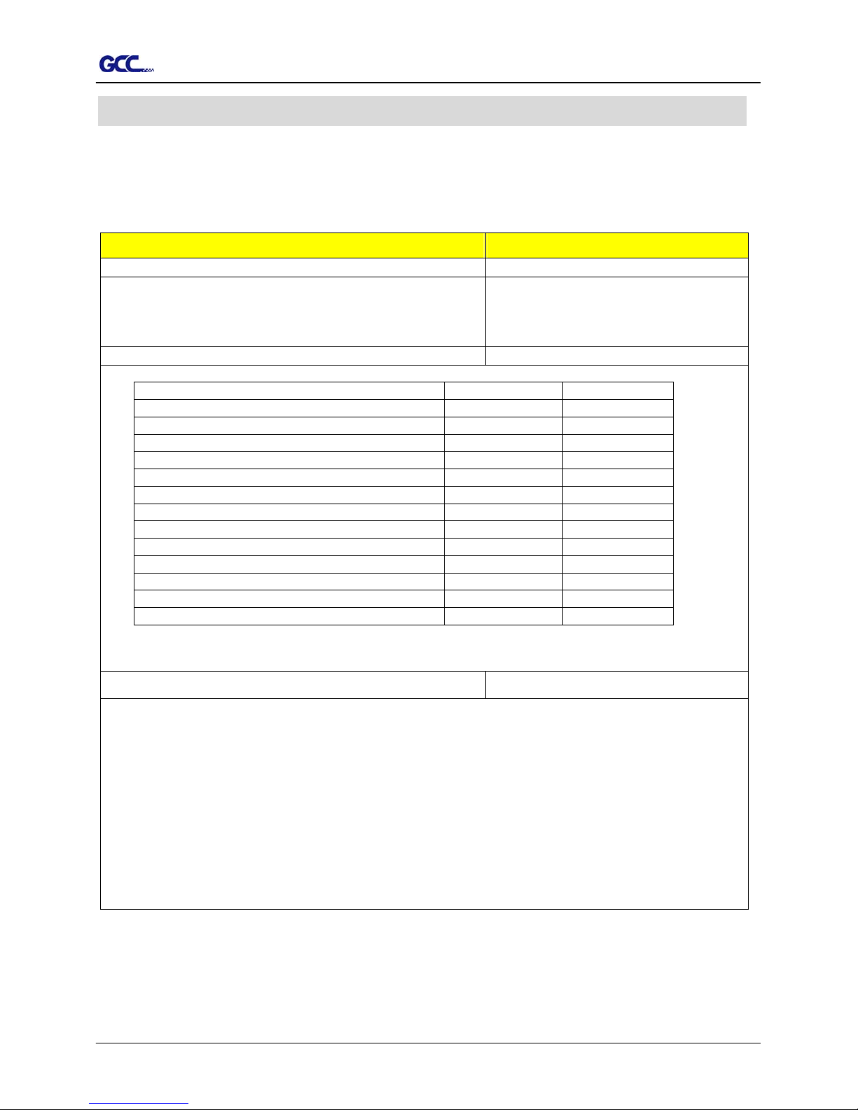
Please check carefully whether you have received all the items listed below. If you found
any item missing, please consult your local dealer.
SSttaannddaarrdd IItteemm
QQuuaannttiittyy
Cutting Plotter 1
Stand Set (Only for Jaguar JII-132S/101S/76S)
1 piece of H-shape stand
2 pieces of stands
1 piece of stand beam
1
Flexible Media Support System & Accessory Box 1
items 132S/101S/76S 61
1 set of Roll Media Flange (2 pieces)
1 set of Roll Holder (2 pieces)
1 set of Roll Holder Guide Bushes (4 pieces)
1 set of Roll Holder Support (2 pieces)
24 pieces of M6 screws
1 piece of M5 L-shape hexagon screw driver
1 piece of M6 L-shape hexagon screw driver
4 pieces of Hold Plugs
1 set of Desktop Support Brackets (2 pieces)
4 pieces of Plastic Foot
4 pieces of M4 screws
12 pieces of M6 screws
1 piece of M4 L-shape hexagon screw driver
Accessory Bag 1
1 piece of User’s Compact Disk
1 piece of AC power Cord
1 piece of data cable (RS-232C or print cable)
1 set of Blade Holder Assembly
1 piece of Blade
1 piece of Paper Sliter
1 piece of Cutting Pad for Vinyl cutting
1 Coil of Cutting Pad for paper cutting
1 piece of Tweez e rs
1 piece of Water-based Fiber-tip Pen
1 – Setting Up Your sign Cutting Plotter 1-1
Page 12
Jaguar II User Manual
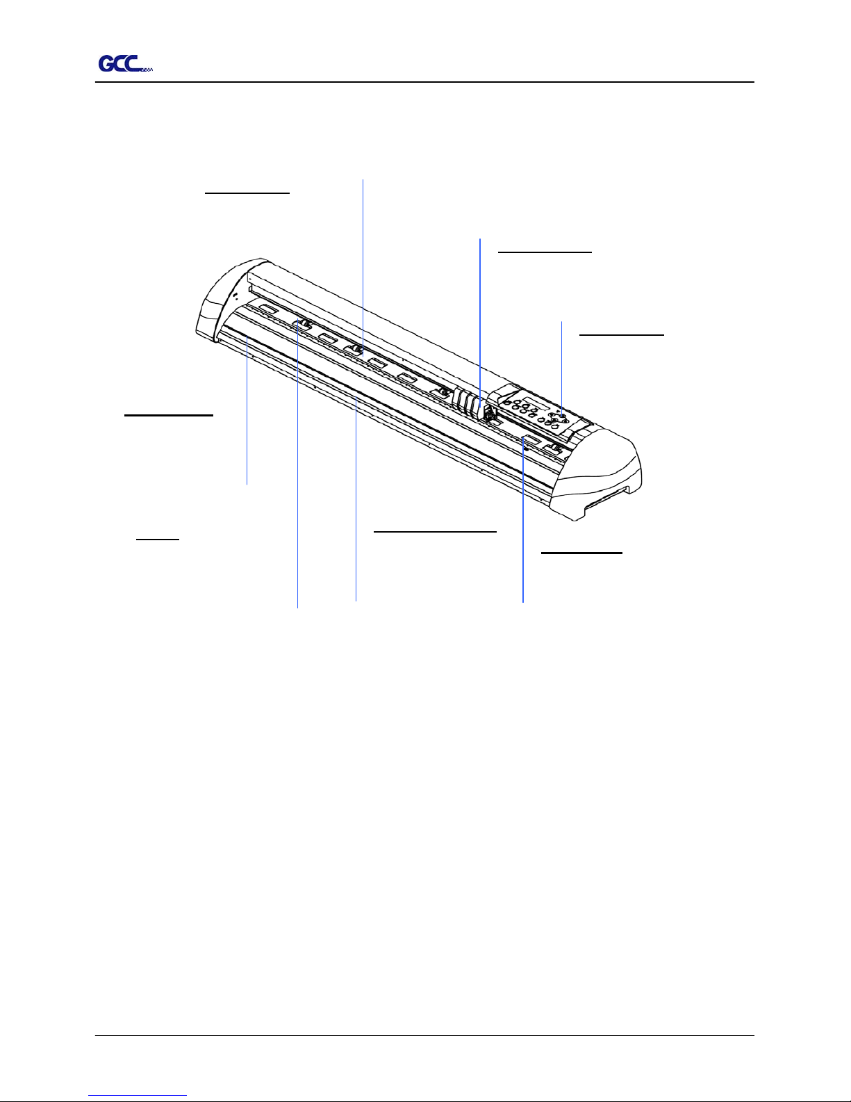
1.2 Front View of Jaguar (Figure 1-1)
Control panel – consists of 14
control keys and 1 LED and 1 LCM
showing messages and menus.
Platen -
p
rovides the
surface for holding an
d
supporting media while
performing cutting
SliterGroove –
sheets off the extra
media easily along
this groove.
Grid Drums move the
media back and fort
h
during operation.
Alignment Rulers -
Media can be aligned
with the clear guide line
marks
Tool Carriage –
p
erforms the
cutting with the installed blade
and
p
en.
Cutting Pad – provides the
protection of blade when the blade
is cutting.
Figure 1-1
1 – Setting Up Your sign Cutting Plotter 1-2
Page 13
Jaguar II User Manual
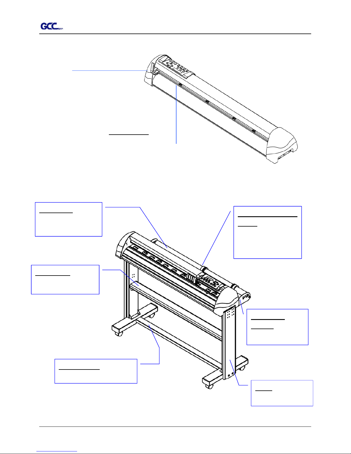
1.3 Back View of Jaguar (Figure 1-2)
Lever - raises o
r
lowers the pinc
h
rollers.
Pinch Rollers - hol
d
the media during cutting.
1.4 Whole View of Jaguar (
Figure 1-3)
e body.
Roll Holder
Support – supports
roll holders
Stand Beam –
stabilizes th
Stand - Supports the
cutting plotter body.
Roll Holder Guide
Bushes - Serve to keep the
roll media in place whe
n
media is pulled from the
roll.
Roll Holder - Holds an
d
supplies the roll media
for cutting.
H-shape Stand – Supports the
cutting plotter body.
Figure 1-3
Figure 1-2
1 – Setting Up Your sign Cutting Plotter 1-3
Page 14
Jaguar II User Manual
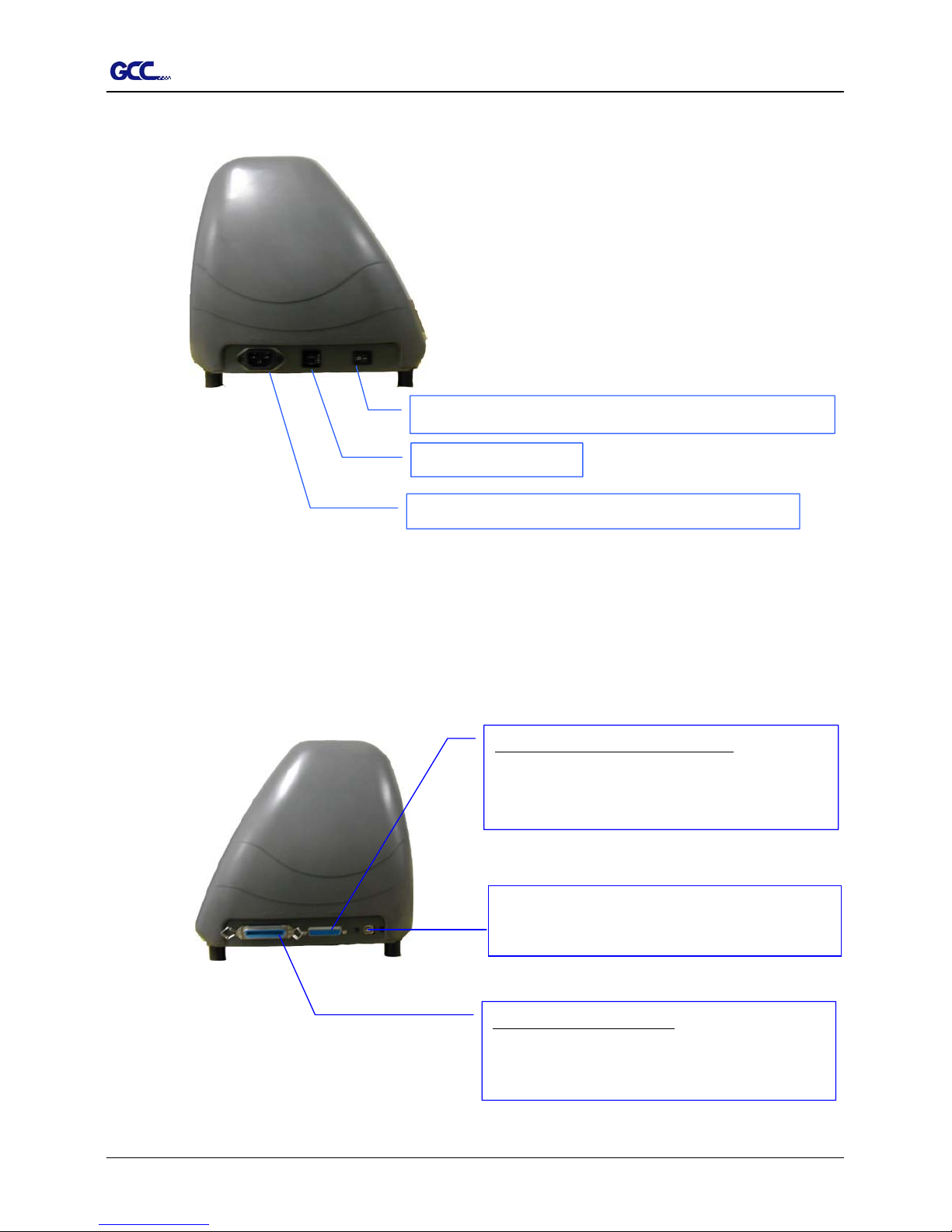
1.5 Left Hand Side of Jaguar (Figure 1-4)
Power Switch – On when switches to [I]; Off to [O]
AC Power Connector – used to insert the AC power cord.
Fuse – 3 Amp.
Figure 1-4
1.6 Right Hand Side of Jaguar (Figure 1-5)
Figure 1-5
USB Connector- used to connect the cutting
p
lotter to a computer through a USB cable.
Serial Interface Connector (RS232C) – used to
connect the cutting plotter to a computer through a
serial interface cable.
Parallel Interface Connector – used to connect the
cutting plotter to a computer through a parallel
interface cable
1 – Setting Up Your sign Cutting Plotter 1-4
Page 15
Jaguar II User Manual
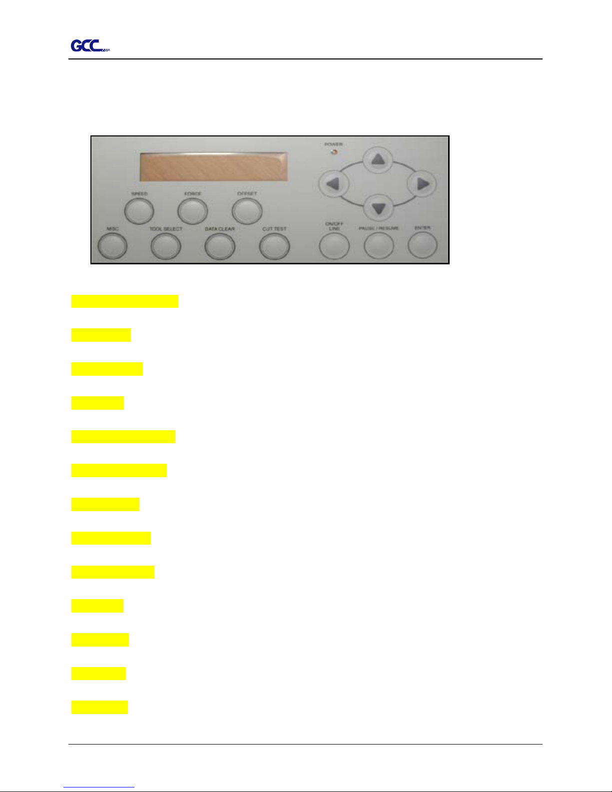
1.7 Control Panel (Figure 1-6)
Please refer to the Chapter3 – the description of operation for detailed explanation.
Figure 1-6
LCD Display Screen: various functional and error message are displayed here.
Power LED: it lights up when the power is on.
4 Arrow Keys: used to move the carriage or sheet or changing setting.
Enter Key: used to set item, registers the immediately preceding input value.
Pause/Resume Key: temporarily halts cutting in process or continues.
ON/OFF LINE Key: used to stop the cutting job or aborting the change of the setting.
Cut Test Key: executes a cutting test for verifying the blade force and offset are correct.
Data Clear Key: used to aborting the data being received.
Tool Select Key: used to selecting tools and setting the conditions.
Misc. Key: used to selecting items mentioned in Chapter 3.
Speed Key: used to selecting the cutting speed, up-speed, and cutting quality.
Force Key: used to select the cutting force.
Offset Key: used to adjust the setting value of the blade offset.
1 – Setting Up Your sign Cutting Plotter 1-5
Page 16

Jaguar II User Manual
Installation and Operation of Sign Cutting Plotter 2-1
2.1 Installation
Caution 1
Make sure the power switch is off before installing the cutting plotter.
Carefully handle the cutter to prevent any injuries.
Caution 2 Choosing a proper place before setting up the cutting plotter
Before installing your cutting plotter, select a suitable location, which meets the following
conditions.
The machine can be approached easily from any direction.
Keep enough space for the machine, accessories and supplies.
Keep the working area stable, avoiding sever vibration.
Keep the temperature between 5 and 40
℃
(41-104oF) in the workshop.
Keep the relative humidity between 30% and 70% in the workshop.
Protecting the machine from dust and strong air current.
Preventing the machine from direct sunlight or extremely bright lighting.
Caution 3 Connecting the Power Supply
Check the plug of the power cord to see if it mates with the wall outlet. If not, please contact
your dealer.
Insert the plug (male) into a grounded power outlet.
Insert the other end (female) of power cord into the AC connector of the cutting plotter.
2. Installation and Operation Procedures
Page 17
Jaguar II User Manual
Installation and Operation of Sign Cutting Plotter 2-2
2.2 Stand & Flexible Media Support System Installation
Step 1
Please examine supplied items in the accessory box of stand carton:
1 piece of M6 L-shape hexagon screw driver
1 piece of M5 L-shape hexagon screw driver
24 pieces of M6 screws
4 pieces of hold plugs
Step 2
Remove the plotter body and the accessories from the shipped carton.
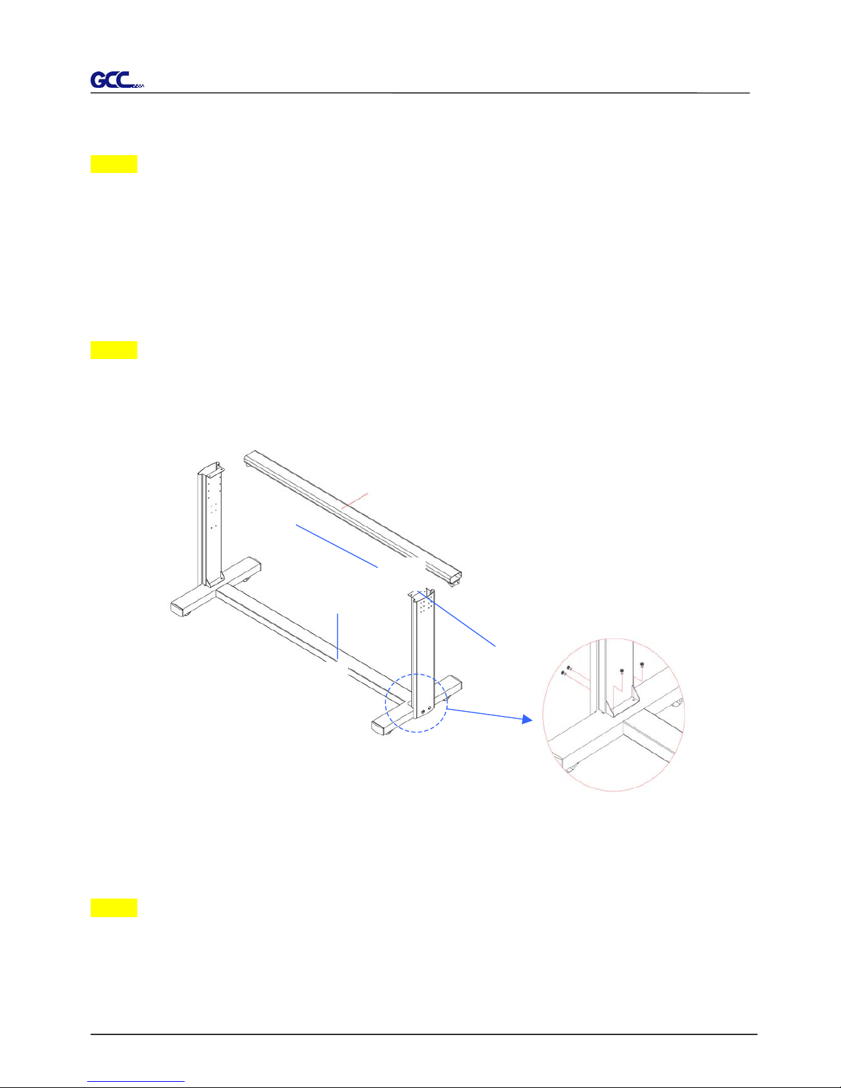
Place the stands upright on the H-stand and follow the number XYZ to assemble.
(See Figure 2-1 & 2-2)
Step 3
Then, connect PartY and X. Insert 4 screws into the holes on H-stand and fasten them as
shown in Figure 2-2.
Y
X
H-stand
Figure 2-1
Z Stand beam
Figure 2-2
Page 18
Jaguar II User Manual
Installation and Operation of Sign Cutting Plotter 2-3
Step 4
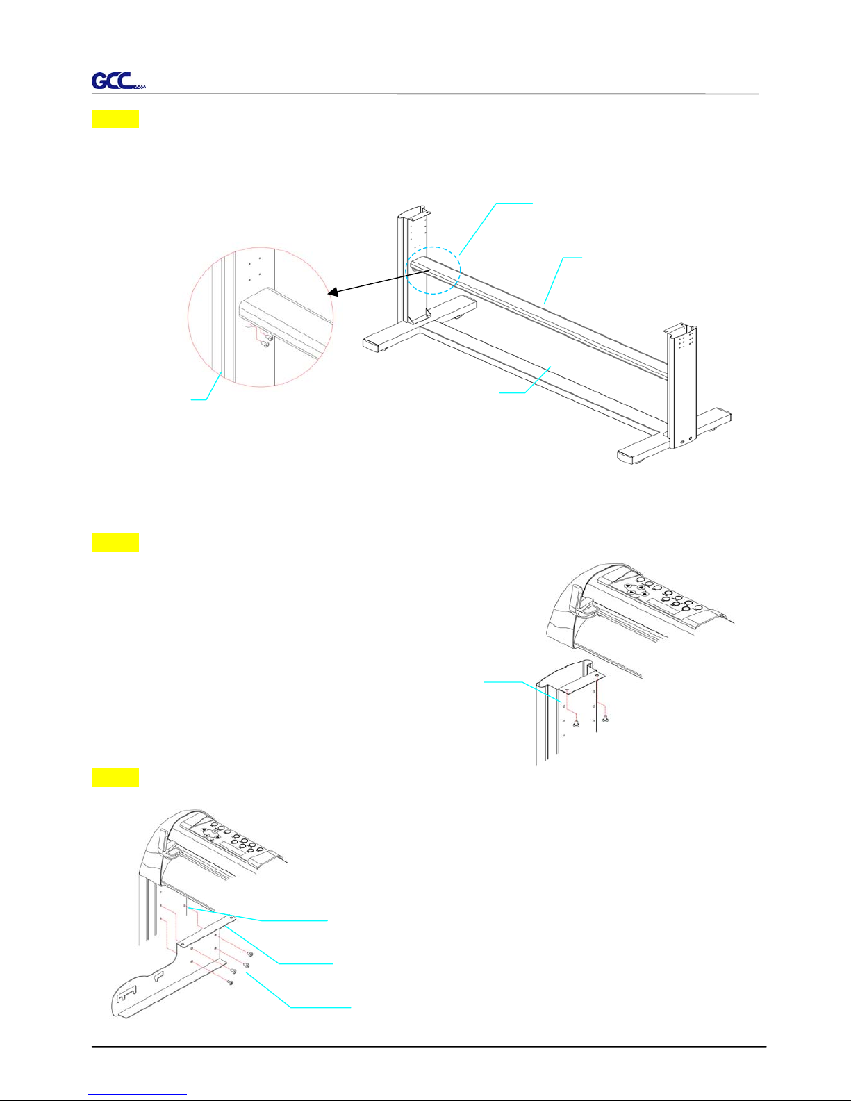
Position the stand beam perpendicularly to part Y and put the screws into the holes and tighten
them as Figure 2-3. Then the complete picture of stand will be like Figure 2-4.
Step 5
Remove the cutting plotter from the carton. Position your
stand under the plotter, and then insert the screws into the
holes on plotter’s bottom and tighten them up
as shown in Figure 2-5.
Step 6
Insert the roll holder support with the screws into the holes of the
stand, then tighten them up as shown in Figure 2-6. You could
decide roll holder support’s position by inserting into different
holes.
Figure 2-4 Figure 2-3
Zstand beam
Y stand
X H-stand
screw
screws
Figure 2-5
4 screws
6 screws holes
Roll holder support
Figure 2-6
Page 19
Jaguar II User Manual
Installation and Operation of Sign Cutting Plotter 2-4
Step 7
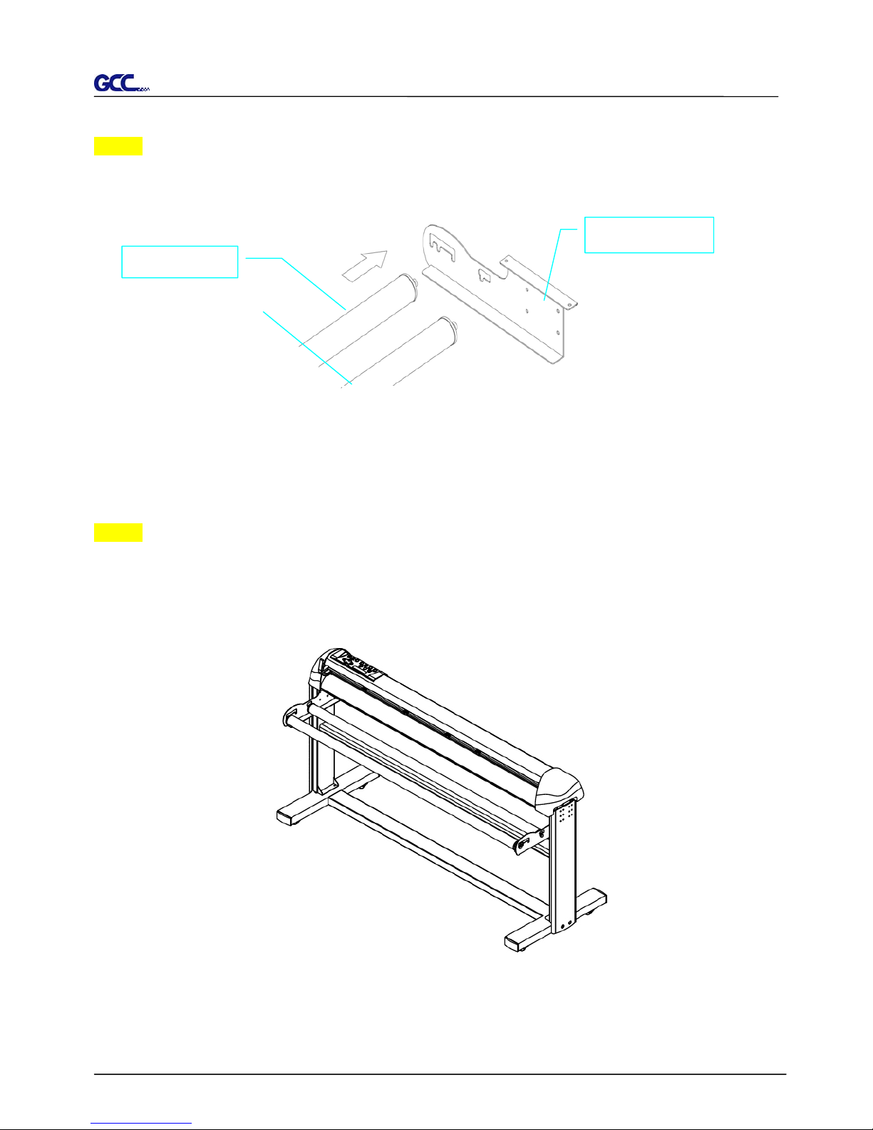
Place two roll holders into the holes in the roll holder support (Figure 2-7)
Step 8
Lastly, the complete picture will be shown like below. (see Figure 2-8)
Roll holder support
Roll holders
Figure
Figure 2-8
Page 20
Jaguar II User Manual
Installation and Operation of Sign Cutting Plotter 2-5
Figure 2-3-1
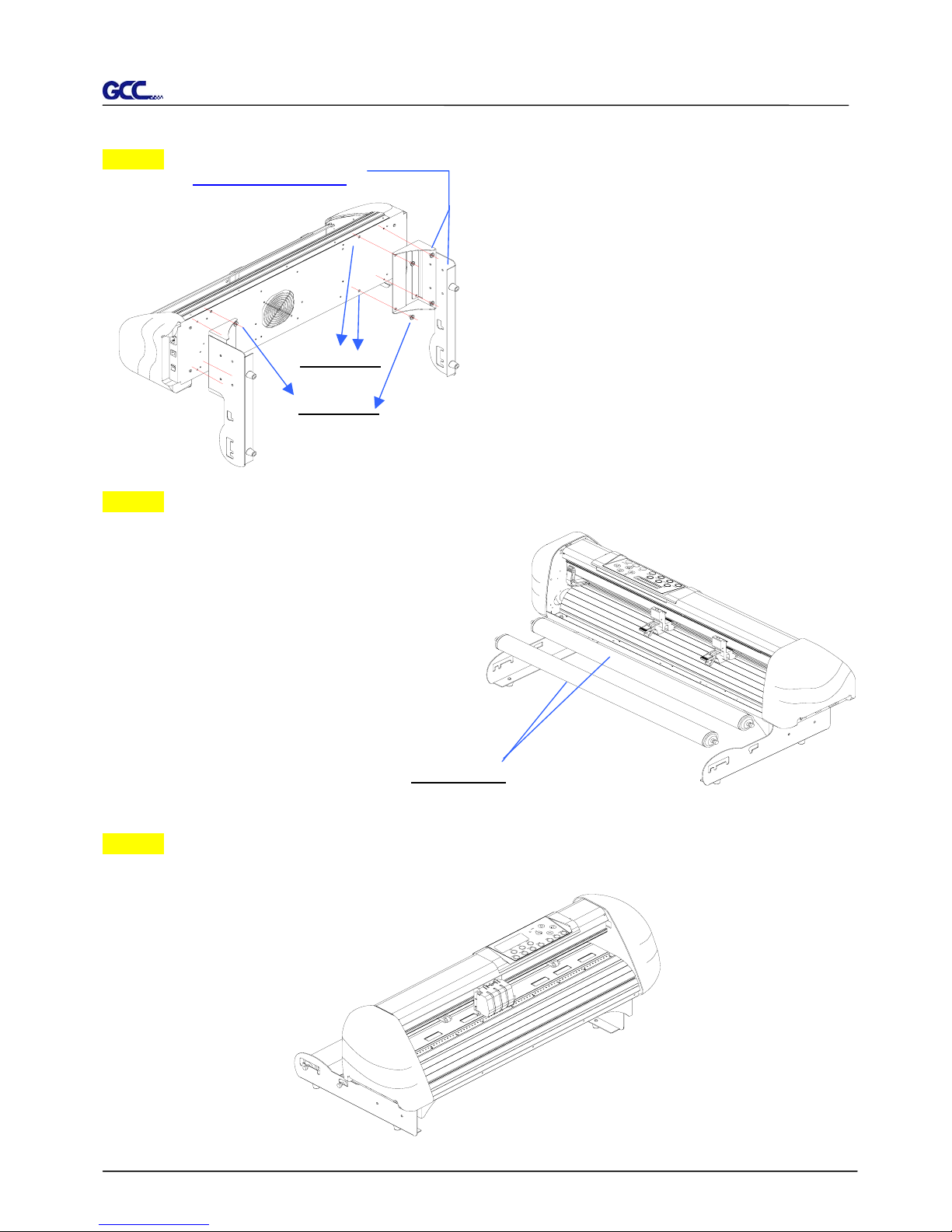
2.2 Desktop Flexible Media Support System Installation (Jaguar61)
Step 1
Please examine the following items in stand carton’s accessory box:
1 set of Roll Media Flange (2 pieces)
1 set of Roll Holder (2 pieces)
1 set of Roll Holder Guide Bushes (4 pieces)
1 set of Roll Holder Support (2 pieces)
1 set of Desktop Support Bracket (2 pieces)
4 pieces of Plastic Foot
4 pieces of M4 screws
12 pieces of M6 screws
1 piece of M4 L-shape hexagon screw driver
1 piece of M5 L-shape hexagon screw driver
1 piece of M6 L-shape hexagon screw driver (for adjusting the screws of Roll Holders)
Step 2
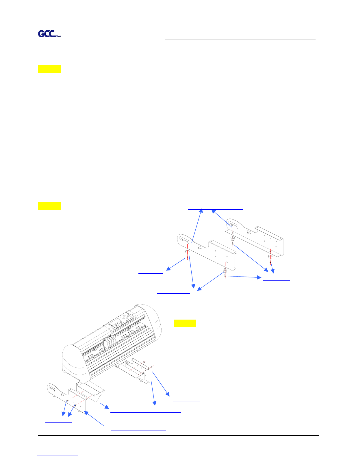
Put the 4 Plastic Foot under the Roll Holder
Support and insert the M4 screw into the hole of
Plastic Foot and tighten them with the M4
L-shape screw driver. (Figure 2-3-1)
Step 3 Position the Desktop Support Brackets
beside the Roll Holder Support and insert M6
screws into the Roll Holder Support and tighten
them with M5 L-shape screw driver. (Refer to
Figure 2-3-2 at the left).
Roll Holder Support
Plastic Foot
M4 screw
M4 screws
Desktop Support Brackets
M6 screws
Roll Holder Support
M6 screws
Figure 2-3-2
Page 21
Jaguar II User Manual
Installation and Operation of Sign Cutting Plotter 2-6
Step 4
Put the bottom of machine in lateral, and
position the Roll Holder Assembly beside the
bottom of the machine. Then, insert the M6
screws into the holes of Roll Holder support
assembly and tighten them with M5 L-shape
screwdriver. Like Figure 2-3-3.
Step 5
Place the 2 roll holders into the holes of Roll
Holder Support (See Figure 2-3-4).
Step 6
The complete Desktop Media Support System will be shown as in Figure 2-3-5.
Figure 2-3-5
M6 screws
Screw holes
Roll Holder Assembly
Figure 2-3-4
Roll Holders
Figure 2-3-3
Page 22
Jaguar II User Manual
Installation and Operation of Sign Cutting Plotter 2-7
2.3 Blade Installation
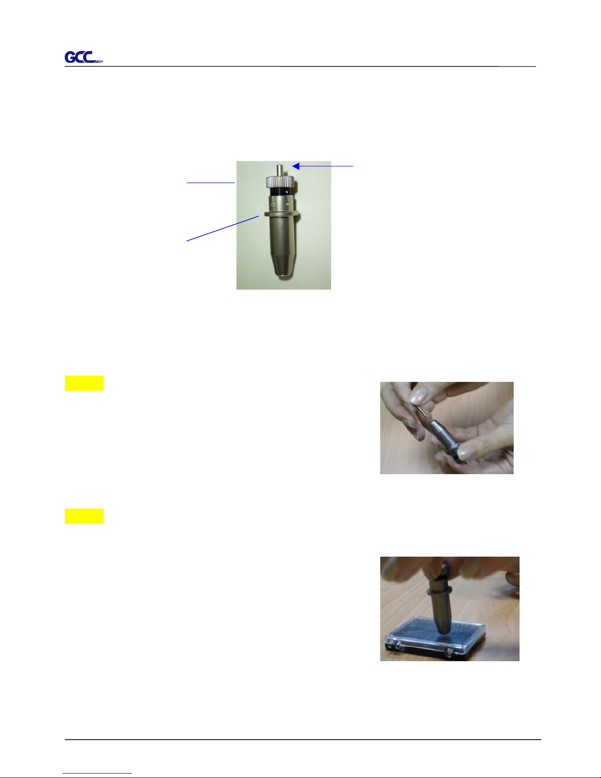
Figure 2-10 is the illustrator of the blade holder. Insert a blade into the bottom of the blade
holder and remove the blade by pushing the pin. Make sure that your fingers are away from
the blade tip.
Step 1
Install blade (Figure 2-11).
Step 2
Push the blade to the bottom of the blade holder. (Figure 2-12).
Figure 2-10
Pin
Outward ring
Adjustment depth knob
Figure 2-11
Figure 2-12
Page 23
Jaguar II User Manual
Installation and Operation of Sign Cutting Plotter 2-8
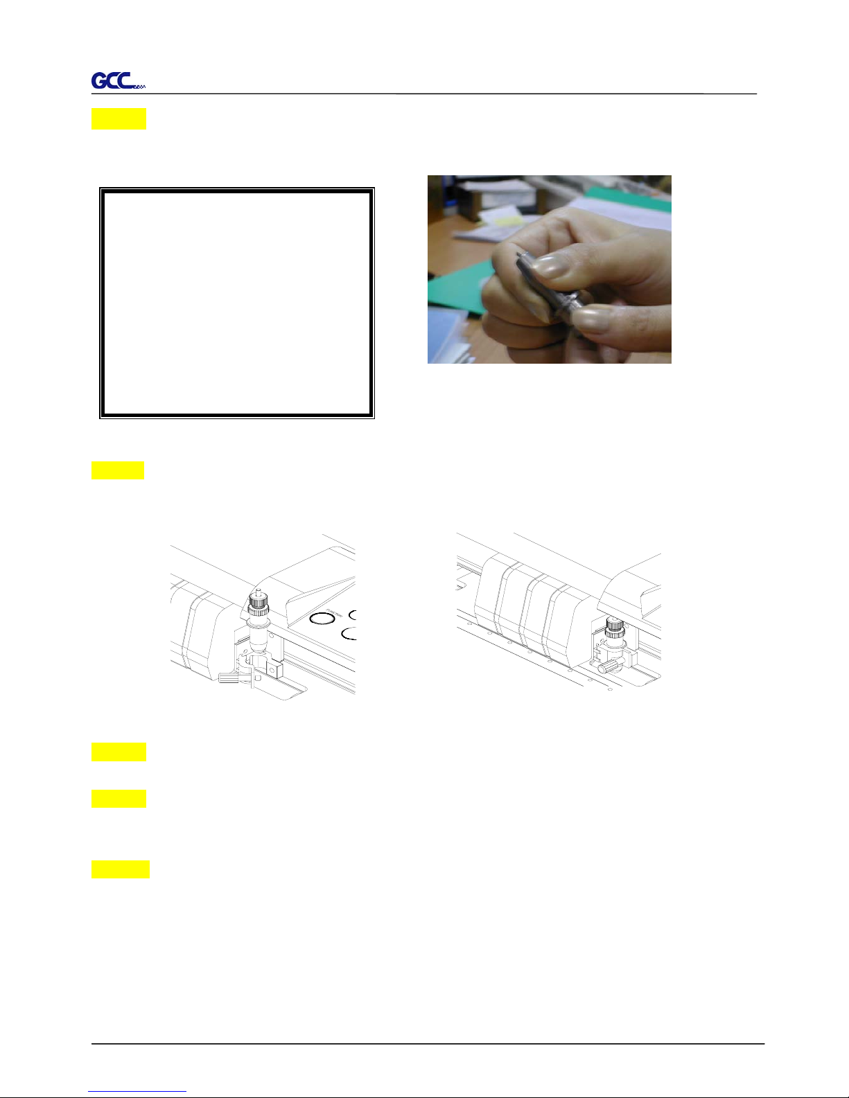
Step 3
Adjust the blade tip to suitable length by screwing “Blade tip adjustment screw” clockwise or
count-clockwise. (Figure 2-13).
Step 4
Insert the blade holder into tool carriage. Please note the outward ring of the holder must put
into the grooves of carriage firmly (see Figure 2-14), then fasten the case (Figure 2-15)
Step 5 Use the reversing steps to remove the blade holder.
Step 6 Eject the blade. Push “Blade eject pin” to eject blade when the blade needs to be
replaced.
Caution
The blade will lose its sharpness after a period of usage, the cutting quality might be affected.
By increasing the cutting force, it might do the trick. However, once the blade is worn out and no
longer provides a reliable cutting, you should replace a new one. The blade is consumable and
must be replaced as often as necessary to maintain the cutting quality. The quality of the blade
deeply affects cutting quality. So be sure to use a high quality blade to ensure good cutting
results.
Tips:
“The proper length” means the
blade’s length is adjusted 0.1mm
more than film’s thickness. That is, i
f
the thickness of film is 0.5mm, the
n
b
lade’s length is properly adjuste
d
0.6mm and it can completely cu
t
through the film layer yet avoi
d
penetrating the backing.
Figure 2-14
Figure 2-14
Figure 2-13
Page 24
Jaguar II User Manual
Installation and Operation of Sign Cutting Plotter 2-9
Figure 2-19
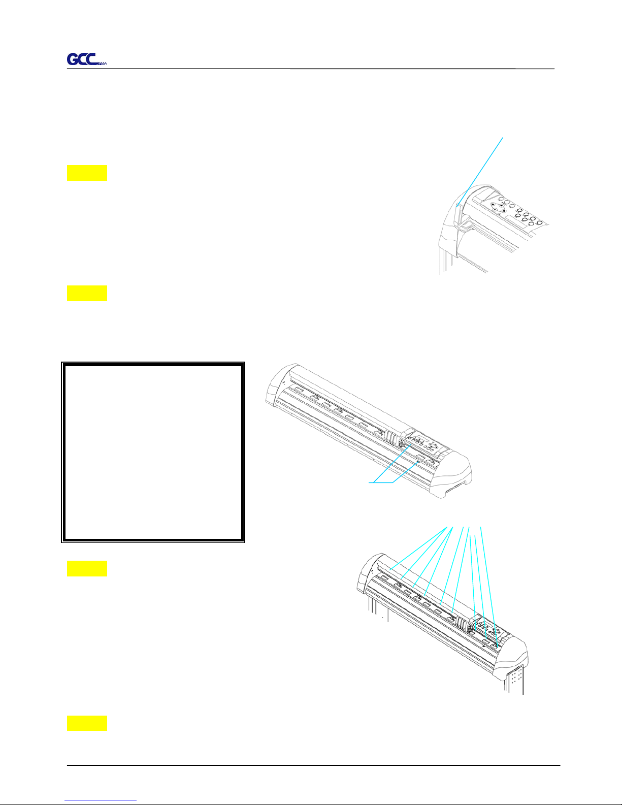
2.4 Media Loading
2.5.1 Loading the Sheet Media
To load the media properly, please follow the procedures listed below:
Step 1
Use the lever on the upper right side of the cutting plotter to raise or
lower down pinch rollers. Pull the lever forward until it makes a clicking
sound then the pinch rollers are raised (Figure 2-17).
Step 2
Load your media on the platen and slide it under the pinch rollers from either the front side or
the backside. The color alignment rulers on the platen extension will help you to adjust the
media precisely.
Step 3
Then move the pinch rollers manually to the proper
position. Be sure the pinch rollers must be positioned
above the grid drum. The white marks on the main
beam will remind you where the grid drums are
(Figure 2-19).
Step 4
Push the lever backward to lower down the pinch rollers.
Figure 2-17
Lever
Note: Be sure that the media
must cover the paper sensors on
the platen when loading the
media. At least one of the two
paper sensors (Figure2-18)
should be covered. Once the
media covers the sensor, the
cutting plotter will size the
media’s width and length
automatically.
Paper
Figure 2-18
White
Page 25
Jaguar II User Manual
Installation and Operation of Sign Cutting Plotter 2-10
Step 5
Turn on the power, the tool carriage will measure the size of the media automatically. And the
plotting cutter begins to work.
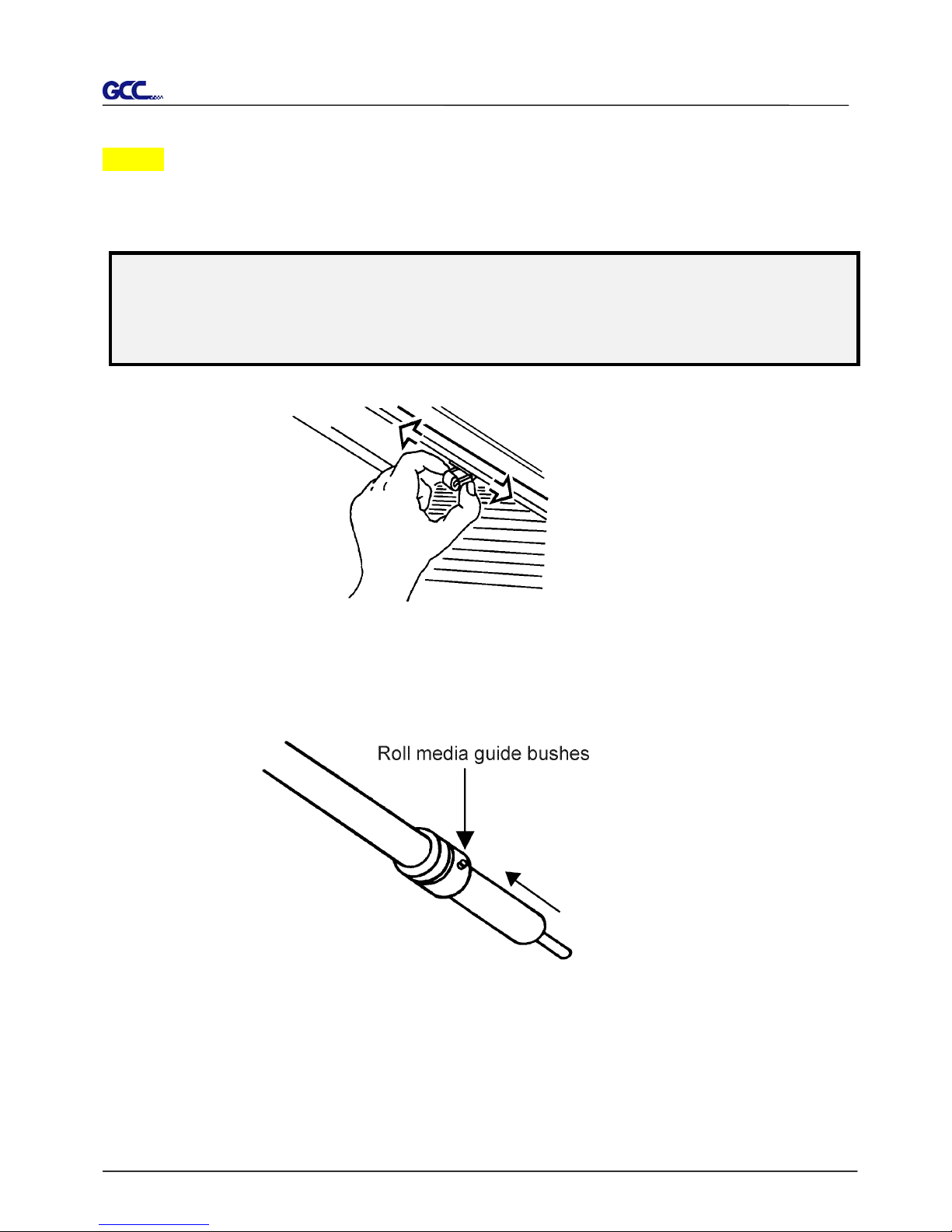
Note:
1. Always adjust the position with the pinch roller raised.
2. Move the pinch roller by applying force at the rear portion of the pinch roller support.
3. Do not move it by holding its front rubber roller (Figure 2-20).
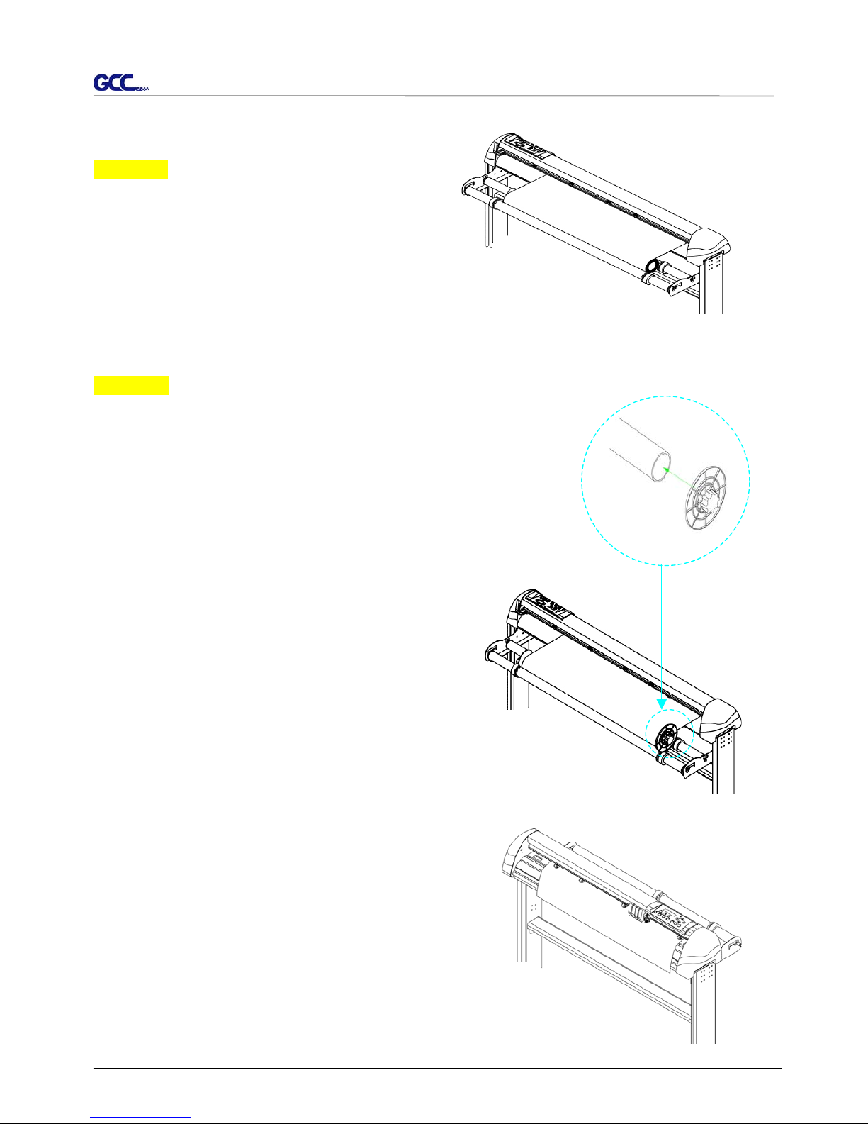
2.5.2 Loading the Roll Media
1. Put the roll media guide bushes on two roll holders (Figure 2-21).
Figure 2-20
(X)
Incorrect
Figure 2-21
Page 26
Jaguar II User Manual
Installation and Operation of Sign Cutting Plotter 2-11
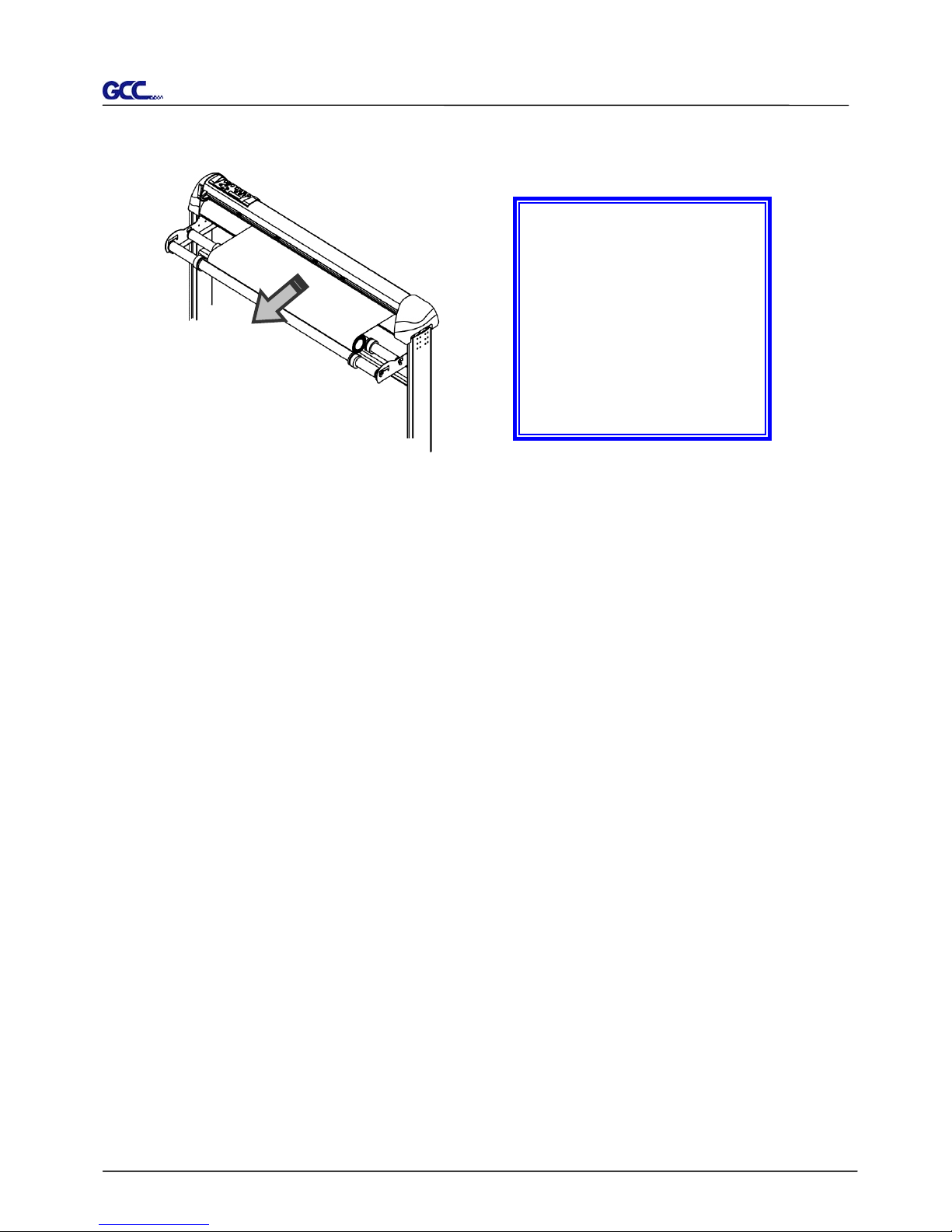
Figure 2-22
2.
Option A (Recommended)
Insert the two roll holders into the roll media
support set then place the roll media directly
between the two roll holders (Figure 2-22).
Option B (Use the media flanges)
Insert a roll media flange at the end of each roll media and tighten
the thumbscrew until the roll media is firmly gripped (see Figure
2-23
).
Then put the roll media on the roll holders. Adjust
the position of the roll media ensure that media
flanges are able to run in the grooves of media
guide bushes. (Figure 2-24)
3.
Load the media on the platen. Please refer to “2.4.1.
Loading the sheet media”. After loading the roll media,
flatten the media on the platen and hold the front edge of
the roll media firmly (Figure 2-25).
Figure 2-23
Figure 2-25
Figure 2-24
Page 27
Jaguar II User Manual
Installation and Operation of Sign Cutting Plotter 2-12
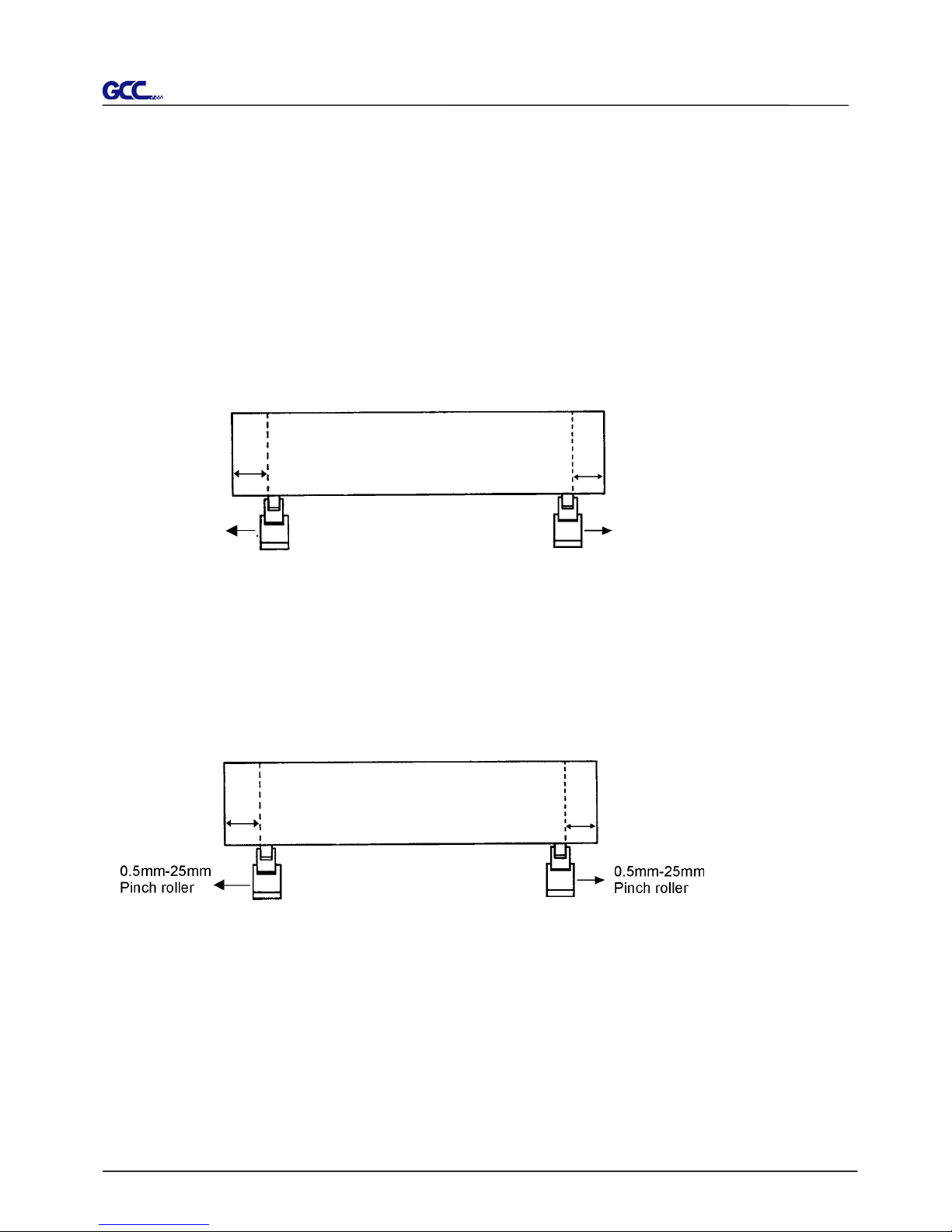
4. Then turn the roll downward to make an equal tension across the media (Figure 2-26)
5. Move the pinch rollers to the appraise location and please note that the pinch rollers must be
positioned above the grid drums.
6. Push the lever backward to lower down the pinch rollers.
7. Fixes roll media guide bushes on the roll holder to secure the roll media
8. Turn on the power switch, the tool carriage will sizing the media automatically.
Then the cutting plotter is ready to work.
9. Use the reverse steps to remove the media.
Note :
Make sure that the media
tension is equally distributed
from left to right. If the media
were not tighten enough
against the platen, it would
cause tracking problems!
Figure 2-26
Page 28
Jaguar II User Manual
Installation and Operation of Sign Cutting Plotter 2-13
2.6 Tracking Performance
In order to achieve the best tracking performance for a long plot, we recommend some
significant media loading procedures described as follows:
1. If the media length is less than 4 m, leave the margin of 0.5mm—25mm in the left and right
edges of the media (see Figure 2-27).
2. If the media length is greater than 4m, leave at least 25mm margin on the left and right
edges of the media (see Figure 2-28).
Please refer to the paragraph “Important Information” at the beginning of the book.
Figure 2-27
Figure 2-28
Pinch roller
Pinch roller
0.5mm - 25mm
0.5mm - 25mm
> or = 25mm
> or = 25m
m
Page 29
Jaguar II User Manual
Installation and Operation of Sign Cutting Plotter 2-14
2.7 Adjusting the Cutting Force and Offset
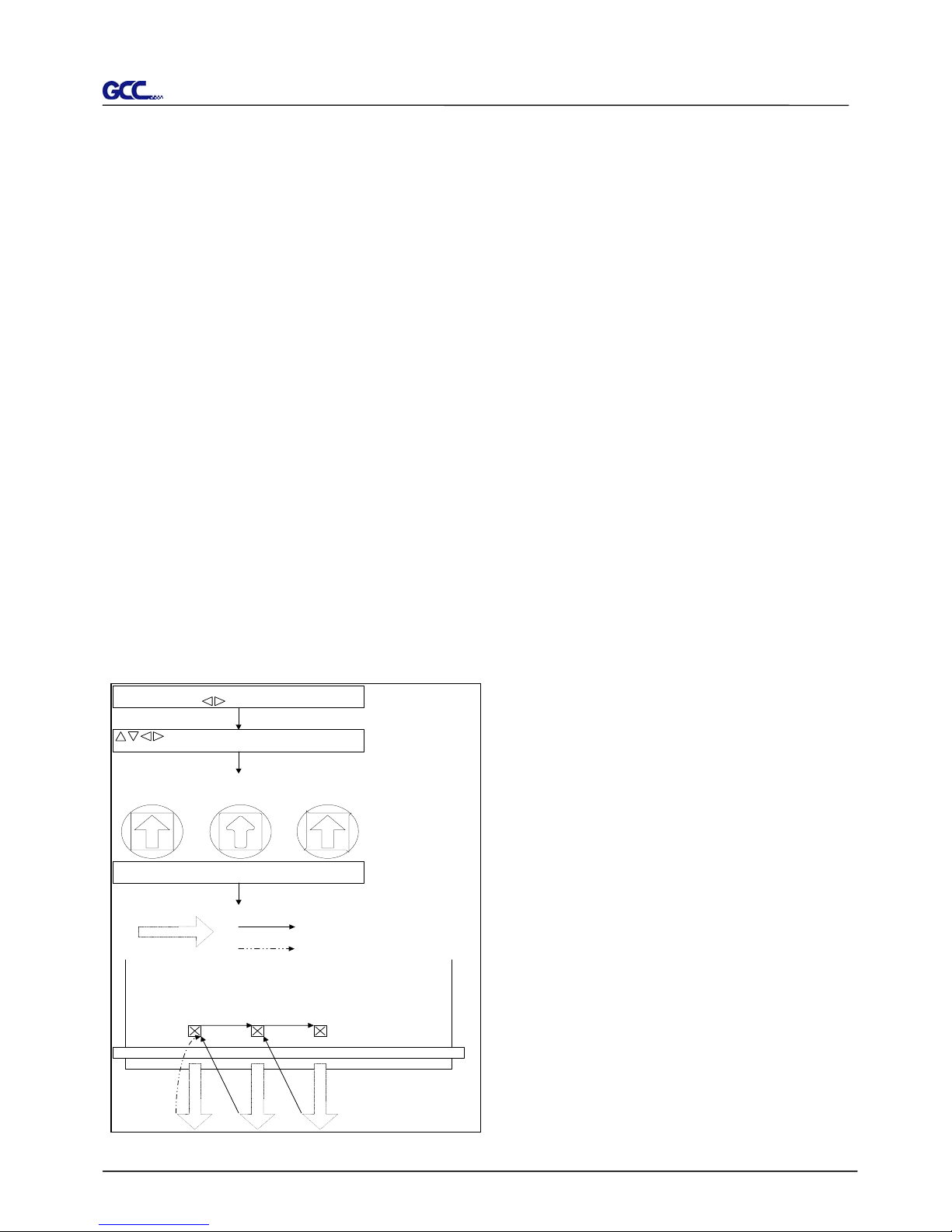
Before sending your designs for cutting, you may perform a “cut test” to generate satisfactory
cutting results.
“Cut Test” should be repeated until the appropriate cutting conditions for the media are
discovered.
After sizing the media, press [CUT TEST] button to select the “square cut”, and press [ENTER
KEY] to confirm.
The default cutting force and offset value of the cutting test are 80gf and 0.275mm respectively.
Press [ARROW KEY] to move the tool carriage to the position where you like. Then, press the
[ENTER KEY] to perform Cut Test.
Note: At the same time, the new origin is also set at the cutting test position.
When the cutting test is completed, a pattern appears. Peel off the pattern to see if it can be
easily separated from the media base. If yes, the setup tool force is appropriate. If not or cut
through the back paper, press [FORCE KEY] to adjust the tool force until an optimum force is
obtained.
If the pattern appears to be BB or CC layout,
press [OFFSET KEY] to adjust the offset
value until AA pattern discovered.
Squa r e Cut
Press ENTER _KEY
AA CCBB
Press ENTER _KEY
En t e r:OKSe l ec t :
Mo v e t t ecu
XY::
M
st
Squa r e Cu t
Press SPEED_K EY,
FORCE_KEY,
OFFSET_KEY to setup
or
Press arrow keys to
desired position for next
square cut
En t e r:OK
Con t
NN: C CELA
Machine
3mm
80 mm
3mm
80 mm
Press ENTER _KEY
80 mm
Finish square cut
Press
ENTER_KEY
Press
CANCEL_KEY
inous
Page 30
Jaguar II User Manual
3. Descriptions of Features
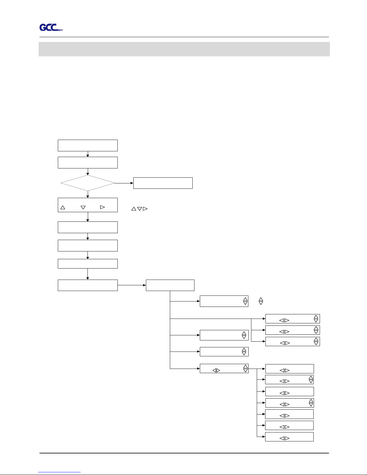
This chapter describes the button operation with the LCM menu flowcharts of Jaguar II. When
the cutting plotter is ready for use as described in Chapter 1 & 2, all functions are under default
parameters.
3.1 Setting up Menu—Jaguar II in on line mode
Power On
Firm w a re V -.-Copyright 2002
In itia liz in g -- -c m
Cutter please wait
Media check
Place Media and Lower
down the lever
Roll Edge Single
Ke y K ey K e y
Sizing Media Width
Lever U p to Abort
Siziing Media Length
Lever U p to Abort
S ---.- F ---.- O -.-- M
L:-----.-- W : ----.--
Top m enu
Data In Processing
Sending data
Pause
Setup Resume
[PAUSE]
Force: 80 gf
O K : E N T E R
[Fo rc e k e y]
Jaguar II in processing
U s e to sele c t
Us e to se lect; [E NTE R]to e nab le the se tting
O ffse t: 0 .27 5 m m
O K : E N T E R
Clear data mem ory
N: Cancel OK: ENTER
1S:72 F:80 O: 0.275 M
S ele ct O K: E N T E R
[O ffse t k ey ]
[Data Clear]
[Tool Select]
Speed: 72cm/s
S ele ct: O K: E N T E R
[Speed Key]
Up Speed: 72cm/s
S ele ct: O K: E N T E R
Q u ality: N o rm al
S ele ct: O K: E N T E R
Set Sm oothing Cut
S ele ct: O K: E nte r
Set Tangetial Mode
S ele ct: O K: E nte r
P ou n cin g 0 .00 m m
S ele ct: O K: E nte r
Panel Setup
S ele ct: O K: E nte r
O ve rC u t: 0.0 0 m m
S ele ct: O K: E nte r
Restore default ?
S ele ct: O K: E nte r
Save parameter ?
S ele ct: O K: E nte r
Description of Operation 3-1
Page 31
Jaguar II User Manual
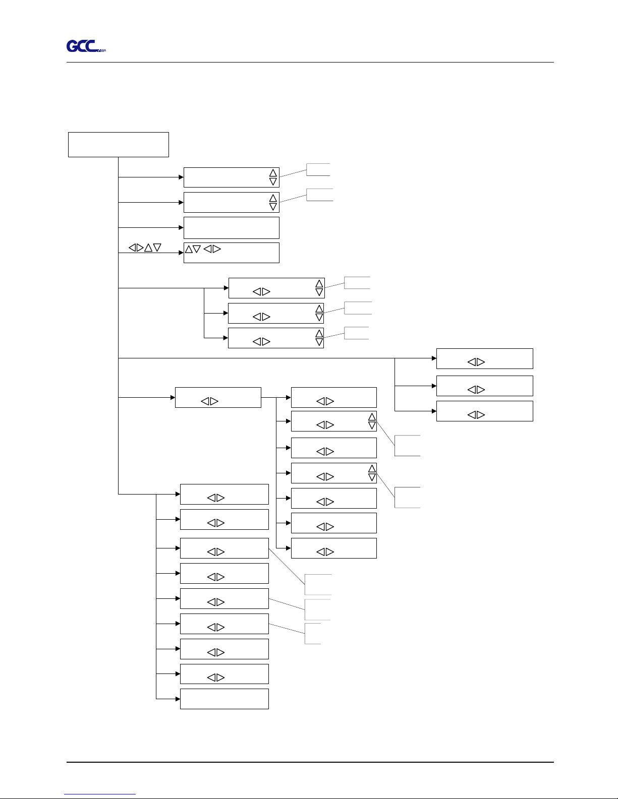
3.2 Setting up Menu—Jaguar II in off line mode
Press[ON/OFF LINE] switch to offline mode
Offline For
System Setup
[Force Key]
[OFFSET KEY]
[Data Clear ]
[ ]
[Speed Key]
[Cut Test]
[Tool Select]
[Misc]
Force: 80 gf
? OK : Ente r
Offset 0.275 mm
O K: Ente r
Clear Data Memery
N: Cancel OK: E nter
M ove Origin
X: Y:
Speed: 72cm/s
Selec t: OK: E nter
Up S peed: 72cm/s
Selec t: O K: E nter
Quality: Normal
Selec t: OK: E nter
Square Cut
Selec t: OK: En ter
Repeat Last Plot
Selec t: OK: En ter
Mark positions
Selec t: OK:En ter
Auto Unrolled Media
Selec t: OK:Enter
Media Back & Forth
Selec t: OK: Enter
Paper Saving Mode
Selec t: OK:Enter
Set Comm unication
Selec t: OK: Enter
Select Language
Selec t: OK: Enter
Sele ct U nits
Selec t: OK: Enter
Scale Length
Selec t: OK:Enter
Scale Width
Selec t: OK: Enter
1S: 72 F:80 O: 0.275 M
Selec t O K: E nter
Set Smoothing Cut
Select: OK: Enter
Set Tangetial Mode
Select: OK: Enter
Pouncing 0.00mm
Select: OK: Enter
Panel Setup
Select: OK: Enter
Speed: 3-153cm/s with an increment of 3cm/s
Upspeed: 3-153cm/s with an increment of 3cm/s
Draft, Fair, Norm al, Fine, Small Letter
0-600gram with an increment of 5 gf
0.000-1.000mm with an increment of 0.025mm
English, Spanish, Italian, Deutsch, Japanese,
Portuguese, Polish, Turkish, French
Metric (cm / gf) o r English
measurement(feet/ounce)
Firmware: x.x.xx
FPGA: Vx.x m m /dd/yy
OverCut: 0.00mm
Select: OK: Enter
Restore default ?
Select: OK: Enter
Save parameter ?
Select: OK: Enter
OverCut: 0.00-1.00 mm with an increment of
0.05 mm
Pouncing: 0-200 mm with an increment of
1 mm
Both Expanded Mode, Length Expanded Mode,
Width Expanded Mode, Both Unexpanded Mode
Description of Operation 3-2
Page 32
Jaguar II User Manual
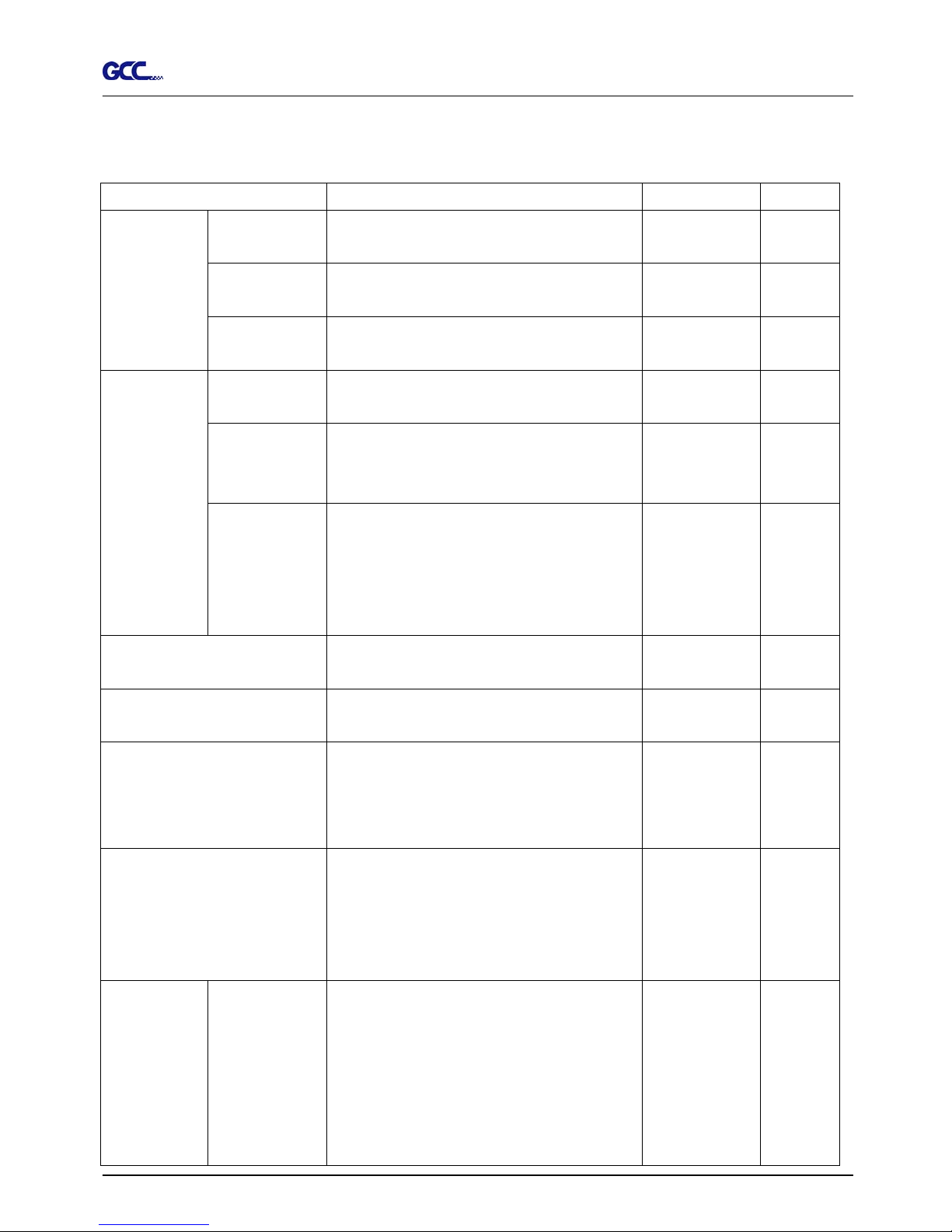
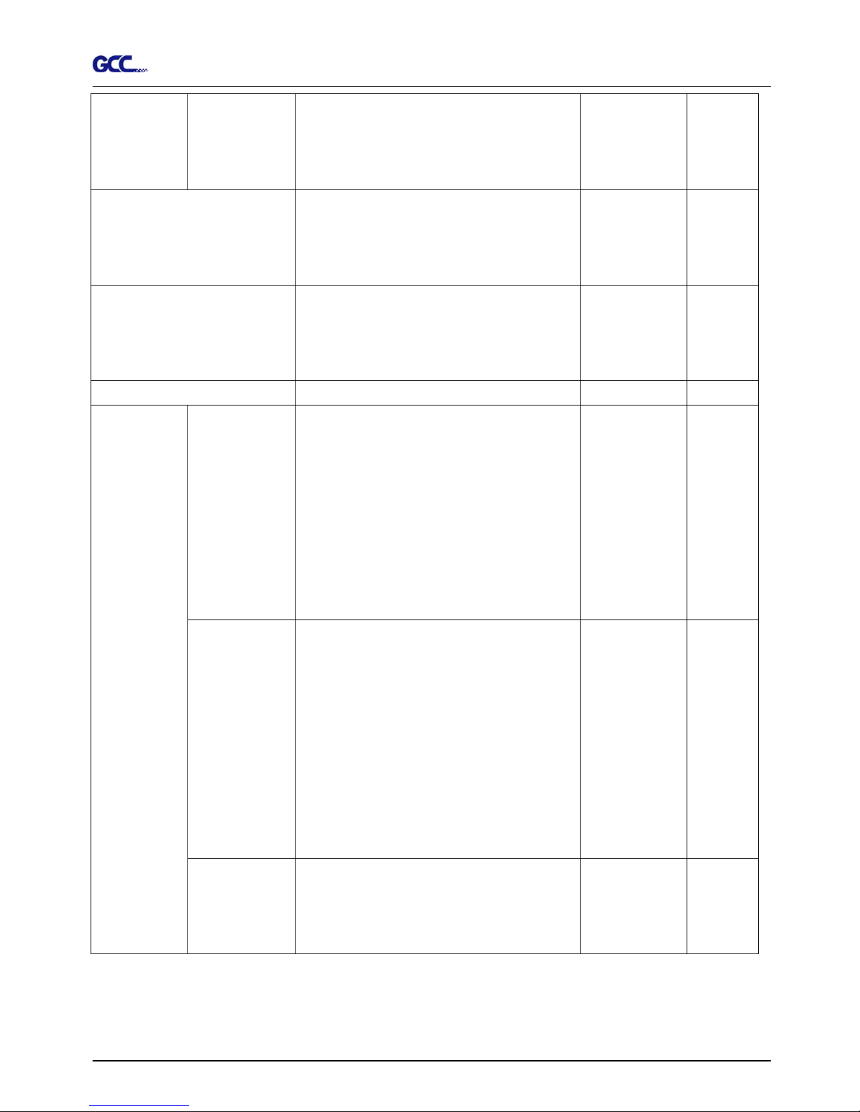
3.3 Description of Menu Items
This describes the items and functions available when you press
Menu or Key Function Setting Default
Roll: Sizing media width. Tracking
25 meters
Edge Sizing media width and pull the media back until
the front paper sensor open
Tracking
25 meters
Media sizing
Single Sizing media width and length Tracking
10 meters
Speed This sets the speed when the blade is down and
moves for cutting.
3-153cm/s
Step (3cm/s)
72cm/s
Up Speed This sets the speed when the blade is raised
and moves to the next position for cutting during
a cutting operation
3-153cm/s
Step (3cm/s)
72cm/s
[Speed Key]
Cutting Quality This sets the cutting quality.
When cutting small letter, set it to Small letter.
When cutting at very fast speed, please set it to
“Draft”. For normal operation please set it to
“Normal”.
Draft
Fair
Normal
Fine
Small Letter
Normal
[Force Key]
This set the force for the blade during cutting. 600gram
5 gram/step
80 gram
[Offset Key]
This set the offset value for the blade during
cutting.
0.000-1.000mm 0.275mm
[Arrow Key]
1. Move the carriage position on x-axis and
y-axis
2. Choose the functions and change the value
of the setting.
[Enter]
1. Press it to effect the displayed parameters.
The displayed parameters will be saved
automatically.
2. To set a new origin at the present tool
carriage position.
[Enter] Set New Origin
In “offline” mode,
Press [ARROW KEY] to move the tool carriage
to the desired location. Then, press [ENTER
KEY] to set new origin.
While moving, the x-axis and y-axis are
displayed.
Description of Operation 3-3
Page 33
Jaguar II User Manual
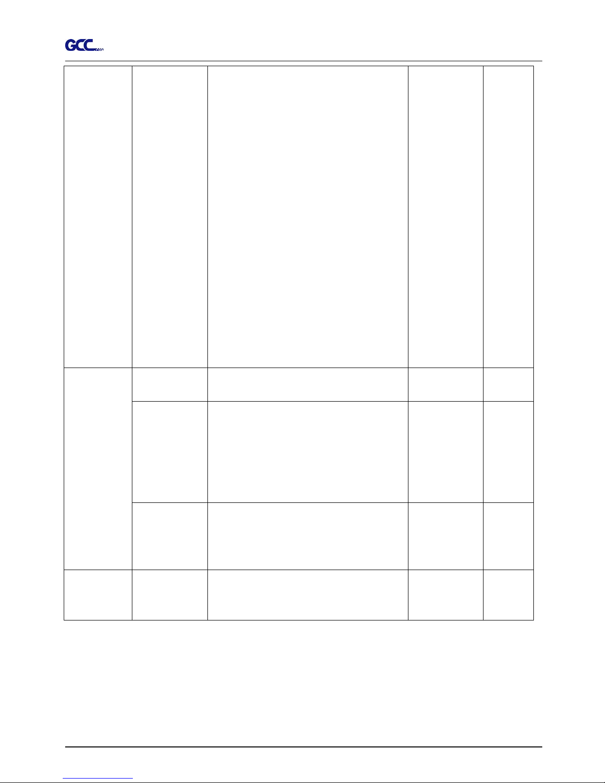
Press [MISC. KEY] will enable fine-tune
movement while moving tool carriage. Press
[MISC KEY] again can disable fine-tune
movement.
[Pause/Resume]
[PAUSE/RESUME] is to temporarily terminate
the operation of the machine. Press
[Pause/Resume] again will resume the cutting
job.
[ONLINE/OFFLINE]
[ONLINE/OFF LINE KEY] is to stop the cutting
job or aborts the change of the setting. Once
you pressed this key, the cutting job will be abort
immediately and can’t resume this job.
[Data Clear]
Clear the buffer memory.
A
uto Unrolled
Media
A
uto unrolled will unroll the media at least 50cm
when the next point of movement is located
beyond the unrolled position.
*If the length of the rolled media is less than 2
meters, or the rolled media is light, it is
recommend to set this as Disabled.
*Auto unroll is only effect on the roll/edge media.
*Using Single mode to size paper will disabled
this function
Media Back &
Forth
Enable this function can merge continues pen
up movement in order to prevent the movement
of media backward and forward. Especially, for
the SignPal Cutting Software (6.5v2 and 6.5v3)
user, you may notice that when you enable the
option “Advance After Plot”, after cutting job
finished, the media will move back to the origin
first, and then move to the end of the plot.
Enable this “Media Back & Forth” function will
directly advance the plot.
[Misc.]
Set Width Mode There are two width modes – “expanded mode”
and “unexpanded mode”. The cutting area of
expanded mode will increase about 20mm than
unexpanded mode.
Description of Operation 3-4
Page 34
Jaguar II User Manual
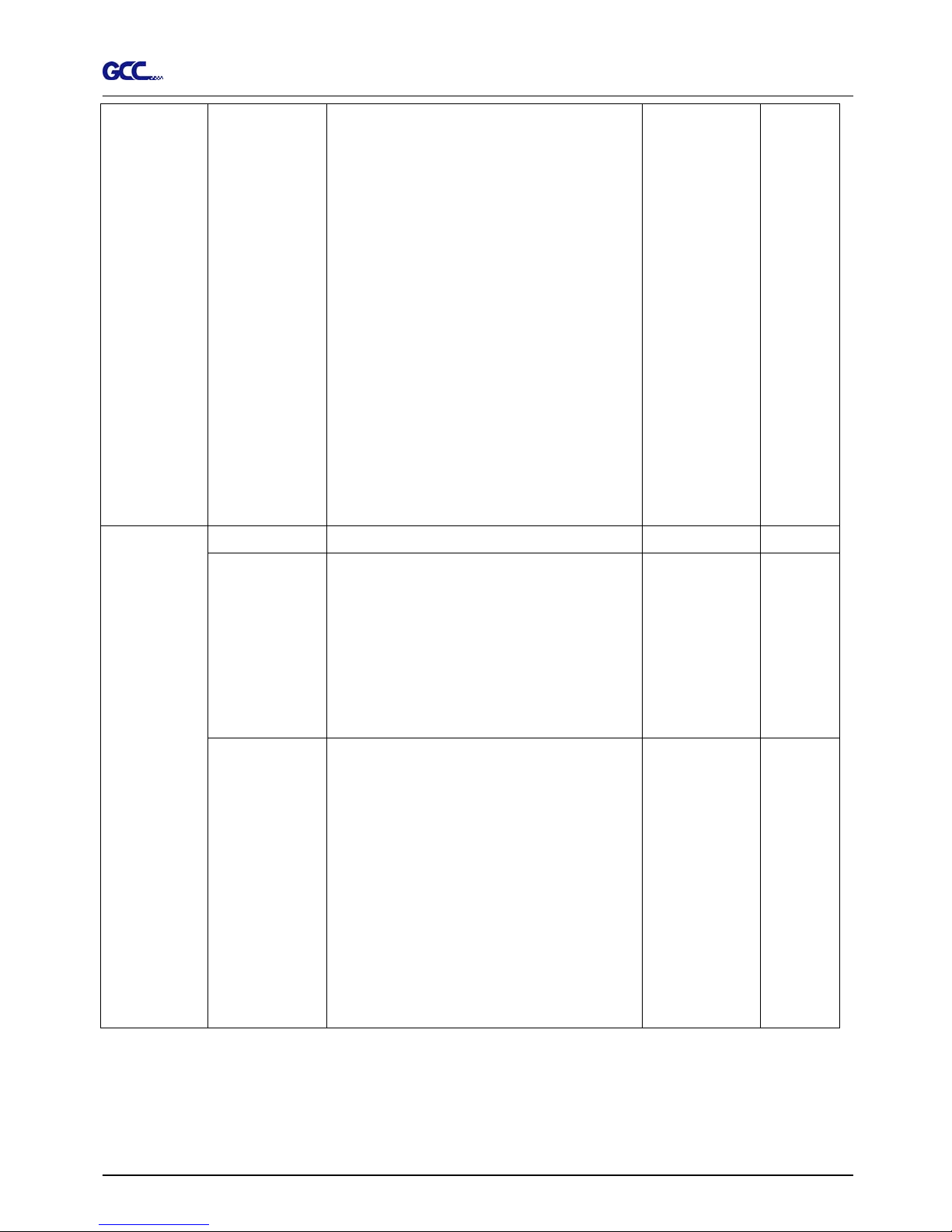
Set
Communication
These setting are used to connect the
communication between host computer and
cutter. Baud Rate is to determine the speed of
data transmission. Data Bits refers to the size
of one block of data and Parity is used to check
if data was revived correctly or not.
9600, n, 7, 1, p 9600pbs, 7 Bits with NO Parity
9600, o, 7, 1, p 9600pbs, 7 Bits with ODD Parity
9600, e, 7, 1, p 9600pbs, 7 Bits with EVEN Parity
9600, n, 8, 1, p 9600pbs, 8 Bits with NO Parity
9600, o, 8, 1, p 9600pbs, 8 Bits with ODD Parity
9600, e, 8, 1, p 9600pbs, 8 Bits with EVEN Parity
19200, n, 7, 1, p 19200pbs, 7 Bits with NO Parity
19200, o, 7, 1, p 19200pbs, 7 Bits with ODD Parity
19200, e, 7, 1, p 19200pbs, 7 Bits with EVEN Parity
19200, n, 8, 1, p 19200pbs, 8 Bits with NO Parity
19200, o, 8, 1, p 19200pbs, 8 Bits with ODD Parity
19200, e, 8, 1, p 19200pbs, 8 Bits with EVEN Parity
Firmware Version Display version number of Firmware and FPGA
code.
Paper Saving Mode
Enable this function will save media. There are
four alternatives in this function.
1. Length expanded mode
2. Width expanded mode
3. Both expanded mode
4. Both unexpanded mode
Both
unexpanded
mode
[Misc]
Select Language Provides LCM message display in different
languages. Jaguar II supports English, Spanish,
Italian, Deutsch, Japanese, Portuguese, Polish,
Turkish and French for LCM display.
English
Select Units Provides two unit systems for users convenient. Metric (cm/gram)
and English
(inch/oz)
Metric
Description of Operation 3-5
Page 35
Jaguar II User Manual
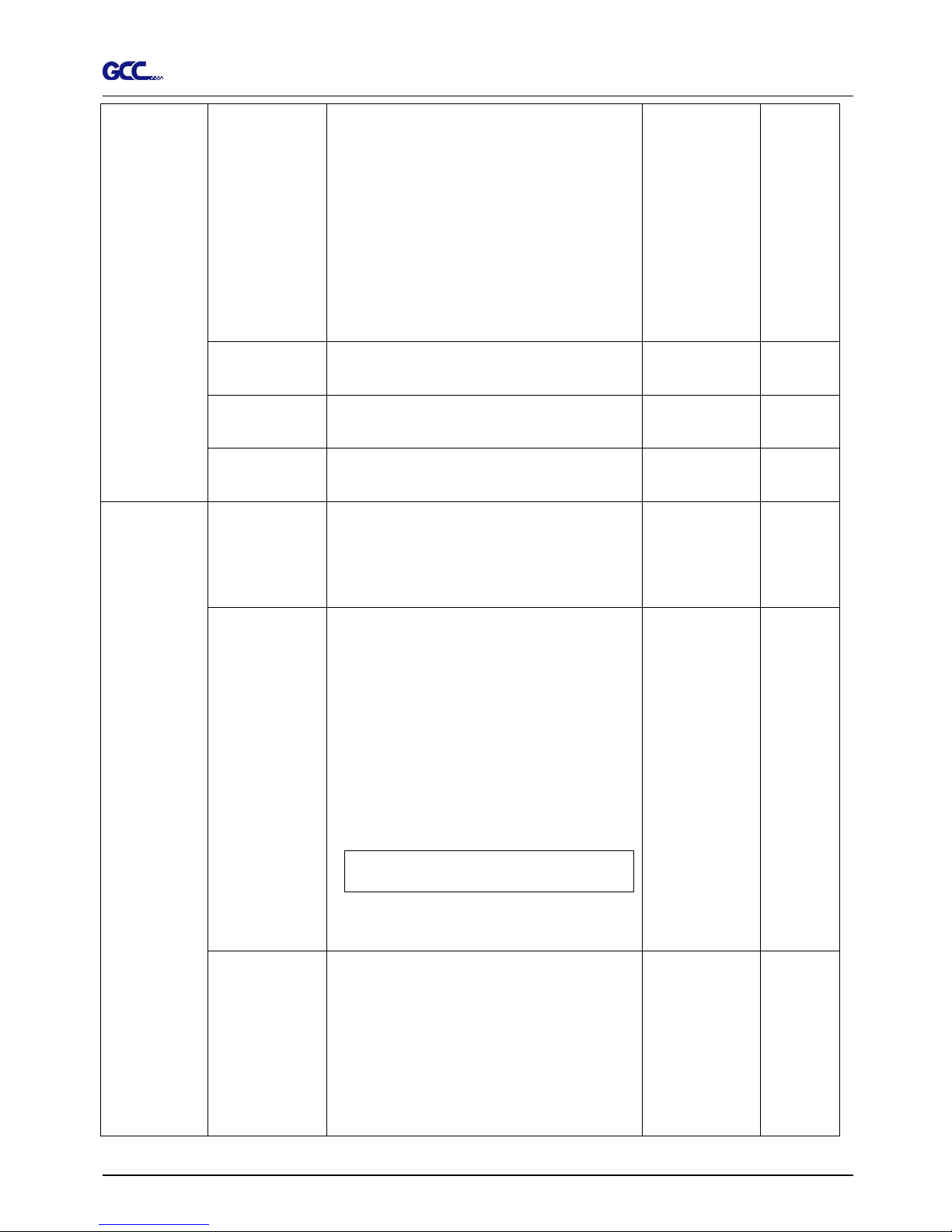
Scale Length &
Width
This “Scaling” feature is used to adjust the error
on the length and width, which may cause by the
thickness of the media. The Denominator is
the actual length, and the Numerator is the ideal
length measured from the resultant. For
example, cutting a line with 500.0 mm length.
The procedure as follows:
1. Press the [LEFT ARROW] to choose the
Numerator and select 500.0 mm,
2. Cut the length by sending a graph file,
3. Measure the length then use the [RIGHT
A
RROW] key to choose the Denominator
and,
4. Press [UP ARROW /DOWN ARROW]
changes the values to the actual length.
Set Smoothing Cut
Enable this feature to make curves smoother.
Set Tangential Mode
Provide the emulation tangential-cutting
technique with thicker media types and small
letter cuts.
Note: When the Offset value is setting at 0.000
mm Set Tangential Mode will automatically
setting at disable.
Disable
[Tool Select]
Pouncing It makes perforated paper patterns that used
together with a charcoal or chalk pounce bag.
The patterns will allow you to transfer an image
to surfaces for hand painting or cutting.
Place pouncing strip on the top of the cutting
pad to protect the cutting pad during.
Setting Range: 0 mm – 200 mm, for 0 mm is
used to disable the pouncing mode.
* Pouncing tool is an optional item.
Description of Operation 3-6
Page 36
Jaguar II User Manual
Set Panel Setup Setting to “Accept setup command”, the cutter
receives changes of set up commands from the
software when the machine is disabled.
Setting to “Control panel only”, the cutter will not
accept any set up command from the software,
the Force, Speed, Cutting Quality, and Offset
must directly changed from the Control Panel of
the cutter.
Save Parameter It can save 4 patterns of cutting parameters for
later use.
Save 1 to 4 Pattern 1
Over Cut It will cut an excess margin from the first and last
line segments.
0.00mm-1.00mm
0.05mm/step
0.00mm
Restore default It returns the settings values of the menu items
to factory-default values.
-
Square Cut This performs a cutting test at the present blade
position.
For more information, please refer to 2-7
adjusting the blade force and cutting speed.
Recut / Copy Allows user to repeat the last job without
sending the file again.
Setting Range:
For Recut: 1-99 with an increment of 1.
For Copy: 1-99 with an increment of 1.
It will leave 1mm between each copy.
Note: If the media is not large enough to
continuous copy, it will shows as following.
OpOtuSfa;ce #
iCfopoe isfn his ed
If both functions are selected at the same time,
the cutter only executes the last setting.
[Cut Test]
Mark Positions
(for contour
cutting)
This feature is making contour cutting on the
images that were generated by printers. The
registration marks should be printed along the
border of the image. Jaguar II provides two
alternatives.
1. 2-points registration contour cutting
2. 3-points registration contour cutting
Description of Operation 3-7
Page 37
Jaguar II User Manual
4. Making Connections
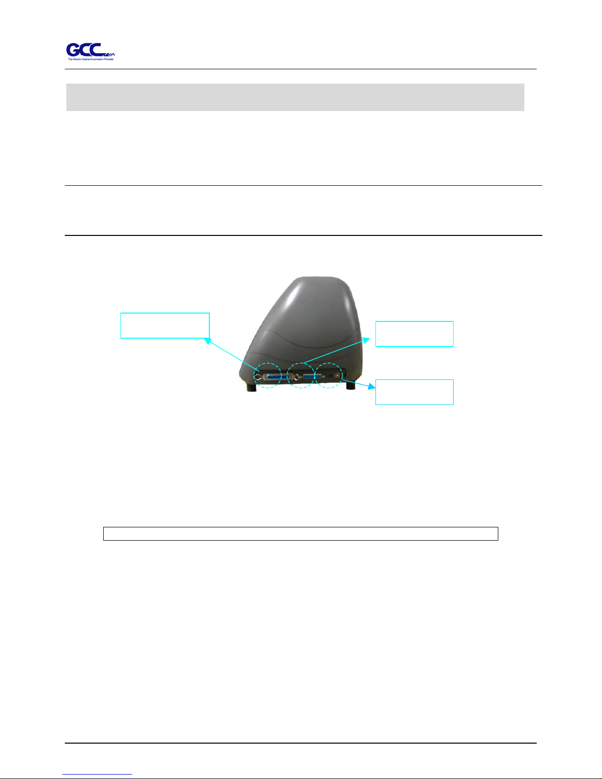
The cutting plotter communicates with a computer through a USB (Universal Serial Bus), Parallel port
(Centronics) or a Serial port (RS-232C). This chapter shows you how to connect the cutting plotter to a
host computer and how to set up the computer/cutting plotter interconnection.
!! Notice: When USB connection is enabled, both parallel port and serial port will be disabled
automatically.
USB port
Serial port
Parallel port
Figure 3-1
4.1 Universal serial bus
Puma II build-in USB interface are based on the Universal Serial Bus Specifications Revision
1.1. Operation system of Windows 95, Windows NT don’t support USB.
4.1.1 USB driver installation
Caution!! Don’t plug USB cable into Jaguar II before you install USB driver.
a. Put USB cable aside (don’t plug it into Jaguar II).
b. Insert “Installation CD”, and then click on “USB driver” to install USB driver. When it
shows “USB Driver installed”.
4.1.2 Connection
Plug the USB cable into the Jaguar II USB interface connector. Plug the other end of the cable
into the PC’s USB interface connector.
4.1.3 Cutting driver or sign cutting software installation
Insert “Installation CD”, and then click on “Driver” to install driver working with CorelDraw.
Connecting Cutting Plotters 4-1
Page 38

Jaguar II User Manual
4.2 PARALLEL TRANSMISSION
4.2.1 Connecting to the Parallel Port (Centronics)
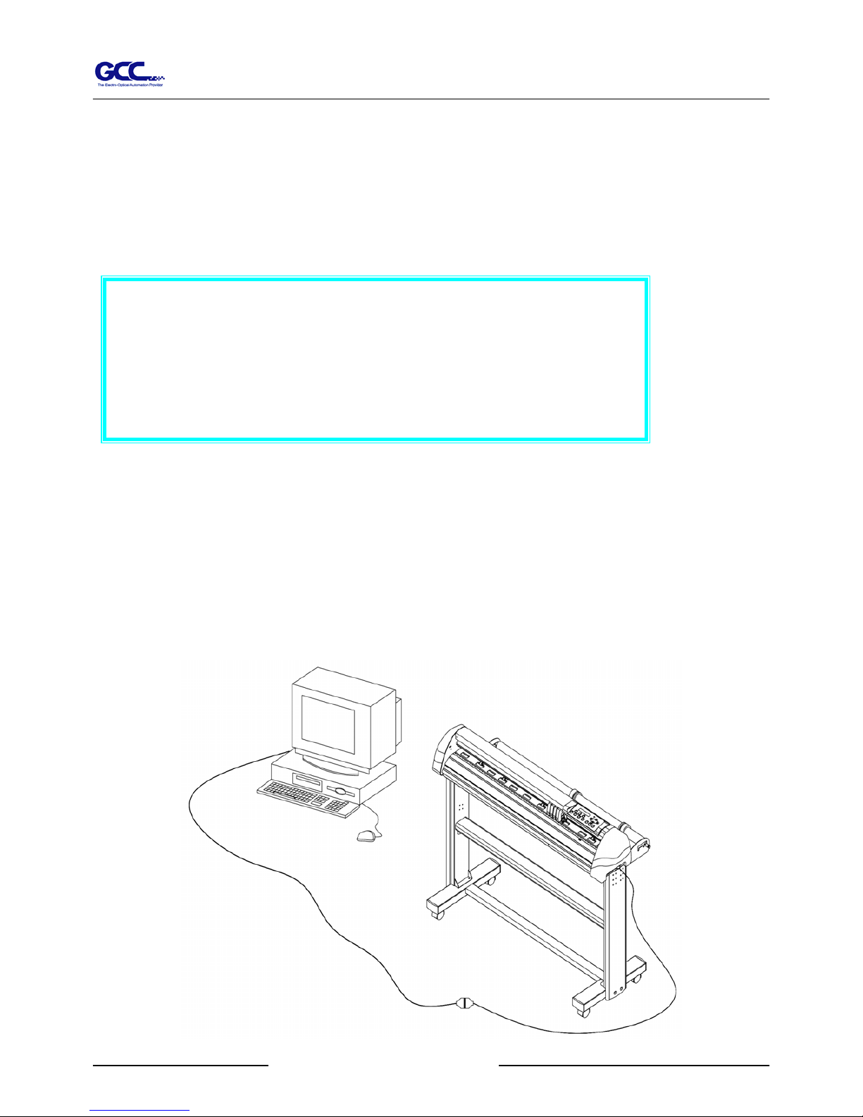
1. Connect a parallel cable to the cutting plotter and the host computer (Figure 4-1)
2. Set up the output port LPT1 or LPT2 from your software package
3. Send the data to your cutting plotter directly. Or, use DOS commands like TYPE or PRINT to
output data.
4.3 SERIAL TRANSMISSION
4.3.1 Connecting to the Serial Port (RS-232C)
1. For IBM PC, PS/2 users or compatibles, connect the RS-232C cable to the serial connector of the
assigned serial port (COM1 or COM2) of your host computer.
2. Set up the communication parameters (Baud Rate and Data Bits/Parity) to match the setting of
software package, refer to chapter 3 – “Misc” key description.
4.3.2 Transmitting the Data to Plotter
There are two options to transmit the data from the computer to the cutting plotter:
Option 1
With proper interface settings, the data can be transmitted from your application software package to the
cutting plotters directly.
Option 2
Most cutting software packages are able to emulate HP-GL or HP-GL/2 commands, therefore, Use DOS
commands like TYPE or PRINT to output your file. As long as the file is HP-GL or HP-GL/2 format,
the cutting plotter can output the data precisely.
For example, a file with PLT extension generated by SignPal can be transmitted directly to the plotter at
the DOS prompt, and then be cut out. Before outputting at the DOS prompt, set up a transmission
protocol between your cutting plotter and computer by a DOS command, MODE. Make sure that your
PC has the same communication protocol as the cutter. For example:
Connecting Cutting Plotters 4-2
Page 39
Jaguar II User Manual
MODE COM2: 9600, N, 8, 1, P
Then, use TYPE command to output via COM2 if COM2 is the assigned output port.
TYPE filename > COM2
Tip:
Add the MODE command line to your system’s AUTOEXEC.BAT to
automatically execute MODE command every time you want to output
your data at the DOS prompt via serial connection. However, values in
a MODE command should comply with the related requirements of you
r
software. Refer to DOS manual for further information.
4.4 Interface of Macintosh Computer
In order to operate the cutting plotter with a Macintosh computer (e.g. Power Mac), you need a MAC
modem cable (DIN 8 to DB25) to connect the RS-232C cable, please refer to Fig 4-2.
The cable is an optional item, which could be ordered through your dealer.
Connecting Cutting Plotters 4-3
Figure 4-2
Page 40

Jaguar II User Manual
5. Maintenance
This chapter explains the basic maintenance (i.e. cleaning the cutting plotter) required for the
cutting plotter. Except for the below mentioned, all other maintenance must be performed by a
qualified service technician.
5.1 Cleaning the Cutting Plotter
In order to keep the cutting plotter under good condition and best performance, you need to
clean the machine properly and regularly.
Cleaning Precaution !
Unplug the cutting plotter before cleaning in
order to prevent electrical shock.
Never use solvents, abrasive cleaners or strong
detergents for cleaning. They may damage the
surface of the cutting plotter and the moving
parts.
Recommended Methods:
Gently wipe the cutting plotter surface with a lint-free cloth. If necessary, clean with a
damp cloth or an alcohol-immersed cloth. Wipe with water to rinse off any residue and dry
with a soft, lint-free cloth.
Wipe all dust and dirt from the tool carriage rails.
Use a vacuum cleaner to empty any accumulated dirt and media residue beneath the pinch
roller housing.
Clean the platen, paper sensors and pinch rollers with a damp cloth or an alcohol-immersed
cloth, and dry with a soft, lint-free cloth.
Wipe dust and dirt from the stand.
Basic Maintenance 5-1
Page 41
Jaguar II User Manual
5.2 Cleaning the Grid Drum
1. Turn off the cutting plotter, and move the tool carriage away from the area needed to be
cleaned.
2. Raise the pinch rollers and move them away from the grid drum for cleaning.
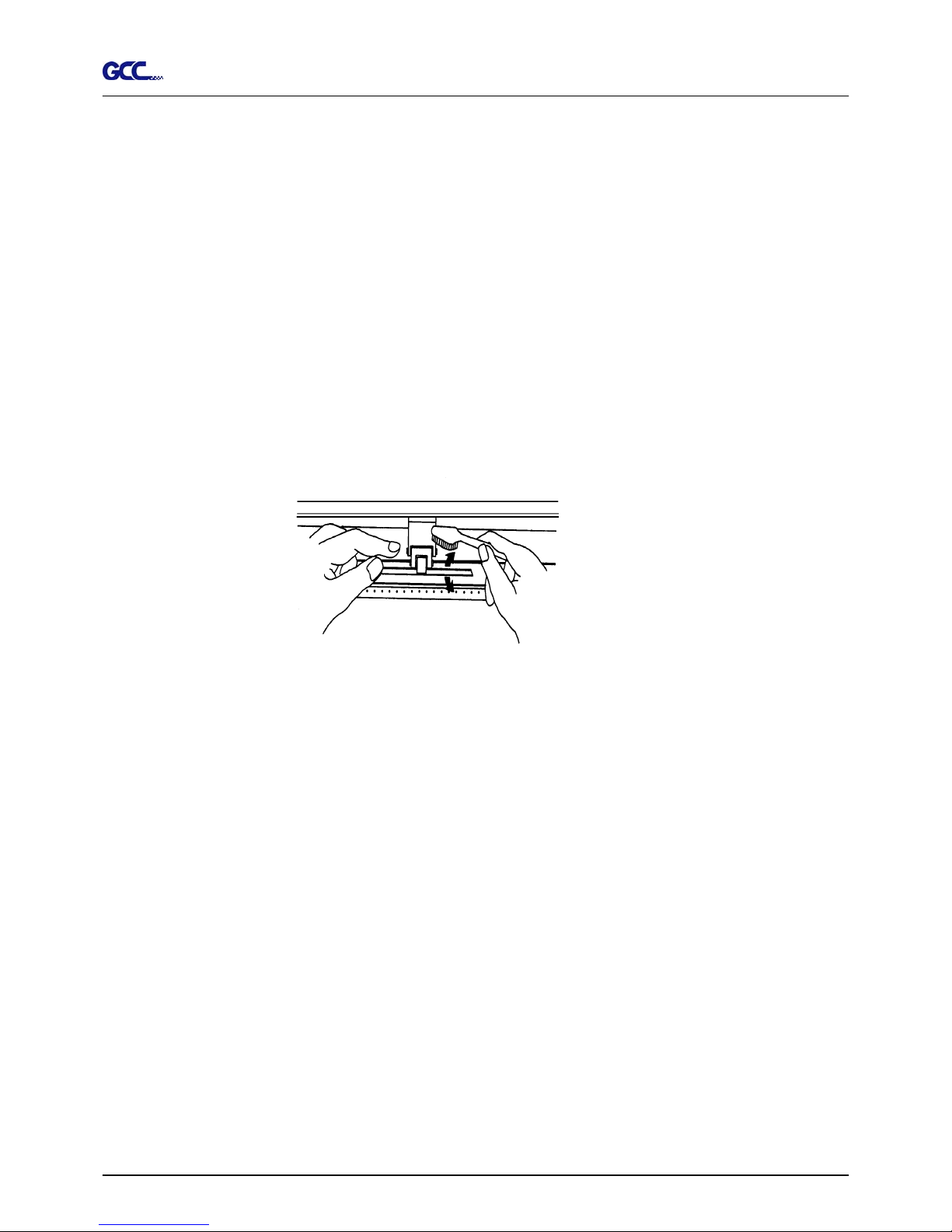
3. Use a bristle brush (a toothbrush is acceptable) to remove dust from the drum surface.
Rotate the drum manually while cleaning. Refer to Figure 5-1
Figure 5-1
5.3 Cleaning the Pinch Rollers
1. If the pinch rollers need a thorough cleaning, use a lint-free cloth or cotton swab to wipe
away the accumulated dust from the rubber portion of the pinch rollers. To prevent the pinch
rollers from rotating while cleaning, use finger to hold the pinch rollers not to rotate.
2. If needed to remove the embedded or persistent dust, use the lint-free cloth or cotton swab
moistened with rubbing alcohol.
Basic Maintenance 5-2
Page 42
Jaguar II User Manual
Troubleshooting 6-1
This chapter helps you to correct some common problem you may come across. Prior to getting
into the details of this chapter, please be sure that your application environment is compatible
with the cutting plotter.
Possible Causes:
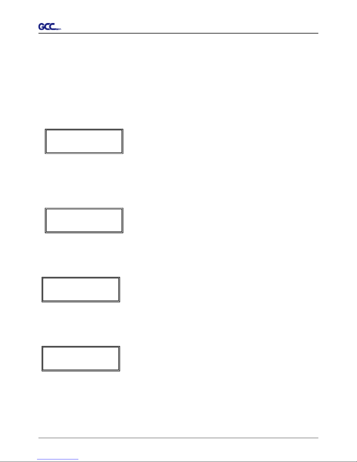
6.1 Non-Operational Problems
Check the following first:
! Does the AC power cord plug in properly?
! Does the AC power cord connected to the power connector properly?
! Does the power LED still illuminate?
Solutions:
If the LCM is able to display the message, the cutting plotter should be in a normal
condition. Switch off the cutting plotter and turn it on again to see is the problem still
existing.
If the LCM is not able to display any message, contact the technician from your dealer.
Note:
Before having your cutting plotter serviced, please make
certain that the malfunction is in your cutting plotter, not
the result of an interface problem or a malfunction in you
r
computer or a software problem.
Why is the cutting plotter not functioning?
6. Trouble Shooting
Page 43
Jaguar II User Manual
Troubleshooting 6-2
6.2 Operational Problems
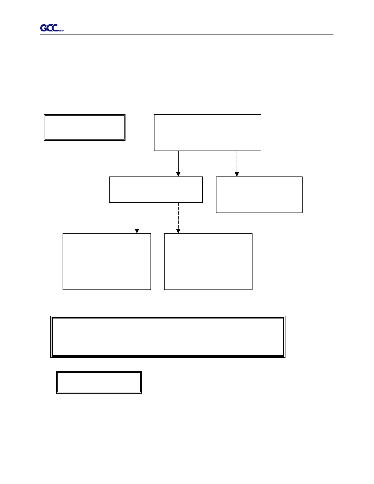
Some mechanical problems or failure during operation will cause some problems. The error
messages shown on the LCM present the problem first, and followed by recommended actions.
If the problem still exists after the recommended actions have been done, have your cutting
plotter serviced.
Error, Check Media
Or Drum or X Motor
This message indicates that there might be
a
problem on the X axis. Check if the drum is
working well and if the media is well loaded.
Correct the problem and re-power on to reboo
t
system.
Error, Check Media
Or Y Motor
This message indicates that there might be an
obstruction to carriage relating to a problem o
n
the Y axis. Correct the problem and r e-power on
to reboot system
.
Error, Check Carriage
Sensor or VC Motor
This message indicates that the blade up/dow
n
sensor malfunction. Re-power on to re-boo
t
system. If the problem still exists, find
a
serviceman.
Graph Was Clipped.
Data In Buffer
This message indicates that the cutting exceeds
the cutting limit. Reload larger media or re-scale
the plot to a smaller size; then press the ke
y
followed by the display of LCM to continue.
Page 44
Jaguar II User Manual
6.3 Cutting Plotter/Computer Communication Problems
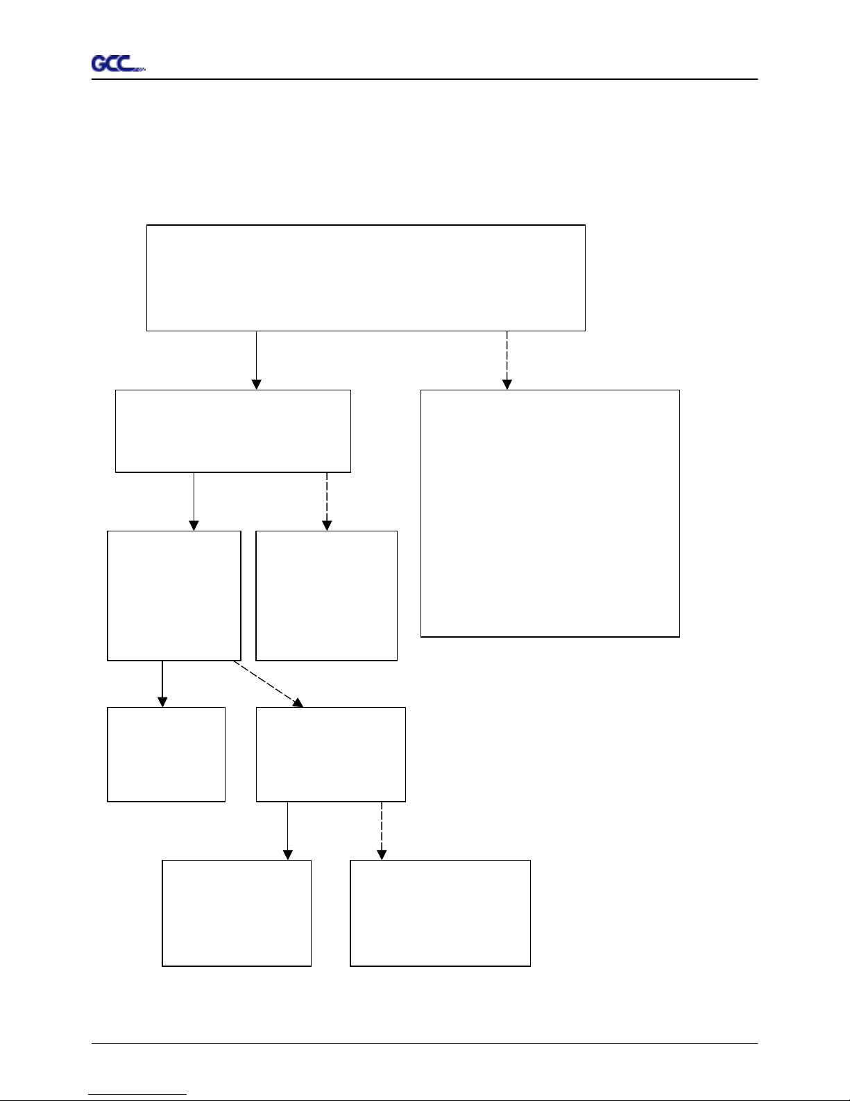
The messages showed below present problems in relation to cutting plotter/computer
communication.
Communication Error
Setup: MISC. key
Yes N o
Has the interface setting been
done correctly?
Refer to Chapter 4 -
Connecting your cutting
p
lotter.
Yes
Try the communication
between your cutting plotter
and computer. If it still does
not work, have your cutting
p
lotter serviced.
N o
Refer to the “MISC” key in
Chapter 3 - Description of
Operation for the port setup.
Is the connection cable connected
to the cutting plotter and computer
p
roperly?
Note:
The computer also needs to set up compatible communication parameters to the
cutting plotter set up.
If your cutting plotter can not recognize the
HP-GL/2 or HP-GL commands, please chec
k
the HP-GL/2 or HP-GL commands applied to
your cutting plotter are used properly.
HP-GL/2 Cmd. Error
Troubleshooting 6-3
Page 45
Jaguar II User Manual
Troubleshooting 6-4
6.4 Softw are Problems
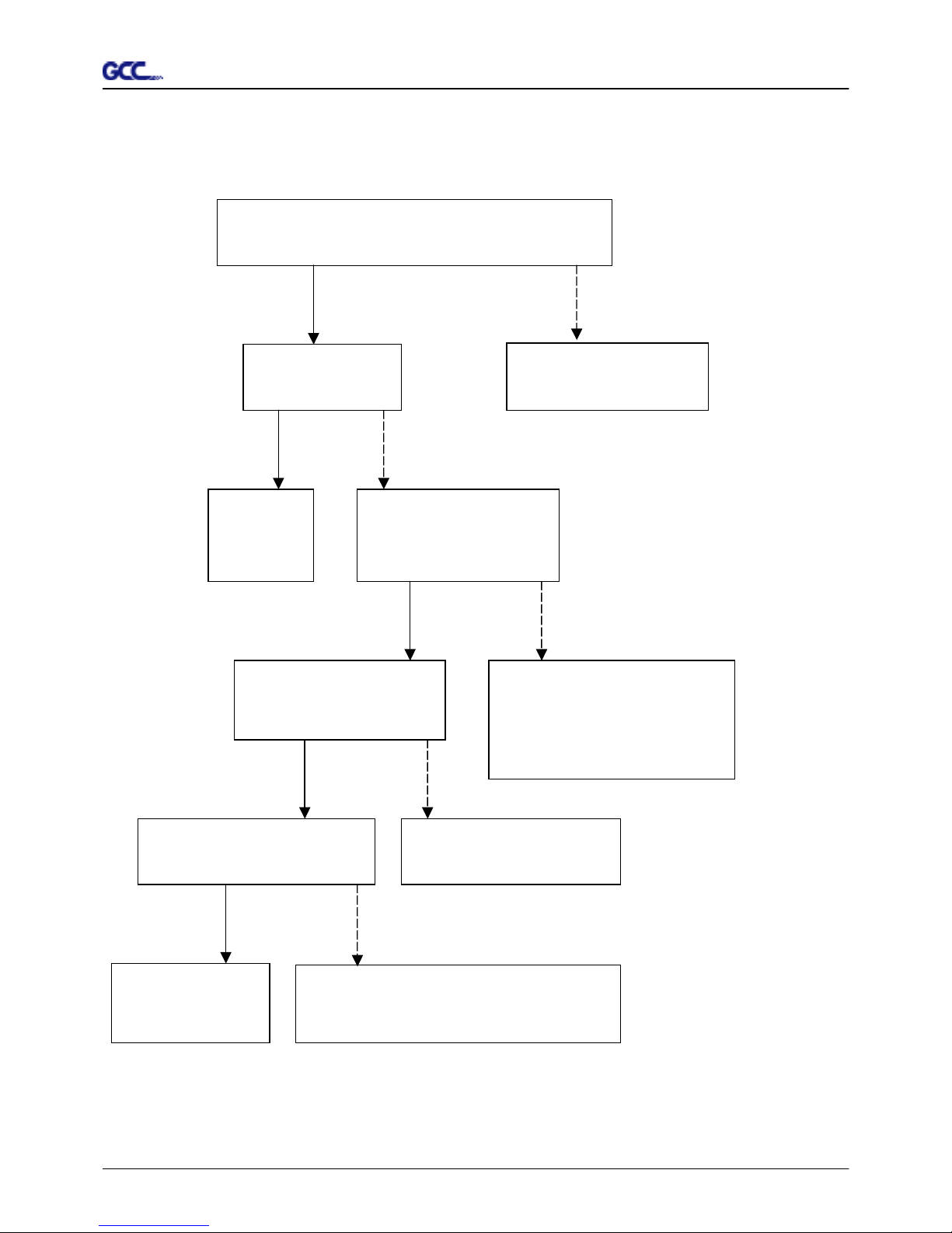
Check the following first:
Does your software package indicate that it will work with you
r
computer and cutting plotter?
Does your software support HP-GL and HP-GL/2 drivers?
(* check the configuration settings of your software.)
Yes
No
Does the cutting plotter interface
match the requirements of your
software?
Does your
software
recommend using
a different cable?
Does the software
vendor provide a
sample file?
Most well known cutting softwares in
the world have drivers for our cutting
p
lotters. If not, use software that has
HP-GL and HP-GL/2 emulatio
n
supports and you can chose the
following three drivers:
#
A3 size: HP7475A
#
A1 size: HP7580A
#
A0 size: HP Draf Pro Exl or HP
Draf Master
Yes
No
Refer to Chapter 4,
connecting your
cutting plotter.
Yes
No
Try using the
recommended
cable.
Yes No
Re-power on the
cutting plotter and
try to send the file
again.
Do something about the
error message display on
LCM, or consult your
software vendor.
Page 46
Jaguar II User Manual
Troubleshooting 6-5
6.5 Cutting Quality Problems
Is the blade installed correctly and the blade holder
fastened securely?
Yes
No
Is the blade dull or
chipped?
Yes No
Replace
with a new
blade
Is tool force set up
properly? (The default
for tool force is 80 gf)
Yes No
Adjust the tool force to obtain
an optimum blade force. Refer
to chapter 3 “FORCE” and
“CUTTING TEST”
Is the tool offset set up
properly?
Yes No
Adjust the tool offset to
obtain an optimum value.
Is there any dirt adhered to the
blade?
Yes No
Remove the blade
and clean it.
Please contact your dealer for technician
support.
Refer to Chapter 2.3
“ Blade Installation”.
Page 47
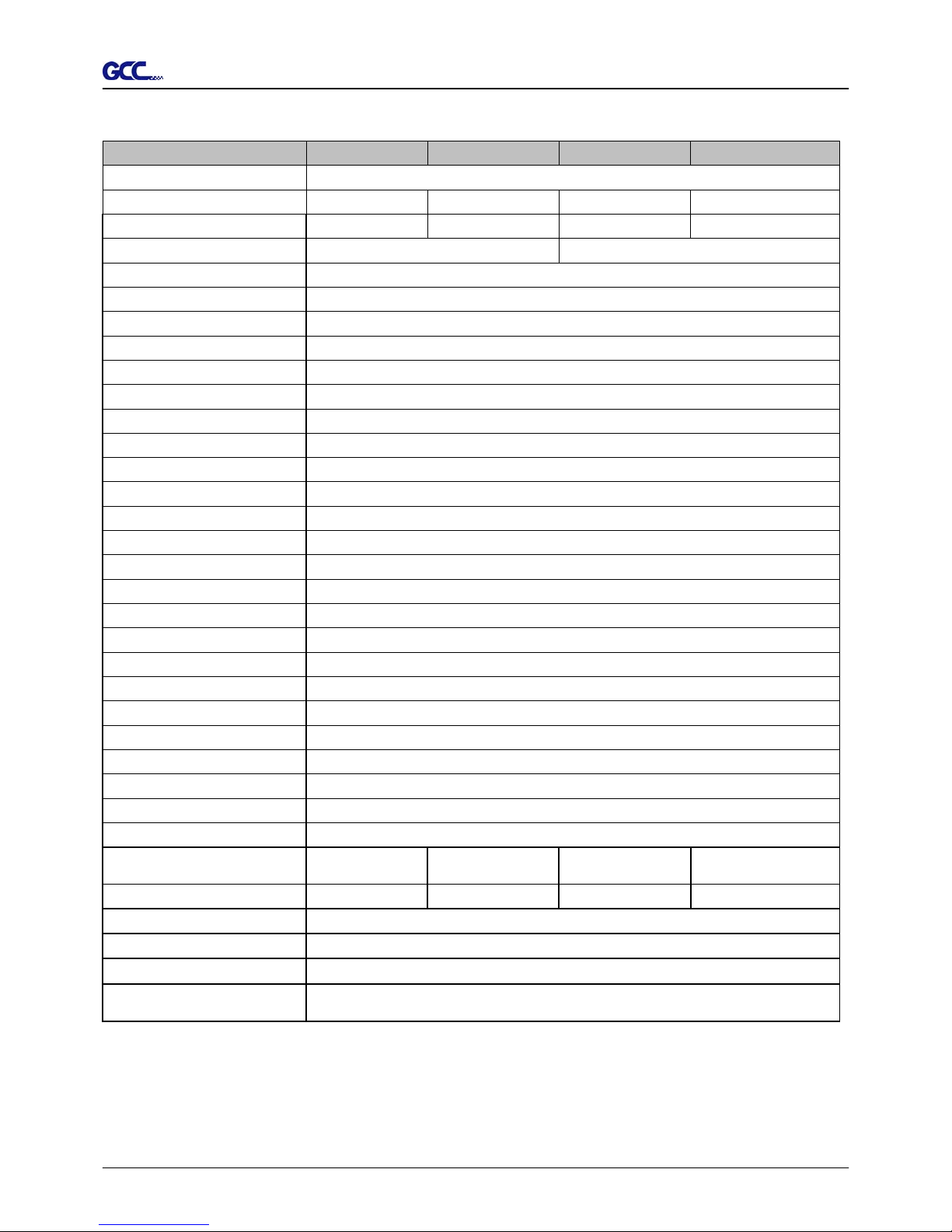
Jaguar II User Manual
Jaguar II Specifications
Model : Jaguar JII-61 JII-76S JII-101S JII-132S
Operational Method Roller-Type
Max. Cutting Width 610mm (24.0in) 760mm (29.9in) 1016mm (40in) 1320mm (52in)
Max. Media Loading Width 770mm (30.3in) 920mm (36.2in) 1270mm(50in) 1594mm(62.8in)
Number of Pinch Rollers 3 4
Min. Media Loading Width 50mm
Acceptable Material Thickness 0.8mm (0.04in)
Drive DC Servo Control
Cutting Force 0~600 g
Max. Cutting Speed 1530 mm/sec (60ips, Diagonal)
Tangential- emulation Yes
Paper Cutting Ability Yes
Sliter Groove & Tool Yes
Media Basket Optional
Acceleration 4.2 G (gravity)
Offset 0~1.0 mm (with an increase of 0.025mm)
Mechanical Resolution 0.00625mm
Software Resolution 0.025 mm
Repeatability 0.1mm
Buffer Size 4 MB
Interfaces USB, Parallel and Serial (RS-232C)
Commands HP-GL, HP-GL/2
Configurable Origin Yes
Curve & Arc Smoothing Yes
Test Cut capability Yes
Replot Function Yes
Copy Function Yes
Pouncing Function Yes
Control Panel LCM (20 digits x 2 lines), 14 Keys, 1 Power LED
Dimension (HxWxD) mm
(HxWxD) in
414 x 930 x 490
16.3 x 36.6 x19.2
1166 x 1080 x 667
45.9 x 42.5 x 26.3
1166 x 1430 x 667
45.9 x 56.0 x 26.3
1166 x 1754 x 667
45.9 x 69.1 x 26.3
Net Weight (kg) 37.2kg 40.5kg 53.3kg 61.0kg
Power Supply AC 100~240V (auto switch)
Power Consumption Max. 110watts
Environment Humidity 30% ~ 70% relative humidity (operating)
Environment Temperature
0°C~55°C / 32°F~131°F(operating)
-40°C~75°C / -40°F~167°F(storage)
The above specification is subject to change without prior notice.
Stand for Jaguar JII-61 is optional.
Specifications
 Loading...