

Page 1 GCR Class 8B
Page 1 GCR Class 8B
Great Central Models
Robinson GCR Class 8B Atlantic
(LNER C4)
Version 1.2 February 2013
Assembly Instructions Revised July 2014
Catalogue #GCM005
This kit is optimised for P4 and EM standards. The kit was designed by “Great Central Models” as part of an
expanding range of Great Central Railway locomotives.
Great Central Models Ltd is registered as a Private Limited Company - 7355519
Further details - www.greatcentralmodels.co.uk
Enquiries to sales@greatcentralmodels.co.uk or via the contacts page on the web site
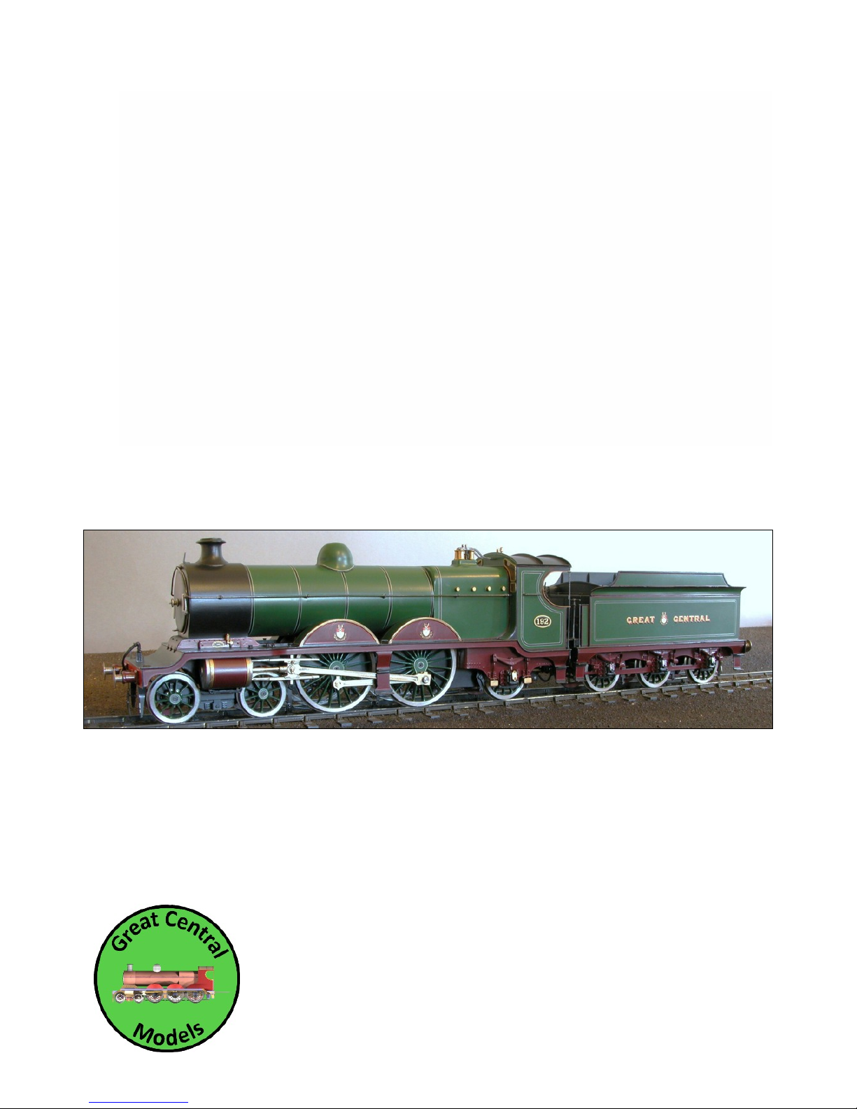
The picture above is for illustration only, it is actually a 7 mm model painted and finished by a very well known artist, whose
writings on the subject are well worth reading. Also worthy of note is the newly released book by John Quick, “Robinson’s
Locomotive Liveries on the Great Central Railway”.

Page 2 GCR Class 8B
Page 2 GCR Class 8B
Robinson GCR Class 8B LNER C4
The Class 8B was a trial build of a 4-4-2 soon after Robinson decided on a big engine policy. While impressed by the work done
by Churchward at Swindon, he seems to have adopted a cautious approach so decided to build 4 locomotives, essentially with
all the major features the same, but the Class 8C as a 4-6-0 and the Class 8B as a 4-4-2 Atlantic. 6’ 9” coupled wheels were fitted.
The work was done by Beyer Peacock and was based on the earlier 4-6-0s, the so-called “fish” engines which were Class 8 under
the Great Central way of categorising locomotives.
In principle, the rear end of the Class 8B was designed so that it could be converted easily to the Class 8C but it was the ‘Atlantic’
design that prevailed.
All were built between 1903 and 1906 by Beyer-Peacock (7), North British Loco. Co. (12), and at Gorton (8) with saturated steam
boilers. The only difference was really the fire grate, in the first build it was rather shallow, matching the Class 8C. Once the
decision had been made to stick with the 8B design rather than the 8C, a deeper fire box was fitted. They were withdrawn over
a period from 1939 until 1950, having been replaced by the B17s, but mainly during 1948-1950. None of them received BR
numbers, their replacement meant that none were re-painted or re-numbered.
Superheating was started in 1912 and continued right up to 1936 - no rush then!
As with the other Robinson locomotives, chimneys were a varying feature. The classical GCR chimneys were not approved by the
LNER because of the loading gauge issues (in common with most of the GCR classes) so were replaced initially by the LNER
flower-pot version. Later a pseudo-GCR chimney was fitted. Use the “13 ft Gauge” column below as a guide to when this
happened, generally it was a lot later than other Robinson classes. Flattened or angular domes were used at various times, the
angular domes seemed to appear during WW 2. The movement of the whistle from the cab top onto the boiler happened for
the same reasons of loading gauge As always, a good picture is the best guide, provided the dating is accurate!
For guidance, according to RCTS data and Yeadon Vol 13:-
Manufacturer Built Withdrawn GCR # Superheated LNER 1924 LNER 1946 13 ft Gauge
Beyer, Peacock 12/1903 11/1950 192 9/1920 5192 (10/1925) 2900 (8/1946) 5/1937
Beyer, Peacock 12/1903 11/1950 194 10/1925 5194 (10/1925) 2901 (6/1946) 1/1938
Beyer, Peacock 7/1904 4/1949 263 6/1926 5263 (4/1924) 2902 (6/1946) 8/1938
Beyer, Peacock 7/1904 6/1949 264 7/1921 5264 (2/1924) 2903 (9/1946) 9/1937
Beyer, Peacock 7/1904 12/1947 265 9/1920 5265 (1/1925) 2904 (8/1946) 5/1937
Beyer, Peacock 7/1904 10/1943 266 5/1921 5266 (5/1922) 2905 5/1938
Beyer, Peacock 7/1904 11/1947 267 9/1920 5267 (2/1925) 2906 (3/1946) 3/1939
N.B. Loco. Co 10/1905 12/1947 1083 1/1921 6083 (9/1924) 2907 (6/1946) 4/1937
N.B. Loco. Co 10/1905 11/1950 1084 8/1929 6084 (7/1925) 2908 (6/1946) 7/1937
N.B. Loco. Co 10/1905 11/1950 1085 1/1925 6085 (1/1925) 2909 (6/1946) 1/1925
N.B. Loco. Co 10/1905 2/1949 1086 8/1914 6086 (2/1924) 2910 (6/1946) 10/1937
N.B. Loco. Co 10/1905 11/1944 1087 9/1920 6087 (12/1925) 2911 11/1937
N.B. Loco. Co 10/1905 8/1949 1088 12/1926 6088 (11/1924) 2912 (9/1946) 12/1936
N.B. Loco. Co 11/1905 4/1947 1089 6/1920 6089 (10/1924) 2913 (11/1946) 10/1937
N.B. Loco. Co 11/1905 11/1939 1090 3/1914 6090 (10/1924) 8/1936
N.B. Loco. Co 11/1905 3/1948 1091 4/1925 6091 (4/1925) 2914 (6/1946) 9/1937
N.B. Loco. Co 11/1905 6/1949 1092 3/1921 6092 (7/1925) 2915 (10/1946) 8/1936
N.B. Loco. Co 11/1905 11/1948 1093 11/1927 6093 (9/1925) 2916 (9/1946) 6/1937
N.B. Loco. Co 11/1905 5/1949 1094 1/1936 6094 (2/1924) 2917 (8/1946) 7/1937
Gorton 2/1906 12/1950 260 2/1935 5260 (12/1925) 2918 (8/1946) 5/1938
Gorton 3/1906 11/1950 261 1/1927 5261 (12/1925) 2919 (8/1946) 2/1937
Gorton 4/1906 2/1948 262 4/1925 5262 (12/1925) 2920 (8/1946) 1/1937
Gorton 5/1906 4/1948 358 5/1920 5358 (12/1925) 2921 (8/1946) 3/1937
Gorton 6/1906 6/1948 360 10/1920 5360 (12/1925) 2922 (8/1946) 12/1936
Gorton 7/1906 2/1949 361 3/1912 5361 (12/1925) 2923 (8/1946) 10/1937
Gorton 6/1906 1/1948 362 3/1928 5362 (12/1925) 2924 (8/1946) 3/1937
Gorton 8/1906 4/1949 363 2/1921 5363 (12/1925) 2925 (8/1946) 2/1937

Page 3 GCR Class 8B
Page 3 GCR Class 8B
Additional Notes
LNER Numbering - there were huge variations in how LNER numbering was applied. Sizes varied, location carried, style varied,
sometimes just ‘NE’, sometimes still with the GCR cab side plate and the letter ‘c’ added to the LNER number, sometimes on the
tender but mainly on the cab once the LNER got themselves sorted out.
Photographs should be consulted when deciding what number to have. Of course in GCR days it was all rather simpler.
Locomotives could have a carriage heater connection at the front as they became used on passenger trips which would mean
that a heating pipe should also be added to the tender.
Smoke box handles - for this class the wheel arrangement was kept throughout their lifetime.
There are more versions of the chimneys and domes than catered for by the kit. The original chimney was of a much finer
appearance and rapidly failed in service.
Ramsbottom 2 column valves were originally fitted and a branching arrangement used for the traditional 4-column appearance.
These were originally uncased but casing was added later. Ross valves replaced the Ramsbottom valves during superheating.
Tail rods on the cylinders were removed before grouping but I have no dates for this, it seemed to happen over a longer period
than other GCR classes, but before grouping. On super-heating a ‘snifting’ valve was fitted behind the chimney. At the same
time the ash ejector was fitted on the right of the Smoke Box.
Centre steps were removed before the grouping, at speed they could ‘whip’ and potentially hit the connecting rod.
Livery was perplexing. Originally in full GCR green regalia, they soon reverted to lined black and then the LNER painted them
green again until WW 2, when they all became black again. Under LNER management, the beading was always unpainted and
usually unpolished.
Tenders when built for 192, 194 were the GCR 3,250 gallon version but these were soon replaced by the group standard with
plated sides.
As with all models from this era, the best thing a modeller can do is refer to published literature such as
Ÿ “Locomotives of the LNER Part 3A” from RCTS
Ÿ “Locomotives of the Great Central Railway” by E. M. Johnson
Ÿ Photographs from various collections - usually available at shows such as Scaleforum and Scalefour North
Ÿ “Yeadon’s Register of LNER Locomotives - Part 13”
These locomotives, known as the “Jersey Lilies” ranged far and wide and could be seen as far away from GCR rails as Plymouth
and Weston-Super-Mare, even running a slip coach at one stage. They ended their days doing light duties on the BR Eastern
Region. Their visits to Plymouth are a good excuse to put a “Green, with rivets”, next to a GCR Class 8B, “Green, without rivets”
Important Note
This kit has been designed for P4 or EM standards. Alternative parts have been designed into the brass and nickel silver frets.
There are plenty of spare parts for the smaller items. Considerable additional work will be needed to build this kit to ‘00’
standards. Remember that ‘00’ and EM wheels will cut into the boiler space. For EM modellers care must be taken not to
increase the upward movement of the wheels if sprung or compensated by filing out the axle slots in the frames. If the kit, when
built, has a lot of side play then even the P4 version will find the wheels hitting the boiler. In all cases the boiler can be ground
out to clear this.
Notes on the kits and constituent parts
The etched parts in this kit have been designed using a CAD program (TurboCAD 18.2) to ensure accuracy when fitting the parts
together. Included in these notes are:-
Ÿ A list of etched and cast parts
Ÿ A list of additional and optional parts
Ÿ Drawings of the etch fret

Page 4 GCR Class 8B
Page 4 GCR Class 8B
Ÿ Detailed step-by-step instructions with the drawings extracted from the CAD originals
The original CAD drawings were prepared from GA drawings obtained from MOSI in Manchester and scaled at 12” to 1’. During
the design process a number of compromises had to be made (such as the frame widths) because of the materials and parts
available to the modeller and the P4 and EM standards. These compromises were used to draw a full size CAD drawing which
was then used to provide the instructions and construction drawings and the final etch parts. The etch parts of the drawing
were scaled down very accurately to produce etches for the 4 mm modeller.
The kit prototypes were built by the designer. The first trial etch was used as a feasibility project and to write outline
instructions. The second test etch was used to test the assembly, write instructions and produce the assembly diagrams as well
as a viable model. A modeller familiar with etch brass kit construction should be able to build an accurate model if these
instructions are followed, generally as written. However, fine-scale modellers being who we are, other ways of building the kit
will be tried!
The Instructions
More years ago than I care to remember I was involved in validating and writing Master Work Sheets for the Royal Air Force.
These were sets of instructions that had to be followed to the letter by technicians world-wide even though they may never
have met that particular piece of equipment before. Deviations were never permitted to the technicians – given that the
machines being tested were vital to safe flying – and any permission to be deviant granted by senior authority was subject to a
very close monitoring process.
However, senility and pending obsolescence have taken their toll – nobody is perfect – so if you find anything in these
instructions you feel to be wrong it will be examined closely and amended where appropriate. Likewise, with the measurements
of the parts, if there is something which you feel may be wrong then, please let me know. It would be nice if this was supported
by drawings, or copies of drawings with time stamps if possible. Photographs are useful as well. But be warned, the available
drawings are neither consistent nor accurate if my research means anything at all and there were so many cosmetic changes
made to these locomotives over nearly 50 years that photographs without a date stamp must be treated with some caution.
Things to note
In a few areas there are alternative ways of doing things. While there are traditional etched springs on Sheet 3, for this kit the
centre springs have been printed using 3D CAD technology. They are fitted to the horn blocks. Note that these are heat sensitive
and will melt as quickly as white metal castings. The etched or printed springs mean that the wheels can also be removed for
‘servicing’.
Continuous Springy Beams (CSBs) may be fitted - they seem to be all the vogue these days. I am a little uncomfortable with the
idea for a complex wheelbase such as a 4-4-2 and prefer to stick with the prototype idea where each axle is sprung by itself.
Short handrail knobs are used for the spring mounts. EM and ‘00’ modellers may use frame blanks to remove the need for
springing.
Stephenson’s Valve Gear would have been visible only by looking very carefully, for this engine. Extra parts are provided so you
can experiment with the way it fits together. If you are tempted to try this then please do remember not to solder the parts in
situ ‘after’ you have fitted your plastic centred wheels. The valve gear may be fitted in working order or as a very loose fit on the
centre axle. In the second case they will be visible but will not move except around the axis of the axle.
The Stephenson’s Valve Gear is tricky to get working well and may be left out. The rest of the engine will still look good when
finished and painted.
The builder will find an array of brake parts on the fret. While 3D brakes are an option and remove the possibility of shorts while
fitting closely to the wheels, they are vulnerable to handling errors. However, there are ways to strengthen them with the etch
base parts, or the builder may use etch parts only.
Rear and centre frame spacers - those supplied on the etch are to scale and may be fitted if desired - you can create frame
spacers which are a good representation of the originals with their strengthening brackets but these are difficult to see when
the model is completed. In practice the rear spacer construction was used to steady the front of the fire box but this may be
omitted without weakening the whole chassis. P4 and EM versions of these spacers are supplied together with some generic
spares. These are not standard widths though. Use the spares in appropriate places if you do not need the scale spacers or wish
to add your own parts for additional electrical pick-up.
There is substantial current collection capability in the tender. I was persuaded not to have pick-ups in the locomotive since they
would detract from the scale frame spacers and the valve gear and since there is plenty of space in the tender with or without
the optional DCC chip this may be a good option. The two wires for the motor may then represent the vacuum and heating
pipes.

Page 5 GCR Class 8B
Page 5 GCR Class 8B
The part numbers and descriptions (where space permits) are half etched on the frets as near to the parts as sensible and match
the description that appears in the Parts List. These annotations will appear in the form “212”, or “223,224” or 213-217” or 218225+3”. Where something like “212EM” appears on the fret then that is the EM version of a part that will also have a P4
(unlabelled) part on the fret. Where the “+” appears in the part number it shows that additional parts have been included and
the number following shows that 3 additional parts are on the fret. This allows for two possibilities
a) losing very small parts in the carpet after cutting them from the fret
b) practising the assembly in cases where some difficulty may be expected
Also on the fret there are a couple of blocks on which to practice your skill at pushing out rivets. Try these first to test the
consistency of your efforts. Refer to photographs to check if these parts were actually riveted early in life, Robinson abhorred
‘proud’ rivets and there is some photographic evidence to show that they may not have been used in the early days, even at the
bottom of the smoke box.
The instructions also use the Part Number and Full Description. This may seem a little pedantic but can help where there may be
some uncertainty. I also list all parts separately and do not group sets of parts together (i.e. Springs Qty 7) so that you will find
the parts list will show each layer in a built up assembly as an individual item.
Assembly Instructions
You may also find it easier to drill out all the locating holes while the parts are still within the main etch, and even to assemble
some of the parts together - simply because this helps to hold at least one of the parts firmly in place.
Do not use force at any time, you are likely to bend the parts beyond repair. The tabs and slots are designed to be a semi-tight
fit and on occasion a little easing with a strip of wet & dry sandpaper may be needed, especially on the slots in the smaller parts.
If needed, where parts fit into a slot, very lightly dress the mating edges with a fine file. Most slots are 2 mm long and the edge
strips on the etches may be used to ease them out a little if needed.
Unless otherwise stated, the folds are all done with the half etch on the inside.
TAGS are on the fret and hold the individual parts in place when the fret is etched. TABS are on the parts to fit into SLOTS in the
corresponding parts. In many areas on the fret TAGS have been arranged so that they fit onto TABS solely to help minimize any
possible damage to the component when the TAGS are removed since the TABS will all in the end be invisible.
Do not confuse TAGS and TABS and file off any TABS!
It may be easier to do a number of preparatory jobs before removing parts from the main etches. There are a few rivets that
may have to be pushed through from the rear of some parts, such as the main frames. The smoke box wrapper was flush riveted
when built but as the LNER super-heated the locomotives they would normally have been replaced by the usual, highly visible
rivets. Front buffers sometimes had rivets added after superheating but not necessarily at the same time. The smoke box
wrapper may also have had further rivets added as well as the smoke box front around the door, which seemed to have
happened in the late 1930s and early 1940s.
As always, if you are really keen on authenticity then the best thing to do is to examine a photograph of the engine you are
modelling.
Decision time
The kit has been designed to use frame spacers that approximate to the frames on the original engines, which means that
stiffeners are also added to the inside and outside of the frames. Should you decide that adding these scale spacers is a step too
far since they will be almost invisible then alternative spacers are included for P4 and EM. Or the builder may decide to provide
his own set of spacers, especially if there are concerns about side play for small radii curves.
Cosmetic spring mechanisms are provided. These are removable using screws for those of us who like to be able to remove the
wheel sets easily.
Sufficient parts are included to make this kit to either P4 or EM standards. Because the EM wheel back-to-back is a little smaller
than P4, the spacers for EM are narrower and the frames will not have the distinctive kink at 4’ 0” from the front of the frame.
Do not mix up the P4 and EM parts since you will find there a world of pain. Remember that EM parts are identified on the fret
with a suffix ‘EM’ after the Part Number.
The kit as designed will go around a 1250 mm radius curve before the bogie wheels hit the frames. A tighter turning circle will
mean that the bogie frames have to be cut back to allow the bogie wheels further side play and they are half-etched on the
inside as a guide. Note also that for something like a 1000 mm radius that the rear inside of the cylinders will need trimming.

Page 6 GCR Class 8B
Page 6 GCR Class 8B
Soldering
I use ‘Nealetin’, a liquid solder with its own flux. This allows very close control of the initial solder join. Most initial joints will be
secure using this (or a similar liquid solder). Motion parts should be soldered with a higher temperature solder. Once you are
convinced things are square then it is possible to run a small fillet of solder along critical joins by first priming with a little
‘Nealetin’.
I have never used lead free solder for making models.
Square Frames
There are a couple of mechanisms, neither of which I have used, which have been acclaimed for the ease with which they
permit a square frame to be built. While these are expensive to start, many modellers have sung their praises.
Under Etched parts
On occasion some parts may be a little under etched. The individual frets have outer frames which are the same width as the
vast majority of the slots (2 mm) - just use a short section of this to free up any dubious slots. In any event it is always wise to
prepare parts using a very fine file to remove any bits of ‘cusp’ left from the etching process, before assembly.
Health & Safety
Experienced modellers will know all this already but -
Ÿ The frets are made from 12’ brass and 15’ nickel silver. They are fragile and the edges are sharp. Take care when assembling
and especially when drilling out holes. Rotating brass (which tends to grab drill bits, especially near the end of their cut) or
nickel silver will cause a lot of skin and tissue damage if the drill sticks and tears. For preference use a hand drill or pin
chuck.
Ÿ Soldering entails the use of toxic materials such as lead and acid flux. Observe the warning notices that come with these
products and especially use adequate ventilation. Wear suitable eye protection where needed.
Ÿ Solder also gets very hot when melted, as do the parts when heated to solder them together. Take care to hold parts
carefully with insulating material where needed and to let them cool properly before handling. This is especially true if
annealing parts so they can be bent into shape more easily. It is also true where several layers may have been used to build
up an assembly.
Ÿ When painting, ensure proper ventilation, especially if using a two part etch solution. Some of these carry hazardous
chemicals.
Ÿ On a few occasions there will be a wire across the frames or bogie soldered at both ends. Do not be tempted to cut this
after assembly with the normal wire cutters, this will force the frames apart and cause some damage. Use something like a
triangular file or a disc cutter to make the first cut!
Note on bending parts with half etched lines
Tighter bends may be achieved as follows if thought to be necessary (notes extracted from some thoughts by Will Litchfield).
1. Deepen the fold line with a triangular 4 cut needle file till a witness line shows though to the other side.
2. Hold the etch on a flat surface with a your trusty steel rule along the fold line.
3. Run a craft knife blade along under the etch to start the fold on it way.
4. When the edge stands well way from the flat surface, use another steel rule to complete the fold.
You get a sharper bend this way, because a of step 1 and it is accurately placed on the centre of the fold line.
Notes on wheel choices
The frames on this kit are set to a design width of 16.15 mm for P4 so that with cusp removal on the spacers approximately
16.00 mm is the final frame width. This is slightly less than some kits, but more than other kits, especially those which were
designed for the ‘00’ market and then had options added for the finer scale gauges of ‘P4’ and ‘EM’. To this width must be
added the outer flange of the horn blocks, which will vary depending on horn block supplied - the ones supplied are from
Markits.
For the fine scale gauges, side play can be an important issue especially where small radius curves of less than 1200 mm are to
be tackled.

Page 7 GCR Class 8B
Page 7 GCR Class 8B
There are three wheel sets available, from Alan Gibson, Ultrascale and Exactoscale. For P4, the Alan Gibson wheels have a rear
boss which is 0.5 mm deep. This will impact side play, especially for P4 modellers and less so for EM modellers. This rear boss
should be removed from Alan Gibson wheels.
Potential purchasers in the fine scale gauges are urged to consider these points. There are, as always, strategies to ameliorate
such issues. Further reading on these points are in :-
Side Play Supplementary Notes
Design Notes
Both of which are available on the web site at www.greatcentralmodels.co.uk on the ‘instructions’ page.

Page 8 GCR Class 8B
Page 8 GCR Class 8B
Locomotive Chassis
0.015’ 0.375 mm Nickel Silver
Locomotive Frame
1. Frame Left - Sheet 1
2. Frame Right - Sheet 1
3. Front Buffer Beam - Sheet 1
4. Front Buffer Beam Overlay - Sheet 1
5. Rear Buffer Beam - Sheet 1
6. Rear Buffer Beam Overlay - Sheet 1
7. Cylinder Spacer Front - Sheet 1
8. Cylinder Spacer Rear - Sheet 1
9. Cab Base Support - Sheet 3
10. Firebox Base - Sheet 3
11. Smoke Box Base - Sheet 3
12. Rear Frame Spacer - Sheet 3
13. Rear Frame Spacer Brace - Sheet 3
14. Rear Frame Spacer Stiffener Left - Sheet 1
15. Rear Frame Spacer Stiffener Right - Sheet 1
16. Centre Frame Spacer - Sheet 3
17. Centre Frame Spacer Stiffener Left - Sheet 1
18. Centre Frame Spacer Stiffener Right - Sheet 1
19. Valve Guide Support Spacer - Sheet 3
20. Valve Guide Support Spacer Stiffener Left Sheet 1
21. Valve Guide Support Spacer Stiffener Right Sheet 1
22. Slide Bar Support Left - Sheet 3
23. Slide Bar Support Right - Sheet 3
24. Buffer Support Left - Sheet 1
25. Buffer Support Right - Sheet 1
26. Sandbox Left - Sheet 1
27. Sandbox Right - Sheet 1
28. Brake Cylinder Support Left - Sheet 1
29. Brake Cylinder Support Right - Sheet 1
30. Guard Iron Left - Sheet 1
31. Guard Iron Right - Sheet 1
32. Buffer Mount - Sheet 1
33. Buffer Mount - Sheet 1
34. Coupler - Sheet 1
35. Coupler - Sheet 1
36. Rear Buffer Housing Plate - Sheet 1
37. Rear Buffer Housing Plate - Sheet 1
38. Footplate Fixing Bracket - Sheet 2
39. Front Buffer Beam Draw Bar Plate - Sheet 1
40. Front Buffer Beam Draw Bar Plate - Sheet 1
41. Rear Buffer Beam Draw Bar Plate - Sheet 1
42. Fire Box Brace - Sheet 1
43. Drag Link - Sheet 1
44. Drag Link - Sheet 1
45. Drag Link - Sheet 1
46. Firebox Right - Sheet 1
47. Firebox Left - Sheet 1
48. Bogie Mount - Sheet 3
49. Cylinder Head - Sheet 3
50. Cylinder Head - Sheet 3
51. Cylinder Head - Sheet 3
52. Cylinder Head - Sheet 3
53. Safety Loop - Sheet 1
54. Safety Loop - Sheet 1
Brakes
55. Brake Frame Mount - Sheet 1
56. Brake Frame Mount - Sheet 1
57. Brake Frame Mount - Sheet 1
58. Brake Frame Mount - Sheet 1
59. Brake Frame Mount - Sheet 1
60. Brake Frame Mount - Sheet 1
61. Brake Pull - Sheet 3
62. Spare
63. Spare
64. Brake Pull Centre Bracket - Sheet 3
65. Brake Pull Centre Bracket - Sheet 3
66. Brake Pull Front Bracket - Sheet 3
67. Brake Pull Front Bracket - Sheet 3
68. Vacuum Cylinder Link - Sheet 3
69. Brake Mount - Sheet 3
70. Brake Mount - Sheet 3
71. Brake Mount - Sheet 3
72. Brake Mount - Sheet 3
73. Rear Wheel Brake Mount - Sheet 3
74. Rear Wheel Brake Mount - Sheet 3
75. Brake Mount Top Layer - Sheet 3
76. Brake Mount Top Layer - Sheet 3
77. Brake Mount Top Layer - Sheet 3
78. Brake Mount Top Layer - Sheet 3
79. Rear Wheel Brake Mount Top Layer - Sheet 3
80. Rear Wheel Brake Mount Top Layer - Sheet 3
81. Brake Shoe Base - Sheet 3
82. Brake Shoe Base - Sheet 3
83. Brake Shoe Base - Sheet 3
84. Brake Shoe Base - Sheet 3
85. Rear Wheel Brake Shoe Base - Sheet 3
86. Rear Wheel Brake Shoe Base - Sheet 3
87. Brake Shoe Top Layer - Sheet 3
88. Brake Shoe Top Layer - Sheet 3
89. Brake Shoe Top Layer - Sheet 3
90. Brake Shoe Top Layer - Sheet 3
91. Rear Wheel Brake Shoe Top Layer - Sheet 3
92. Rear Wheel Brake Shoe Top Layer - Sheet 3
93. Brake Cylinder Link - Sheet 3
94. Brake Cylinder Link - Sheet 3
95. Rear Brake Pull - Sheet 3
96. Spare
97. Rear Brake Pull Tag - Sheet 3
98. Rear Brake Pull Tag - Sheet 3
99. Small Brake Pull - Sheet 3
100. Small Brake Pull - Sheet 3
101. Actuator to Brake Lever - Sheet 3
102. Actuator to Brake Lever - Sheet 3
103. Brake Lever - Sheet 3
104. Brake Lever - Sheet 3
Coupling Rods
105. Coupling Rod Left Front - Sheet 2
106. Coupling Rod Left Front Overlay - Sheet 2
107. Coupling Rod Left Boss Front - Sheet 2
108. Coupling Rod Left Boss Front - Sheet 2
109. Coupling Rod Left Boss Front - Sheet 2
110. Coupling Rod Left Boss Front - Sheet 2
111. Coupling Rod Right Front - Sheet 2
112. Coupling Rod Right Front Overlay - Sheet 2

Page 9 GCR Class 8B
Page 9 GCR Class 8B
113. Coupling Rod Right Boss Front - Sheet 2
114. Coupling Rod Right Boss Front - Sheet 2
115. Coupling Rod Right Boss Front - Sheet 2
116. Coupling Rod Right Boss Front - Sheet 2
Connecting Rods
117. Connecting Rod Left - Sheet 2
118. Connecting Rod Left Overlay - Sheet 2
119. Connecting Rod Right - Sheet 2
120. Connecting Rod Right Overlay - Sheet 2
121. Connecting Rod End Overlay - Sheet 2
122. Connecting Rod End Overlay - Sheet 2
123. Connecting Rod End Overlay - Sheet 2
124. Connecting Rod End Overlay - Sheet 2
Slide Bars
125. Slide Bar Left Upper Main - Sheet 1
126. Slide Bar Left Lower Main - Sheet 1
127. Slide Bar Overlay - Sheet 1
128. Slide Bar Overlay - Sheet 1
129. Slide Bar Overlay - Sheet 1
130. Slide Bar Overlay - Sheet 1
131. Slide Bar Overlay - Sheet 1
132. Slide Bar Overlay - Sheet 1
133. Slide Bar Right Upper Main - Sheet 1
134. Slide Bar Right Lower Main - Sheet 1
135. Slide Bar Overlay - Sheet 1
136. Slide Bar Overlay - Sheet 1
137. Slide Bar Overlay - Sheet 1
138. Slide Bar Overlay - Sheet 1
139. Slide Bar Overlay - Sheet 1
140. Slide Bar Overlay - Sheet 1
Bogie
141. Bogie Frame - Sheet 1
142. Bogie Side Overlay - Sheet 1
143. Bogie Side Overlay - Sheet 1
144. Bogie Equalising Bar - Sheet 1
145. Bogie Equalising Bar - Sheet 1
146. Bogie Equalising Bar - Sheet 1
147. Bogie Equalising Bar - Sheet 1
148. Bogie Stretcher
149. Spring Face Plate - Sheet 1
150. Spring Face Plate - Sheet 1
151. Spring Backing Plate - Sheet 1
152. Spring Backing Plate - Sheet 1
153. Spring Backing Plate - Sheet 1
154. Spring Backing Plate - Sheet 1
155. Spring Backing Plate - Sheet 1
156. Spring Backing Plate - Sheet 1
157. Bogie Pivot - Sheet 1
158. Bogie Pivot - Sheet 1
159. Bogie Pivot - Sheet 1
160. Bogie Pivot - Sheet 1
161. Bogie Pivot - Sheet 1
162. Bogie Pivot - Sheet 1
163. Bogie Pivot - Sheet 1
164. Bogie Pivot - Sheet 1
165. Hex Bolt Head - Sheet 1
166. Hex Bolt Head - Sheet 1
167. Bogie Spring Hanger - Sheet 1
168. Bogie Spring Hanger - Sheet 1
169. Bogie Spring Hanger - Sheet 1
170. Bogie Spring Hanger - Sheet 1
Cross Heads
171. Cross Head Rear - Sheet 2
172. Cross Head Rear - Sheet 2
173. Cross Head Overlay - Sheet 2
174. Cross Head Overlay - Sheet 2
175. Cross Head Inner Layers A - Sheet 2
176. Cross Head Inner Layers A - Sheet 2
177. Cross Head Inner Layers A - Sheet 2
178. Cross Head Inner Layers A - Sheet 2
179. Cross Head Inner Layers B - Sheet 2
180. Cross Head Inner Layers B - Sheet 2
181. Cross Head Inner Layers B - Sheet 2
182. Cross Head Inner Layers B - Sheet 2
183. Cross Head Top Overlay - Sheet 2
184. Cross Head Top Overlay - Sheet 2
Valve Gear
185. Valve Rod Left Outer - Sheet 2
186. Valve Rod Left Inner - Sheet 2
187. Valve Rod Right Outer - Sheet 2
188. Valve Rod Right Inner - Sheet 2
189. Outer Rod End Strip - Sheet 2
190. Outer Rod End Strip - Sheet 2
191. Outer Rod End Strip - Sheet 2
192. Outer Rod End Strip - Sheet 2
193. Outer Rod End Spacer - Sheet 2
194. Outer Rod End Spacer - Sheet 2
195. Inner Rod End Strip - Sheet 2
196. Inner Rod End Strip - Sheet 2
197. Inner Rod End Strip - Sheet 2
198. Inner Rod End Strip - Sheet 2
199. Inner Rod End Spacer - Sheet 2
200. Inner Rod End Spacer - Sheet 2
201. Eccentric - Sheet 2
202. Eccentric - Sheet 2
203. Eccentric - Sheet 2
204. Eccentric - Sheet 2
205. Eccentric Bracket - Sheet 2
206. Eccentric Bracket - Sheet 2
207. Eccentric Bracket - Sheet 2
208. Eccentric Bracket - Sheet 2
209. Eccentric Short Bracket - Sheet 2
210. Eccentric Short Bracket - Sheet 2
211. Eccentric Short Bracket - Sheet 2
212. Eccentric Short Bracket - Sheet 2
213. Lifting Arm - Sheet 2
214. Lifting Arm - Sheet 2
215. Lifting Arm - Sheet 2
216. Lifting Arm - Sheet 2
217. Rotation Arm - Sheet 2
218. Rotation Arm - Sheet 2
219. Rotation Arm - Sheet 2
220. Rotation Arm - Sheet 2
221. Rotation Arm End Spacer - Sheet 2
222. Rotation Arm End Spacer - Sheet 2
223. Rotation Arm End Spacer - Sheet 2
224. Rotation Arm End Spacer - Sheet 2
225. Balance Arm - Sheet 2

Page 10 GCR Class 8B
Page 10 GCR Class 8B
226. Valve Rod End - Sheet 2
227. Valve Rod End - Sheet 2
Spares
228. Alternative Cylinder Cover Left
229. Alternative Cylinder Cover Right
Templates
230. Eccentric Template - Sheet 2
231. P4 Width Template - Sheet 3
232. P4 Width Template - Sheet 3
233. EM Width Template - Sheet 3
234. Spare
235. Spare
8C Frames
236. Rear Frame Left - Sheet 2
237. Rear Frame Right - Sheet 2
238. Rear Wheel Spring Mount Locator - Sheet 2
239. Rear Wheel Spring Mount Locator - Sheet 2
NiSi Springs (optional)
240. Spring Layers - Sheet 3
241. Spring Layers - Sheet 3
242. Spring Layers - Sheet 3
243. Spring Layers - Sheet 3
244. Spring - Sheet 3
245. Spring - Sheet 3
246. Spring Support Back - Sheet 3
247. Spring Support Back - Sheet 3
248. Spring Support Back - Sheet 3
249. Spring Support Back - Sheet 3
250. Spring Support Back - Sheet 3
251. Spring Support Back - Sheet 3
252. Spring Front - Sheet 3
253. Spring Front - Sheet 3
Common Parts
1. Drwg. 201 Backhead (1 supplied)
2. Drwg. 203 Footplate Side Cover (2 supplied)
3. Drwg. 205 Oil Box Covers (6 supplied)
4. Drwg. 206 Sand Box Filler (2 supplied)
5. Drwg. 209 Centre Axle Spring (2 supplied)
6. Drwg. 211 Counter Weight (1 supplied)
7. Drwg. 212 Cylinder Front (2 supplied)
8. Drwg. 215 Eccentric Plate (4 supplied)
9. Drwg. 216 Rear Buffer (2 supplied)
10. Drwg. 218 Vacuum Cylinder (1 supplied)
11. Drwg. 219 Bogie Pivot (1 supplied)
12. Drwg. 225 Bogie Axle Box (4 supplied)
13. Drwg. 229 Whistle Markits M4WhistGW2
14. Drwg. 244 Vacuum Pipe Markits (1 supplied) &
Steam Heating Pipe Markits (1 supplied)
15. Drwg. 245 Handrail Knobs
16. Drwg. 246 Reverser
17. Drwg. 249 GCR 3’ 6” Axle Box (2 supplied) - cast
items
18. Drwg. 258 Smoke Box Door (1 supplied)
19. Drwg. 260 Martkits M4HRKWDs (12 Supplied)
20. Drwg. 261 MarkitsRAXFBsq601 axle boxes (4
supplied)
21. Drwg. 262 GC Smoke Box Handle Markits
M4SBDH4
Board 1
22. Brass Wire 0.3 mm Eileen’s BSW031A (25 cm x 2
supplied)
23. Brass Wire 0.45 mm Eileen’s BSW045A (25 cm x
4 supplied)
24. Brass Wire 0.7 mm Eileen’s BSW070A (25 cm x 1
supplied)
25. Nickel Silver Wire 1.6 mm Eileens NSW160A (25
cm supplied)
26. Spring Wire Ernie Ball Gauge 12 (25 cm supplied)
Board 2
27. Reversing Axle Tube 1/16” x1 /32” (1.6 mm x 0.8
mm) Eileen’s BRT0201G (5 cm supplied)
28. Reversing Axle Rod 1/32” (0.8 mm) Eileen’s
BSW080A (5 cm supplied)
29. Valve Rod Tube 3/32” x 1/16” (2.4 mm x 1.6 mm)
Eileen’s BRT0302G 300 mm (10 cm supplied)
30. Cab Roof Front & Rear Brace (‘L’) Eileen’s Brass L
Section 1/32" x 1/32" x 12" (KS A1) (15 cm
supplied)
31. Cab Roof Centre Brace (‘T’) Brass T Section 1/32"
x 1/32" x 12" (KS T1) (5 cm supplied)
32. Brass Round Tube 0.8 mm x 0.4 x 305 mm (MT2)
Eileen’s BRT0804D (smoke box hinges) (5 cm
supplied)
Sundries (Drwg. 266)
33. Dome Head Rivet 08MBV07B (2 supplied)
34. 10 BA Bolts (4 supplied)
35. 10 BA Nuts (4 supplied)
36. 14 BA Bolts (4 supplied)
37. Washout Plugs Eileens LF4WP01 (9 supplied)
Alternative 3D printed components if required
1. Drwg. 224 Spring Hanger Blocks (2 supplied) may be used as an alternative to the etch version
2. Drwg. 247 B1C4 Brakes (4 supplied) - may be
used as an alternative to the etch version or top
of the etch base for additional strength - allows
brakes to sit very close to wheels
3. Drwg. 249 GCR 3' 6" Axle Box (2 supplied) replaces casting if not available
4. Drwg. 257 C4 Rear Brakes (2 supplied) - may be
used as an alternative to the etch version or top
of the etch base for additional strength - allows
brakes to sit very close to wheels

Page 11 GCR Class 8B
Page 11 GCR Class 8B
Locomotive Body
0.012’ 0.3 mm Brass
Boiler
1. Boiler - Sheet 4
2. Boiler Front - Sheet 4
3. Boiler Rear - Sheet 4
4. Smoke Box Frame +EM - Sheet 6
5. Smoke Box +EM - Sheet 6
6. Smoke Box Wrapper - Sheet 5
7. Smoke Box Wrapper Riveted - Sheet 5
8. Smoke Box Step - Sheet 4
Footplate
9. Footplate Left +EM - Sheet 6
10. Footplate Right +EM - Sheet 6
11. Footplate Rear +EM - Sheet 6
12. Footplate Front - Sheet 6
13. Footplate Hinge - Sheet 6
14. Footplate Hinge - Sheet 6
15. Lamp Bracket Footplate - Sheet 6
16. Lamp Bracket Footplate - Sheet 6
17. Lamp Bracket Footplate - Sheet 6
18. Valence Left - Sheet 4
19. Valence Right - Sheet 4
20. Splasher Side Left Front - Sheet 4
21. Splasher Side Left Centre - Sheet 4
22. Splasher Side Right Front - Sheet 4
23. Splasher Side Right Centre - Sheet 4
24. Not Defined
25. Not Defined
26. Splasher Top Left Front +EM - Sheet 6
27. Splasher Top Left Centre +EM - Sheet 6
28. Splasher Top Right Front +EM - Sheet 6
29. Splasher Top Right Centre +EM - Sheet 6
30. Footplate Support Top+EM - Sheet 6
31. Footplate Support Top+EM - Sheet 6
32. Footplate Support Top+EM - Sheet 6
33. Footplate Support Top+EM - Sheet 6
34. Footplate Support Bracket+EM - Sheet 6
35. Footplate Support Bracket+EM - Sheet 6
36. Footplate Support Bracket+EM - Sheet 6
37. Footplate Support Bracket+EM - Sheet 6
38. Oil Filler Caps - Sheet 4
39. Oil Filler Caps - Sheet 4
40. Oil Filler Caps - Sheet 4
41. Oil Filler Caps - Sheet 4
42. Oil Filler Caps - Sheet 4
43. Oil Filler Caps - Sheet 4
Fire Box
44. Fire Box - Sheet 4
45. Fire Box Cab - Sheet 4
46. Inspection Cover - Sheet 5
47. Inspection Cover - Sheet 5
48. Inspection Cover - Sheet 5
49. Inspection Cover - Sheet 5
50. Inspection Cover - Sheet 5
51. Fire Box Brace - Sheet 5
52. Fire Box Brace - Sheet 5
53. Fire Box Brace - Sheet 5
54. Fire Box Brace - Sheet 5
Cab
55. Cab Side Left - Sheet 5
56. Spare
57. Cab Side Right - Sheet 5
58. Spare
59. Not Defined
60. Not Defined
61. Edging Left Strip - Sheet 5
62. Edging Right Strip - Sheet 5
63. Cab Front - Sheet 5
64. Cab Window Overlay - Sheet 5
65. Cab Window Overlay - Sheet 5
66. Cab Window Overlay - Sheet 5
67. Cab Window Overlay - Sheet 5
68. Roof - Sheet 5
69. Reversing Arm Cab End - Sheet 4
70. Reversing Arm Chassis End - Sheet 4
71. Reversing Arm Cab Arm - Sheet 4
72. Reversing Arm Actuator - Sheet 4
73. Reversing Arm Actuator - Sheet 4
74. Reversing Lever Front Actuator - Sheet 4
Cupboards
75. Cupboard Left - Sheet 5
76. Cupboard Right - Sheet 5
77. Door Hinge - Sheet 5
78. Door Hinge - Sheet 5
79. Door Hinge - Sheet 5
80. Door Hinge - Sheet 5
81. Footboard Left - Sheet 5
82. Footboard Right - Sheet 5
83. Shelf Left - Sheet 5
84. Shelf Right - Sheet 5
85. Cab Handle - Sheet 5
86. Cab Handle - Sheet 5
87. Cab Handle - Sheet 5
88. Cab Handle - Sheet 5
89. Cab Floor - Sheet 6
Steps
90. Centre Step Plate Left - Sheet 4
91. Centre Step Left Upper - Sheet 4
92. Centre Step Left Lower - Sheet 4
93. Centre Step Plate Right - Sheet 4
94. Centre Step Right Upper - Sheet 4
95. Centre Step Right Lower - Sheet 4
96. Rear Step Plate Left - Sheet 4
97. Rear Step Left Upper - Sheet 4
98. Rear Step Left Lower - Sheet 4
99. Rear Step Stabiliser - Sheet 4
100. Rear Step Plate Right - Sheet 4
101. Rear Step Right Upper - Sheet 4
102. Rear Step Right Lower - Sheet 4
103. Rear Step Stabiliser - Sheet 4
Cylinders
104. Cylinder Cover Left - Sheet 4

Page 12 GCR Class 8B
Page 12 GCR Class 8B
105. Cylinder Cover Right - Sheet 4
Springs
106. Axle Box Spring Mount - Sheet 4
107. Axle Box Spring Mount - Sheet 4
108. Axle Box Spring Mount - Sheet 4
109. Axle Box Spring Mount - Sheet 4
110. Rear Wheel Spring Mount - Sheet 5
111. Rear Wheel Spring Mount - Sheet 5
Wheels
112. Centre Wheel Weights - Sheet 5
113. Centre Wheel Weights - Sheet 5
114. Wheel Weights - Sheet 5
115. Wheel Weights - Sheet 5
116. Not Defined
117. Not Defined
Bits and Pieces
118. Lamp Bracket Top - Sheet 4
119. Smoke Box Handle - Sheet 4
120. Smoke Box Handle - Sheet 4
121. Regulator Lever - Sheet 4
122. Regulator Plate - Sheet 4
123. Regulator Plate - Sheet 4
124. Footplate Connection - Sheet 4
125. Smoke Box Door Hinge - Sheet 4
126. Cab Roof Blanking Plate - Sheet 5
127. Ramsbottom Actuators - Sheet 4
128. Ramsbottom Actuators - Sheet 4
129. Ramsbottom Side Cover - Sheet 5
130. Rear Wheel Spring Mount Locator - Sheet 5
131. Rear Wheel Spring Mount Locator - Sheet 5
Assembly Aids
132. Valence Spacing Aids +EM - Sheet 5
133. Valence Spacing Aids +EM - Sheet 5
134. Valence Spacing Aids +EM - Sheet 5
135. Valence Spacing Aids +EM - Sheet 5
136. Footplate Assembly Aid - Sheet 4
137. Cab Assembly Aid - Sheet 5
138. Cab Assembly Aid - Sheet 5
139. Fire Box Support Aid - Sheet 5
140. Fire Box Support Aid - Sheet 5
141. Belpaire Filing Aid - Sheet 5
GCR Class 8B
1. Drwg. 254 Dome Original (1 supplied)
2. Drwg. 251 Chimney Original (1 supplied)
3. Drwg. 239 Ramsbottom 4-column Safety Valve
4M778 Alan Gibson
LNER C4
4. Drwg. 252 Chimney Flowerpot (1 supplied) or
Drwg. 253 Chimney GCR Pseudo (1 supplied)
5. Drwg. 255 Dome Reduced (1 supplied)
6. Drwg. 228 Snifter (1 supplied)
7. Ross Pop Safety Valves Markits MASftyV7 £3.26
(2 supplied)
Additional Parts Required - not part of the kit
Wheels, motors and gears are a personal choice - these were
the ones used by the designer
1. Wheels Gibson G4880B 6’ 8” Dia. Alan Gibson
2. Crank Pins 4M42B Alan Gibson
3. Bogie Wheels G4842 3’ 6” Dia. Alan Gibson
4. Rear Wheel G4851 4’ 3”12 Spoke Alan Gibson
5. High Level Gear Box SlimLiner 40:1 2mm shaft
6. Mashima Motor 2mm shaft
7. Buffers AG 4M4901 £5.00 set of four or 4M4909
or Markits LNER Stepped
8. Markits Screw Couplings MCOUP/S
Recommended Tool
If 14 BA bolts are used to fix the cosmetic springs
CSTB141 Carbon Steel Taper Tap 14BA Eileen’s £14.40
If the eccentrics are fitted you will need a 16 BA tap
Carbon Steel Taper Tap 16BA CSTB161 £20.00
Page 13 GCR Class 8B
Page 13 GCR Class 8B
Main Frame Preparation
Note
You may wish to leave the main frames in the fret while
preparing them. I have found this a lot easier and only remove
the frames from the fret when I am ready to join the frames
together
Note
There seems to be a little photographic evidence that when first
built there were no visible, proud rivets on the frames under the
smoke box. Check photographs if this is of concern.
Before pushing out the rivets around the top of the frame under
the smoke box and those on the fire box sides you may wish to
test the pressure needed using the spare half etched holes which
are on Sheet 1.
Note that the frames on this locomotive have a distinct bend
inwards under the smoke box and this is modelled in P4 only.
Since the frames need to be closer together for EM gauge, they
must remain straight and therefore a short piece of 0.45 mm
wire should be soldered into the bend slot to strengthen the
frame at this point.
Note - small radius running
On the inside of the frames above the position of the bogie are
half etched lines. These indicate the cutting needed to allow the
bogie to move much more than would be prototype practice. If
your curves are less than 1200 mm radius then these must be cut
out. It is better to do this when the frames are assembled and
have some rigidity.
Push out the rivets under the smoke box, be careful with the top
row, they are close to the edge. Use the “Play Pen” area on Sheet
2 to practice.
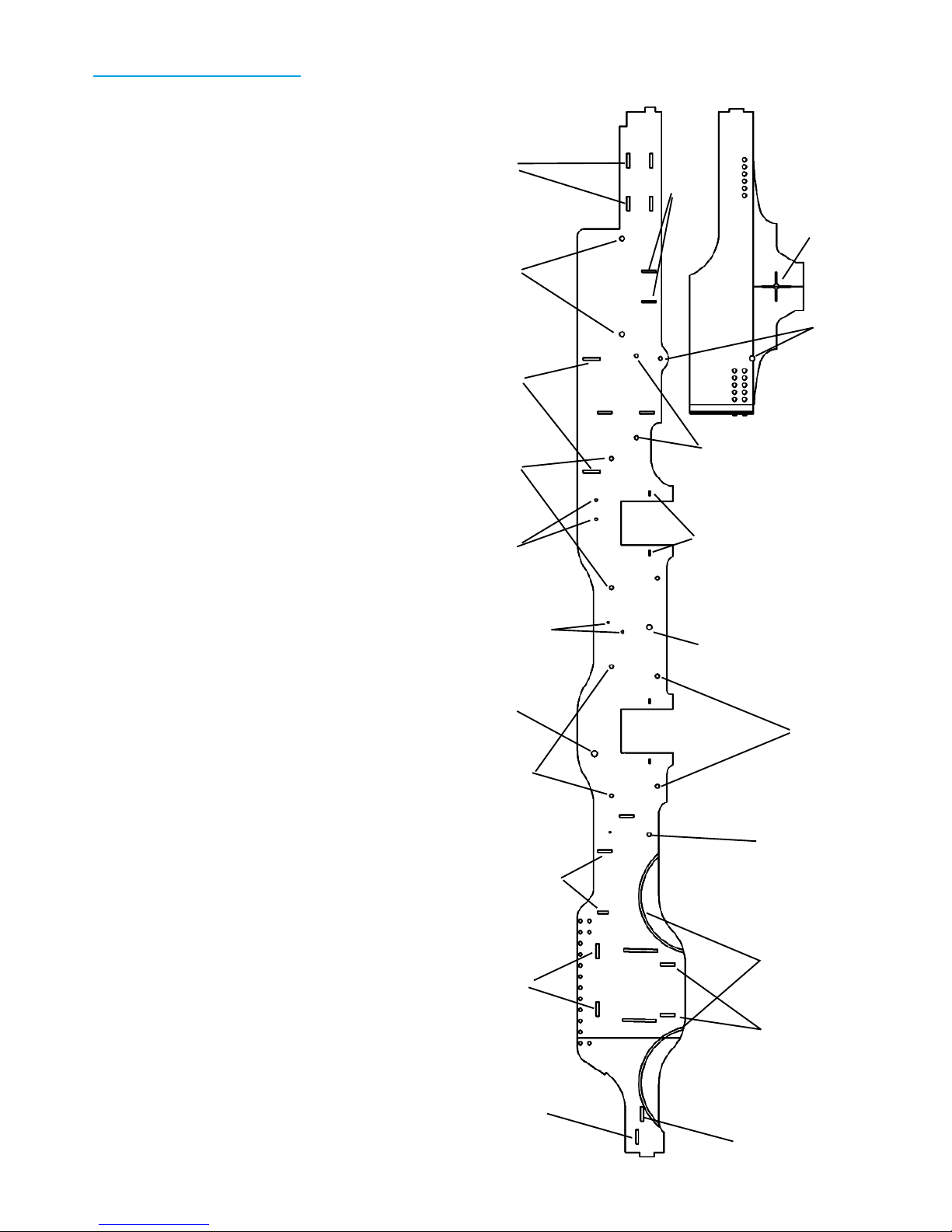
Drill out the frame stiffener locating holes to 0.3 mm in Frame
Left (1) and Frame Right (2) - see picture right.
Measure the short handrail tails which will be used for the
springs (they will be about 0.7 mm diameter) and then drill out
the 6 spring mount positions shown (and marked as 0.65 mm in
the picture on the right) if you require active springing. Push the
handrails supplied into place on the inside of the frames, using a
length of 0.3 mm steel wire through the holes to align them and
solder them into place. Carefully file off the protruding tails on
the outside of the frames.
Drill out the holes for the cosmetic, removable springs, 6 each
side, which are located either side of the horn block spacing for
the front and rear axles only, to 0.80 mm to clear 16 BA c/s bolts
(not supplied) or 1.05 mm to clear 14 BA c/s bolts (supplied).
Carefully countersink the outer face very slightly for the fixing
bolts.
Drill out the brake shaft holes, 3 each side, to 0.7 mm - see
picture right.
Drill out the reversing arm holes to 0.8 mm - see picture right.
1. Frame Layout
9. Cab Base Support
Wheel Height Centres
Spring Mounts
Cosmetic Removable Springs
12,13,14,15. Rear Frame Spacer
16-18. Centre Frame Spacer
Reversing Arm
19-21. Valve Guide
Fire Box
Brake Shaft
Brake Shaft
Spring Mounts
38. Footplate Fixing Bracket
Cut Out Guides for
small radii running
0.33 mm
0.33 mm
0.33 mm
0.7 mm
0.5 mm
0.5 mm
0.5 mm
0.5 mm
0.7 mm
0.65 mm
0.65 mm
0.65 mm
0.65 mm
24,25. Buffer Supports
11. Smoke Box Base
48. Bogie Mount
26,27. Sand Boxes
0.65 mm
0.65 mm
Spring Mounts
10. Fire Box Base
0.8 mm
Rear Wheel Centre
Rear Wheel Brake Shaft
Rear Wheel Spring Mount
Locators (238,239)

Page 14 GCR Class 8B
Page 14 GCR Class 8B
Remove Rear Wheel Spring Mount Locators (238,239) from the
fret, fold with the etch on the outside and locate in place on the
insides of the frames.
Fire Box
Note
The firebox is inset from the sides of the frames as on the
prototype. This is located into the inside of the frame using
locating holes and brass wire.
Locate Fire Box Left (47), Fire Box Right (46) and Fire Box Brace
(42) on the fret, drill the 0.3 mm holes in the fixing tabs, press
out the rivets from the back and then remove from the fret. Bend
to shape and and solder into place inside the main frames using
0.3 mm wire to locate them. Fit Fire Box Brace (44) at the front of
the fire box at the correct angle to match the front slope.
Scale frame cross members
Locate parts Rear Frame Spacer Stiffener Left (14) and Rear
Frame Spacer Stiffener Right (15). Drill out the very small
locating holes to 0.3 mm. Remove these parts from the fret and
with the aid of some 0.3 mm brass wire locate and solder into
place on the inside of both frames.
Locate parts Centre Frame Spacer Stiffener Left (17) and Centre
Frame Spacer Stiffener Right (18). Drill out the very small
locating holes to 0.3 mm. Remove these parts from the fret and
with the aid of some 0.3 mm brass wire locate and solder into
place on the inside of both frames.
Locate parts Valve Guide Support Spacer Stiffener Left (20) and
Valve Guide Support Spacer Stiffener Right (21). Drill out the
very small locating holes to 0.3 mm and the larger holes to 0.7
mm. Remove these parts from the fret and with the aid of some
0.3 mm brass wire and some 0.7 mm brass wire for the larger,
lower holes locate and solder into place on the inside of both
frames.
Generic frame cross members
On Sheet 3 there are 2 generic cross members for either P4 or
EM. You may wish to use these in place of the scale cross
members. They are labelled as P4 or EM. Choose the locations
you prefer to use bearing in mind possible locations for pickup
wiring and make a light pencil mark. Note that you will probably
not need more than one of these and that it must not interfere
with the action of the Stephenson’s Valve Gear if that is fitted.
2.Fire Box
Left side shown with front
of chassis on the left of
picture
3. Main Frame Spacers
Half view - left side only shown
16-18. Centre Frame Spacer
12-15. Rear Frame Spacer
10. Fire Box Support
9. Cab Base Support
Half view - left side only shown
19-21. Valve Guide Spacer
11. Smoke Box Base
38. Footplate Fixing Bracket
48. Bogie Mount
Optional
Optional
Remove for EM and ‘00’

Page 15 GCR Class 8B
Page 15 GCR Class 8B
Connecting the frames together
Note P4 Only
The frames have a half etch bend close to the front. Now is the time to very carefully bend this inwards (it is only 2 degrees), Use
a pair of flat nosed pliers to hold the frames so that the elongated hole for the cylinder spacers is covered and will be held flat.
The smoke box base is etched to allow for this bend.
Note
The etching process is not always accurate so it may be wise to lightly file the cusp from the spacers where they meet the frames
before fitting, it is usually the tiniest bit that is needed. In an ideal world the width over the frames should be 16.10 mm for P4
and 14.70 for EM. Use +/- 0.1 mm as a general guide although it won’t hurt too much if a little more under sized.
Use the P4 Width Templates (231-235) to check if you do not have a micrometer.
Only solder the next parts solidly into place after they have all been fitted and checked. Even with very light tacking the frames
will be solid enough work on.
Remove parts Cab Base Support (9 or 9EM), Fire Box Base (10 or 10EM), Smoke Box Base (11 or 11EM) and Bogie Mount (48
or 48EM) from the fret, check the tabs are clean, bend to shape and one by one do a test fit into between the two frames.
Solder each of these parts into place very lightly starting with Cab Base Support (9 or 9EM). Ensure it is fitted the correct way,
the larger holes are on the underneath and are there to fit the cab and upper body to the chassis.
Fire Box Base (10 or 10EM) should be fitted in place and initially soldered on one side only.
Remove parts Valve Guide Support Spacer (19 or 19EM), Centre Frame Spacer (16 or 16EM), Rear Frame Spacer (12 or 12EM)
and Rear Frame Spacer Brace (13 or 13EM). Solder these in place checking the width of the frames carefully after each one
(16.20 mm for P4 and 14.80 for EM).
Once these are fitted and you are certain the frame is within the specified width then the Firebox Base (10 or 10EM) can be
soldered up on both sides.
Ensure that the large holes in Valve Guide Support Spacer (19 or 19EM) are clear so that the 2.4 mm tubing can fit in them. The
Smoke Box Base (11 or 11EM), Valve Guide Support Spacer (19 or 19EM) and Bogie Mount (51 or 51EM) can now be added to
the frames.
Check the chassis is still square after soldering each part lightly into place.
Slide Bar Stiffeners
Locate parts Slide Bar Support Left (22), Slide Bar Support Right (23). Drill out the very small locating holes to 0.3 mm and the
larger holes to 0.7 mm - the larger hole is also the brake pivot axle. Remove these parts from the fret and with the aid of the
locating wires solder to the outside of both frames noting that the stiffener part is to the rear of the frames.
Brake Frame Mounts
Remove parts Brake Frame Mounts (69-74) from the fret and
solder to the inside of the frames using 0.7 mm brass wire to
locate. When trimming this 0.7 mm wire do not use a pair of
cutters between the frames since this will seriously distort
them. Use a disc cutter or a triangular file to grind away a cut
in the centre.
Now add the brake spacers - these are used to ensure the
brake shoes are at the correct distance from the frames. They
are made from brass tubing which is 1/16” x 1/32” (1.6 mm x
0.8 mm ) and are 1 mm in length. Solder into place. Later, the
brake shoe assembly will simply clip over this.
Sand Boxes
Remove parts Sandbox Left (26) and Sandbox Right (27) from
the fret and fold to shape - locate the tabs just to the rear of
the smoke box and solder lightly to the main frames.
4. Slide Bar Supports and Sand Box
Slide Bar Support Left (22)
Sandbox Left (26)

Page 16 GCR Class 8B
Page 16 GCR Class 8B
Caveat
It will look nice if you fit the buffers next but it will be wrong
because it may inhibit the ease with which the parts of the
cylinders can be fitted such as when holes need to be reamed
out slightly etc
Cylinders
Note
The Cylinder Spacers (7,8) have a number of guide holes in
them. The inner pair are for the valve guide rod tubing. Just
outside of these are two 0.3 mm holes which can be used as
guides for locating the spacers accurately across the frames
(use the inner pair of these for EM and the outer for P4). There
are also two 0.45 mm holes each end which are used to locate
the Cylinder Heads (52-55). The two rectangular holes locate
the slide bars.
You may wish to consider using the Markits Double Slide bar
and Crosshead (M4CRHDSns) instead of the supplied cross head.
Drill out the 0.3 mm and 0.45 mm holes. Drill the larger, central, holes for the valve rod to 1.6 mm minimum, for an easier fit of
the working valve gear this should be 1.8 mm. Drill or ream the large outer holes to 2.4 mm if you intend to use a tube down the
centre of the cylinders or 2.1 mm for the Markits crosshead. You may choose to drill out the valve rod holes to 2.4 mm as well
and fit 2.4 mm tubing.
Remove Cylinder Spacers (7,8) from the fret and fix into the correct position using 0.3 mm brass wire as a guide, the outer holes
are for P4 and the inner holes are for EM. The cylinder tubes fit in the central end holes with the two rectangular holes used to
locate the slide bars.
Drilling Note
When drilling out the cylinder heads it may help to stabilise them if you solder temporarily a length of 0.9 mm brass wire across
one side since drilling them to 2.4 mm will put quite a strain on the tag holding them into the etch. An easier way to drill out
these 2.4 mm holes may be to temporarily solder the part to a bit of scrap and then drill, then un-soldering and fitting as normal.
Drill the two small holes in Cylinder Heads (49-52) to 0.45 mm. Drill the large centre hole to 2.4 mm or for the Markits crosshead
2.1 mm. Remove Cylinder Heads (49-52) from the fret and solder securely in place on the front of the front cylinder support
and the rear of the rear cylinder support using 0.45 mm brass wire to align them.
For the supplied crossheads, fit a length of 3/32” x 1/16” brass tube (2.4 mm x 1.6 mm) so that it is just proud at the front and is
2 mm proud at the rear, 14 mm in total. At the front this fits into the Drwg. 212 Cylinder Front. The front cylinder cover will have
a 1.6 mm tail rod (or the cut down version later) which will help to locate it into the cylinder block.
Slot short lengths of 1.6 mm rod through the inside holes of the Cylinder Spacers (7,8) so that it also runs through the Valve
Guide Spacer (19). Then slot a short length of 2.4 mm tube into the Valve Guide Spacer (19) so that at the rear there is 2 mm
showing and about 4 mm at the front. This will align the rods to the valve chest if fitted along with the Stephenson’s Valve Gear
and simulates the bearing and oiler on the full size locomotive. Solder this in place and remove the 1.6 mm rod.
Slide Bars
Note
Alternatively, the slide bars may be made up from 1 mm x 1 mm nickel silver bar, soldering one part on the top of the other and
filing to shape or using 2 mm x 1 mm bar and again filing to shape.
Parts 125-140 form Qty 4 identical slide bars. These are built up in four layers and soldered together with the aid of 0.3 mm brass
wires to locate and secure the individual layers. These are then filed to the correct shape.
Note that the short layer at the top is positioned the correct way around!
Remove Slide Bar Left Upper Main (125) (long), Slide Bar Overlay (127) (long with half etch section), Slide Bar Overlay (128)
(medium) and Slide Bar Overlay (129) (short) from the etch. Locate using 0.3 mm brass rod and solder up well using high
melting point solder with Nealetin as the flux - or similar.
5.Cylinders and Slide Bars
Cylinder Spacers (7,8)
Cylinder Heads (49-52)
Slide Bar Assembly

Page 17 GCR Class 8B
Page 17 GCR Class 8B
Complete the other slide bar parts as above and file to correct profile. They should be 1 mm wide and at the deepest point 1.2
mm.
Insert a pair of slide bars into each side of the frames and check they locate correctly and not too tightly into the cylinder head
rectangular slots with a small protrusion at the front. Ensure that they fit between the Slide Bar Supports (22,23).
Do not solder up at this stage, first the crossheads must be assembled and then tested for a smooth sliding fit! It is likely that a
small adjustment with a file will be needed to the slide bar supports to achieve the desired 4.66 mm spacing all along the slide
bars.
Crossheads
Note
An alternative to the crosshead assembly provided is the Markits Double Slide bar and Crosshead (M4CRHDSns). However, while
this looks very nice it is not deep enough between the slide bars, which means that the locating holes in the cylinder heads must
be adjusted very slightly inwards. The upper and lower slots of the cross heads must be slightly widened to suit the slide bars.
The Crossheads provided are built up in layers. There are two outer layers (one of them partly half etched to show the profile),
two inner layers one of which is half etched and two inside layers which are shaped to allow the Connecting Rods to partially
rotate. All of these should be used unless you are confident of great accuracy in which case the half etch layer may be left out.
Remove the two sets of Cross Head parts (171-184) from the fret and align each set locating them in place with a steel pin or
something else suitable through the centre into several layers of balsa or other hardwood. If using hardwood such as Ramin
then drill a hole as deep as possible to suit the steel pin. In preference use a higher melting point solder than normal and use
lots of heat. This will allow the parts to be re-aligned should they
move.
Solder these layers together. Do not pick this up too soon, it will
have got very hot!
Trim and file to finish, the top and bottom edges should be filed
down to less than the depth of the slide bars. Do a test fit to
make sure these slide easily.
In the end of the cross heads drill a small hole 1.6 mm to accept
the cross head rod which is 1/16” brass rod of length 25 mm.
Solder this in place ensuring that the cross head is securely
clamped. Do a test fit to ensure it slides easily into the cylinder
tubing.
Check the measurements for the sliding faces on the crossheads
- this should be 4.67 mm for the supplied version (equivalent to
1’ 2”). For the corresponding slide bars the distance between
them is 4.8 mm. Ensure this is the case, filing and trimming as
needed. This will make a nice close fit without being too tight - a
little oil helps here.
7. Cross Heads
Cross Head Rear (171)
Cross Head Overlay (173
Cross Head Top Overlay (183)
Cross Head Inner Layers A
Cross Head Inner Layers B
6. Slide Bar Measurements

Page 18 GCR Class 8B
Page 18 GCR Class 8B
File down the top and bottom carefully so that they do not hit
the Slide Bar Supports (22,23) and can move freely along the
length of the slide bars.
Coupling Rods
Note
The coupling rods are a mirror pair - so take care that all the oil
boxes end up at the top!
A range of extra parts are provided either full depth or half
etched to be attached to the bosses on the coupling rods either to
the front or the rear. These will allow you to choose how far to
off-set the wheels from the coupling rods. The boss at the rear of
the coupling rods is optional.
There is very little space behind the connecting rod in P4 so if
using the Alan Gibson crank pins and locknuts then the leading
hole in the Coupling Rods Left and Right Front (105,111) should
be opened up to 1.8 mm so that the locknut can fit into into it in
reverse. In Extremis is it just possible to open out the hole in
either top boss or the overlay to 2.5 mm so that the whole nut is
countersunk.
A better solution may be to use the crank pins designed by Tim
Venton (see Scalefour Society Forum). These are threaded and
the front one is countersunk into the coupling rods hole.
Drill 1.5 mm to 1.6 mm through all the other crank pin holes to
suit your crank pin bearings. The front crank pin is rather shorter
than on the other axles if the crank pin nut is reversed.
Drill out the coupling rods to suit your choice of crank pins.
Remove Coupling Rod Left (105), Coupling Rod Left Overlay
(106) from the fret.
Remove Coupling Rod Bosses (107-110) from the fret, select and
solder in place to inside and/or outside of main coupling rods.
Repeat for the right side coupling rods using parts (111-116).
Connecting Rods
Note
The Connecting Rods are a mirror pair.
Remove parts Connecting Rod Left (117), Connecting Rod Left
Overlay (118), Connecting Rod End Overlay (121) (square),
Connecting Rod End Overlay (122) (round) from the fret and
solder together.
The hole which fits over the centre axle crank pin should be
opened out to (1.5 mm to 1.6 mm) to suit your crank pin bearing.
The small end of the Connecting Rod should fit inside the
Crosshead Assembly and is secured with a 0.5 mm rivet (lightly
hammer in place or soldered on the rear according to
preference). A short piece of 0.45 mm brass wire will suit as well.
Leave the front slightly proud to represent the fixing bolt.
Repeat for the other connecting rod.
Buffers Beams - rear
Note
9. Connecting Rods
Connecting Rod Left Overlay (118)
Connecting Rod Left (117
Connecting Rod End Overlay (121)
Connecting Rod End
Overlay (122)
8. Coupling Rods
Coupling Rod Left Overlay (106)
Coupling Rod Bosses
Coupling Rod Left (105)

Page 19 GCR Class 8B
Page 19 GCR Class 8B
There is no reason why the buffer layers should not be made part
of the foot plate and soldered to the ends of the footplate using
the rear and front foot plates and the valences as a guide, which
may make fitting body and chassis together a little easier. If this
is done the tabs on the ends of the frames should be carefully
filed flat since they will no longer have a purpose.
The rear buffer has two layers. Drill holes 0.45 mm in Rear Buffer
Beam (5), Rear Buffer Beam Overlay (6) and Rear Buffer Housing
Plates (38,39). Drill large holes in Rear Buffer Beam Overlay (6)
and Rear Buffer Housing Plates (38,39) to 2.0 mm which will
locate the un-sprung rear buffers.
The Rear Buffer Beam (5) has four slots for the frames, the outer
pair of each pair is for P4 and the inner pair is for EM. The outer
pairs are for the secondary (external) frame.
Remove Rear Buffer Beam (5) from the fret and solder over the
end of the frames ensuring it is the right way up, the two slots
are nearer the bottom.
Remove Rear Buffer Beam Overlay (4) from the fret and solder
half etched Rear Buffer Beam Overlay (6) in place again ensuring
it is the right way up. The holes and slot are nearer the top.
Remove Rear Buffer Housing Plates (36,37) from the fret and
solder into place. Ream out the central holes and fit the Cast or
turned Rear Buffers.
Remove Rear Buffer Beam Draw Bar Plate (41) from the fret and
solder it in place to match the draw plate slot.
Fit Drwg. 216 Rear Buffers in place and solder.
Secondary Frame
Push out the rivets if required in Rear Frames (236,237) and
remove them from the fret.
Bend so that the half etch is on the inside and insert into the
sides of the frame and one of the outer pair of slots in the rear
buffer depending on whether you are modelling in P4 (outer) or
EM (inner).
Buffers Beams - front
Note
The Buffer Mounts (32,33) are optional. When first built they
were not fitted but were added later. The rear part of the Gibson
buffers (small circle with a hole in the centre) may be mounted
behind the buffer beam, in which case a small notch needs to be
filed to accommodate it. The four small holes in the corner may
be used to locate the buffer mounts and again optionally, the
Gibson buffers may be drilled out in each corner to 0.45 mm so
that the fixing bolts may be simulated.
The front buffer has two layers. To simulate the bolts that hold
the buffers to the buffer beam drill the locating holes in Front
Buffer Beam (3), Front Buffer Beam Overlay (4) and Buffer
Mounts (34,35) to 0.45 mm.
Remove Front Buffer Beam (3), Front Buffer Beam Overlay (4),
Buffer Support Left (24), Buffer Support Right (25) and Buffer
Mounts (32,33) from the etch.
11. Rear Buffer B (from front)
Slots for frame tabs (P4 outer)
Slots for frame tabs (EM inner)
Front Buffer Beam (3)
Front Buffer Beam Overlay (4)
Frames - shown in
P4 mode - curved
inwards
12. Front Buffer A
Front Buffer Beam
Draw Bar Plates
(39,40)
Buffer Mounts (32,33)
10. Rear Buffer A (from rear)
Rear Buffer Beam (5)
Rear Buffer Beam
Overlay (4)
Rear Buffer Housing Plates (36,37)
Rear Buffer Beam Draw Bar Plate (41)
Drwg. 216 Rear Buffers

Page 20 GCR Class 8B
Page 20 GCR Class 8B
Solder the buffers to Buffer Mounts (32,33) then drill through
0.45 mm from the rear for the corner fixing bolts.
Remove Foot Plate Fixing Bracket (38) from the fret and fit
between the frames. This part should have the TABS removed
and then it can sit either above or below the TABS from the
Buffer Supports (24,25). Fitting it below will allow a deeper 10 BA
fitting to be used under the footplate.
Note
Before fitting the buffer beams permanently it is worth checking
that the valve rod guides and cylinder guides are clear and
accurately set. It is difficult to check these with the buffer beams
in place.
Fix the Front Buffer Beam in place to the frames at the same
time as the Buffer Supports noting that the buffer beam slot is
closer to the top. Check the front buffer beam is square since for
P4 the frames have a distinct bend at 4’ from the front buffer
and if the bend if different at each side the buffer will not be
central. P4 and EM modellers use the same front slot for the
frames.
Ensure the Front Buffer Beam (3) is flat and then using 0.3 mm
brass wire and a couple of clamps locate the buffers, Front Buffer
Beam Overlay (4) and Buffer Mounts (34,35) and solder carefully
into place. Trim off the 0.3 mm wire to represent the bolt heads
on the buffers.
Remove Front Buffer Beam Draw Bar Plates (39,40) from the
fret, clean up where needed and solder into place.
Remove Couplers (34,35) from the fret and solder into the front
buffer beam.
Brake Cylinder Support
Remove parts Brake Cylinder Supports (28,29) from the fret, drill
the smaller hole to 0.45 mm (this takes the safety chain link to
the tender) and drill the larger hole to 1.0 mm for the actuating
axle for the brakes.
Solder into place under Cab Base Support (3) and check they are
square to this base.
Fit the cast/turned/printed Drwg. 218 Vacuum Cylinder after all
soldering is completed.
Stephenson’s Valve Gear
Note
The Stephenson’s Valve gear consists of mirror images of parts on
the centre axle. They can be configured to work by locking them
to the centre axle or may be left to rotate freely.
Make sure that the correct parts are on the outside or the
eccentrics may become twisted. Also note that parts for the
eccentric have a ‘tab’ on them and additional fixing holes to help
in getting them soldered up. After soldering these and before
fitting into the main motion these tabs are filed to the correct
shape. High melting point solder is recommended. Brass wire 0.3
mm is used to locate the parts accurately.
For parts 185-200 drill out all the locating holes to 0.3 mm.
14. Brake Cylinder Supports
Brake Cylinder Supports (28,29)
Left frame only shown, Cab
Base and Rear Buffer
15. Valve Gear Outer Rod
Valve Rod Right Outer (187)
Outer Rod End Strips (189,190)
Outer Rod Spacer (193)
16. Valve Gear Inner Rod
Valve Rod Right Inner (188)
Inner Rod Spacer (199)
Inner Rod End Strips (195,196)
Buffer Supports (24,25)
Foot Plate Fixing
Bracket (38)
13. Front Buffer B

Page 21 GCR Class 8B
Page 21 GCR Class 8B
Valve Rods
Start with the valve gear for the right hand side.
Remove Valve Rod Right Outer (187) and Valve Rod Right Inner
(188) from the fret. With a small piece of wet and dry paper ease
out the large holes to 5.7 mm so that they revolve easily round
the brass eccentric plates (Drwg. 215).
Remove Outer Rod End Strips (189,190) and Outer Rod Spacer
(193) from the fret and using a 0.3 mm piece of brass wire locate
these parts as shown and solder up.
Remove Inner Rod End Strips (195,196) and Inner Rod Spacer
(199) from the fret and using a 0.3 mm piece of brass wire locate
these parts as shown and solder up.
Eccentric
Note
Since these parts are the ones that tend to get either lost in the
carpet or are difficult to solder together a rear tag with an extra
locating hole is provided for them.
For the eccentric itself (201,204) drill out the holes at each end to
0.6 mm. These will fit on to the Lifting Arms.
Remove the eccentric parts 201-212 from the fret, complete with
their extensions and use 0.3 mm wire to locate them and solder
together as shown in the diagram.
Clean up as much as possible and cut and file the rear of the
eccentric assembly to shape.
Lifting Arms
For Lifting Arms (213-216), Rotation Arms (217-220), Rotation
Arm End Spacers (221,224) drill out the smaller holes to 0.5 mm
and the larger holes in the bottom end of Lifting Arms (213-216)
to 0.7 mm. This is the end that is locked through the centre of
the eccentric.
Steam Chest Rods
Remove Valve Rod Ends (226,227) from the fret and roll round a
piece of 1.6 mm brass rod on which the ends have been filed flat
over a length of 2 mm, drill through the locating holes and fix in
place by soldering. The flat should be such that the width of the
finished sub-assembly is no greater than 1.6 mm.
At this stage with a little judicious fettling it should be possible
(but only just) to slide this up and down the eccentric. It may be
easier to leave this in the fully up or fully down position since
they may never move when the engine is running.
Fit short lengths of 2.4 mm brass tubing (ideally this should be 4
mm long) into Valve Guide Support Spacer (19 or 19EM) and
using some 1.6 mm brass rod, align it through the Cylinder
Spacers (7,8) ensuring that the rod slides very easily.
Brass Plates
In Drwg. 215 Eccentric there are four plates which fit either side
of Valve Rod Outers (185,187) and Valve Rod Inners (186,188).
There is Eccentric Template (230) on the fret which can be used
17.Valve Gear Eccentric
18. Final Eccentric Shape
19. Lifting Gear
Main Eccentric (203,204)
Eccentric Bracket 205,206)
Eccentric Short Brackets (209,210)
Lifting Arms (213-214)
Rotation Arms (217-218)
Rotation Arm End Spacers (221,222)
20. Valve Rod
Valve Rod End
(226)
1.6 mm Brass Rod
21. Overview of eccentric and lifting gear

Page 22 GCR Class 8B
Page 22 GCR Class 8B
to mark the holes to be drilled. Check that the brass plates will sit
in the hole in the template, using a bit of wet & dry to ease as
needed. Remove this from the fret and fold over with the half
etch on the outside and solder up.
Lay the brass plates in the template ensuring the centre mark is
absolutely central and lightly mark the small holes by drilling with
a 0.45 mm drill.
At this stage it should be possible to do a trial fit with a 3 mm
drill, using a couple of lengths of 0.45 mm wire to fix in place.
Check the plates can rotate within Valve Rod Outers and Valve
Rod Inners without any friction.
There are two ways to fix these permanently, both of which have
proved satisfactory under test. Short lengths of 0.45 mm wire can
be soldered either side of the plates or the second plate can be
drilled out to 0.8 mm and the front counter sunk for a 16 BA bolt.
The first plate is then drilled to 0.6 mm and tapped to 16 BA and
a couple of 16 BA counter sunk screws fitted and trimmed off.
Once fixed and solid the centre hole should be carefully reamed
out to 1/8” to make an interference fit over the axle.
The connectors at the eccentric end of the rod may be trimmed
down to represent a curved connection.
Now do it all again for the left side mechanism.
Reversing Axle and Balance Weight
The Counterweight Weight Drwg. 211 will need a 1.2 mm hole
drilled in the side halfway along into which can be soldered
Balance Arm (225).
Note
For completeness of the reversing axle description the Reversing
Arm Chassis End (70), Reversing Arm Front Actuator (73) and
Reversing Arm Rear Actuators (72,73) are mentioned here. These
are in Brass and are on Sheet 4. Reversing Arm Front Actuator
(73) should be fitted just inside the right frame over the 0.8 mm
axle.
Fold Reversing Arm Front Actuator (72) to create a bend while
leaving Reversing Arm Front Actuator (73) is flat. The Reversing
Arm Chassis End (70) fits inside the open end.
The measurements shown in the diagram of the axle are exact for
P4 although it may be necessary to slightly undercut the spacers
in order to fit the eccentric lifting assemblies and the Balance
Arm (274).
Brakes
Note
All the holes in the brake parts 55-97 are 0.45 mm - make sure
these are clear. A couple of pieces of balsa wood will aid assembly
by forcing brass locating wires through the parts and into the
balsa. 3D printed parts may be considered, glued to the etched
base and will help to obviate shorts.
22. Assembly of brass plates
Right Inner
Right Outer
Eccentric
Brass Eccentric Plates
Drwg. 216
23. Reversing Axle A
Rotation Arms (217-220)
Balance Arm (225)
Reversing Arm
Actuators - see
brass etches
Counterweight
Weight Drwg.
211
Lifting Arms (213,214)
1.6mm tube cut
as spacers on
8mm rod
24. Reversing Axle B
Brake Shoe Top
Layer (87)

Page 23 GCR Class 8B
Page 23 GCR Class 8B
Brake Shoes
Solder Brake Shoe Bases (81-86) to Brake Shoe Top Layer (87-
92) using 0.45 mm brass wire to locate them with respect to
each other.
Make up the brake shoes from Brake Mounts (69-74) and Brake
Mounts Top Layer (75-80) sitting these over the Brake Shoe
Bases and Brake Shoe Top Layers using the 0.45 mm brass wire
to help locate them. These are layered as shown in the
diagram.
Trim the 0.45 mm wire to represent the fixing bolts.
Main Brake Assembly
Remove Brake Pull (61) and the supporting brackets (62-67)
from the fret. Assemble as shown using 0.45 mm brass wire to
locate the parts making sure the right bits point to the front.
Trim the locating wires to represent the fixing bolts.
The rear split hinge is simply a piece of 1.6 mm brass tube
soldered to the rear of the Brake Pull (61) and its Brake Pull
Rear Brackets (62,63). Once fitted this can be cut centrally to
allow Rear Brake Pulls (95, 96) to be fitted.
Ensure the brake shoe assemblies will fit over the ends of the
Brake Pull (61) - gently filing the rectangular ends as needed.
Note that the set next to the Valve Guide Spacer may need
trimming with a file so that it lies tight against the Slide Rail
Spacer at the correct angle.
Rear Brake Assembly
Remove Brake Cylinder Links (93, 94) from the fret, bend to
shape so that Rear Brake Pulls (95, 96) will fit between them.
Remove Rear Brake Pulls (95, 96) from the fret and solder
together. Pin to Brake Cylinder Links (93, 94) using a short piece
of 0.45 mm brass wire. Connect Vacuum Cylinder Link (68) to fit
between the two upper arms.
Test Fitting
Using a short piece of 1.0 mm brass wire locate the rear brake
assembly between the Brake Cylinder Supports (28,29) under
the frames so that the Vacuum Cylinder Link (68) fits into the
Vacuum Cylinder.
Clip the main brake assembly into place, pushing the bottom of
the front brakes right up against the Valve Guide Support
Spacer (20). Solder the brake shoes to Brake Pull (61).
It should now be possible to connect the front and rear brake
assemblies through the split hinge on the rear of the main
brake assembly using a piece of 0.8 mm brass wire.
By removing this piece of wire and unclipping the main brake
assembly it should be a simple matter to drop out the wheels
when needed.
Put all these to one side until final assembly and painting.
These parts are easily damaged.
26. Brake Assembly Pull Rod
Brake Pull (61)
Brake Pull Rear
Brackets (62,63)
Brake Pull Front Bracket
(66,67)
27. Vacuum Cylinder Connection
Vacuum Cylinder Link (68)
Brake Cylinder Link (93,94)
Rear Brake Pull (95)
Rear Brake Pull Tags (97,98)
Small Brake Pull (99,100)
Brake Levers (103,104)
Actuator to Brake
Levers (101,102)
28. Brake Assembly Overview
25. Brake Shoe Assembly
Brake Mount (55)
Brake Mount
Top Layer (75)
Brake Shoe Base (81)

Page 24 GCR Class 8B
Page 24 GCR Class 8B
Drag Link
Note
The drag link is optional, this is just how it is done on the
prototype. The chequered plate between the tender and
locomotive may be simply hooked on the front of the tender using
a couple of pieces of wire.
Optionally the drag link may be made from 1.6 mm NiSi and a
thread, 10 mm long, cut at one end for a spring as in the
prototype, which fits in the space behind the tender front buffer
beam. At the front end, simply hit a 3 mm section with a hammer
from both sides to flatten it and use a pin to fix in place.
Remove Drag Links (43-45) from the fret and solder together. A 5
mm pin through the Cab Base Support (9) front hole will hold it in
place. This should be made removable, there is room under the
cab floor.
The tender end of the drag links should be rounded off, trimmed
to a suitable length and a thread cut over the last 10 mm to
match the fixing position in the tender. With a weak spring fitted
this will give a convincing movement when the locomotive starts
with a heavy load.
Guard Irons
Remove Guard Iron Left (30) and Guard Iron Right (31) from the
fret, bend to shape and solder in place on the insides of the
frames ensuring the front face is vertical and the inset on the
front edge fits just under the bottom of the front buffer beam.
Front Bogie
Note
The Adams Bogie rotates around a central pin and can move side
to side under spring control. This is combined with the
compensating beams fitted on either side of the frame on top of
the axle boxes.
The Adams Bogie was used in many locomotive classes including
the LNER G5 of which a new one is being built. See picture. While
this is not identical to the one in the kit there are many
similarities.
Bogie Frame
Push through the rivets on the reverse of the Bogie Frame (141)
and drill out the four end holes to 0.9 mm.
Solder the Bogie Side Overlays (142,143) in place using a piece of
0.7 mm brass wire to locate them accurately.
Remove Bogie Frame (141) and Bogie Side Overlays (142,143)
from the fret and fold as shown. Note that the outer bends are
folded back with the half etch on the outside since the fold is a
full 180 degrees. Ensure this is square before soldering.
Use a piece of 0.9 mm wire to act as a fixing strap across the
front and rear of the bogie. Leave about 1 mm proud to
represent the end nuts.
29. Bogie Main Frame
Bogie Frame (141)
Bogie Side Overlays (142,143)
30. Bogie Stretcher
Bogie stretcher (148)
31. Bogie Equaliser Bars
Equalising Bars (144-147)
Bogie Spring Hangers (167-170)

Page 25 GCR Class 8B
Page 25 GCR Class 8B
Drill out the 12 holes in Bogie Stretcher (148) to 0.3 mm. These
are a set of alternative fittings for the wire that will spring the
wheels.
Remove Bogie stretcher (148) from the fret, bend to shape and
solder in place underneath Bogie Frame (141) so that the
elongated hole is properly aligned, trying not to block the spring
holes with solder.
Equalising Bars
Note
The pairs of equalising bars fit outside the springs to give an
impression of real depth although for EM modellers it is better to
make these much thinner and only use one spring layer.
The Equalising Bars (144-147), Spring Face Plate (149,150) and
Spring Backing Plates (151-156) have locating holes to help
assemble them. Drill these out to 0.3 mm.
Remove Equalising Bars (144-147), Spring Face Plate (149,150)
and Spring Backing Plates (151-156) from the fret, fold the
Equalising Bars as shown and solder the tips, which sit on top of
the axle boxes, together.
Solder Spring Face Plate (149) and Spring Backing Plates (1151-
154) together for one side and then repeat for the other side.
Solder the equalising bars and springs to the side/top of the main
bogie with the springs between the pairs of equalising bars and
the half etched leaf spring showing. Remove Bogie Spring
Hangers (167-170) from the fret if required and use a piece of
0.45 mm wire to locate.
Drill out the bottom holes in Bogie Frame (141), the holes in
Bogie Side Overlays (142,,143) and the holes in the Bogie Pivots
(157-164) to 0.7 mm.
Remove Bogie Pivots (157-164) from the fret and solder up the
in two sets, making sure the central hole is cleared to 0.7 mm,
file them square and then solder in place over the Bogie Side
Overlays (142,143). Trim and file the 0.7 mm brass wire proud of
the surface then remove the Hex Bolt Heads (165,166) from the
fret and solder these in place.
And finally for the Bogie
Add side play steel spring control to front fixing strap so that it
fits around the Drwg. 225 Bogie Pivot which sits in Bogie Mount
(48).
Glue Qty 4 Drwg. 225 Bogie Axle Box in place but check they are
not over the B-B for your gauge, file the front down to suit.
Add wheels and check the B-B. If needed the front of the axle
boxes may be carefully reduced.
Add Ernie Ball Gauge 12 steel wire for wheel springs - these
should fit lightly over the axles and through one of the holes in
Bogie Stretcher (148) depending on the downwards force
required.
32. Bogie Springs And Hangers
Spring Backing Plates (151-156)
Spring Face Plate (149,150)
33. Bogie Completed
34. Bogie Completed Underneath
Axle Box Spring Mount (106-111)
35. Axle Box Frame
File off if needed
Drwg. 226 Markits
Horn Block

Page 26 GCR Class 8B
Page 26 GCR Class 8B
Add the turned Bogie Pivot (Drwg. 219) to the underside of Bogie Mount (48) on the chassis so that the long part will hang
through the bogie when it is fitted. Add thin washers when testing to increase downwards force if needed.
Fitting wheels
Note
This is where a small block of wood will come in handy since soldering the axle boxes and their spring covers on top of it will
cause them to stick slightly to the wood and thus make it easier to add the brass tubing for the spring wire.
Solder brass parts Axle Box Spring Mount (106-111) over Drwg. 226 Horn Blocks. These parts are on Sheet 4. EM Modellers may
use the EM Blanking Plates on Sheet 3 if springing is not needed.
Cut some short lengths of the 0.8 mm x 0.4 mm tube simply by rolling a sharp knife over it, it will cut very easily and solder these
to the tabs - there is a small notch on the tab to indicate the ideal height. Ensure the hole is free by test drilling with a 0.3 mm
drill.
Clean up and ensure that they are a good fit and will slide easily, but not loosely, in the chassis. If you are fitting the internal
valve gear then fitting the first and second wheel assembly to the chassis may/will be fiddly.
The spring wire supplied is 12 gauge steel guitar string from Ernie Ball. This will fit in the handrail knobs on the insides of the
frames.
Add wheel weights, fitting them opposite to the crank pin will usually be correct ( but see photographs for details). The centre
wheel weights are the larger pair. Use Araldite sparingly for best results.
Note that Gibson wheels will need the rear boss filed off carefully so that they fit as close to the frames as in the prototype.
Driving Axles side play
Front wheel - as little as possible since there is only a very small space between the coupling rod and the back of the connecting
rod. Use a full width spacer. For the centre Wheel use half width spacers
Fit crank pins to wheels and fit wheels to axles, quarter until satisfied
Fit coupling rods and check there is no binding, this should be relatively easy for a 4-coupled locomotive. Note the right hand
lead. Try this with a motor fitted.
Add connecting rods, check they are a free fit in the slide bars before fitting to the centre axle.
Fit reversing axle in place with Drwg. 211 Counter Weight.
Valve Gear (if fitted)
Slide the Stephenson’s Valve Gear on to the centre axle and either fix in place with something like ‘Loctite’ or use a brass pin
through the axle and solder the brass plate inners to these. Alternatively allow the valve gear to revolve freely by reaming out
above the 1/8 axle diameter.
The valve gear must be free to rotate without any binding before any attempt at a final fitting of the coupling rods is made. If
there is a point where binding is felt, it is usually at the eccentric.
Fit the eccentric and valve rods (if you are going to use them) and then fit the gear box over the rear axle.
Slide the axle boxes into position one by one and check there is a good sliding fit. Now test that a spring will fit across the top of
the axle boxes.
Plan to secure the Stephenson’s valve gear around the front axle but it is better to leave the bottom connection as a removable
one using 16 BA C/H nuts and bolts.
Fitting furniture for the chassis
Fit front buffers and springs.
Add 0.9 mm brass wire as a sanding pipes to both side - front wheel only, the rear wheels on this locomotive are done from the
tender.

Page 27 GCR Class 8B
Page 27 GCR Class 8B
Araldite in place Drwg. 212 Cylinder Front - note that Cylinder Covers (97,98) are supplied with extras and are on the N/S etch
and on the brass etch. The cylinder fronts supplied are nickel silver and for early GC days represent the polished and oiled steel
fronts.
These should be soldered in place at the same time to ensure a good fit. Drwg. 212 Cylinder Fronts are drilled to 1.6 mm, a
short piece of 1.6 mm NiSi rod should be fitted to represent the tail rods (long or short), 8 mm proud for the long versions which
lasted until nearly grouping or 1 mm proud for the later, blanked off, version. Note that this NiSi rod should fit inside the 2.4 mm
tube (if fitted) in the cylinder block.
Centre Axle Spring Drwg. 209 if fitted should be super-glued to the bottom of the centre axle box or the EM Blanking Plate if that
is fitted.
Motor, DCC Chip and pickups
Fit motor and test run the mechanism until satisfied everything runs freely. For modellers of the DCC persuasion there are many
to choose from. You may wish to use one of the additional functions to drive a RED LED in the firebox.
Fit as many pickups as possible and wire up. There is plenty of space under the motor for a small piece of PCB. Alternatively rely
on tender pickups, there is plenty of choice in there.

Page 28 GCR Class 8B
Page 28 GCR Class 8B
Window Overlays (64-67)
Cab Front (63)
Cab Side Left (55)
Edging Strip (61)
Half etch from
inside to centre
the brass number
plate - drill out if
needed
36. Cab Front
Body Work
Notes
Parts are included for P4 and EM for both these variants. Take
care not to get the P4 and EM parts confused.
The metal used is 0.3 mm brass. This is delicate, especially so
with these style of locomotives where the foot plates are quite
narrow. Take care when drilling by using a pin chuck, not a
power drill. A number of parts are best assembled while the
larger part is still attached to the fret.
Cab Fronts
With a very sharp blade and a slicing motion remove the
Window Overlays (64-67) from the fret. There are double the
quantity needed. Clean these up using a very fine file while
holding the very fragile part in a pair of flat nosed pliers.
Apply some solder paste around the insets on Cab Front (63)
and solder them into place.
Remove Cab Front (63) from the fret.
Cab Sides
Note
On the inside of the cab sides there is a half etch mark which is
at the centre of the brass number plate if fitted.
Drill through the half etch number plate mark 0.45 mm on Cab
Sides (55,57) if you intend to fit a pair of the GCR brass
numbers. Drill the cab side rail holes to 0.45 mm, note that the
hand rail was set forwards when side screens were fitted, so
choose the right pair.
Remove Cab Side Overlay (56) and Cab Side Splasher Overlay
(59) from the fret and using solder paste, solder into the half
etched sections of the Cab Side (55). These will represent the
brass beading on the splasher and cab side.
Remove Cab Side Left (55) from the fret and gently file round
the cab opening to remove spurious bits of metal .
Remove Edging Strip (61) from the fret and solder around the
cab opening. Do this a very small part at a time and ensure
that the holes at each end line up vertically for the cab side
hand rail.
Repeat for Cab Side Right (57).
Fit cast number plates if required using the guide hole drilled
earlier.
Footplate
Note
The footplate is very floppy, it may often be worth while
soldering a couple of bars along the tops as a temporary
measure.
Remove Footplate Assembly Aid (136) from the fret, drill out
the holes to 0.45 mm, fold up at a right angle and solder firmly.
This piece is used to separate the foot plates at the correct
0.45 mm for hand rail
0.45 mm choose front
or rear pair,
rear pair for
early days front pair
when sightscreen added
37. Cab Side (Left)
38. Cab Side (Left) Inside View
Cab Side Left (55)

Page 29 GCR Class 8B
Page 29 GCR Class 8B
Balsa Base
Footplate Assembly Aid (136)
Cab Sides (55,57)
Foot plates (9,10)
Cab Assembly Aids (137,138)
distance using locating holes towards the front of the
footplate. On the foot plates these holes later become the
location for oil boxes and sand box fillers. The semi-circular
recess in Footplate Assembly Aid (136) will help locate the
boiler later on and should be towards the rear.
Select the correct foot plate pair, Foot Plate Left (9) and
Footplate Right (10) or if modelling in EM Foot plate Left (9EM)
and Footplate Right (10EM). Drill the holes to match Footplate
Assembly Aid (136) to 0.45 mm and the foot plate grab rail
holes to 0.3 mm. Remove Foot Plate Left (9) and Footplate
Right (10) from the fret.
Using a couple of pieces of balsa as a base lightly solder
Footplate Assembly Aid (136), Foot plate Left (9) and Footplate
Right (10) together. The rear end of the footplate should
overhang the balsa by about 20 mm. It is worth while checking
this assembly is square. The width should be 33.0 mm +0 mm
-0.2 mm. Use brass pins into the balsa to hold this in place.
Subsequent work will lock this in place and the measurement
is just a guide.
Fitting Cab Sides
Remove Cab Assembly Aids (137,138) from the fret, fold at a
right angle and solder up.
Insert Cab Sides Left (55) and Cab Side Right (57) into the
footplate using the front and centre slots only. The rear tab
should overhang the balsa. Use Cab Assembly Aids (137,138)
as shown to assist in getting these vertical.
Firebox
Note
The front of the fire box will need filing to shape, there is a
template supplied but it is simple to do this by eye. There are
two ways to prepare for this - read on.
Either way the fire box front curve is bulked up will cause the
assembly to get rather warm. Use clips to hold the parts firmly
and insulate when holding the parts.
The simple way to prepare the front of the fire box for filing is
to drop some solder in the corners, covering the area with flux
and then slowly add more solder with a very hot iron.
A better way may be to use Fire Box Braces (51-54) to build up
a solid foundation.
Filing this area will allow the correct fire box curve at the front.
Use Belpaire Filing Aid (141) to guide the filing, better to have
too little than too much removed.
Remove Fire Box (44) from the fret and carefully remove all
tags but even more carefully leaving the Tabs that will locate
this into the front of the cab.
Remove Fire Box Support Aids (139,140) from the fret. Drill
out the four holes in each to 0.45 mm and drill out the
corresponding holes in the side parts of the fire box. Roll the
main fire box to shape using a piece of 4 mm rod (or a drill)
with the half etch on the inside and bend the side and top
parts inwards, locate it with the Fire Box Support (139) and
0.3 mm Hand Rail
0.45 mm
Cab Front (63)
40. Footplate and Cab (2)
39. Footplate and Cab
41. Fire Box Bracing
Fire Box Support Aid (139)
Fire Box Braces (51-54)

Page 30 GCR Class 8B
Page 30 GCR Class 8B
lightly solder. This may be removed later once the assembly of
the fire box is finished.
If you wish to bulk up the inside of the fire box then remove
Fire Box Braces (51-54) from the fret and insert into the inside
of the fire box using the same 0.45 mm wires to locate
securely and accurately - then solder up using lots of heat.
Now curve the splasher part of the cab front that fits over the
wheels to shape using the fire box as a guide, it is better that
this is slightly over-curved since it will be easier to solder in
place. Note also that the curve starts just below the
rectangular hole for the reversing lever. The half etch at the
bottom should just fit onto the footplate.
Locate the fire box into the front of the cab using the six slots
provided - take care that the fire box sits flush since it will be
difficult to adjust later.
Repeat this with the part of the fire box that fits inside the cab.
Remove Fire Box Cab (45) and the second Fire Box Support
(Aid 140). There is only one tab which locates centrally at the
top.
Once the fire box is secure and square, solder can be run
round the various joints.
If you want to fit the Inspection Covers (46-50) (not always
fitted - see photographs) to the curved part of the fire box
then remove Inspection Covers (46-50) from the fret, curve to
shape and solder in place. These are fitted along the centre of
the curved part of the boiler and at 3 mm, 13 mm and 23 mm
from the front of the cab on the left and 8 mm and 20 mm
from the front of the cab on the right side. These have a
nominal spacing of 2’ 6”.
Add Washout Plugs (8) to both sides of the fire box.
Fitting Cab Front & Sides
Position the cab front BETWEEN the cab sides. The half etch
end on the end of the splasher will lie flat on the footplate.
Very lightly solder the top corners first to get the position
correct and then slowly complete the soldering around the
curve.
Front and Centre Splashers
Remove Splasher Sides (20-23) from the fret and solder onto
the footplate ensuring that the half etch representing the
brass trim is on the outside.
Remove Splasher Tops (26-29) from the fret, roll to shape so
that the half etch parts are on the inside of the curve, bending
over the half etch ends so they will lie flat on the footplate and
solder into place. Note that the splasher tops fit level with the
top of the Splasher Sides and NOT on top of them!
Note that the rear pair of the splashers should be trimmed so
that they fit between the Splasher Side and the Fire Box side
since they will not fit under the fire box side.
42. Fire Box Arrangement
Fire Box Cab (45)
Fire Box (44)
Inspection
Covers (46-50)
Washout Plugs (8)
Fire Box Support Aid (140)
43. Fire Box Arrangement Inside Cab
44. Splashers
Splasher Sides (20-23)
Splasher Tops (26-29)

Page 31 GCR Class 8B
Page 31 GCR Class 8B
Cab
Cupboard
Locating
Tabs
Frames
Foot Plate Rear (11)
10 BA Nuts on top
46. Rear Footplate and Cab Floor
Hinges (77,78)
Position of Foot
Board Left (81)
Position of Shelf Left (83)
Door Knob 0.3 mm brass
Rear Foot Plate
Remove Footplate Rear (11) from the fret and fold up the
centre section, the tabs of which will act to locate the Cab
Floor (89).
Ease the slot out that will fit over the chassis frames with a
little wet & dry. Footplate Rear (11) can now be slid onto the
chassis over the ends of the frames. Solder a couple of 12 BA
nuts in place on the top so that the chassis and body can be
screwed together later. Check the holes are in line and are
clear.
Roll the half etched section into a curve to form the front end
of the footplate, noting that the half etched parts will be on
the underside, trim very slightly if needed. The end should sit
under the end of the foot plate.
Cab Floor
Remove Cab Floor (89) from the etch and fold up the three
ends so that they will lift the cab floor from the rear footplate.
Bend upwards, by about 45 degrees, the two side pieces, these
will curve so that they become part of the splasher inside the
cab. The slots in these curved parts will locate on the tabs of
the part of the fire box inside the cab.
Cab Cupboards
Solder a couple of Door Hinges (77-80) on each of the Cab
Cupboards (75,76) over the holes and add a 0.3 mm piece of
wire to represent the threaded part of the hinge.
Drill through the door knob holes 0.45 mm. Solder in a short
piece of 0.45 mm brass wire to represent the door knob.
Remove Cab Cupboards (75,76) from the fret and fold to
shape and check that they locate into the slots in Cab Floor
(89). Very lightly solder in position.
Remove Footboards (81,82) and Shelves (83,84) from the fret
and fold with the half etch on the inside (this is to give the
impression of a curved edge to the wooden boards). Solder or
glue in place on the bottom part of the cupboards and the top
part of the cupboards respectively. Ensure there is a small
overlap at the rear. The reversing gear will sit on top of the
right shelf.
Check that the cupboards will lock in place using the two
bottom tabs but don’t solder up yet. The outside of the
cupboards sits against the cab sides, so check the assemblies
fit comfortably. The cupboards should be easily removable for
painting if needed.
Cab Roof
Note
The cab roof has ‘T’ and ‘L’ sections which are from milled
brass. These can be bent carefully to shape but it is easier to
Cupboard Left (75)
45. Rear Footplate
Rear Footplate (11) locating tabs fit here
47. Cupboards

Page 32 GCR Class 8B
Page 32 GCR Class 8B
Roof Blanking Plate (126) - if required
‘T’ Shape Brace
Roof (68)
‘L’ Shape Brace
anneal these first and then bend them. The ones supplied in
2014 are almost correct to size and are 0.8 mm across key
dimensions.
Remove Roof (68) from the fret and curve to shape.
The hole in the roof should be to the front and is for the
whistle. The whistle was later moved to the front of the cab
when the LNER reclassified the locomotives. In this case
remove Roof Blanking Plate (126) from the fret, push out the
rivets and solder on top of the roof.
Anneal the shaped brass ‘L’ and ‘T’ sections using the domestic
gas cooker jets or similar when the management is attending
to other matters.
Curve the ‘L’ shaped brass and solder to the front and rear of
the roof. There is a short piece of ‘L’ that fits between the
front and rear sections.
Curve the ‘T’ shaped brass and solder to the centre of the roof
or centre it at 11.5 mm from the front to be accurate.
Check the roof fitting but do not solder in place until the cab is
fully painted. Use the Cab Assembly Aids (137,138) to assist
alignment.
Footplate Supports
Note
These may be left off, they are tricky to get exactly in place and
are hidden behind the valence for the most part.
Remove Footplate Supports (30-33) and Footplate Supports
Tops (34-37) from the fret. Solder together the pairs. For the
front pair it is useful to file down the outside by 0.3 mm (the
width of the brass sheet) so that the supporting plates for the
centre steps may be fitted between them and the valence.
Solder these under the foot plates to locate centrally on the
two stubs of the foot plate.
Centre Steps
Note
Alternative chequer steps are provided for the centre steps
48. Cab Arrangement 1
49. Cab Arrangement 2
51. Roof
50. Cab Arrangement 3
Foot Plate Support Top (30)
Foot Plate Support Bracket (34)
52. Foot Plate Support

Page 33 GCR Class 8B
Page 33 GCR Class 8B
Centre Plate Left Upper (91)
Centre Plate Left (90)
Centre Plate Lower Left (92)
Rear Step Plate Left (96)
Rear Steps Stabiliser (99)
Rear Step Left Lower (98)
Rear Step Left Upper (97)
Remove Centre Step Plate Left (90), Centre Step Left Upper
(91) and Centre Step Left Lower (92) from the fret. Bend
Centre Step Plate Left to shape as shown, there is a distinct
kink a few inches below the valence to move the steps away
from the loading gauge but in reality the displacement is only
the thickness of 0.6 mm.
Fold Centre Step Left Upper (91) to shape noting the the rear
part that attaches to the main plate folds downwards. Solder
into place.
Fold Centre Step Left Lower (92) into shape and solder into
place.
This will now fit between the foot plate supports and the
valence - but it may be better to do this later.
Repeat for the centre steps on the right side.
These fit behind the valence but final fitting should be done
later since handling errors can easily bend these out of shape.
Rear Steps
Note
Alternative chequer steps are provided for the rear steps
Remove Rear Step Plate Left (96), Rear Step Left Upper (97)
and Rear Step Left Lower (98) from the fret. Bend Rear Step
Plate Left (96) to shape as shown, there is a distinct kink a few
inches below the valence to move the steps away from the
loading gauge, noting the displacement is only 0.6 mm.
Fold Rear Step Left Upper (97) into shape and solder into
place.
Fold Rear Step Left Lower (98) into shape and solder into
place.
Repeat for the rear steps on the right side.
Leave the Rear Steps Stabilisers (99,103) until final fitting of
the steps to the body - just in case!
The steps will later fit behind the valence .
Valences
Note
If you have chosen to fit the buffer assemblies (front and rear)
to the foot plate, now is the time to solder them in place.
It may also seem convenient to line up the valences with the
tabs from the splashers and cab sides, this is discouraged
because the alignment aids will not work.
Tabs from the splashers may interfere with fitting the valences
so ensure they are filed flat against the underside of the foot
plates.
Remove Valences Left & Right (18,19) from the fret and very
carefully file off any remaining tags. There is a reverse curve in
the valence under the place where the foot plate widens so
53. Centre Step
54. Rear Step 1
2 deg. kink
55. Rear Step 2

Page 34 GCR Class 8B
Page 34 GCR Class 8B
curve the valences to suit then solder into place against the foot plate support brackets (34-37) with the steps in position
temporarily).
56. You are here 1
58. You are here 3
57. You are here 2

Page 35 GCR Class 8B
Page 35 GCR Class 8B
Use Valence Spacing Aids (132-135) to get the position as
accurate as possible. Two of these are slightly longer and are
used in front of the valence bend but not before the frame
bend begins - i.e. over the cylinders.
You Are Here
Just as a summary, the picture shows the parts made so far. Its
time to start making this thing look like a steam engine.
The cab base should slide over the end of the chassis frames,
ensuring that ALL of the slot in the cab base is taken up. Place
the cab body and foot plates on top of this so that the rear tab
on the cab sides locates in the cab base as well as the hand
rails, it may be necessary to ease the front of the foot plates
over the rivets in the frame.
When satisfied this is square solder up.
Place the cab cupboards and solder both to the cab floor and
the cab side. Very little solder is needed here, they should be a
snug fit. The foot plate overlaps the rear buffer by about 0.5
mm which is the depth of the rivets!
Boiler
Note
The boiler will slide into the smoke box by about 5 mm. Note
that the half etch marks on the boiler must line up with the
firebox and smoke box.
Do not be tempted to solder the splashers to the boiler too
early. They should be an accurate fit if the footplate is straight.
Remove Boiler (1) from the fret and roll to shape with the
locating marks on the outside. The longitudinal ends should
meet exactly.
Remove Boiler Front (2) and Boiler Rear (3) from the fret and
solder into place. Check these are a good fit inside the boiler.
After removing Fire Box Support Aid (139) from the front of
the fire box check that it is a good fit. Make sure you are
finished with filing the Belpaire curve.
Fit Hand Rail Knobs (Qty 4 2 mm, two each side) once you are
satisfied with the fit. If you do it now you can solder from
inside the boiler and get a better joint.
At the same time fit a 2 mm Hand Rail Knob either side of the
fire box.
Note
For EM and for P4 where there is a lot of side play it will be
necessary to remove part of the boiler by grinding until the
wheel will not short on the boiler. The same ‘L’ section used for
the roof of the cab may also be used (see Part 30 in the chassis
section) between the splasher and the boiler, it was there on
the prototypes.
Smoke Box
Remove Smoke Box frame (4) from the fret and fold to shape.
Remove Smoke Box (5) from the fret and roll to shape
ensuring that it is a tight fit over the end of the boiler.
59. Smoke Box Frame
Smoke Box Frame (4)
Top Hand Rail Knob
Smoke Box (5)
60. Smoke Box
Slots for Footplate Front (12)
61. Smoke Box Wrapper
Smoke Box Wrapper (6)
Align with half etch on
boiler just visible.

Page 36 GCR Class 8B
Page 36 GCR Class 8B
There is a hole (used later for the snifter) on the Boiler (1) and Smoke Box (5) to help get the alignment correct. The main
(visible) boiler should be 60 mm long with about 5 mm inside the smoke box assembly.
The circular part of the Smoke Box Frame sits inside Smoke Box and there are two notches to assist in the location. Before
soldering the Smoke Box (5) to the Smoke Box frame (4), ensure that the two sit parallel. If the boiler and/or the Smoke Box
have not been rolled exactly circular then it may be necessary to file away the rear of the Smoke Box Frame until they do sit
parallel. It is difficult, even with roller bars, to ensure circularity where the boiler and Smoke Box joins are made.
Smoke Box Wrapper
Note
There are two smoke box wrappers provided, the one with rivets is for the superheated
version. Both are marked with ‘front’ and ‘rear’ as an aid to fitting correctly.
Remove Smoke Box Wrapper (6) or Smoke Box Wrapper (7)
from the fret and carefully file off the remains of the tags.
Using the hole for the upper lamp bracket, the hole for the
Hand Rail Knobs and the hole for the chimney locate the
Smoke Box Wrapper around the Smoke Box (5) and, ensuring it
is a tight fit, beginning at the top, solder into place.
File the bottom part of the wrapper flat, this is slightly
overlong by design, this will sit directly on the Smoke Box
Base (11) which is part of the chassis.
File the front of the Smoke Box flat. Fit the Qty 2 1.6 mm Hand
Rail Knobs, on either side of the smoke box.
The ash ejectors were always fitted on the right hand side.
Smoke Box Step
Drill the hole in Smoke Box Step (8) and the hole in the front
of the Smoke Box Frame (4) which is on the lower right side to
0.3 mm. Remove Smoke Box Step (8) from the fret and use a
short length of 0.3 mm brass wire to locate the step in
position. Solder into place and clean up.
Smoke Box Front Hand Rail Knob
Ensure that the hand rail knob will fit into the hole at the top of the smoke box. Do not solder in place yet, it will be impossible
to get a good fit on the hand rail unless this is left right until the end.
Front Foot Plate
In Footplate Front (12), drill three holes to 0.3 mm for the lamp brackets , drill one hole 0.8mm for the vacuum pipe and two to
0.3 mm for the knobs on the curved part next to the smoke box.
Solder a couple of 10 BA nuts to the underside locating over the half etch circles.
Remove Footplate Front (12) from the fret. Bend the Foot Plate Front (12) to the correct curve so that the half etched lines will
be on the under side.
Insert the tabs on Front Foot Plate (12) into the two slots on the front of the smoke box.
Add Footplate Hinges (14,15) at the joint line and add a short piece of 0.3 mm brass wire to represent the hinge.
Insert a couple of short lengths of 0.3 mm wire near the top to represent the knobs used to open the ‘piano’.
Boiler and Smoke Box
Ensure that the rear end of the boiler is a good fit and the front end of the smoke box will sit between the frames.
Solder the boiler rear to the fire box keeping the two location marks aligned exactly. Once satisfied that it is never going to be
moved solder them firmly together from underneath.
Vacuum Pipe Location
Lamp Brackets 16-18)
Foot Plate Front (12 )
Hinges (14,15)
Handles
62. Footplate Front

Page 37 GCR Class 8B
Page 37 GCR Class 8B
Hand Rail
Bend a length of 0.45 mm brass wire to suit the curve at the front of the smoke box, thread on the Hand Rail Knob for the smoke
box and push the two ends through the hand rail knobs on the smoke box and boiler sides and into the holes just under the cab
front windows. Solder into place inside the cab then solder the hand rail on the front of the smoke box into place if needed, use
a dab of glue in preference.
Lamp Brackets
Note
The supplied brackets have an etched bend which is vulnerable to mishandling. An alternative is to use a short length of 1 mm
wide brass and make a sharp fold in it. Staples have been recommended elsewhere as another customer choice.
Drill out the locating holes in Lamp Brackets (15-17). Remove Lamp Brackets (15-17) from the fret, bend to shape and fit to foot
plate using 0.33 mm brass wire to locate them.
Trim any excess wire and file down.
Vacuum Pipe
Locate the Markits Vacuum Pipe. Drill out the corresponding hole in the front foot plate and solder into place. Ensure it is
vertical.
Hand Rails (Cab Side)
Fit a short length of 0.45 mm brass wire into the two holes on the cab sides. This should be about 0.9 mm from the cab side.
Foot Plate Grab Handles
If the centre steps are fitted then there should be a grab handle on the footplate. Clear the holes in the foot plates between the
leading and centre splashers to 0.45 mm and fit a short length of 0.45 mm brass wire setting it to 0.9 mm above the foot plate.
63. Reversing Arm Assembly
Reversing Arm Front Actuator (74)
Reversing Arm Cab Arm (71)
Reversing Arm Chassis End (70)
Reversing Arm
Rear Actuator
(72,73)
Reversing Arm Cab End (69)
Scrap 2 mm x 2 mm x 2 mm drill 0.45 mm
Fit to reversing axle

Page 38 GCR Class 8B
Page 38 GCR Class 8B
Foot Plate Grab Handles
If the centre steps are fitted then there should be a grab handle on the footplate. Clear the holes in the foot plates between the
leading and centre splashers to 0.45 mm and fit a short length of 0.45 mm brass wire setting it to 0.9 mm above the foot plate.
Reversing Arm
Note
The reversing arm consists of several very fine pieces which are connected using 0.3 mm brass wire through holes in the etch.
This should be fitted to the body just before the painting stage to ensure it is not damaged. There are two sets of parts on the
etch just in case.
Drill out holes in Reversing Arm parts (69-74) then remove them from the fret, file off any tags and connect as shown in the
diagram opposite.
The actuator arms slide behind the front splasher and in theory should connect to the mechanism on the chassis. This is
impractical for modellers so once the position is final it is probably easier to solder Reversing Arm Chassis End (63) to the rear of
the front right splasher.
Top Lamp Bracket
Note
The original position for the top lamp bracket was on top of the smoke box. To suit LNER loading gauge restrictions this was
moved variously to the hand rail by the smoke box door or the front of the smoke box door itself.
Lamp Bracket Top (118) should provide these later options, otherwise use the standard spares from Lamp Bracket Footplate (15-
17).
Foot Plate Connection
Foot Plate Connection (124) is supposed to represent the chequered plate which stops the engine crew falling down the gap
between the locomotive and tender. As such, it should be fixed to one or the other and free to lift about a hinge, which may be
fitted either to the tender or the locomotive footplate..
The tradition way for modellers to fit this is to attach a couple of small hooks to Foot Plate Connection (124) and a couple of
loops to either the tender or locomotive according to preference.
Fitting Furniture for the Body
Note
For preference solid brass or white metal parts should be araldited in place. If you solder up a brass dome and get it slightly
wrong a very large amount of heat will be required to adjust it!
Chimney and Dome - araldite in place. Drwg. 251 Chimney Original and Drwg. 254 Dome Original or Drwg. 252 Chimney
Flowerpot or Drwg. 253, Chimney Pseudo-GCR, Drwg. 251 Dome Original or Drwg. 254 Dome Flattened or Drwg. 255 Dome
Angular.
Footplate Side Covers Drwg. 203 - araldite the moulded side covers Drwg. 203 in place. The front should fit at or slight to the
rear of the fold in the frame. Ensure that they do not overlap the edge of the footplates or it will be difficult to separate the
frame and body over the rivets of the frame.
Safety Valves - araldite in place Ramsbottom 4-column safety valve supplied or a pair of Ross Pops which were sometimes fitted
before superheating during the 1920s.
Whistle - solder in place on roof or after the grouping to the front of the cab - note that some very early locomotives had a pair
of whistles which were used for signalling.
Back Head Drwg.201 - fit inside cab - preferably before soldering roof in place so that it can be painted. Add Cab Handles (85-88)
and Regulator Lever (121-123) . Note that the back head is not heat resistant.
Sand Box Fillers Drwg. 206 - ream out locating holes (one on each side of smoke box ) and fit from the top, solder in place. Make
sure that they do not interfere with the fitting of the frames.
Oil Boxes Covers Drwg. 205- ream out 3 locating holes on each side by the smoke box to suit parts provided fit from underneath
so that the flange is a snug fit against the underside of the foot plate. One side of the flange should be filed off or it may impinge

Page 39 GCR Class 8B
Page 39 GCR Class 8B
on the chassis sandbox thus preventing a proper fit (in my test
case it bent the footplate!). Add Oil Filler Caps (38-43) to the
top with the hinge (flat) to the front of the locomotive if these
are required (hardly noticeable).
Smoke Box Door Drwg. 258 - Remove Smoke Box Door hinge
(125) from the fret - solder one hinge to door side and use the
extension as a support for the hinge mechanism consisting of
some very short lengths of 0.8 mm tube and 0.45 brass wire its easier than it sounds and looks far more accurate than a
cast part.
The smoke box door is pre-drilled 1 mm for the Markits door
handle.
Smoke Box Door Handle - use the supplied Markits version,
then fit the smoke box door to the front of the smoke box
using araldite.
Snifter Drwg. 228 - for superheated locomotives fit just behind
the chimney.

Page 40 GCR Class 8B
Page 40 GCR Class 8B

Page 41 GCR Class 8B
Page 41 GCR Class 8B

Page 42 GCR Class 8B
Page 42 GCR Class 8B
Left Frame
238, 239 Rear Wheel Spring
Mount Locators on NiSi Sheet 2
Also 130,131 on brass Sheet 5
110,111 Rear Wheel Spring Mounts
Spring Wire
Fold 238, 239 Wheel Spring Mount Locators on NiSi Sheet 2 with the half etch on the outside so that it folds back against itself
(also 130,131 on brass Sheet 5 which will give a tighter fit). The NiSi version is preferred since there is a little more space for
vertical movement.
This is soldered onto the inside of the main frame, there are half etch vertical marks to assist in location. 110,111 Rear Wheel
Spring Mounts should be free to move up or down within this. Choose a hole in the top of 110,111 Rear Wheel Spring Mounts to
adjust the ride height to the desired level.
The spring wire sits between two of the WD style hand rail knobs (packet of 12 supplied).
The hole in the outer frame (236. Rear Frame Left) is simply a mark so that the axle box can be fitted as accurately as feasible,
the axle box has no part in supporting the wheel.
Left Frame inside rear view
 Loading...