

Great American Recreation Power Hockey Overhead Assembly Instructions Manual
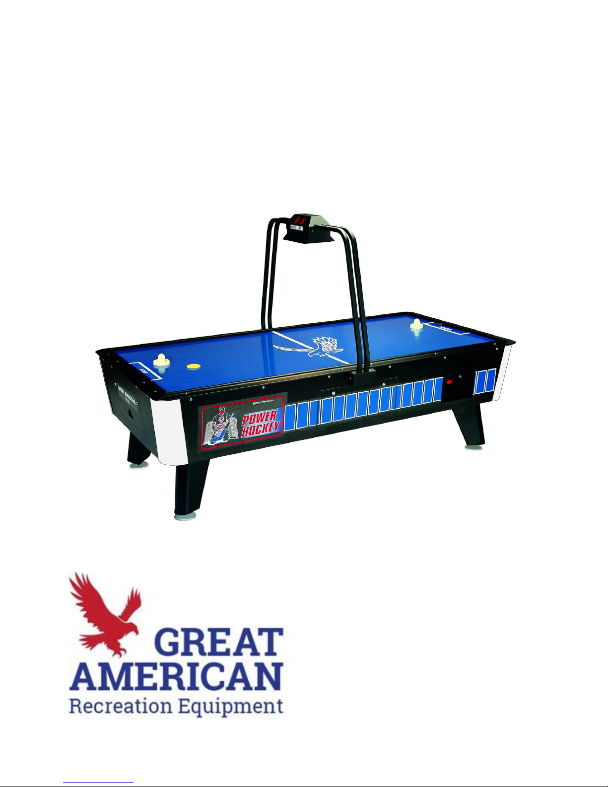
Power Hockey Overhead
Setup & Assembly Instructions
20 Providence Pike
North Smithfield, RI 02896
800-831-2011 • (f) 401-463-6673
www.GreatAmericanRec.com
games@greatamericanrec.com

Parts List
The following parts should be included with the Power Hockey Table:
4 Legs with attached levelers (In a separate box)
16 1 1/2” x 3/8” #16 bolts (Inside cash box)
10 keys (8 taped to outside of coin mechanism and 2 inside)
2 mallets (Inside leg box)
2 pucks (Inside leg box)
The following parts should be included with the Light Bar:
1 Light Bar with wires
1 Light Bar
1 Score Panel
1 Light Fixture
1 Large Light Bar mount cover
1 Small Light Bar mount cover
12 1 1/2” x 1/4” #20 bolts
4 1/2” x 1/4” #20 bolts
4 1/4” nuts
16 1/4” locking washers
4 1/4” washers
8 5/8” #8 pan head screws
Table Maintenance
This is a commercial table and meant for heavy-duty use so very little table maintenance
is required. One thing that should be done every now & then (depending on the use of
your table) is to wipe down the playing surface with a laminate polish. We use a product
called “Countertop Magic” and can be purchased at any Home Depot or comparable
hardware store. Simply turn on the blower motor, spray the laminate polish onto a cloth
and wipe the playing surface
Setup Instructions
1. Locate keys taped to coin mechanism (or inside puck drop if non coin).
2. Remove 4 legs with levelers, and a bag of (16) bolts.
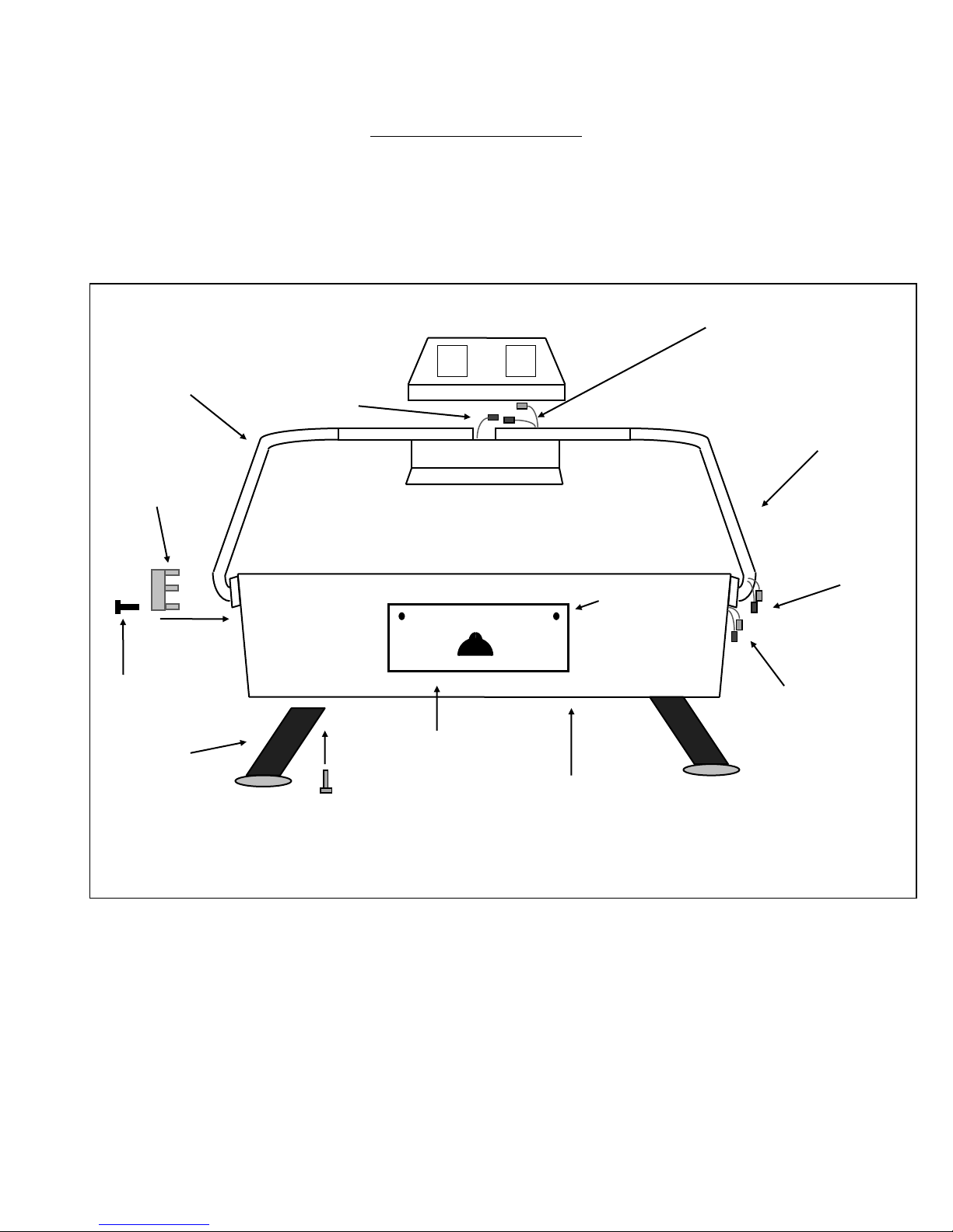
3. Attach legs to bottom of table using (16) 1 1/4” x 3/8” #16 bolts. (See figure 1)
4. Stand table upright.
5. Attach Light Bar as instructed in the next section.
Front View of Power Hockey Table
Figure 1
5/8” #8 pan head screw
Small Light Bar
Mount Cover
Locks
Puck Drop Access Door
Legs
1 1/4” x 3/8” #16 Bolt
Light Bar
Light Bar w/wires
Wires from table
(3 Harnesses)
Wires from Light
Bar (3 Harnesses)
Connects to Score Panel
Wires for Light
Trap door for legs
(on bottom of table)
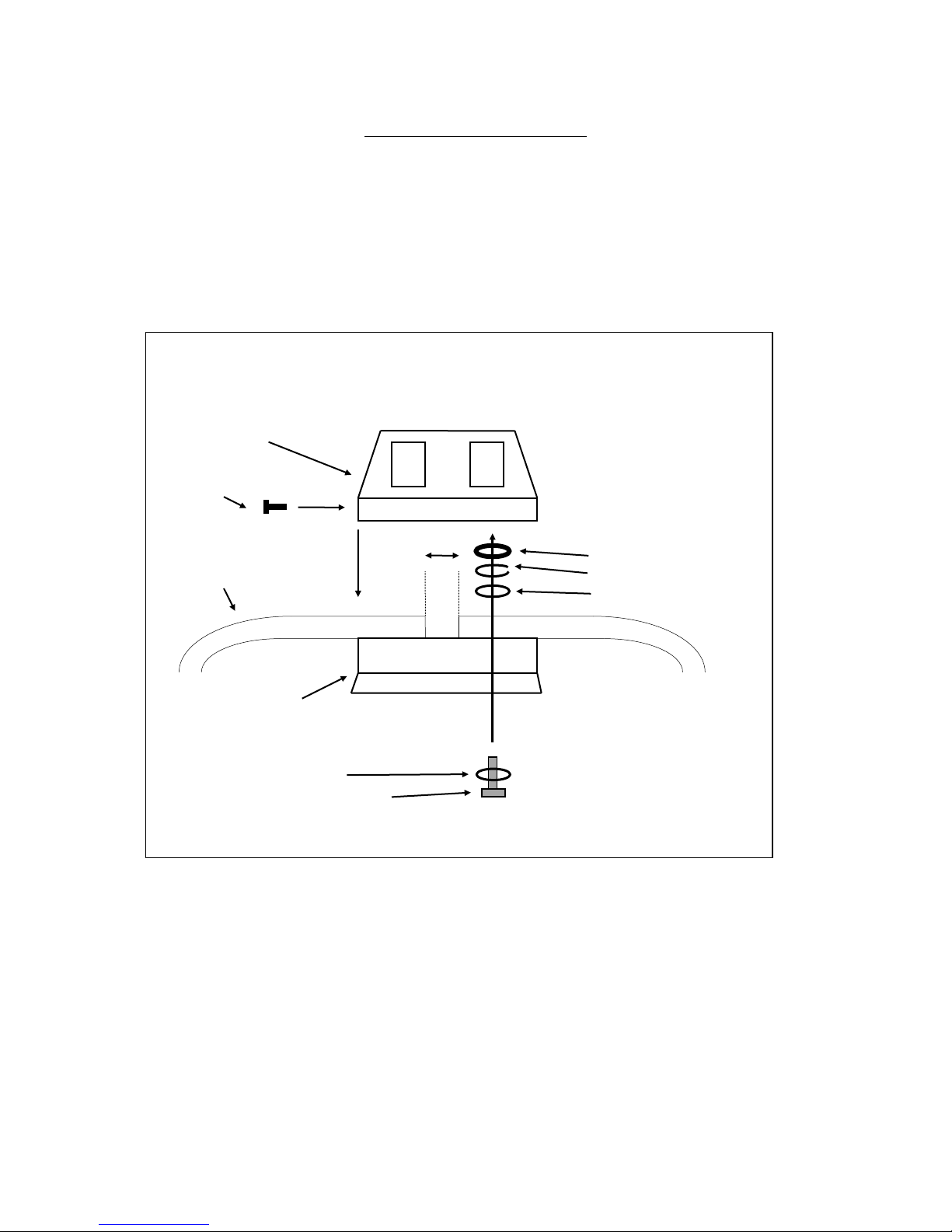
Light Bar Assembly
1. Locate string taped to the side of the Power Hockey table.
2. Remove tape and pull out wire harnesses attached to the string.
3. Attach Light Bar with wire to the side on the table with exposed wire harnesses, using
(6) 1 1/2” x 1/4” #20 bolts and 6 locking washers.
4. Attach remaining Light Bar to the other side of the table in the same way.
5. Attach Light Fixture to the Light Bars using: (4) 1/4” x 1/4” #20 bolts, (8) 1/4” washers,
(4) 1/4” locking washers, and (4) 1/4” nuts. (See figure 2)
6. Connect wires from Light Fixture (2 pin connector) to matching connector in Light Bar.
7. Attach 25 pin harness from light bar to the Score Panel at connector marked
“INTERFACE”. NOTE: Make sure the notches on the harness face center of the
circuit board when you attach it to the board.
8. Screw score panel to the light assembly with (4) 5/8” #8 pan head screws.
9. Connect three wire harnesses to their mates at the base of the light bar.
10. Attach Large Light Bar Mount Cover at the base of the Light Bar with the wires using
(2) 5/8” #8 pan head screws.
11. Attach the Small Light Bar Mount Cover on the opposite side.
FIGURE 2
Score Panel
5/8” pan head screw
1/4” nut
Light Bar 1” 1/4” locking washer
1/4” washer
Light Fixture
1/4” washer
1/2” x 1/4” #20 bolt
 Loading...