

Page 1
EN
ES
FR
DE
IT
NL
PT
HIM HPM .19
Page 2

Page 3

INDEX FOR DIFFERENT LANGUAGES
CO2 Regulation (EU).........................................................1~7
SAFETY INSTRUCTION.......................................................8~14
English manual………………………………........…………..............15~31
Manual en Español ………………………………........……............32~48
Notice en Français………………………………..………..….............49~65
Deutsches Handbuch……………………………..………............….66~81
Manuale Italiano…………………………...................................82~98
Manual Português…………………….................……….............99~115
Netherland manual..........................................................116~133
Page 4
1
Regulation (EU) n° 517/2014 of 16/04/14 on fluorinated greenhouse gases and repealing Regulation (EC) n°
1.
Operators of equipment that contains fluorinated greenhouses gases in quantities of 5 tons of CO2, equivalent or more
2.
For equipment that contains fluorinated greenhouse gases in quantities of 5 tons of CO2 equivalent or more, but of
Load and Tons amounting CO
2
Frequency of test
From 7 at 75 kg load = from 5 at 50 Tons
Each year
1.
Operators of equipment which is required to be checked for leaks, shall establish and maintain records for each piece
a)
The quantity and type of fluorinated greenhouse gases installed;
b)
The quantities of fluorinated greenhouse gases added during installation, maintenance or servicing or due to leakage;
c)
Whether the quantities of installed fluorinated greenhouse gases have been recycled or reclaimed, including the name
d)
The quantity of fluorinated greenhouse gases recovered
e)
The identity of the undertaking which installed, serviced, maintained and where applicable repaired or decommissioned
f)
The dates and results of the checks carried out;
g)
If the equipment was decommissioned, the measures taken to recover and dispose of the fluorinated greenhouse
2.
The operator shall keep the records for at least five years, undertakings carrying out the activities for operators shall
Do no release R32 coolant liquid into the atmosphere. This is a fluoride greenhouse effect gas covered by the
Kyoto agreement with a global warming potencial (GWP) = 675 - (see the European Community regulations
on fluoride greenhouse effect gases Regulation (EU) No 517/2014).
842/2006
Leak checks
and not contained in foams shall ensure that the equipment is checked for leaks.
less than 50 tons of CO2equivalent: at least every 12 months.
Picture of the equivalence CO
Load in kg and Tons amounting CO2.
1.
Concerning the Gas R32, 7.40kg amounting at 5 tons of CO2, commitment to check each year.
2
Training and certification
1. The operator of the relevant application shall ensure that the relevant personnel have obtained the necessary
certification, which implies appropriate knowledge of the applicable regulations and standards as well as the necessary
competence in emission prevention and recovery of fluorinated greenhouse gases and handling safety the relevant type
and size of equipment.
Record keeping
of such equipment specifying the followinginformation:
and address of the recycling or reclamation facility and, where applicable, the certificate number;
the equipment, including, where applicable, the number of its certificate;
gases.
keep copies of the records for at least five years.
Page 5
2
Reglamento (EU) n ° 517/2014 del 16/04/14 sobre gases fluorados de efecto invernadero y anulación del
1.
Los propietarios o mantenedores de equipos que contengan gases invernaderos fluorados en cantidades de 5
2.
Para equipos que contengan gases fluorados de efecto invernadero en cantidades de 5 toneladas de CO2 equivalente o
Carga y toneladas de CO2
Frecuencia de la prueba
De 7 a 75 kg carga = de 5 a 50 Toneladas
Cada año
1.
El personal de mantenimiento que requiera verificar fugas deberán establecer y mantener registros para cada pieza de
B)
La cantidad de gases fluorados de efecto invernadero añadidas durante la instalación, el mantenimiento o el servicio o
C)
si se han reciclado o recuperado la cantidad de gases fluorados de efecto invernadero instalados, incluido el nombre y
D)
La cantidad de gases fluorados de efecto invernadero recuperados
E)
La identidad de la empresa instaladora, reparadora, mantenedora y, en su caso, la empresa desmanteladora del equipo,
F)
Las fechas y resultados de los controles efectuados;
G)
Si el equipo fuera desmantelado, las medidas adoptadas para recuperar y tratar de los gases fluorados de efecto
2.
El operador debe conservar los registros durante al menos cinco años, las empresas que realicen las actividades de los
No expulsar R32 a la atmósfera. Este líquido es un gas fluorado de efecto invernadero cubierto por el
protocolo de Kyoto, con un potencial de calentamiento global (GWP) = 675 - (consulte la normativa de la
Comunidad Europea sobre el Reglamento de gases fluorados de efecto invernadero, (UE - 517/2014).
Reglamento (CE) n ° 842/2006
Inspección de fugas
toneladas de CO2, equivalentes o más y no contenidas en espumas deberán asegurarse de que el equipo se ha
comprobado si tiene fugas.
más, pero de menos de 50 toneladas de CO2 equivalente: Revisar al menos cada 12 meses.
Equivalencia de CO2
1. Carga en kg y toneladas de CO2.
En cuanto al Gas R32, 7.40kg con un valor de 5 toneladas de CO2, se compromete a revisarlo cada año.
Mantenedor Certificado
1. El propietario o mantenedor debe garantizar que el personal pertinente haya obtenido la certificación necesaria, lo que
implica un conocimiento adecuado de las normas y reglamentaciones aplicables, así como la competencia necesaria en
materia de prevención de emisiones y recuperación de gases fluorados tipo y tamaño del equipo.
Mantenimiento de registros
dicho equipo, especificando la siguienteinformación:
A)La cantidad y el tipo de gases fluorados de efecto invernadero instalados;
debido a fugas;
la dirección de la instalación de reciclado o de regeneración y, en su caso, el número del certificado;
incluido, en su caso, el número de su certificado;
invernadero
operadores deben conservar las copias de los registros durante al menos cinco años.
Page 6
3
Règlement (EU) n° 517/2014 du 16/04/14 relatif aux gaz à effet de serre fluorés et abrogeant le règlement
1.
Les exploitants d’équipements qui contiennent des gaz à effet de serre fluorés dans des quantités supérieures ou
2.
Au 1 janvier 2017 les contrôles d’étanchéité sont à effectuer au moins tous les douze mois, pour les équipements dans
Charge et Tonnes équivalant CO2
Fréquence du contrôle
De 7 à 75 kg de charge soit de 5 à 50 Tonnes
Tous les ans
1.
Les exploitants d’équipements qui doivent faire l’objet d’un contrôle d’étanchéité établissent et tiennent à jour, pour
a)
La quantité et le type de gaz à effet de serre fluorés installées,
b)
Les quantités de gaz ajoutées pendant l’installation, la maintenance ou l’entretien ou à cause d’une fuite,
c)
La quantité de gaz installés qui a été éventuellement recyclée ou régénérée, y compris le nom et l’adresse de
d)
La quantité de gaz récupérée,
e)
L’identité de l’entreprise qui a assuré l’installation, l’entretien, la maintenance et, le cas échéant, la réparation ou la
f)
Les dates et les résultats des contrôles effectués,
g)
Si l’équipement a été mis hors service, les mesures prises pour récupérer et éliminer les gaz.
2.
Les exploitants conservent les registres visés audit paragraphe pendant au moins cinq ans, les entreprises exécutant les
Il est interdit de rejeter le gaz R32 dans l’atmosphère. Ce gaz à effet de serre fluorés est régulé par les accords
de Kyoto, son impact est en (GWP) = 675 - (Se référer au règlement de la communauté européenne relatif
aux gaz à effet de serre fluorés, règlement (EU) No 517/2014).
(CE) n° 842/2006
Contrôles d’étanchéité
égales à 5 tonnes équivalent CO2, veillent à ce que ces équipements fassent l’objet de contrôles d’étanchéité.
des quantités supérieures ou égales à 5 tonnes équivalent CO2mais inférieures à 50 tonnes équivalent CO
Tableau des équivalences CO
1. Charge en kg et Tonnes équivalant CO
Pour le Gaz R32, 7.40kg équivalences à 5 tonnes de CO2 donc devoir de vérifier tous les ans.
2
.
2
2.
Formation et certification
1. L'exploitant veille à ce que le personnel concerné ait obtenu la certification nécessaire, qui implique une connaissance
appropriée des règlements et des normes applicables ainsi que la compétence nécessaire en termes de prévention
d'émission, de récupération des gaz à effet de serre fluorés, de manipulation sans danger pour les contrôles d’étanchéité
de l’équipement.
Tenue de registres
chaque pièce de ces équipements, des registres dans lesquels ils consignent les informations suivantes :
l’installation de recyclage ou de régénération et, le cas échéant, le numéro de certificat,
mise hors service de l’équipement, y compris, le cas échéant, le numéro de son certificat,
activités pour le compte des exploitants conservent des copies des registres visés au paragraphe 1 pendant au moins cinq
ans.
Page 7
4
Verordnung (EU) Nr. 517/2014 vom 16/04/14 über fluorierte Treibhausgase und die Verordnung (EG) zur
1.
Die Betreiber von den Geräte, die die fluorierte Treibhausgase in Mengen von 5 Tonnen CO2-Äquivalent oder mehr
2. Für die Geräte, die fluorierte Treibhausgase in Mengen von 5 Tonnen 5 Tonnen CO2-Äquivalent oder mehr enthalten
Belastung und Tonnen von CO2
Häufigkeit der Prüfung
Von 7 bei 75 kg Belastung = von 5 bei 50 Tonnen
Jedes Jahr
1.
Die Betreiber von den Geräte, die auf Dichtheit überprüft werden müssen, müssen für jedes Gerät, das die folgenden
a)
Die Menge und Art der installierten fluorierten Treibhausgase;
b)
Die Mengen an fluorierten Treibhausgasen, die während der Installation, Wartung oder Service oder aufgrund von
c)
Ob die Mengen der installierten fluorierten Treibhausgase wiederverwandt oder zurückgefordert wurden,
d)
Die Menge der fluorierten Treibhausgase wiederhergestellt wird;
e)
Die Identität des Unternehmens, das die Ausrüstung installiert, gewartet und gegebenenfalls repariert oder außer
f)
Datum und Ergebnisse der Prüfung durchgeführt werden;
g)
Wenn das Gerät außer Betrieb hat, wurden die Maßnahmen zur Rückgewinnung und Beseitigung der fluorierten
2.
Die Betreiber bewahrendie Aufzeichnungen für mindestens fünf Jahre lang auf, wobei die Unternehmen, die die
Lassen Sie keine R32-Kühlflüssigkeit in die Atmosphäre gelangen. Dies ist ein Fluorid-Treibhauseffektgas, das
unter das Kyoto-Abkommen fällt, mit einem Potenzial für die globale Erwärmung (GWP) = 675 - (siehe
Verordnung der Europäischen Gemeinschaft zu Fluorid-Treibhauseffekt-Verordnung (EU) Nr. 517/2014).
Aufhebung Nr. 842/2006
Dichtheitsprüfung
enthalten und nicht in Schäumen enthalten, müssen sicherstellen, dass das Gerät auf Dichtheit überprüft wird.
aber weniger als 50 Tonnen CO2-Äquivalent enthalten: mindestens alle 12 Monate.
Bild der Gleichwertigkeit CO
In Bezug auf die Gas R32, 7.40kg in Höhe von 5 Tonnen CO2, Engagement für die Überprüfung jedes Jahr.
2
Ausbildung und Zertifizierung
1. Die Betreiber der betreffenden Anwendung sollen dafür Sorge tragen, dass die zuständige Person die erforderliche
Zertifizierung erlangt hat, die die angemessene Kenntnisse der geltenden Vorschriften und Normen sowie die notwendige
Kompetenz in Bezug auf die Emissionsvermeidung und - verwertung von fluorierten Treibhausgasen und der
Handhabungssicherheit der betreffenden Typen und Größe der Ausrüstung beinhaltet.
Aufbewahrung der Aufzeichnungen
Angaben enthält, Aufzeichnungen erstellen und verwalten:
Leckagen hinzugefügtwerden;
einschließlich der Name und Anschrift der Wiederverwendung oder Rückgewinnungsanlage und gegebenenfalls der
Bescheinigungsnummer;
Betrieb hat, gegebenenfalls einschließlich der Nummer des Zertifikats;
Treibhausgase getroffen.
Tätigkeiten für die Betreiber ausführen, die Aufzeichnungen für mindestens fünf Jahre lang aufbewahren soll.
Page 8
5
Regulamento (EU) n ° 517/2014 de 16/04/14 relativo aos gases fluorados com efeito de estufa e revoga o
Carga e Toneladas em CO2
Frequência de ensaio
De 7 a 75 kg carga = de 5 a 50 Toneladas
por ano
Non rilasciare liquido refrigerante R32 nell'atmosfera.Si tratta di un gas fluorurato a effetto serra coperto
dall'accordo di Kyoto con un potenziale di riscaldamento globale (GWP) = 675 - (cfr. La normativa
comunitaria sul regolamento sui gas fluorurati ad effetto serra (UE) n. 517/2014).
Regulamento (EC) n ° 842/2006
Verificações de vazamento
1. Os operadoresde equipamento que contemgasesfluorados com efeitode estufa em quantidades de 5 toneladasde CO2,
equivalentes ou superiorese não contidosem espumasdevemassegurarque o equipamento é verificadoquanto a fugas.
2. Para equipamentos que contêm gases fluorados com efeito de estufa em quantidades equivalentes ou superiores a 5
toneladas de CO2, mas inferiores a 50 toneladas de CO2 equivalente: pelo menos de 12 em 12 meses.
Imagem da equivalência CO2
1. Carga em kg e toneladas de CO2.
Relativamente ao Gas R32, 7,4kg no montante de 5 toneladas de CO2, deve ser verificado por cada ano.
Treinamento e certificação
1. O operador do pedido relativo deve assegurar que o pessoal relativo tem obtido a certificação necessária, o que implica
um conhecimento adequado dos regulamentos e normas aplicáveis, bem como a competência necessária em prevenção de
emissões e recuperação de gases fluorados com efeito de estufa e tratando seguramente do tipo e tamanho relevante do
equipamento.
Conservação de registros
1. Os operadores de equipamento o qual deve ser verificado quanto a fugas devem estabelecer e manter os registos para
cada peça deste tipo de equipamento, especificando as seguintes informações:
a) A quantidade e o tipo de gases fluorados com efeito de estufa instalados;
b) As quantidades de gases fluorados com efeito de estufa adicionadas durante a instalação ou a manutenção ou devido a
fugas;
c) Se os gases fluorados com efeito de estufa instalados de grandes quantidades foram reciclados ou recuperados,
incluindo o nome e o endereço do dispositivo de reciclagem e recuperação e, se for aplicável, o número do certificado;
d) A quantidade de gases fluorados com efeito de estufa recuperados
e) A identidade da empresa que instalou, manteve e, se for o caso, reparou ou desmantelou o equipamento, incluindo, se
for aplicável, o número do seu certificado;
;
f) As datas e os resultados das verificações efectuadas;
g) As medidas tomadas para recuperar e tratar dos gases fluorados com efeito de estufa se o equipamento foi
desmantelado.
2. O operador deve conservar os registos por pelo menos cinco anos, as empresas que exercem as actividades para
operadores devem conservar as cópias dos registos por pelo menos cinco anos.
Page 9
6
Regolamento (EU) n ° 517/2014 del 16/04/14 sui gas serra fluorurati ad effetto serra e che abroga il
1.
Gli operatori delle apparecchiature che contengono gas fluorurati ad effetto serra con quantità di 5 tonnellate di CO2,
2.
Per le apparecchiature che contengono gas fluorurati ad effetto serra con quantità di 5 tonnellate di CO2 equivalente o
Caricare il totale CO2 in chili e tonnellate
Frequenza di test
Dal 7 a 75 chili di carico = dal 5 a 50 tonnellate
Annuale
1.
Gli operatori di attrezzatura che è necessario per controllare la presenza di perdite, deve stabilire e mantenere i record
a)
La quantità e il tipo di gas fluorurati ad effetto serra installati;
b)
Le quantità di gas fluorurati ad effetto serra aggiunte durante l'installazione, manutenzione o assistenza o a causa di
c)
Se la quantità di gas fluorurati ad effetto serra installate sono state riciclate e rigenerate, insieme al nome e l'indirizzo
d)
la quantità di gas fluorurati ad effetto serra recuperata
e)
L'identità dell'impresa che ha installato, servito, manutenuto e, se del caso riparato o decommissionato le attrezzature,
f)
Le date ei risultati dei controlli effettuati;
g)
Se l'apparecchiatura è stata decommissionata, le misure adottate per recuperare e sistemare i gas fluorurati ad effetto.
2.
L'operatore deve conservare i registri per almeno cinque anni, le imprese che svolgono le attività per gli operatori
Non permettere che il refrigerante R32 entri nell'atmosfera. Si tratta di un gas fluorurato ad effetto serra
coperto dall'accordo di Kyoto, con potenziale di riscaldamento globale (GWP) = 675 - (cfr. Regolamento della
Comunità europea sul regolamento sui fluoro in serra (UE) n. 517/2014).
regolamento (CE) n ° 842/2006
controlli di perdite
equivalenti o superiore e non contiene nelle schiume, devono garantire che il materiale sia stato verificato la presenza di
perdite.
superiore, ma inferiore a 50 tonnellate di CO2 equivalente: controllare almeno ogni 12 mesi.
Immagine del CO2 dell'equivalenza
Per quanto riguarda la Gas R32, 7.40 chili pari a 5 tonnellate di CO2, l'obbligo a controllare ogni anno.
Formazione e certificazione
1. Il gestore della relativa domanda deve assicurare che il personale interessato abbia ottenuto la certificazione
necessaria, che implica una conoscenza appropriata dei regolamenti e delle norme vigenti, nonché la necessaria
competenza in materia di prevenzione delle emissioni e di recupero dei gas fluorurati ad effetto serra e la sicurezza la
gestione dell'apparecchiatura del relativo tipo e dimensioni.
Conservazione di registri
per ogni pezzo di tali attrezzature specificando le seguenti informazioni:
perdite;
del centro di riciclaggio o recupero e, se del caso, il numero del certificato;
include, se del caso, il numero del propriocertificato;
devono tenere copie dei registri per almeno cinque anni.
Page 10
7
Verordening (EU) nr. 517/2014 van het Europees Parlement en de Raad van 16 april 2014 betreffende
1.
Exploitanten van apparatuur die gefluoreerde broeikasgassen in hoeveelheden van 5 ton CO2, zelfde aantal of meer
2.
Voor apparatuur die gefluoreerde broeikasgassen in hoeveelheden van 5 ton CO2 zelfde aantal of meer bevatten,
Lading en Ton van hoeveelheid CO
2
Testfrequentie
Van 7 tot 75 kg lading = van 5 tot 50 Ton
Ieder jaar
1.
Exploitanten van apparatuur die verplicht zijn op lekkage te controleren, zullen registers aanmaken en bijhouden
a)
De hoeveelheid en het type van de geïnstalleerde gefluoreerde broeikasgassen;
b)
De hoeveelheden gefluoreerde broeikasgassen toegevoegd tijdens het installeren, onderhoud of de service of als
c)
Of de hoeveelheden van de geïnstalleerde gefluoreerde broeikasgassen zijn gerecycleerd of teruggewonnen, inclusief
d)
De hoeveelheid teruggewonnen gefluoreerde broeikasgassen
e)
De identiteit van de onderneming die de installatie, reparatie, onderhoud uitvoert en voor zover van toepassing
f)
De data en de resultaten van de verrichte controles;
g)
Indien de apparatuur buitengebruik werd gesteld, de genomen maatregelen voor het terugwinnen en afvoeren van de
2.
De exploitant zal de administratie gedurende tenminste vijf jaar bewaren, de ondernemingen die de werkzaamheden
Laat R32-koelvloeistof niet in de atmosfeer ontsnappen. Dit is een gas van het broeikaseffect met fluor dat
onder de Kyoto-overeenkomst valt met een broeikas effect (GWP) = 675 - (zie de Europese
Gemeenschapswetgeving inzake broeikasgassen met fluoride-verordening (EU) nr. 517/2014).
gefluoreerde broeikasgassen en tot intrekking van Verordening (EC) nr. 842/2006
Controle op lekkages
bevatten en niet verpakt in het isolatieschuim dragen er zorg voor dat de apparatuur wordt gecontroleerd op lekken.
maar minder dan 50 ton CO2-equivalent: tenminste iedere 12 maanden.
Beeld van de CO2-equivalent
1. Lading in kg en Ton van hoeveelheid CO2.
Met betrekking tot Gas R32, 7.40kg met de hoeveelheid 5 ton CO2, toewijding aan jaarlijkese controle.
Training en certificatie
1. De exploitant van de betreffende toepassing zal er voor zorg dragen dat het betrokken personeel de nodige
certificering hebben verkregen, hetgeen inhoudt voldoende kennis van de geldende voorschriften en norm te bezitten,
alsmede de nodige deskundigheid in emissiepreventie en terugwinning van gefluoreerde broeikasgassen en hanteren van
de veiligheid van de betreffende type en de omvang van de apparatuur.
Registratie
voor elk deel van dergelijke apparatuur dat de volgende informatie bevat:
gevolg van lekkage;
de naam en het adres van de recycling- of terugwinningsinstallatie en waar van toepassing het certificaatnummer;
raparties of verwijdering van apparatuur voor zijn rekening neemt, inclusief, in voorkomend geval, het nummer van haar
certificaat;
gefluoreerde broeikasgassen.
voor de exploitanten uitvoeren, moeten tenminste vijf jaar kopieën van de registers bijhouden.
Page 11

8
SAFETY INSTRUCTIONS. READ CAREFULLY
• All electrical installations should comply with the following standard;
NF C15-100
NF EN 60-335-2-41
that refers “to the construction of electrical installations, both in indoor and outdoor swimming pools”, or the equivalent standard
in force in each region or country.
• All heat pump should follow the C 15-100 installation standard that stipulates that all electrical apparatus located at less than
3.5 m. from the pool and freely accessible, should be supplied by a very low voltage of 12 V. All apparatus supplied with 220 V
should be located at least 3.5 m. from the swimming pool edge. Ask the manufacturer for permission to make any modifications
in one or more elements of the heat pump system.
• The electrical installation should be performed by professional staff qualified in electrical installations.
• Do not operate the apparatus unless it is properly installed.
• NEVER touch the heat pump when it is operating if you are wet or have wet hands.
• When you want to open the cabinet of heat pump, DISCONNECT the power supply.
• Make sure that the ground is dry before touching the electrical equipment.
• Do not allow children or adults to lean against or sit on the apparatus.
• If the supply flex of the apparatus is damaged, it should be replaced. Read the instructions carefully to replaceit.
If in doubt, contact the technical service.
Page 12

9
INDICACIONES DE SEGURIDAD, LÉALAS ATENTAMENTE
• En todo lo referente a la instalación eléctrica debe seguirse la normativa:
NF C15-100
NF EN 60-335-2-41
que hace referencia “a la construcción de instalaciones eléctricas, tanto en piscinas cubiertas como en piscinas al aire libre”, o
la normativa análoga vigente en cada zona o país.
•”Todas las bomba de calor siguen la norma de instalación C 15-100 que especifica que todo aparato eléctrico ubicado a
menos de 3,5 m de la piscina y accesible libremente debe estar alimentado con muy baja tensión 12 V. Todo aparato
alimentado en 220V debe estar ubicado por lo menos a 3,5 m del borde de la piscina Pedir permiso del fabricante para toda
modificación de uno o varios elementos del sistema de bomba de calor.
• La instalación eléctrica debe ser hecha por personal profesional cualificado en instalacioneseléctricas.
• No opere el aparato a menos que esté instalado correctamente
• No toque NUNCA el bomba de calor en marcha con el cuerpo húmedo o las manos húmedas.
• Cuando desee abrir el armario de la bomba de calor, DESCONÉCTELO de la toma de corriente.
• Asegúrese de que el suelo está seco antes de tocar el equipo eléctrico.
• No permita ni a niños ni a adultos apoyarse o sentarse sobre el aparato.
• Si el cable flexible de alimentación de este aparato está dañado, debe ser sustituido. Lea detenidamente las instrucciones
para su sustitución. Ante la duda consulte con un serviciotécnico.
Page 13

10
INDICATIONS DE SÉCURITÉ, LISEZ-LES ATTENTIVEMENT
• Pour tout ce qui concerne l’installation électrique, il faut suivre les normes:
NF C15-100
NF EN 60-335-2-41
qui ont attrait “à la construction d’installations électriques, aussi bien dans des piscines couvertes que dans des piscines en
plein air”, ou les normes analogues en vigueur dans chaque région ou pays.
• “Toutes les pompe à chaleur suivent la norme d'installation NF C 15-100 stipulant que tout appareil électrique situé à moins
de 3,50 m du bassin et librement accessible doit être alimenté en très basse tension 12 V. Tout appareil électrique alimenté en
220 V doit être situé au moins à 3,50 m du bord du bassin. Demander l'avis du fabricant pour toute modification d'un ou
plusieurs éléments du système de la pompe à chaleur”.
• L’installation électrique doit être faite par des professionnels qualifiés en installations électriques.
• N'utilisez pas l'appareil avant qu'il ne soit correctement installé
• Ne touchez JAMAIS la pompe à chaleur en marche si vous avez le corps ou les mains humides.
• Lorsque vous souhaitez ouvrir la pompe à chaleur, DÉBRANCHEZ-LA de la prise de courant.
• Vérifiez que le sol est bien sec avant de toucher l’équipementélectrique.
• Interdisez aux enfants et aux adultes de s’appuyer ou de s’asseoir sur l’appareil.
• Il faut remplacer le câble flexible d’alimentation de cet appareil, s’il est abîmé. Lisez attentivement les instructions pour le
remplacer. Si vous avez un doute quelconque, veuillez consulter un service technique.
Page 14

11
SICHERHEITSHINWEISE, BITTE AUFMERKSAM LESEN+
• Bei der gesamten Installation elektrischer Komponenten muss folgende Norm befolgtwerden:
NF C15-100
NF EN 60-335-2-41
Diese Norm bezieht sich auf “den Aufbau von elektrischen Installationen in Hallenbädern und Freibädern”. Ebenso müssen die
Normen befolgt werden, die in jeder Region oder jedem Land anwendbar sind.
•“Alle die Wärmepumpe entsprechen der Norm für die Installation C 15-100, die angibt, dass alle elektrischen Apparate, die
sich in weniger als 3,5 m Entfernung vom Schwimmbad befinden und frei zugänglich sind, mit einer Niedrigspannung von 12 V
gespeist werden müssen. Alle Apparate, die mit 220 V gespeist werden, müssen sich mindestens 3,5 m vom Rand des
Schwimmbeckens entfernt befinden. Wenn ein oder mehrere Elemente des die Wärmepumpe systems geändert werden
sollen, muss der Hersteller die entsprechende Genehmigung erteilen”
• Die elektrische Installation muss von Fachleuten für elektrische Installationendurchgeführt werden.
• Lassen Sie den Apparat nie laufen, wenn es ordnungsgemäß installiert ist.
• Berühren Sie die Wärmepumpe NIEMALS, wenn Ihr Körper oder Ihre Hände nasssind.
• Wenn Sie das Gehäuse der Wärmepumpe öffnen wollen, schalten Siedie Stromversorgung aus.
• Vergewissern Sie sich, dass der Boden trocken ist, bevor Sie die elektrische Ausrüstung berühren.
• Erlauben Sie nicht, dass sich Kinder oder Erwachsene an den Apparat anlehnen oder auf ihn setzen.
• Wenn das flexible Kabel für den Stromanschluss beschädigt ist, muss es ausgetauscht werden. Lesen Sie
aufmerksam die Anweisungen für den Austausch. Im Zweifelsfalle ist der Kundendienst zu befragen.
Page 15

12
INDICAZIONI DI SICUREZZA, LEGGERE ATTENTAMENTE
• Per quanto riguarda l’installazione elettrica, si renderà necessario adempiere alla seguentenormativa:
NF C15-100
NF EN 60-335-2-41
che si riferisce “alla costruzione di installazioni elettriche, sia per piscine coperte sia per piscine all’aria aperta”, o la normativa
analoga in vigore in ciascuna zona o paese.
• ”Tutti la pompa di calore adempiono alla norma di installazione C 15-100 che specifica che ogni apparecchio elettrico
ubicato a meno di 3,5 m dalla piscina e liberamente accessibile deve essere alimentato con una tensione molto bassa da 12 V.
Ogni apparecchio alimentato a 220 V deve essere ubicato a un minimo di 3,5 m dal bordo della piscina. Si renderà necessario
richiedere l’autorizzazione del fabbricante per qualsiasi modifica di uno o più elementi del sistema di pompa di calore”
• L’installazione elettrica deve essere realizzata da personale professionale qualificato per installazioni elettriche.
• Non utilizzare l'apparecchio se non è installato correttamente
• Non toccare MAI la pompa di calore in marcia con il corpo umido o con le mani umide.
• Quando si desidera aprire il cabinet di pompa di calore, si renderà necessario DISINSERIRLO dalla presa di
corrente.
• Si assicuri che il suolo sia asciutto prima di toccare l’apparecchio elettrico.
• Non consenta né a bambini né a adulti di appoggiarsi o sedersi sull’apparecchio.
• Se il cavo flessibile dell’alimentazione di questo apparecchio è danneggiato, si dovrà procedere alla sua
sostituzione. Legga attentamente le istruzioni per la sostituzione. In caso di dubbi, si rivolga al servizio tecnico.
Page 16

13
INDICAÇÕES DE SEGURANÇA, LEIA COM ATENÇÃO
• No que se refere à instalação eléctrica dever-se-á seguir a norma:
NF C15-100
NF EN 60-335-20-41
relativa “à construção de instalações eléctricas, tanto em piscinas cobertas como em piscinas ao ar livre”, ou a norma análoga
vigente em cada região ou país.
•”Todas as bomba de calor seguem a norma de instalação C 15-100 que especifica que qualquer aparelho eléctrico situado a
menos de 3,5 m da piscina e com livre acesso deve estar alimentado com muito baixa tensão 12 V. Todo aparelho alimentado
com 220 V deve estar situado a, no mínimo, 3,5 m do bordo da piscina. Para qualquer modificação de um ou de vários
elementos do sistema de bomba de calor, deve-se pedir a autorização do fabricante.
• A instalação eléctrica deve ser realizada por profissionais qualificados em instalações eléctricas.
• A bomba de calor pode estar ligada enquanto a piscina está sendousada.
• Não toque NUNCA no bomba de calor em funcionamento com o corpo ou com as mãos húmidas.
• Quando quiser abrir o armário da bomba de calor, DESLIGUE-O da tomada.
• Assegure-se de que o chão esteja seco, antes de tocar no equipamentoeléctrico.
• Não permita que crianças ou adultos se apoiem ou sentem no aparelho.
• Se o cabo de alimentação flexível estiver danificado, deverá ser substituído. Leia com atenção as instruções para a
substituição do cabo. Em caso de dúvida consulte ou serviço técnico.
Page 17

14
DE VEILIGHEIDSAANWIJZINGEN AANDACHTIG DOORNEMEN
Voor alles wat de elektrische installatie betreft moet de norm
EN C15-100
NF EN 60-335-2-41
gevolgd worden die betrekking heeft op “de aanleg van elektrische installaties, zowel voor overdekte zwembaden als voor
openlucht zwembaden”, of de desbetreffende norm van ieder land of regio afzonderlijk.
• Voor alle de warmtepomp moet de installatienorm C15-100 gevolgd worden die duidelijk specificeert dat ieder willekeurig
elektrisch apparaat dat zich op minder dan 3.5 m afstand van het zwembad bevindt en waar het publiek vrij toegang toe
heeft, op een laag voltage van 12V werkt. Elk apparaat dat werkt op een voltage van 220V moet op zijn minst op een
afstand van 3,5 m van de rand van het zwembad geplaatst worden. Voor het veranderen van een of meerdere elementen
van het de warmtepomp systeem moet toestemming aan de fabrikant gevraagdworden
• De elektrische installatie moet aangelegd worden door vakmensen, gespecialiseerd in elektrischeinstallaties.
• Gebruik het apparaat niet in werking tenzij het goed is geïnstalleerd.
• NOOIT met een nat lichaam of natte handen het werkende de warmtepomp aanraken.
• Wanneer u de kast van de warmtepomp te openen, koppel de voeding
• Alvorens enig elektrisch toestel aan te raken eerst controleren of de grond droog is.
• Verbied kinderen en volwassenen om op het apparaat te gaan zitten of er tegen aan te leunen.
• Als het buigbare snoer van dit apparaat beschadigd is, moet het vervangen worden. Lees hiertoe aandachtig de
instructies ter vervanging van het snoer. Bij eventuele twijfel de technische dienst raadplegen.
Page 18
15
INDEX
1. Specifications
2. Transport advertising
3. Dimension
4. Installation and connection
5. Electrical wiring
6. Display controlleroperation
7. Troubleshooting
8. Exploded diagram
9. Maintenance
ATTENTION: This manual includes all the necessary information with the use and the installation of your heat
pump.
The installer must read the manual and follow the instructions of implementation and maintenance.
The installer is responsible for the installation of the product and should follow all the instructions of the
manufacturer and the regulations in application. Incorrect installation will invalidate the guarantee.
The manufacturer declines any respectability for the damage caused by any third party, object ingression and of the
errors due to the installation that do not follow the manual guidelines. Any use that is not as intended by the
manufacturer will invalidate the guarantee.
MINI HEATER
User and Service manual
Thank you for using Mini Heater for your pool heating, it will heat your pool water and keep the constant
temperature when the air ambient temperature is above 12 ℃.
Page 19

16
WARNING
- Do not braze or weld the pipe if there is refrigerant inside machine. Please do not charge the gas when in a
- Please always empty the water in heat pump during winter time or when the ambient temperature drops
- Please always cut the power supply if you want to open the cabinet to reach inside the heat pump.
- Please well keep the display controller in a dry area to protect the display controller from being damaged
- Action of filling gas must be conducted by professional with R32 operating license.
- Please always keep the heat pump in a well ventilated place and away from anything which could cause fire.
confined space.
below 0℃, or else the Titanium exchanger will be damaged because of being frozen, in such case, your
warranty will be lost.
by humidity.
Page 20
17
1. Specifications
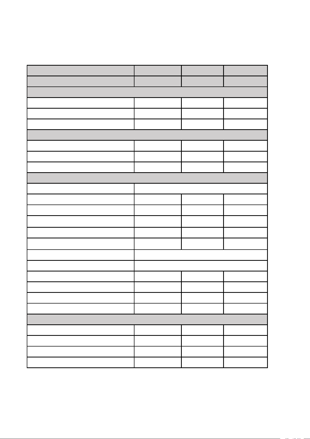
1.1 Technical data pool heat pumps
CE Standard, gas R32.
Item
HPM20
HPM30
HPM40
Code
71245
71258
71606
* Heating Capacity at Air 28℃, Water 28℃, Humidity 80%
Heat Output (kW)
2.5
4.2
5.5
Power Consumption (kW)
0.59
1
1.31
COP
4.2
4.2
4.2
* Heating Capacity at Air 15℃, Water 26℃, Humidity 70%
Heat Output (kW)
1.9
3.2
4.2
Power Consumption (kW)
0.56
0.91
1.2
COP
3.4
3.5
3.5
* General data
Voltage (V)
220-240V~50Hz/1PH
Rated Current (A)
2.6
4.4
5.8
Fuse Current (A)
7.51316
Advised Pool Volume(m3)
0-10
5-16
10-20
Advised water flux (m3/h)
2
2
2.5-3.2
Water Pressure Drop (Kpa)
151515
Condenser
Titanium exchanger in PVC
Water Pipe in-out (mm)
38/32
Fan Speed (rpm)
2500
1100
1100
Noise Level (10m) dB(A)
484646
Noise Level (1m)
575555
Refrigerant Type (R32)
150
290
450
* Dimension/ Weight
Net Weight (kg)
182626
Gross Weight (kg)
19
28.5
28.5
Net Dimension (mm)
310*363.5*375
434*432.5*460
434*432.5*460
Packing Dimension (mm)
365*440*440
485*510*530
485*510*530
* Above data are subjects to modification without notice.
Page 21

18
2. Transport advertising
2.1 Delivery of the packaging
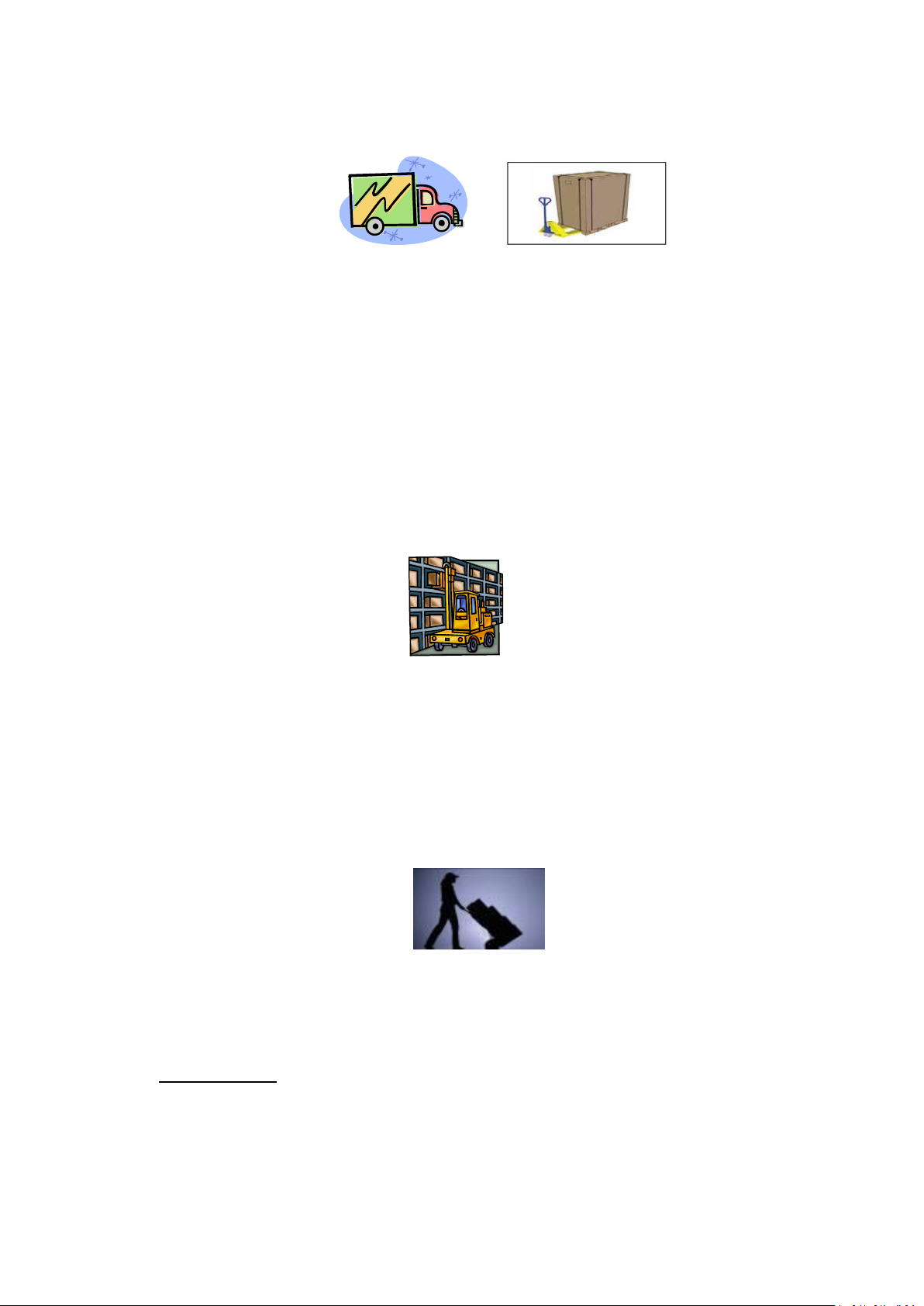
For the transportation, the heat pumps are fixed on the pallet and cover with a cardboard box.
2.2 Stock advertising
* The warehouse should be bright, spacious, open, well ventilated, have ventilation equipment and no
* Heat pump must be stored and transfer in vertical position in its original packaging. If it is not the case, it
2.3 Transferto the final position
* During the unpacking of the product and the transfer from the pallet to the final place of installation, it is
* Smoking and the use of flames are prohibited near R32machine.
To preserve from any damage, the heat pump must be transferred in its package.
It is the responsibility of the addressee to notify of any damage incurred during delivery within
48 hours. No responsibility can be taken once the unit has been signed for.
fire source.
cannot be operated until a minimum period of 24H has passed before the unit can have the electrical power
turned on.
FORBIDDEN
necessary to maintain the heat pump in a vertical position.
Water connection are not to be used as load bearing handles. The manufacturer would not take the
responsibility in case of damage to the water pipes.
Page 22
19
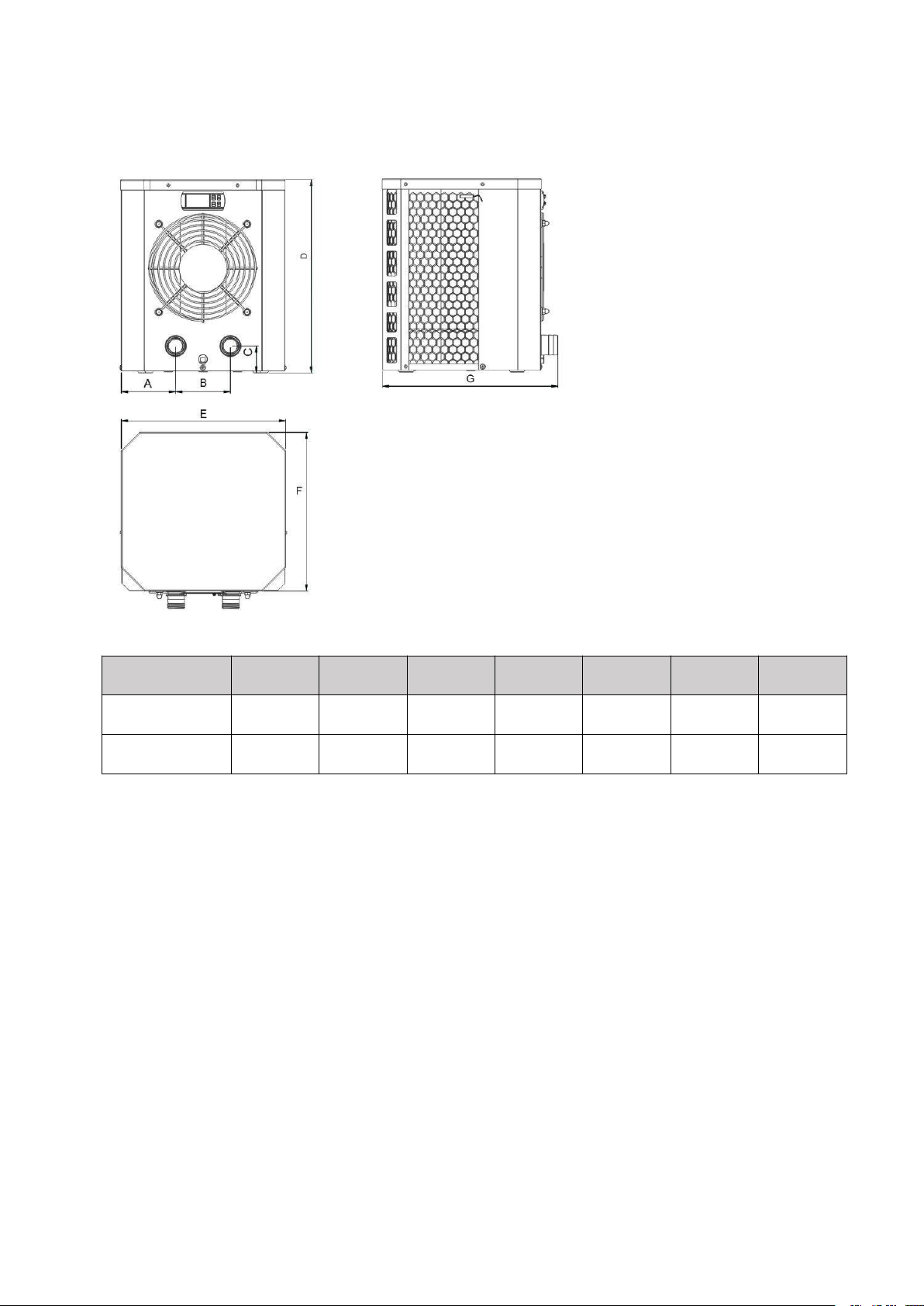
3. Dimension
Item / (mm)
ABCDEFG
HPM20
90.4
13050375
310
300
363.5
HPM30/HPM40
116.5
20050460
434
365
432.5
Page 23
20
4. Installation and connection
Attention:
1. Any addition of chemicals must take place in the piping located downstream from the heat pump.
2. Always hold the heat pump upright. If the unit has been held at an angle, wait at least 24 hours before
applying main power to the heat pump.
4.1 Heat pump location
4.2 Initial operation
Please observe the following rules when installing the heat pump:
The unit will work properly in any desired location as long as the following three items are present:
1. Fresh air – 2. Electricity – 3. Swimming pool filters
The unit may be installed in virtually any outdoor location as long as the specified minimum distances to other
objects are maintained (see drawing below). Please consult your installer for installation with an indoor pool.
Installation in a windy location does not present any problem at all.
ATTENTION: Never install the unit in a closed room with a limited air volume in which the air expelled from the
unit will be reused, or close to shrubbery that could block the air inlet. Such locations impair the continuous
supply of fresh air,resulting in reduced efficiency and possibly preventing sufficient heat output.
Note: In order to heat the water in the pool (or hot tub), the filter pump must be running so the water to is
circulating through the heat pump. The heat pump will not start up if the water is not circulating.
Page 24
21
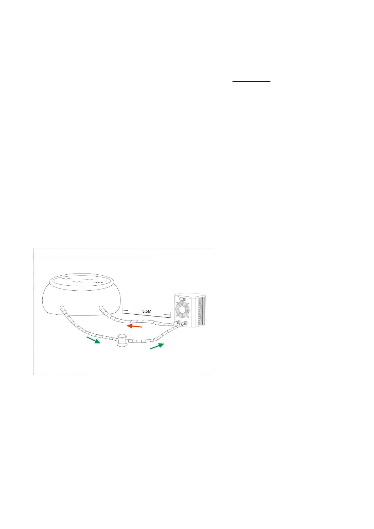
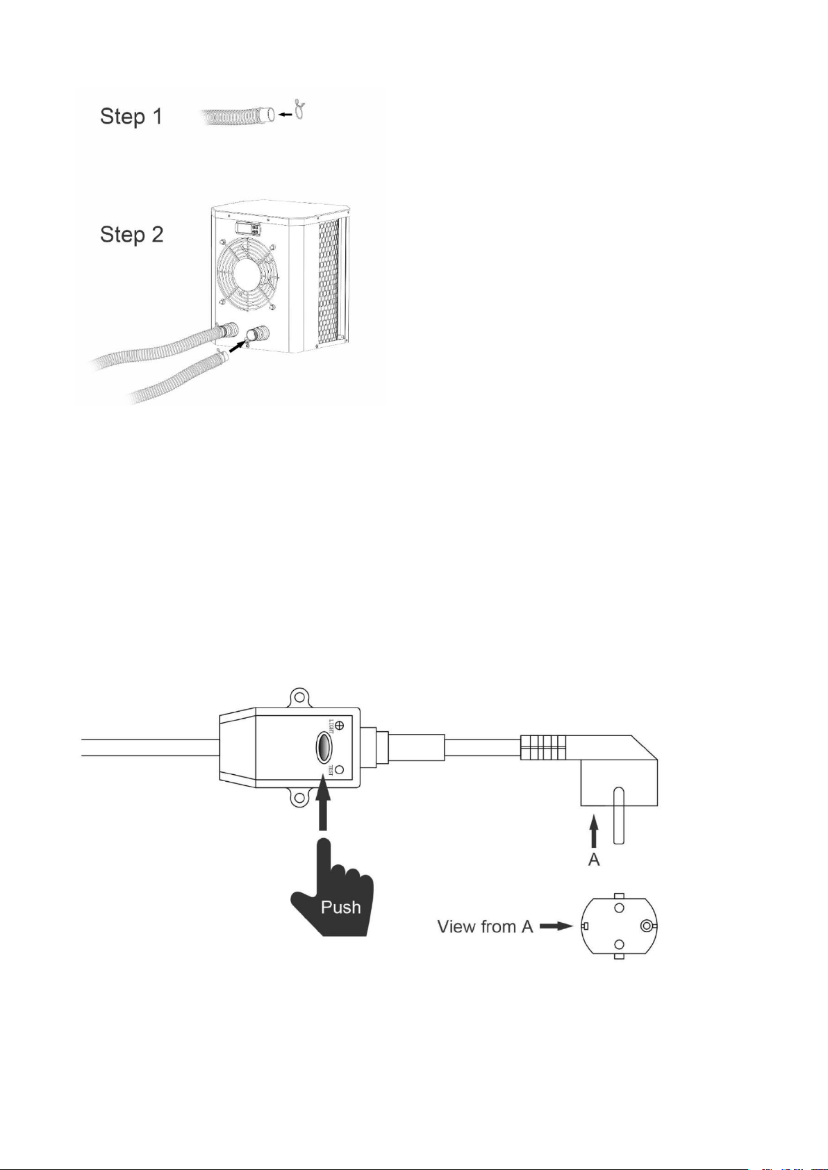
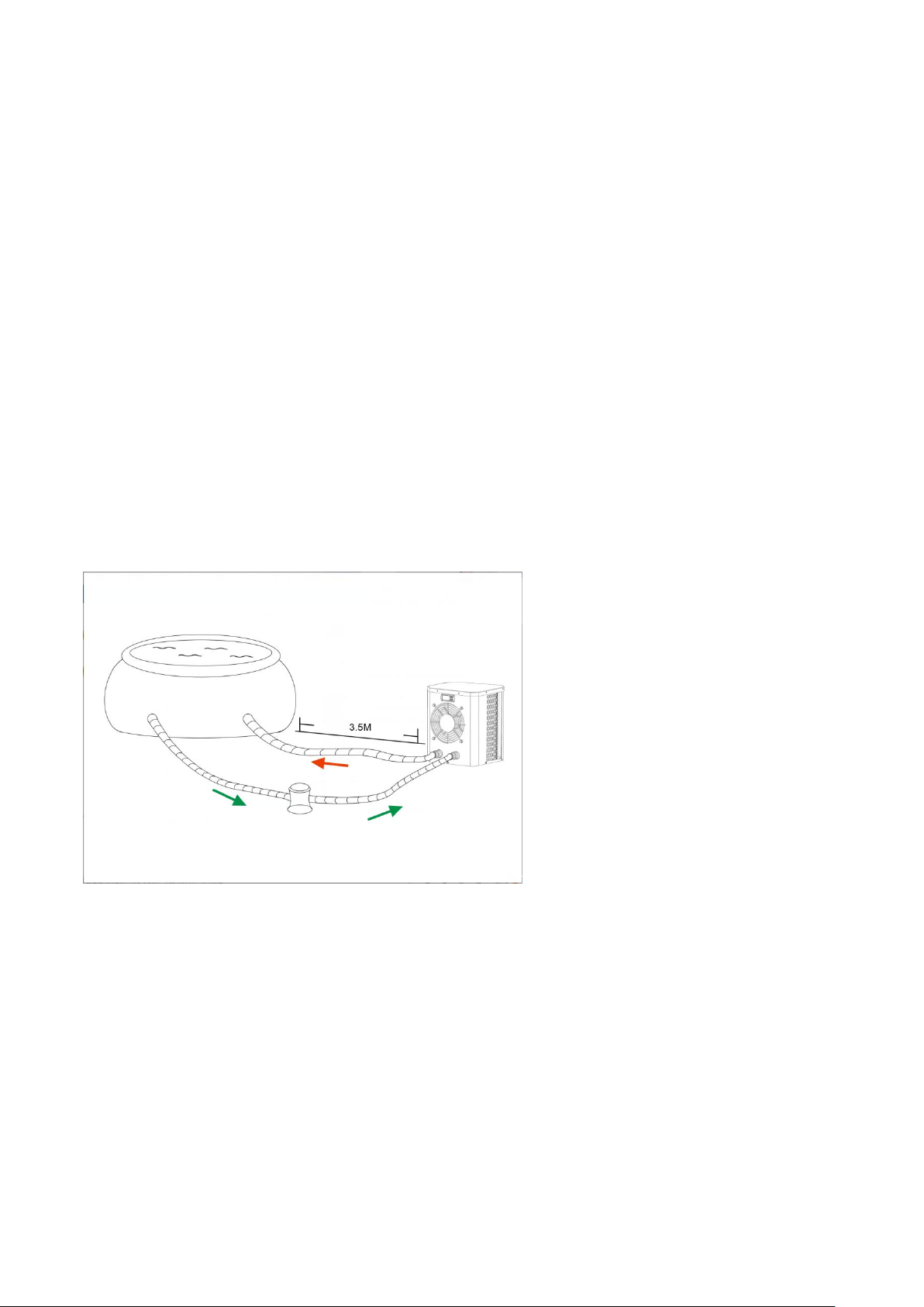
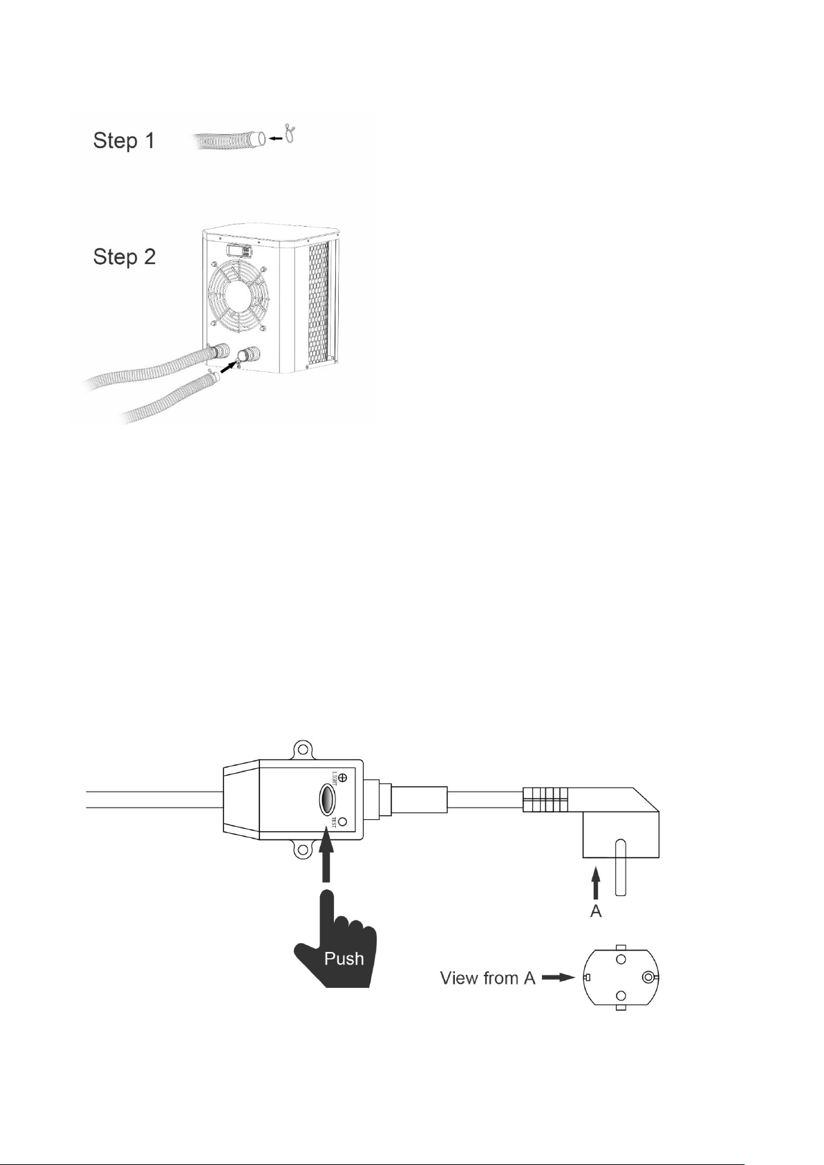
4.3 Hose connection
Note:
The factory supplies only the heat pump. All other components, including two hoses, must be provided by the
user or the installer.
4.4 Electrical connection
Before connecting the unit, verify that the supply voltage matches the operating voltage of the heat pump.
The RCD plug has been included with power cable, which can offer electrical protection.
Page 25
22
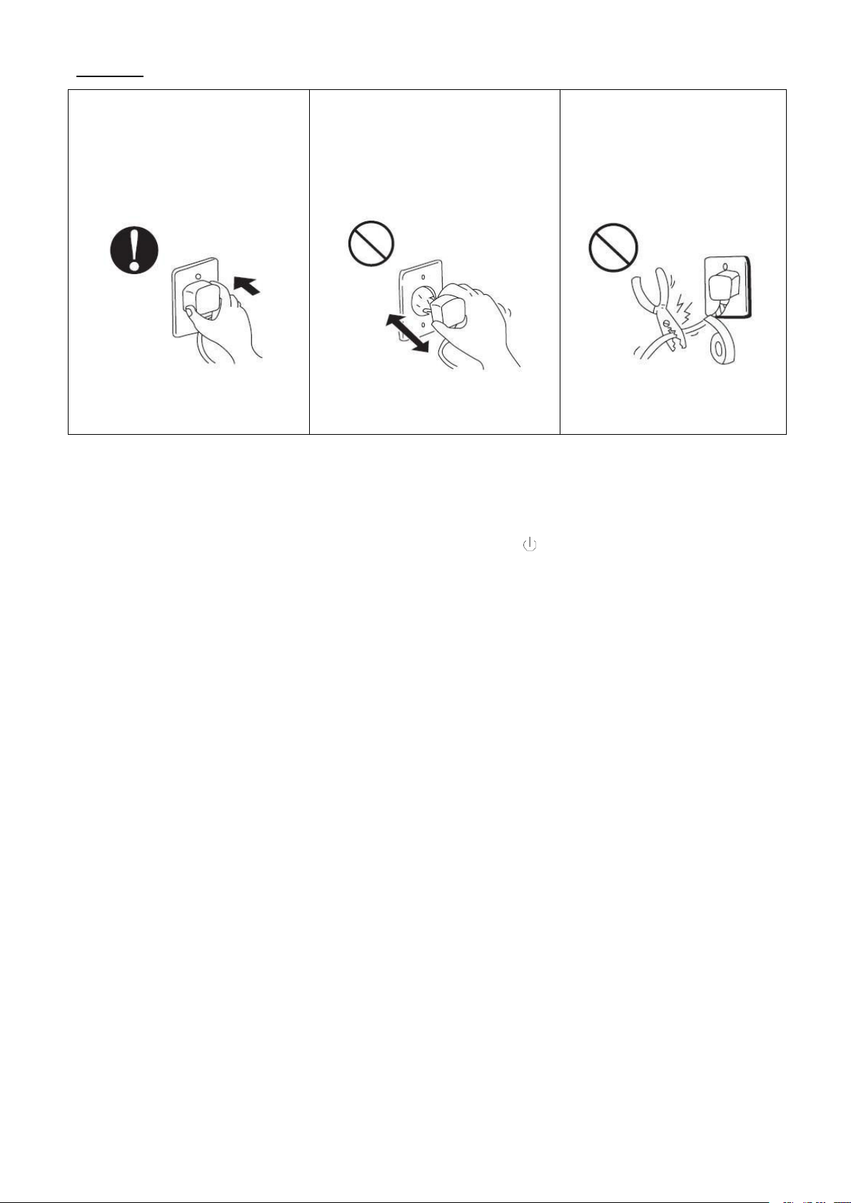
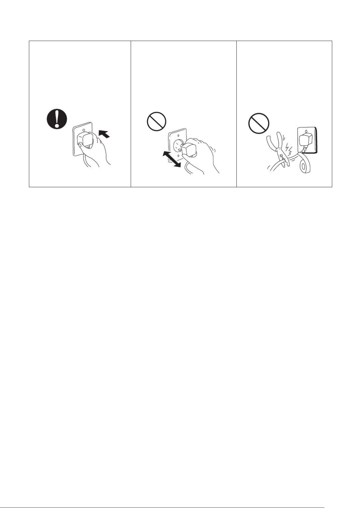
Attention:
Ensure the power plug is secure
Never pull out the power plug during
Never use damaged electric wires
If the plug is not secure, it may cause
operation
or unspecified electric wires.
an electric shock, over-heating or
Otherwise, it may cause an electric
Otherwise it may cause an electric
fire
shock or a fire due to over-heating.
shock or a fire.
1. Switch on the filter pump. Check for leaks and verify that water is flowing from and to the swimming pool.
2. Connect power to the heat pump and press the On/Off button on the electronic control panel. The
3. After a few minutes, check whether the air blowing out of the unit iscooler.
4. When the filter pump is turned off, the unit should also turn off automatically.
5. Allow the heat pump and the filter pump to run 24 hours a day until the desired water temperature is
After all connections have been made and checked, carry out the following procedure:
unit will start up after the time delay expires (see below).
reached. The heat pump will stop running at this point +1ºC. After this, it will restart automatically (as long
as the filter pump is running) whenever the swimming pool water temperature drops 1 degree below the set
temperature (for example, if you sent the temperature 28 ºC, the heat pump will stop when the
temperature at 29ºC. While it will restart when the temperature of the water down to 27ºC).
Depending on the initial temperature of the water in the swimming pool and the air temperature, it may take
several days to heat the water to the desired temperature. A good swimming pool cover can dramatically
reduce the required length of time.
Time delay - The heat pump has a built-in 3-minute start-up delay to protect the circuitry and avoid excessive
electrical contactor wear. The unit will restart automatically after this time delay expires. Even a brief power
interruption will trigger this time delay and prevent the unit from restarting immediately. Additional power
interruptions during this delay period do not affect the 3-minute duration of the delay.
Page 26

23
4.5 Condensation
The air drawn into the heat pump is cooled by the operation of the heat pump for heating the pool water,
which may cause condensation on the fins of the evaporator. The amount of condensation may be as much as
several litters per hour at high humidity. The condensate will drain from the bottom of the heat pump. This is
sometimes mistakenly regarded as a water leak. .
Page 27
24
5. Electrical wiring
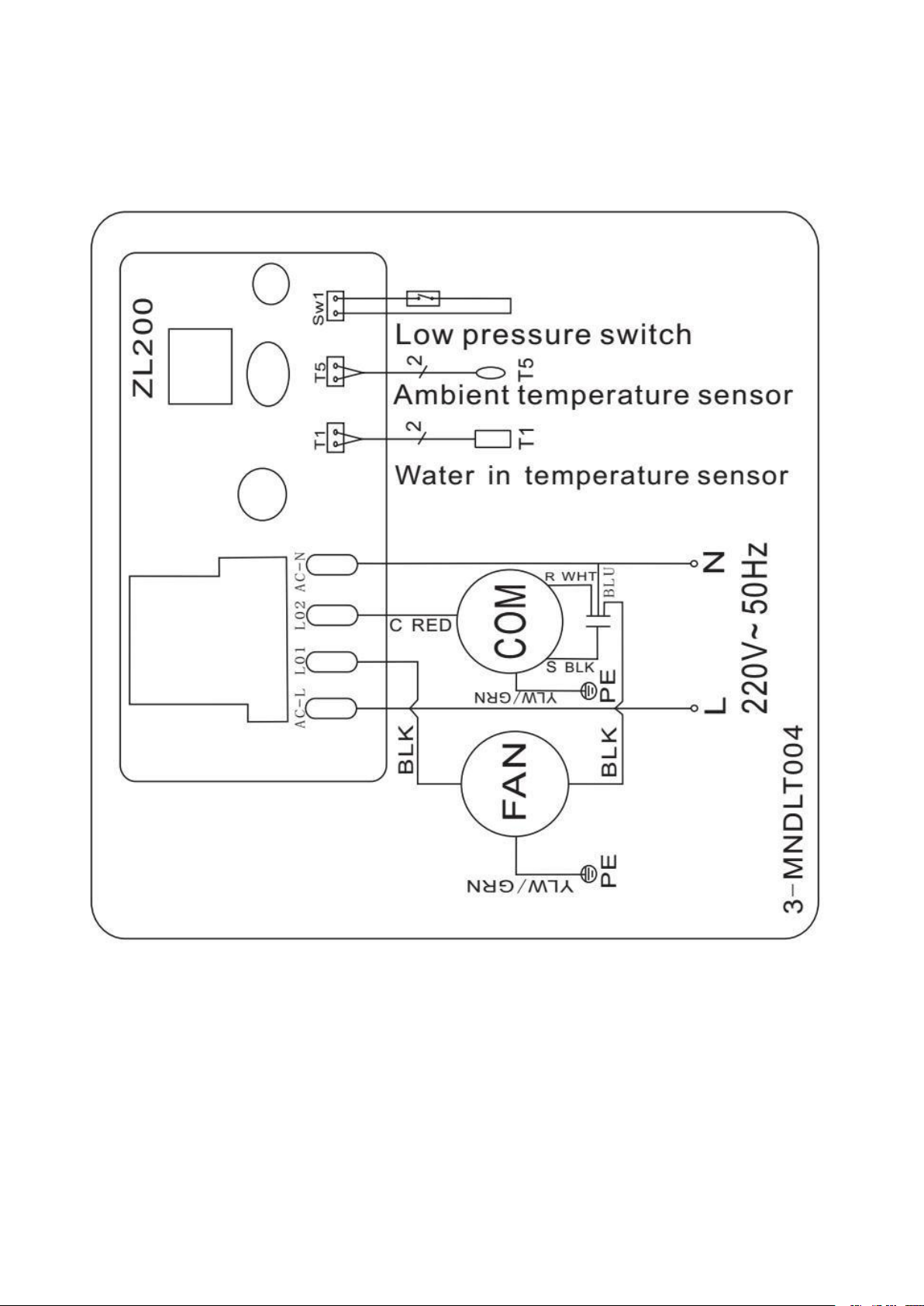
5.1 Swimming pool heat pump wiringdiagram
Code; HPM20
Page 28
25
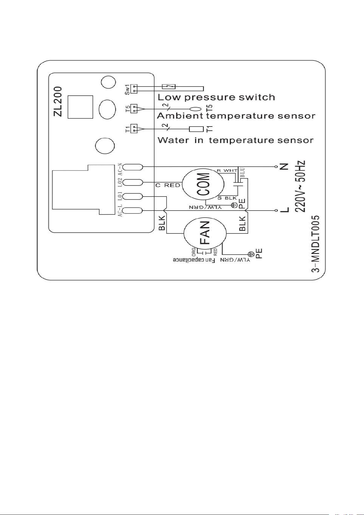
5.2 Swimming pool heat pump wiringdiagram
Code; HPM30/HPM40
(1) Above electrical wiring diagram only for your reference, please subject machine posted the wiring diagram.
(2) The swimming pool heat pump must be connected ground wire, although the unit heat exchanger is
NOTE:
electrically isolated from the rest of the unit. Grounding the unit is still required to protect you against short
circuits inside the unit. Bonding is alsorequired.
Disconnect: A means to disconnect should be located within sight of and readily accessible from the
unit(circuit breaker, fused or un-fused switch). This is common practice on commercial and residential heat
pumps. It prevents remotely-energizing unattended equipment and permits turning off power at the unit
while the unit is being serviced.
Page 29
26
6. Display controlleroperation
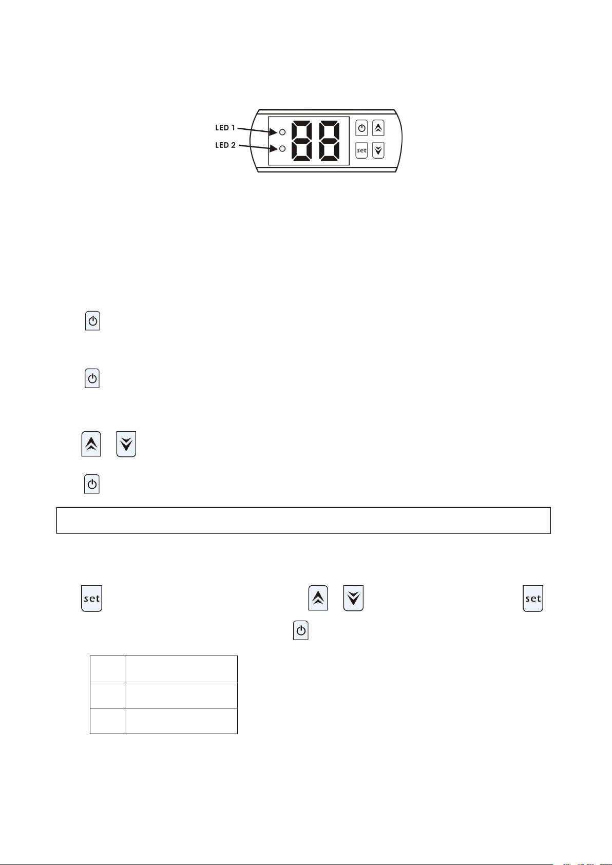
6.1 The buttons of LED wirecontroller
When the heat pump is running, the LED display shows the water inlet temperature.
6.2 Turn on/off the heat pump
6.3 Set the water temperature
6.4 Parameter checking
Code
Parameter
d0
Ambient temperature
d1
Water temperature
NOTE: the heat pump can run only if the water circle/filtration system is running.
LED 1 is on when compressor is running.
LED 2 is on if the unit is in fault.
Press to turn on the heat pump, the LED display shows the water setting temperature for 5s, then show
water inlettemperature.
Press again to turn off the heat pump.
Press or directly to adjust water temperature(range:.10—42℃)
Press to save the setting thenexit.
Press ,it will enter the parameter checking, Press or to choose the code d0/d1,press
again, it will show the measured value.Lastly press to exit.
Notice: It can’t set the Parameter data by end-users.
Page 30

27
7. Trouble shooting
7.1 Error code on the LED controller
Malfunction
Code
Reason
Solution
Too low or too high
ambient temperature
protection
P0
1. Ambient temperatureis
out of operating range:
12℃- 42℃.
2. Controllerfailure.
1. Wait the ambient temperature
to rise to 13℃ or to cool down
to 40℃ and restart.
2. Replace the new controller.
Water temperature sensor
failure
P1
Water temperature sensor
open circuit or short circuit.
Replace the new water
temperature sensor.
Ambient temperature
sensor failure
P2
Ambient temperature sensor
open circuit or short circuit.
Replace the new ambient
temperature sensor.
Low pressure protection
EL
1. Low pressure switch
disconnected or failure.
2. Gas leakage.
It must be repaired by the
professional technicians.
Page 31

28
7.2 Other Malfunctions and Solutions (No display on LED wire controller)
Malfunctions
Observing
Reason
Solution
Heat pump is
not running
LED wire controller
no display.
No power supply.
Check cable and circuit breaker if
it is connected.
LED wire controller
displays the actual
water temperature.
1. Water temperature is
reaching to setting value, HP
under constant temperature
status.
2. Heat pump just starts to run.
1. Verify water temperature
setting.
2. Startup heat pump after a few
minutes.
Short running
LED displays actual
water temperature, no
error code displays.
1. Fan NOT running.
2. Air ventilation is not enough.
3. Refrigerant is not enough.
1. Check the cable connections
between the motor and fan, if
necessary, it should be replaced.
2. Check the location of heat
pump unit and eliminate all
obstacles to make good air
ventilation.
3. Replace or repair the heat
pump unit. It must be
repaired by a professional
technician.
Water stains
Water stains on heat
pump unit.
1. Concreting.
2. Water leakage.
1. No action.
2. Check the titanium heat
exchanger carefully if it is any
defect.
Page 32
29
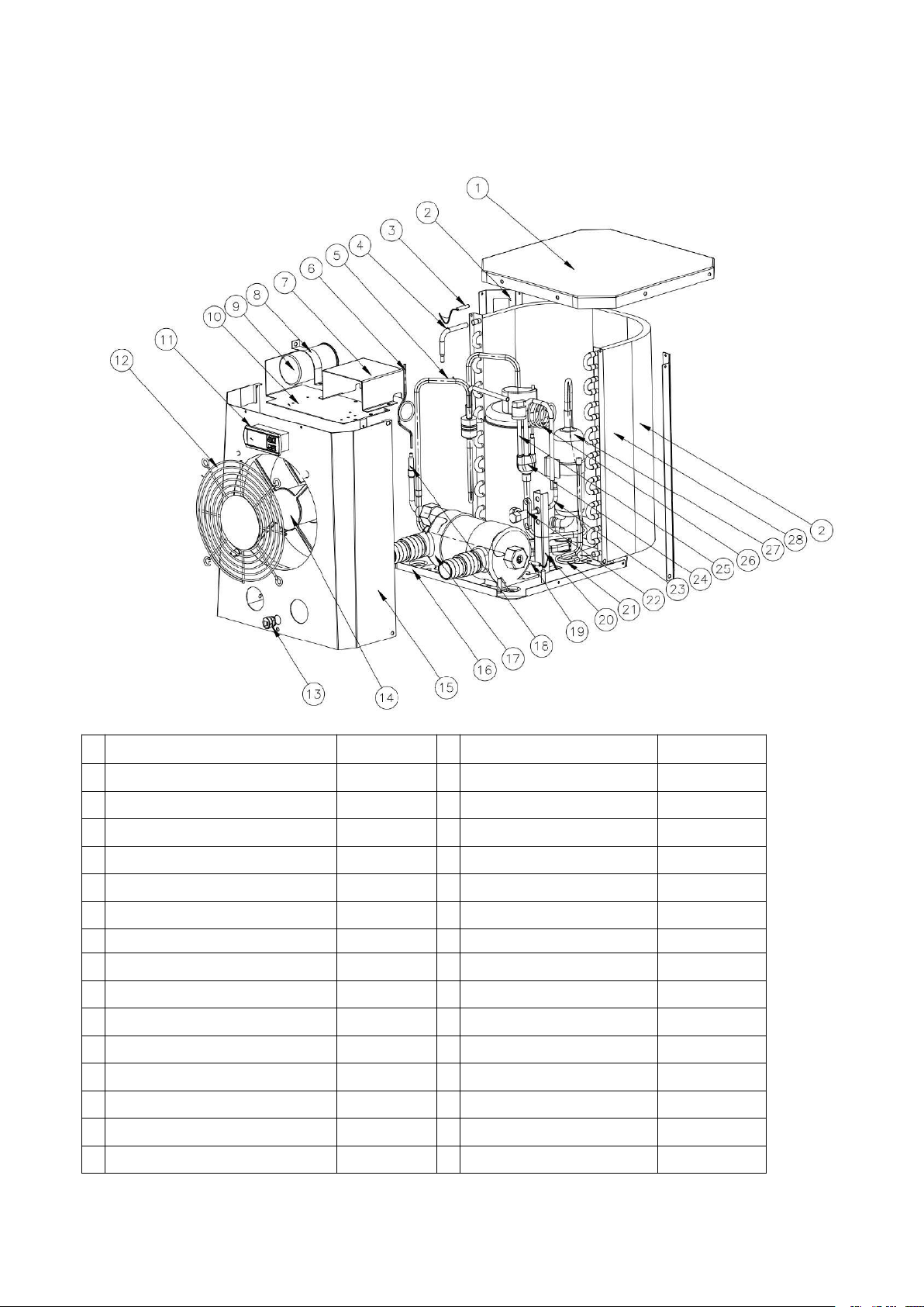
8. Exploded diagram
Unit: HPM20
No
Spare parts
HPM20
No
Spare parts
HPM20
1
Top cover
108680024
16
Base
108680029
2
Pillar
108680018
17
Titanium exchanger
102040699
3
Ambient temp. sensor
117110079
18
Copper pipe
113100026
4
Copper pipe
113100027
19
Water in temp. sensor
117110068
5
Exhaust pipe
113010232
20
Globe valve panel
108680007
6
Capillary
109000090
21
Gas collecting pipe
113050123
7
Electric box
108680016
22
Global valve
120000091
8
Compressor capacitance Clip
108010008
23
Copper pipe
113100008
9
Compressor capacitance
111000038
24
Gas return piping
113020328
10
Fan motor top plate
108680015
25
Low pressure switch
116000017
11
Controller
117020165
26
Globe valve capillary
109000048
12
Front grill
108680017
27
Compressor
101000191
13
Power cord buckle
142000126
28
Evaporator
103000236
14
Fan motor assembly
112000071
29
Electric cable
139000050
15
Front panel
108680030
Page 33
30
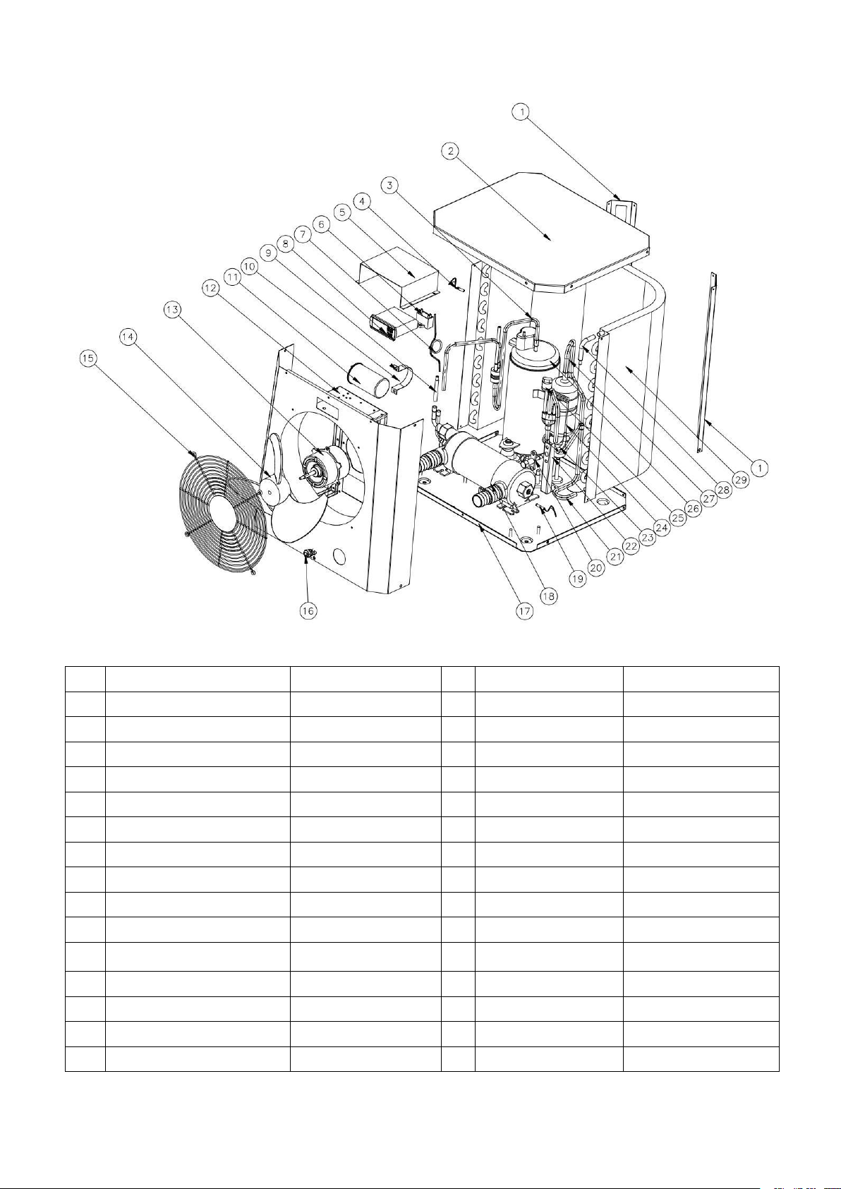
Unit: HPM30/HPM40
No.
Spare parts
HPM30/40
No.
Spare parts
HPM30/40
1
Pillar
108690009
16
Power cord buckle
142000126
2
Top cover
108690008
17
Base
108690020/108690022
3
Exhaust pipe
113010225/113010304
18
Titanium exchanger
102040700/102040746
4
Ambient temp. sensor
117110079
19
Water in temp. sensor
117110068
5
Electric box
108690015
20
Global valve
120000091
6
Fan capacitor
111000034
21
Gas collecting pipe
113050125
7
Capillary
109000038/109000012
22
Globe valve panel
108680007
8
Controller
117020165
23
Copper pipe
113100008
9
Copper pipe
113420129
24
Globe valve capillary
109000048/109000043
10
Compressor capacitance clip
108010006
25
Low pressure switch
116000017
11
Compressor capacitance
111300013/111000011
26
Compressor
101000183/101000210
12
Front panel assemble
108690021
27
Gas return piping
113020316/113020412
13
Fan motor
112000054/112000079
28
Copper pipe
113100027
14
Fan blade
132000024
29
Evaporator
103000237
15
Front grill
108690005
30
Electric cable
139000050
Page 34

31
9. Maintenance
(1) You should check the water supply system regularly to avoid the air entering the system and creation of
low water flow, because it would reduce the performance and reliability of HP unit.
(2) Clean your pools and filtration system regularly to avoid the damage of the unit.
(3) You should drain the water from heat pump if it will stop running for a long time (especially during the
(4) Check the water levels before the unit start after a long break in usage.
(5) When the unit is running, there will be condensate water discharging from the bottom of the unit. This is
winter season).
normal.
Page 35
32
INDEX
1. Especificaciones
2. Consejos de transporte
3. Dimensiones
4. Instalación y conexión
5. Cableado eléctrico
6. Funcionamiento del controlador
7. Solución de problemas
8. Diagrama explosionado
9. Mantenimiento
ATENCIÓN: Este manual contiene toda la información necesaria.
El instalador debe leer el manual y seguir atentamente las instrucciones de instalación y mantenimiento.
El instalador es responsable de la instalación del producto y debe seguir todas las instrucciones del
fabricante y las regulaciones en la aplicación. La instalación incorrecta respecto al manual implica la
exclusión de toda la garantía.
El fabricante declina cualquier responsabilidad por los daños causados a las personas, objetos y de los
errores debidos a la instalación que desobedezcan la guía del manual. Cualquier uso
que n
o esté definido
por el fabricante en el manual, será considerado como peligroso.
MINI HEATER
Manual de usuario y servicio
Gracias por usar la bomba de calor de piscina Mini Heater para su calefacción de piscina, calentará su agua de
la piscina y mantendrá la temperatura constante cuando la temperatura ambiente del aire sea superior 12℃.
Page 36
33
ADVERTENCIA
- Mantenga siempre la bomba de calor en un lugar ventilado y lejos de cualquier objeto que pueda provocar
un incendio.
- No suelde la tubería si hay refrigerante dentro de la máquina. Mantenga la máquina fuera del espacio
confinado cuando realice el llenado de gas.
- Por favor siempre vacíe el agua de la bomba de calor durante el invierno o cuando la temperatura ambiente
sea inferior a 0 ° C, o de lo contrario el intercambiador de Titanio se dañará por posible congelación. En tal
caso, su garantía se perderá.
- Siempre corte la fuente de alimentación si desea abrir la carcasa para tocar dentro de la bomba de calor,
porque hay electricidad de alto voltaje dentro.
- Por favor, mantenga la pantalla del controlador en un área seca, o bien cierre la cubierta aislante para
proteger la pantalla del controlador y que no se dañe por la humedad.
- La acción de llenado de gas debe ser realizada por un profesional con licencia de operación R32.
Page 37
34
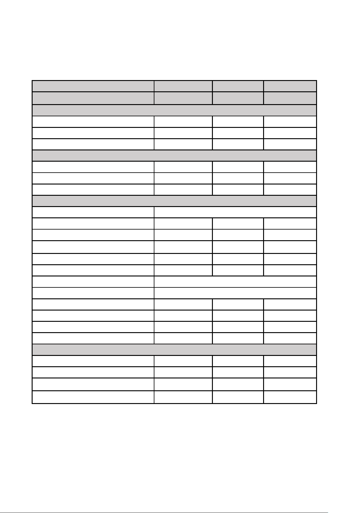
1. Especificaciones
1.1 Datos técnicos Bombas de calor
CE Standard, gas R32.
Modelos
HPM20
HPM30
HPM40
Code
71245
71258
71606
* Capacidad de ait 28ºC / agua 28ºC, Humedad 80%
Potencia Calor(kW)
2.5
4.2
5.5
Consumo de potencia(kW)
0.59
1
1.31
COP
4.2
4.2
4.2
* Capacidad de ait 15ºC / agua 26ºC, Humedad 70%
Potencia Calor(kW)
1.9
3.2
4.2
Consumo de potencia(kW)
0.56
0.91
1.2
COP
3.4
3.5
3.5
* General data
Voltaje(V)
220-240V~50Hz/1PH
Corriente nominal(A)
2.6
4.4
5.8
Corriente del fusible(A)
7.51316
Volumen de piscina recomendado (m3)
0-10
5-16
10-20
Flujo de agua recomendado (m3/h)
2
2
2.5-3.2
Presión del agua(Kpa)
151515
Condensador
Titanio en PVC
Conexión de agua (mm)
38/32
Velocidad del ventilador(rpm)
2500
1100
1100
Nivel de ruido (10m) dB(A)
484646
Nivel de ruido (1m) dB(A)
575555
Refrigerante R32 (g)
150
290
450
* Dimensión y peso
Peso neto (kg)
182626
Peso bruto (kg)
19
28.5
28.5
Dimensión neta (mm)
310*363.5*375
434*432.5*460
434*432.5*460
Dimensión de embalaje (mm)
365*440*440
485*510*530
485*510*530
* La información anterirmente nombrada esta sujeta a modificaciones sin previo aviso.
Page 38
35
2. Consejos de Transporte
2.1 Entrega del embalaje
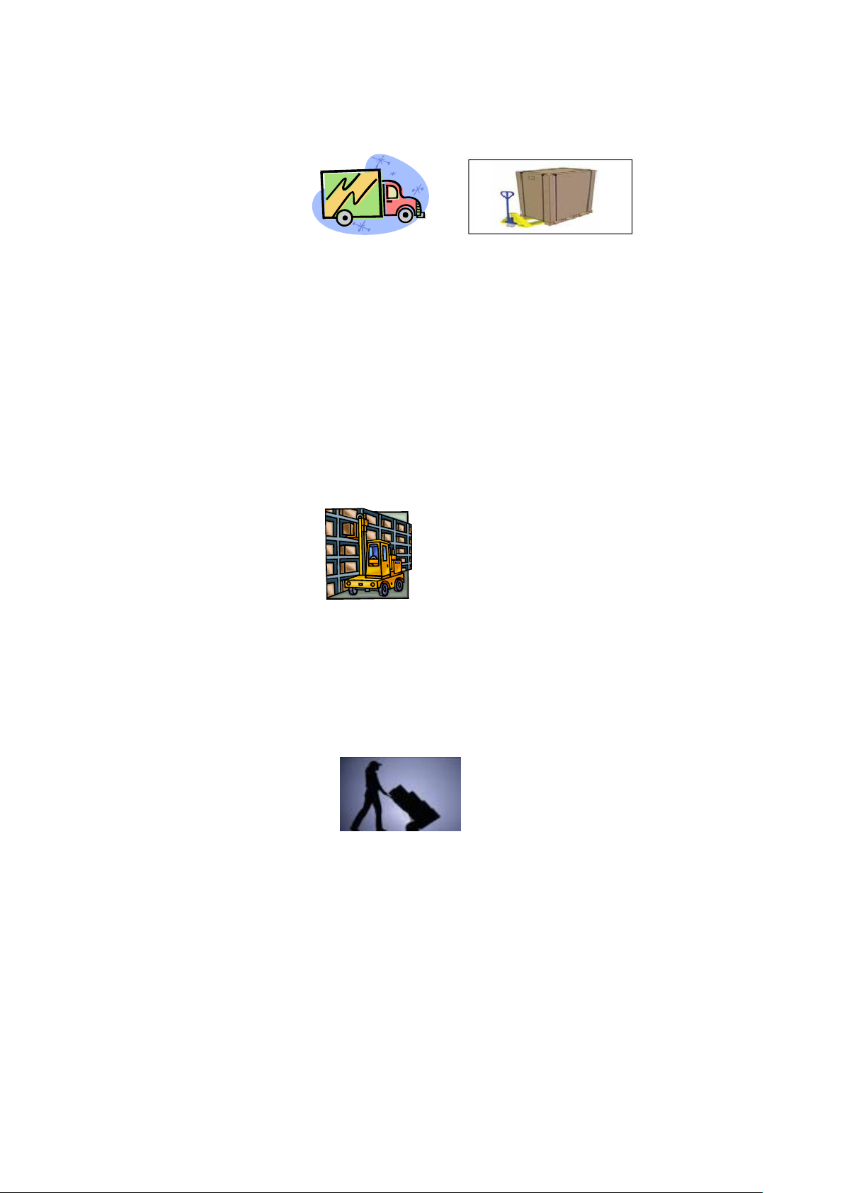
Para el transporte, las bombas de calor se fijan en un palet y se cubren con una caja de cartón.
Para evitar cualquier daño, la bomba de calor debe ser transferida con su embalaje..
Todo el material, incluso si el transporte es a cargo del proveedor, puede dañarse durante su envío al cliente y
es responsabilidad del destinatario asegurarse de la correcta entrega.
El destinatario, si observa daños en el embalaje, debe escribir todas las reseñas a la recepción en el albarán de
entrega del transportista. NO OLVIDE CONFIRMAR POR CARTA REGISTRADA AL TRANSPORTADOR EN 48
HORAS
2.2 Almacenaje.
* El almacén debe ser, espacioso, abierto, bien ventilado, con equipo de ventilación y sin fuente de fuego.
* La bomba de calor debe almacenarse y manipularse en posición vertical en su embalaje original. Si no es el
caso, es necesario un período mínimo de 24 horas antes de conectar la bomba a la alimentación eléctrica.
PROHIBIDO
2.3 Traslado a la posición final.
* Durante el desembalaje del producto y el transporte desde su palet hasta el lugar final de instalación, es
necesario mantener en posición vertical la bomba de calor.
* Está prohibido fumar y el uso de llamas cerca de la bomba de calor.
* La conexión de agua no garantiza la sujeción de la máquina, por el contrario, el peso de la bomba de calor
pueda dañar las conexiones de agua ocasionando averías en el producto. El fabricante no se responsabiliza de
los daños ocasionados por una incorrecta instalación.
Page 39
36
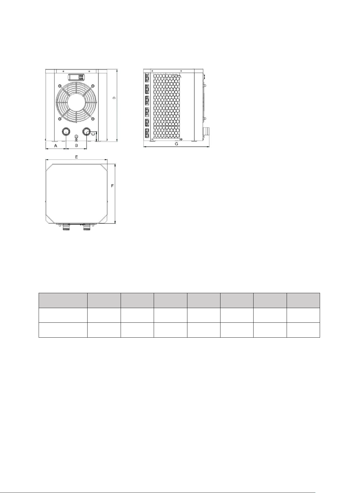
3. Dimensiones
Modelo / (mm)
ABCDEFG
HPM20
90.4
13050375
310
300
363.5
HPM30/HPM40
116.5
20050460
434
365
432.5
Page 40
37
4. Instalación y conexión
Atención:
1. Cualquier adición de productos químicos debe tener lugar en la tubería situada aguas abajo de la
2. Mantenga siempre la bomba de calor en posición vertical. Si la unidad se ha mantenido en ángulo,
Por favor, siga las instrucciones a la hora de instalar la bomba de calor:
bomba de calor.
espere al menos 24 horas antes de encender la bomba de calor.
4.1 Ubicación de la bomba de calor
La unidad funcionará correctamente en cualquier ubicación deseada, siempre que estén presentes los
siguientes tres elementos:
1. Aire fresco - 2. Electricidad - 3. Filtros de piscina
La unidad puede instalarse prácticamente en cualquier lugar exterior siempre que se mantengan las distancias
mínimas especificadas a otros objetos (véase el dibujo a continuación). Por favor, consulte a su instalador para
la instalación con una piscina cubierta. La instalación en un lugar ventoso no presenta ningún problema en
absoluto, a diferencia de la situación con un calentador de gas (incluyendo problemas de llama piloto).
ATENCIÓN: La unidad no debe instalarse en una zona de aire de ventilación limitada, ni colocarse en un
arbusto, que bloquearán la entrada de aire. Estas ubicaciones provocan que la unidad pueda recibir una
fuente continua de aire fresco. Al cambio de las estaciones, también puede colmatar la batería evaporadora
con las hojas de los arboles, lo que reducirá su eficiencia y afectaría a su vida útil.
4.2 Operación inicial
Nota: Para calentar el agua de la piscina (o de la tina caliente), la bomba del filtración debe estar
funcionando para que el agua circule a través de la bomba de calor. La bomba de calor no arrancará si el
agua no está circulando.
Page 41
38
4.3 Conexión de manguera
Nota: La fábrica sólo proporciona la unidad de la bomba de calor. Los otros elementos que se muestran en la
ilustración, son las partes necesarias para su instalación son suministradas por los usuarios o las personas que
realicen la instalación.
4.4 Conexión eléctrica
Antes de conectar la unidad, verifique que la tensión de alimentación coincida con la tensión de
funcionamiento de la bomba de calor.
El enchufe RCD se ha incluido con el cable de alimentación, el cual puede ofrecer protección eléctrica.
Page 42
39
Atención:
Asegúrese de que el enchufe de
alimentación sea seguro
Si el enchufe no es seguro, puede
provocar una descarga eléctrica,
sobrecalentamiento o incendio.
Nunca desenchufe el cable de
alimentación durante la operación
De lo contrario, podría producirse una
descarga eléctrica o un incendio
debido al
sobrecalentamiento.
Nunca utilice cables eléctricos
dañados o cables eléctricos no
especificados.
De lo contrario, podría provocar
una descarga eléctrica o un
incendio.
Una vez realizadas y comprobadas todas las conexiones, realice el siguiente procedimiento:
1. Encienda la bomba de filtración. Compruebe si hay fugas y compruebe que el agua fluye desde y hacia la
piscina.
2. Conecte la alimentación a la bomba de calor y presione el botón de encendido / apagado en el panel de
control electrónico. La unidad se pondrá en marcha después de la expiración del tiempo de espera (véase más
adelante).
3. Después de unos minutos, compruebe si el aire que sopla fuera de la unidad está más frío.
4. Apegue la bomba de calor antes que la bomba de filtración.
5. Deje que la bomba de calor y la bomba del filtro funcionen 24 horas al día hasta que se alcance la
temperatura deseada del agua. La bomba de calor dejará de funcionar en este punto. Después de esto, se
reiniciará automáticamente (siempre y cuando la bomba del filtro esté funcionando) siempre que la
temperatura del agua de la piscina disminuya 2 grados respecto a la temperatura deseada.
Dependiendo de la temperatura inicial del agua en la piscina y la temperatura del aire, puede tardar varios
días para calentar el agua a la temperatura deseada. Una buena cubierta de la piscina puede reducir
drásticamente el tiempo requerido para ello.
Tiempo de retardo - La unidad de la bomba de calor debe estar equipada con una protección de reiniciación
temporizada de 3 minutos transitoria. El control del temporizador es una parte integral del circuito de control.
El funcionamiento del temporizador permitirá reiniciar automáticamente la unidad de la bomba de calor
aproximadamente 3 minutos después de cada interrupción del circuito de control. Incluso una simple
interrupción de alimentación eléctrica activará el temporizador de 3 minutos de manera transitoria y
prevendrá la unidad se reinicie hasta que se cumplan los 3 minutos.
Page 43

40
4.5 Condensación
El aire aspirado en la bomba de calor se enfría fuertemente por el funcionamiento de la bomba de calor para
calentar el agua de la piscina, lo que puede causar condensación en las aletas del evaporador. La cantidad de
condensación puede ser de hasta varios litros por hora a alta humedad relativa. Esto a veces se considera
erróneamente como una fuga de agua.
Page 44
41
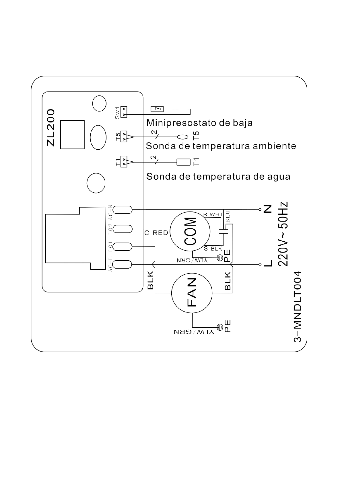
5. Cableado eléctrico
5.1 ESQUEMA ELECTRICO DE LA BOMBA DE CALOR
HPM20
Page 45
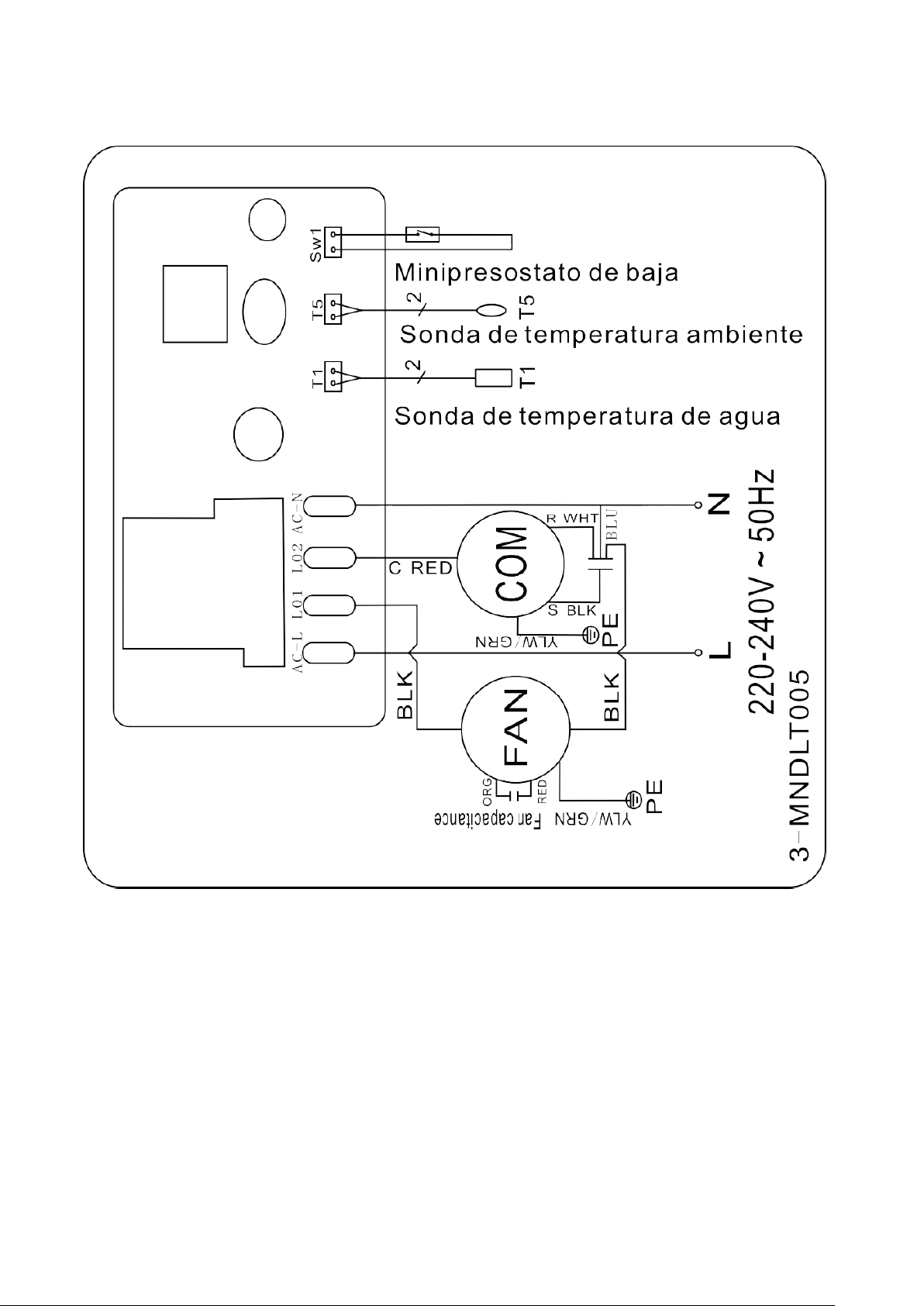
42
5.2 ESQUEMA ELECTRICO DE LA BOMBA DE CALOR
HPM30/HPM40
NOTA:
(1) Por encima del diagrama de cableado eléctrico sólo para su referencia, se somete al diagrama de cableado
que aparece en la máquina.
(2) La bomba de calor debe estar bien conectada a tierra, aunque el intercambiador de calor de la unidad está
aislado eléctricamente del resto de la unidad. La conexión a tierra de la bomba de calor, aún es necesaria para
protegerla contra cortocircuitos dentro de la misma.
Desconexión: Los medios de desconexión (interruptor automático, fusible o relés) deben estar ubicados a la
vista y fácilmente accesibles desde la unidad. Esto es una práctica común en bombas de calor comerciales y
residenciales. Desconecte el sistema de alimentación remota cuando tenga que realizer manteniento dentro
de la máquina.
Page 46
43
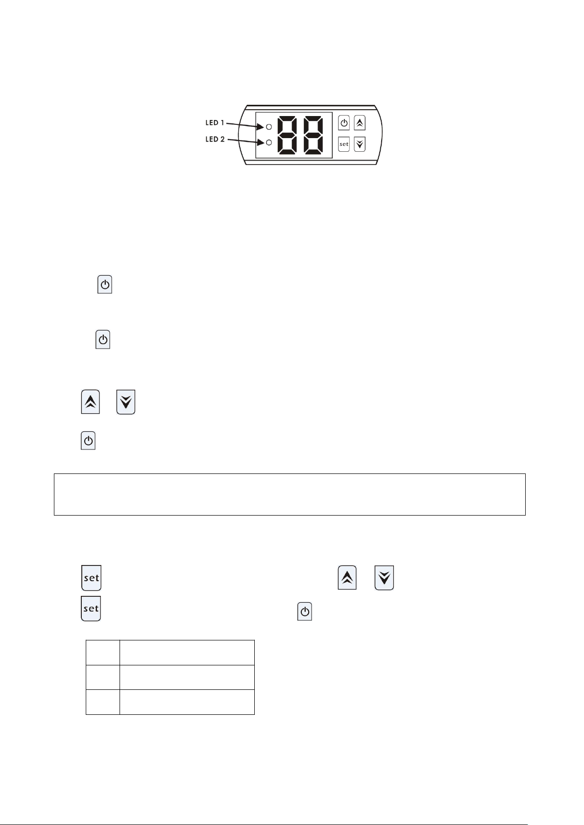
6. Funcionamiento del controlador de pantalla
6.1 Los botones del controlador LED
Nota: la bomba de calor puede funcionar sólo si el sistema de circuito de agua / filtración está
funcionando.
Code
Parámetro
d0
Temperatura ambiente
d1
Temperatura de agua
Cuando la bomba de calor está funcionando, la pantalla LED muestra la temperatura del agua de entrada.
El LED 1 está encendido cuando el compresor está funcionando.
El LED 2 está encendido si hay problemas.
6.2 Arranque o detenga la bomba de calor
Presione para iniciar la bomba de calor, la pantalla LED mostrará la temperatura del agua deseada
durante 5 segundos y luego mostrará la temperatura del agua de entrada..
Presione para detener la bomba de calor.
6.3 Ajuste de la temperatura del agua
Pulse y para ajustar la temperatura del agua deseada (10—42℃)
Pulse nuevamente para almacenar los nuevos datos.
6.4 Cómo comprobar los parámetros
Pulse ,Entrará en la comprobación de parámetros, Pulse y para elegir el código d0 / d1,
Pulse , mostrará el valor medido. Por último pulse para salir.
Aviso: no puede establecer los datos del parámetro por los usuarios finales.
Page 47

44
7. Mal funcionamiento y solución de problemas
7.1 Código de error mostrado en el controlador de cable de LED
Avería
Código
de error
Motivo
Solución
Protección por
temperatura ambiente
demasiado baja o
demasiado alta
P0
1. La temperatura ambiente
está fuera del rango de
operación: 12 ℃ - 42 ℃.
2. Fallo del controlador.
1. 1. Espere a que la temperatura
ambiente aumente a 13 ℃ o se enfríe
a 40 ℃ para volver a arrancar.
2. Reemplace el nuevo controlador.
Fallo del sensor de
temperatura del agua
P1
Sensor de temperatura del
agua circuito abierto o
cortocircuito.
Reemplace el nuevo sensor de
temperatura del agua.
Fallo del sensor de
temperatura ambiente
P2
Sensor de temperatura
ambiente circuito abierto o
cortocircuito.
Reemplace el nuevo sensor de
temperatura ambiente.
Protección de baja presión
EL
1. Interruptor de baja presión
desconectado o averiado.
2. Fuga de gas.
Debe ser reparado por los técnicos
profesionales.
Page 48

45
7.2 Otros fallos y soluciones (No se muestra en el controlador con cable LED)
Avería
Descripción
Motivos
Solución
La bomba de
calor no se
está
operando.
Ninguna visualización
sobre el controlador
LED se aprecia.
No hay alimentación de potencia.
Chequee el cable y el cambiador
del circuito, verifique si están
conectados.
El controlador de cable
de LED muestra la
temperatura del agua
actual.
La temperature del agua está
llegando al valor ajustado, la
bomba de calor se encuentra en
estado de temperatura
constante.
2. La bomba de calor comienza
justo a funcionar.
1. Verifica el ajuste de la
temperatura del agua.
2. Inicie la bomba de calor después
de algunos minutos.
Operación
corta
LED muestra la
temperature actual del
agua, no se muestra el
código de error.
1. Ventilador NO funciona.
2. La ventilación del aire no es
suficiente.
3. El refrigerante no es suficiente.
1. Chequee las conexiones de cable
entre el motor y el ventilador, si es
necesario, deben ser remplazados.
2. Compruebe la ubicación de la
unidad de la bomba de calor, y
elimine todos los obstáculos para
tener una buena ventilación del aire.
3. Reemplace o repare la unidad de
la bomba del calor.
Manchas de
agua
Manchas de agua en la
unidad de la bomba de
calor
1. Protección
2. Fuga del agua.
1. Ninguna accion.
2. Verifique con cuidado el
intercambiador de calor de titanio si
hay algún fallo de fuga.
Page 49
46
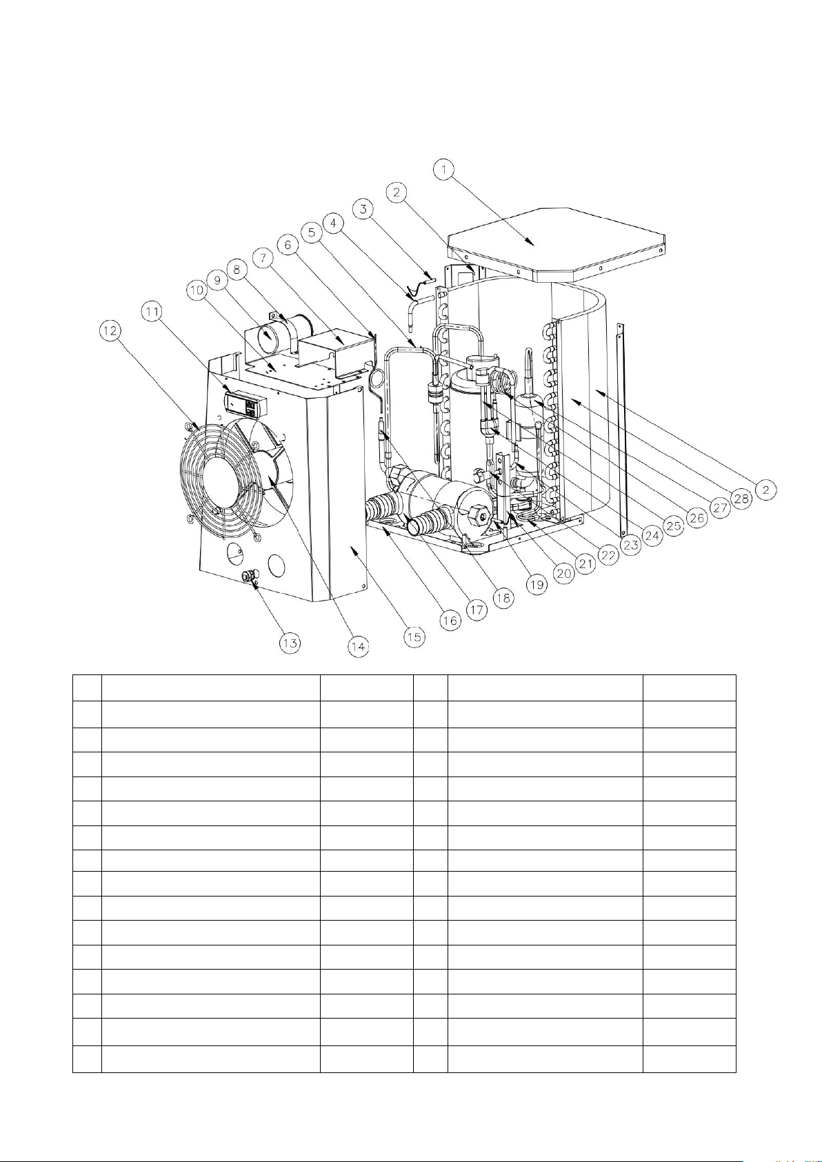
8. Diagrama Explosionado
Unit: HPM20
No.
Spare parts
HPM20
No.
Spare parts
HPM20
1
La cubierta superior
108680024
16
Base
108680029
2
Pilar
108680018
17
Intercambiador de titanio
102040699
3
Temperatura ambiente. sensor
117110079
18
Tubo de cobre
113100026
4
Tubo de cobre
113100027
19
Agua en temp. sensor
117110068
5
Tubo de escape
113010232
20
Panel de válvula de globo
108680007
6
Capilar
109000090
21
Gas collecting pipe
113050123
7
Caja electrica
108680016
22
Válvula de globo
120000091
8
Clip de capacitancia del compresor
108010008
23
Tubo de cobre
113100008
9
Capacitancia del compresor
111000038
24
Tubería de retorno de gas
113020328
10
Placa superior del motor del
108680015
25
Interruptor de baja presion
116000017
11
Controlador
117020165
26
Válvula de globo capilar
109000048
12
Parrilla delantera
108680017
27
Compresor
101000191
13
Hebilla del cable de alimentación
142000126
28
Evaporador
103000236
14
Montaje del motor del ventilador
112000071
29
Cable eléctrico
139000050
15
Panel frontal
108680030
Page 50
47
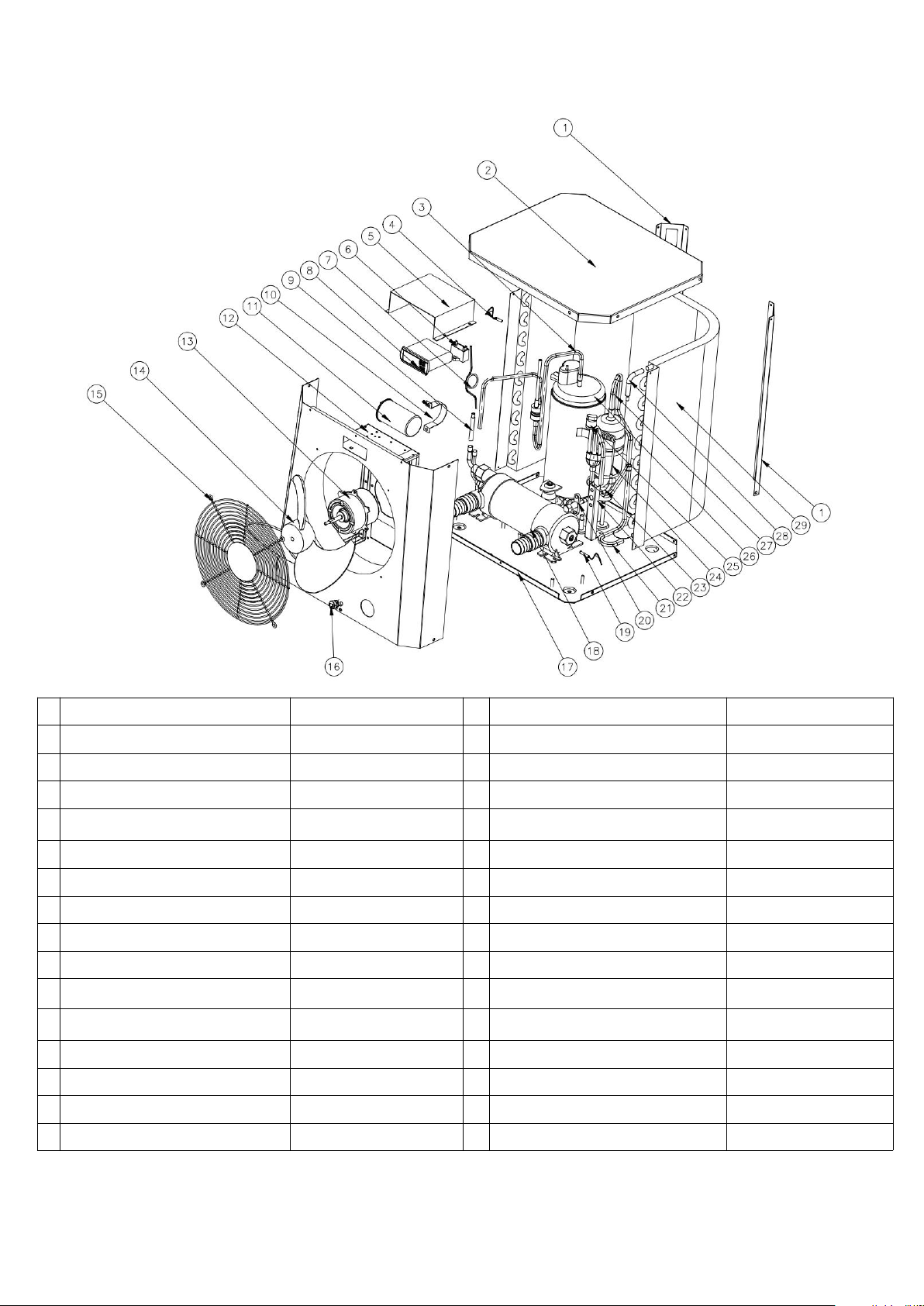
Unit: HPM30/HPM40
N
Spare parts
HPM30/40
No
Spare parts
HPM30/40
1
Pilar
108690009
16
Hebilla del cable de alimentación
142000126
2
La cubierta superior
108690008
17
Base
108690020/108690022
3
Tubo de escape
113010225/113010304
18
Intercambiador de titanio
102040700/102040746
4
Temperatura ambiente. sensor
117110079
19
Agua en temp. sensor
117110068
5
Caja electrica
108690015
20
Válvula de globo
120000091
6
Condensador del
111000034
21
Tubo colector de gas
113050125
7
Capilar
109000038/109000012
22
Panel de válvula de globo
108680007
8
Controlador
117020165
23
Tubo de cobre
113100008
9
Tubo de cobre
113420129
24
Válvula de globo capilar
109000048/109000043
10
Clip de capacitancia del
108010006
25
Interruptor de baja presion
116000017
11
Capacitancia del compresor
111300013/111000011
26
Compresor
101000183/101000210
12
Montaje del panel frontal
108690021
27
Tubería de retorno de gas
113020316/113020412
13
Motor del ventilador
112000054/112000079
28
Tubo de cobre
113100027
14
Aspa del ventilador
132000024
29
Evaporador
103000237
15
Parrilla delantera
108690005
30
Cable eléctrico
139000050
Page 51

48
9. Mantenimiento
(1) Debe revisar regularmente el sistema de filtración, bajo flujo de agua y obstrucciones en la batería
(2) Debe limpiar regularmente sus piscinas y el sistema de filtración para evitar el daño a la unidad por la
(3) .Deberá evacuar el agua del condensador de la bomba de calor, cuando esta deje de funcionar durante un
(4) En otras palabras, debe chequear las unidades por completo y llenar el sistema con agua completamente
(5) Cuando la unidad está funcionando, hay continuamente un poco de descarga de agua debajo de la unidad.
evaporadora, ya que esto puede producir averías, reduciendo el rendimiento y la fiabilidad de la bomba de
calor.
suciedad, obstruyendo el filtro.
largo periodo de tiempo.
antes de que la unidad comience a funcionar de nuevo.
Page 52
49
INDEX
1. Spécifications
2. Conditions de transport
3. Dimension
4. Installation et connexion
5. Câblage électrique
6. Fonctionnement du contrôleur
7. Guide de dépannage
8. Schéma éclaté
9. Entretien
ATTENTION : Ce manuel contient toutes les informations nécessaires à l’utilisation et à l’installation de
votre pompe à chaleur.
L’installateur doit lire le manuel et suivre attentivement les instructions d’utilisation, de mise en œuvre et de
sécurité du produit.
L’installateur est responsable de l’installation de l’appareil et du respect des instructions du fabricant et de la
règlementation en vigueur. Le non-respect de ce manuel implique l’exclusion de toute garantie.
Le fabricant décline toute responsabilité des dommages occasionnés aux personnes, objets et des erreurs
dues à l’installation dans de mauvaises conditions.
Toute utilisation à des fins non conformes à celles qui sont à l’origine de sa fabrication sera considérée comme
dangereuse.
MINI HEATER
Notice d’installation et d’utilisation
Nous vous remercions d’avoir choisi la pompe à chaleur de piscine Mini heater pour chauffer l’eau de votre
piscine, elle va chauffer l'eau de votre piscine et la maintenir à une température constante lorsque la
température ambiante se situe au-dessus de 12°C.
Page 53

50
ATTENTION
- Veuillez toujours installer la pompe à chaleur dans un lieu bien aéré et à l'écart de tout objet qui pourrait
provoquer un incendie.
- Ne soudez pas le circuit gaz s’il y a du réfrigérant dans la machine. Lors du remplissage en gaz veillez à
maintenir la machine en dehors de l'espace confiné.
- Veillez, s'il vous plaît, à procéder à la vidange de l'eau de la pompe à chaleur afin d'éviter des possibles
dommages provoqués par la formation de gel durant l'hiver ou bien lorsque la température ambiante est
inférieure à 0ºC. En effet, l'échangeur de Titane pourrait être endommagé para la formation de gel, et dans
ce cas, la garantie serait perdue.
- Veuillez prendre soin de toujours couper l’alimentation électrique avant d’ouvrir et d’intervenir sur la
machine, pour éviter tout risque d'électrocution, de par la présence de haut voltage.
- Veuillez maintenir, s'il vous plaît, le contrôleur de l'écran dans une zone sèche, ou bien le protéger par un
boitier de protection étanche, afin d' éviter de possibles dommages provoqués par l'humidité.
- Le circuit gaz doit être mis au vide avant de le remplissage en gaz R32 à partir de la vanne d’arrêt de la
machine.
- L'action de remplissage de gaz doit être effectuée par un professionnel habilité muni d'une licence
d'exploitation R32.
Page 54
51
1. Spécifications
1.1 Pompe à chaleur de Piscine
Unité
HPM20
HPM30
HPM40
Code
71245
71258
71606
* Puissance de chauffage Air28/Eau28/Humidité 80%
Puissance de chauffage (kW)
2.5
4.2
5.5
Consommation (kW)
0.59
1
1.31
COP
4.2
4.2
4.2
* Puissance de chauffage Air15/Eau26/Humidité 70%
Puissance de chauffage (kW)
1.9
3.2
4.2
Consommation (kW)
0.56
0.91
1.2
COP
3.4
3.5
3.5
* Données générales
Alimentation électrique (V)
220-240V~50Hz/1PH
Courant Nominal (A)
2.6
4.4
5.8
Disjoncteur préconisé
7.51316
Volume de la piscine conseillé (m3)
0-10
5-16
10-20
Débit d’eau préconisé (m3/h)
2
2
2.5-3.2
Pression de l'eau (Kpa)
151515
Condenseur
Titane en PVC
Diamètre entrée-sortie (mm)
38/32
Vitesse de ventilateur (rpm)
2500
1100
1100
Niveau de bruit à 10m dB(A)
484646
Niveau de bruit à 1m dB(A)
575555
Gaz refrigerant R32 (g)
150
290
450
* Dimension & Poids
Poids net (kg)
182626
Poids brut (kg)
19
28.5
28.5
Dimension (mm)
310*363.5*375
434*432.5*460
434*432.5*460
Dimension d’emballage (mm)
365*440*440
485*510*530
485*510*530
* Les données ci-dessus sont sujettes à modification sans préavis.
CE Standard, gas R32.
Page 55
52
2. Conditions de transport
2.1 Consignes de livraison du colis
Pour le transport, la pompe à chaleur est fixée en usine sur une palette et protégée par un cartonnage. Afin
d’éviter les dommages, la pompe à chaleur doit être transportée emballée sur sa palette.
Même si le transport est à la charge du fournisseur, tout matériel peut être endommagé lors de son
acheminement chez le client et il est de la responsabilité du destinataire de s’assurer de la conformité de la
livraison. Le destinataire doit émettre des réserves écrites à la réception sur le bordereau de livraison du
transporteur s’il constate des dégradations de l’emballage. NE PAS OUBLIER DE CONFIRMER PAR LETTRE
RECOMMANDEE AU TRANSPORTEUR SOUS 48 HEURES.
2.2 Consignes de stockage
Une pompe à chaleur doit être stockée et déplacée en position verticale dans son emballage d’origine. Si ce
n’est pas le cas, elle ne peut être mise en œuvre immédiatement. Un délai minimum de 24 heures sera
nécessaire avant de mettre le produit sous tension.
INTERDICTION
2.3 Consignes lors du transfert de la pompe à chaleur vers son emplacement final
Lors du déballage du produit et du transfert de sa palette d’origine vers son emplacement final, il faut maintenir la
pompe à chaleur en position verticale. Les raccords hydrauliques ne sont pas là pour assurer la fonction de poignée
de levage, bien au contraire : solliciter de tout le poids de la pompe les sorties et entrée des raccordements
hydrauliques peut endommager définitivement le produit. Le fabricant ne pourrait alors être tenu responsable
en cas de casse.
Page 56
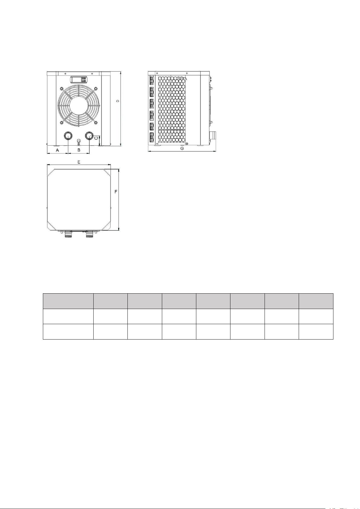
53
3. Dimension
Item / (mm)
ABCDEFG
HPM20
90.4
13050375
310
300
363.5
HPM30/HPM40
116.5
20050460
434
365
432.5
Page 57
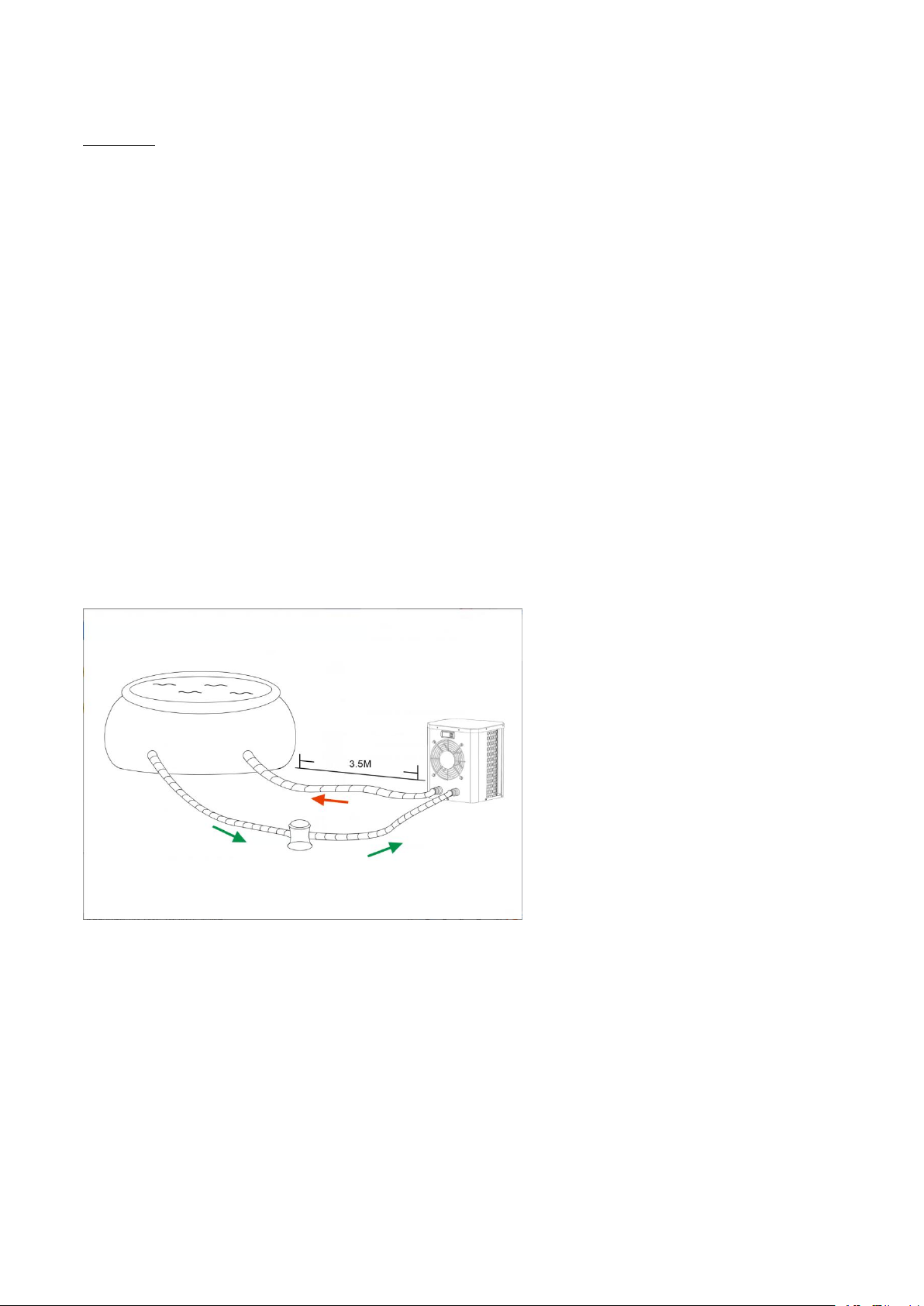
54
4. Installation et connexion
Attention:
Avant l’installation, merci de prendre connaissance des indications ci-dessous :
1. Tous les produits contenant des liquides chimiques, doivent être installés en aval de la pompe à
chaleur piscine.
2. Toujours laissez la pompe à chaleur piscine verticale. Si la machine a été penché durant son transport,
attendez au moins 24 heures avant de démarrer la pompe à chaleur.
L'appareil peut être installé presque n'importe où à l'extérieur, à condition que les trois facteurs soient
satisfaits :
1. Une bonne ventilation - 2. Une alimentation électrique stable et fiable - 3. Un système d'eau recyclée
ATTENTION : L'unité ne doit pas être installée dans une zone où la ventilation d'air est limitée ou les
emplacements qui ne peuvent pas fournir de façon continue de l'air, s’assurer que l’entrée d’air ne puisse
jamais être obstruée. Les feuilles et autres débris peuvent se coller sur l'évaporateur, ce qui réduit son
efficacité et affectera sa durée de vie.
4.1 Positionnement de la pompe à chaleur piscine
L’unité peut être installé à n'importe quel endroit à l'extérieur à condition que les distances minimales
montrées dans le schéma (ci-dessous) soient conformes. Pour l’installation à l’intérieur, demandez conseil à
votre installateur. L’installation dans un endroit venteux ne pose aucun problème, sauf si un chauffage au gaz se
trouve à proximité (risques dus aux flammes).
Page 58

55
4.2 Mise en service initiale de l'unité
Nota : Veuillez-vous assurer que la pompe de filtration fonctionne avec un débit d'eau adéquat. La pompe à
4.3 Raccordement des tuyaux
Seule la pompe à chaleur est fournie. Tous les autres éléments, y compris les tuyaux, doivent être fournis par
l'utilisateur ou l'installateur.
4.4 Raccordement électrique
Avant de brancher l'appareil, vérifiez que la tension d'alimentation correspond à la tension de fonctionnement
de la pompe à chaleur.
La prise RCD est fournie avec un câble d'alimentation offrant une protection électrique.
chaleur de démarre pas si l’eau ne circule pas à l’intérieur.
Note :
Page 59
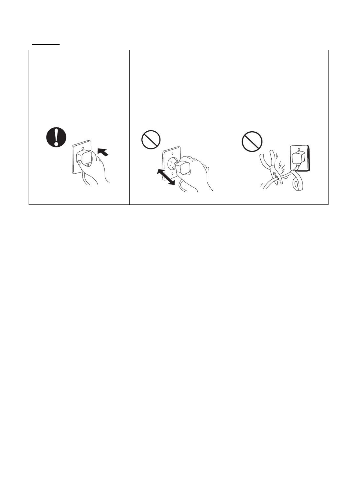
56
Attention:
Assurez-vous que la prise
électrique est conforme
Si la prise n’est pas bien branchée,
vous risquez une décharge
électrique, un échauffement et un
risque d’incendie.
Ne jamais débrancher la prise
électrique pendant le
fonctionnement de la pompe à
chaleur
Sinon, vous risquez une décharge
électrique un incendie suite à la
surchauffe.
Ne jamais utiliser des câbles
électriques endommagés ou non
conforme à leur utilisation
Sinon, cela pourrait provoquer une
décharge électrique, un
échauffement et un risque
d’incendie.
Une fois que toutes les connexions ont été faites, merci de suivre ces étapes:
(1) Allumez votre pompe de filtration, vérifiez l’absence de fuites d'eau et le débit au niveau de la piscine
(2) Activez l'alimentation électrique de l'appareil, puis appuyez sur la touche ON / OFF du contrôleur.
(3) Après un fonctionnement de quelques minutes, assurez-vous que l’air ventilé est froid.
(4) Lorsque vous désactivez la pompe de filtration, l'unité doit également être désactivée automatiquement, sinon,
veuillez contrôler le commutateur de débit.
En fonction de la température initiale de l'eau dans la piscine et la température de l'air, il est nécessaire de faire
fonctionner l’installation pendant plusieurs jours pour chauffer l'eau à la température souhaitée.
Une bonne protection de la piscine (couverture, bâche solaire) peut réduire considérablement la durée requise.
Commutateur de débit d'eau :
L’unité est équipée d'un détecteur de débit d’eau pour s’assurer que la pompe à chaleur fonctionne avec un débit
d'eau suffisant. Il est activé lorsque la pompe de filtration de la piscine fonctionne et il s'éteint lorsque la pompe
s'arrête.
Temporisation :
L’unité est équipée d'une protection intégrée de redémarrage temporisée de 3 minutes. La temporisation est une
partie intégrante du circuit de commande et de protection du compresseur.
Page 60

57
La fonction de temporisation interdit tout redémarrage automatiquement de l'appareil (pendant environ 3 minutes)
4.5 Condensation
après chaque interruption sur la commande. Même une brève interruption de courant active la temporisation de 3
minutes et empêche le redémarrage de l'appareil jusqu'à ce que le compte à rebours de 3 minutes soit terminé.
L'air aspiré dans la pompe à chaleur est fortement refroidi par le fonctionnement de la pompe à chaleur pour
chauffer l'eau de la piscine, ce qui peut provoquer la condensation sur les ailettes de l'évaporateur. Le niveau
de la condensation peut être de plusieurs litres par heure à une humidité relative élevée. Ceci est parfois
considérées à tort comme une fuite d'eau.
Page 61
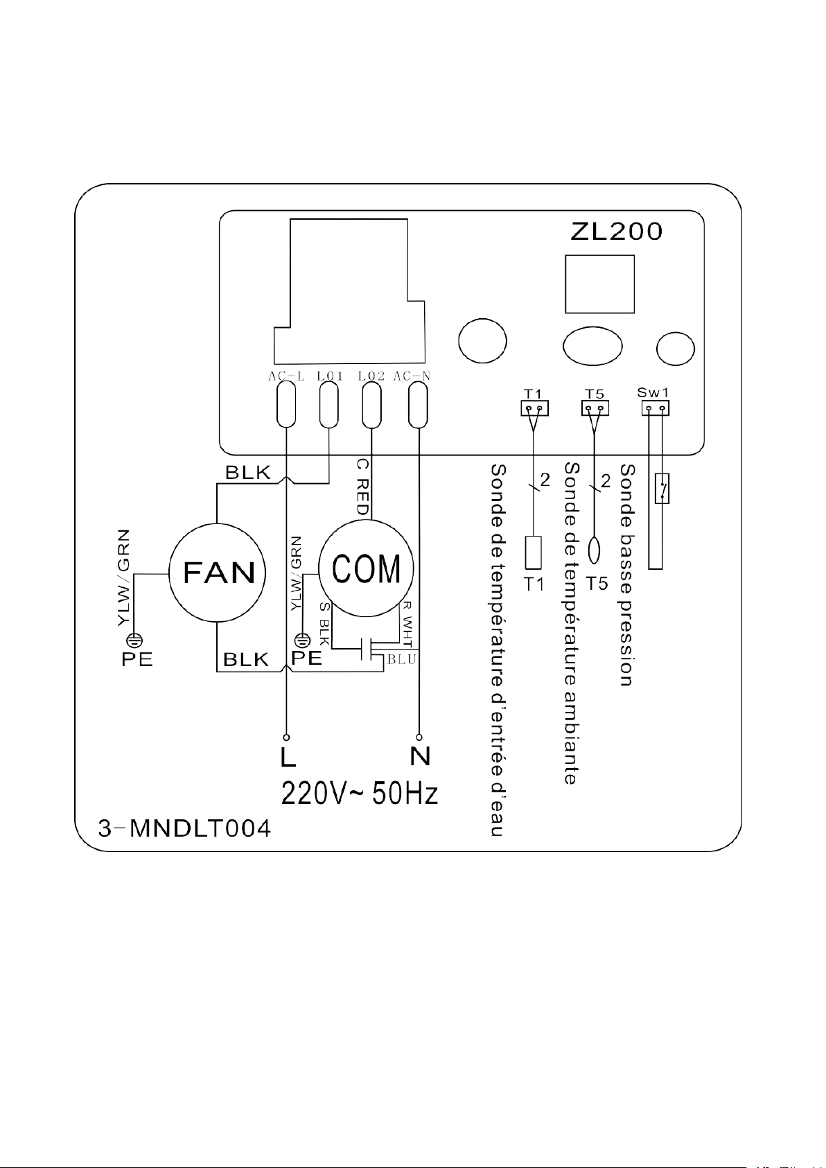
58
5. Câblage électrique
5.1 Schéma de câblage de la pompe à chaleur de piscine
HPM20
Page 62
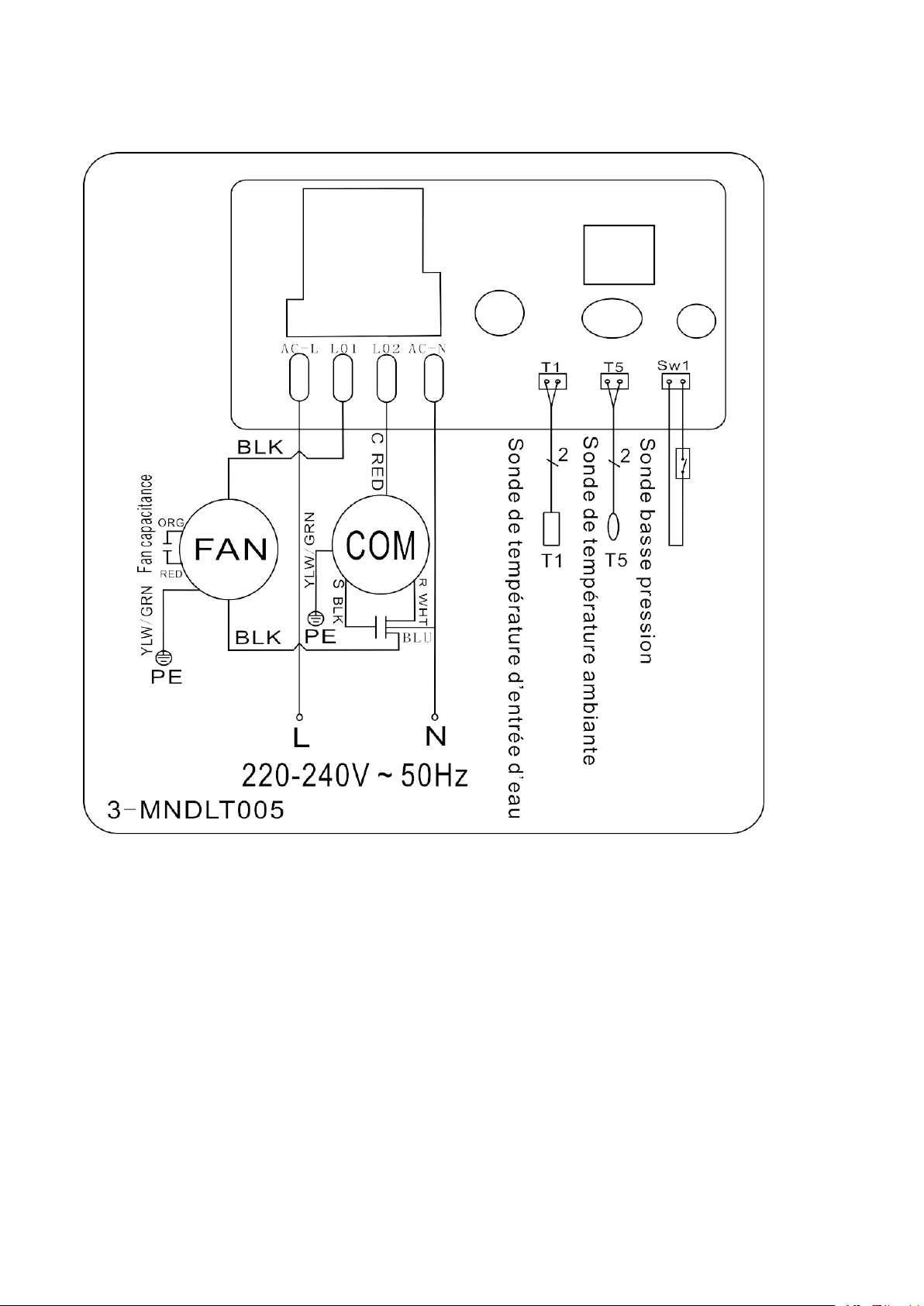
59
5.2 Schéma de câblage de la pompe à chaleur de piscine
HPM30/HPM40
NOTE :
(1) Le schéma de câblage électrique ci-dessus est seulement valable pour votre référence, veuillez utiliser le schéma
de câblage affiché sur la machine.
(2) La pompe à chaleur de piscine doit être bien raccordée à la terre, bien que l'échangeur de chaleur soit
électriquement isolé du reste de l'unité. La mise à la terre de l'unité est toujours nécessaire pour vous protéger
contre les courts-circuits éventuels de l'unité.
Sectionneur : Un moyen d’interruption électrique (disjoncteur, interrupteur à fusibles) doit être en vue et
facilement accessible de l'unité. C’est une pratique courante et de sécurité pour les pompes à chaleur résidentielles
et commerciales. Il permet la mise hors tension à distance de l'équipement sans surveillance et d’’isoler
l'alimentation à l'unité alors que l'appareil est en réparation.
Page 63
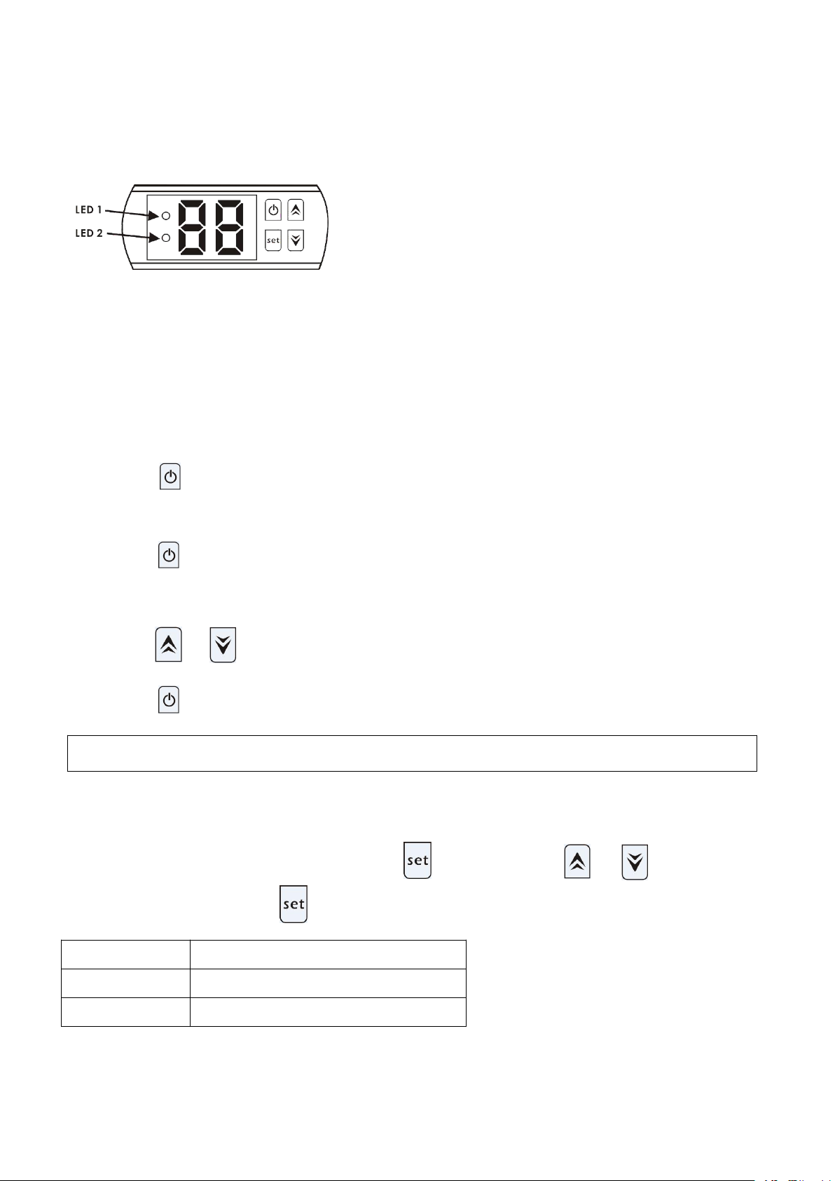
60
6. Fonctionnement du contrôleur
NOTE : Attention la pompe à chaleur ne fonctionne que si le système de filtration est en route.
Paramètre
Paramètre
d0
La température ambiante
d1
Température de l'eau
6.1 Les fonctions du tableau de commande LED
Lorsque la pompe à chaleur est en cours de fonctionnement, l’écran LED affichera la température d'arrivée d'eau.
Lorsque la pompe à chaleur fonctionne, la LED 1 s’éclaire.
Lorsque la pompe à chaleur est en défaut, la LED 2 s’éclaire.
6.2 Démarrer ou arrêter la pompe à chaleur
Appuyez sur pour démarrer la pompe à chaleur, l’écran affiche la température souhaitée pendant 5 secondes
et ensuite la température d’entrée d’eau.
Appuyez sur pour arrêter la pompe à chaleur.
6.3 Réglage de la température d’eau :
Appuyez sur et pour sélectionner la température souhaitée (valeur : 10 - 42°C).
Appuyez sur pour sauvegarder la valeur sélectionnée.
6.4 Comment vérifier les paramètres.
En mode de veille ou de fonctionnement, appuyez sur , ensuite appuyez sur ou afin de choisir le
paramètre d0 ou d1, appuyez sur , pour le sélectionner et afficher la valeur.
Note : Les valeurs ne peuvent être modifiées par les utilisateurs.
Page 64

61
7. Guide de dépannage
7.1 Code d'erreur affichée sur le tableau de commande
Dysfonctionnement
Code
d’erreur
Raison
Solution
Protection trop basse ou
trop élevée de la
température ambiante
P0
1. La température ambiante
est en dehors de la plage de
fonctionnement : 12°C – 42°C.
2. Panne du contrôleur.
1. Attendez que la température
ambiante monte à 13°C ou baisse
à 42°C pour redémarrer.
2. Remplacer le contrôleur.
Défaillance du capteur de
température de l'eau
P1
Capteur de température d'eau
circuit ouvert ou court-circuit.
Remplacez le capteur de
température d'eau.
Capteur de température
ambiante
P2
Capteur de température
ambiante en circuit ouvert ou
en court-circuit.
Remplacez le capteur de
température ambiante.
Protection basse pression
EL
1. Interrupteur basse
pression déconnecté ou en
panne
2. Fuite de gaz.
Mandater un technicien habilité
pour intervenir sur le circuit gaz.
Page 65

62
7.2 Autres dysfonctionnements et Solutions (Pas affiché sur le contrôleur LED)
Dysfonctionnements
Observations
Raisons
Solution
Pompe à chaleur ne
fonctionne pas
Aucun affichage sur
le contrôleur à LED
Pas d'alimentation.
Vérifiez le disjoncteur et le
raccordement électrique
Contrôleur à LED
affiche la
température réelle
de l'eau.
1. Température de l'eau
atteint la valeur fixée, la
pompe à chaleur est à l’arrêt
en état de veille.
2. Pompe à chaleur
commence juste à
fonctionner (3 minutes)
1. Vérifiez le réglage de température
de l'eau.
2. Attendre la démarrage de la
pompe à chaleur, quelques minutes.
Fonctionnement
court
Contrôleur à LED
affiche la
température réelle
de l'eau, aucun
code d’erreur ne
s’affiche
1. Ventilateur ne fonctionne
pas
2. La ventilation d'air n'est
pas suffisante
3. Réfrigérant ne suffit pas.
1. Vérifiez les connexions des câbles
entre le moteur et le ventilateur, le
cas échéant, il doit être remplacé.
2. Vérifiez l'emplacement de l'unité
de pompe à chaleur, et éliminez tous
les obstacles pour faire bonne
ventilation.
3. Remplacez où réparer la pompe à
chaleur
Taches d'eau
Fuites d'eau sous la
pompe à chaleur
1. Condensat venant de
l’évaporateur en
fonctionnement.
2. Infiltration d'eau
1. Aucune action, fonctionnement
normal de la pompe à chaleur.
2. Vérifiez s’il y a une fuite à
l'échangeur de chaleur en titane.
Page 66
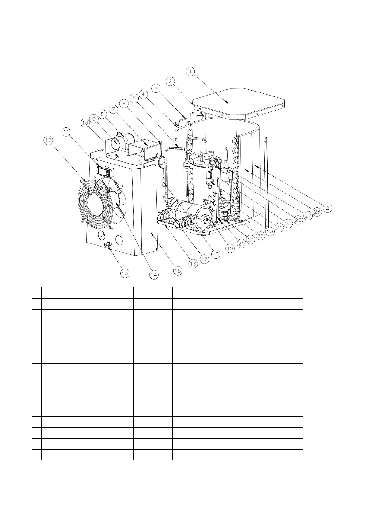
63
8. Schéma éclaté
Unité : HPM20
N°
Désignation
HPM20N°Désignation
HPM20
1
Panneau supérieur
108680024
16
Base
108680029
2
Pilier arrière gauche
108680018
17
Echangeur en titane
102040699
3
Sonde de température
117110079
18
Tube gaz
113100026
4
Tube gaz
113100027
19
Sonde température
117110068
5
Tube gaz
113010232
20
Support vanne gaz
108680007
6
Capillaire
109000090
21
Tube gaz
113050123
7
Coffret électrique
108680016
22
Vanne gaz
120000091
8
Clip de fixation
108010008
23
Tube gaz
113100008
9
Condensateur compresseur
111000038
24
Tube gaz
113020328
10
Panneau supérieur ventilateur
108680015
25
Sonde basse pression
116000017
11
Contrôleur
117020165
26
Tube gaz
109000048
12
Grille de protection ventilateur
108680017
27
Compresseur
101000191
13
Passe câble
142000126
28
Evaporateur
103000236
14
Support ventilateur
112000071
29
Câble électrique
139000050
15
Panneau avant
108680030
Page 67
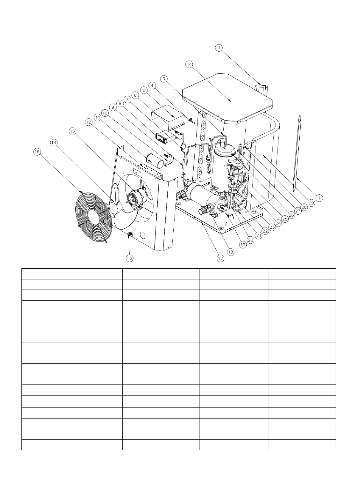
64
Unité : HPM30/HPM40
N°
Désignation
HPM30/40
N°
Désignation
HPM30/40
1
Pilier arrière gauche
108690009
16
Passe câble
142000126
2
Panneau supérieur
108690008
17
Base
108690020/108690022
3
Tube gaz
113010225/113010304
18
Echangeur en titane
102040700/102040746
4
Sonde de température ambiante
117110079
19
Sonde température
d’arrivée d’eau
117110068
5
Coffret électrique
108690015
20
Vanne gaz
120000091
6
Condensateur
111000034
21
Tube gaz
113050125
7
Capillaire
109000038/109000012
22
Tube gaz
108680007
8
Contrôleur
117020165
23
Tube gaz
113100008
9
Tube gaz
113420129
24
Tube gaz
109000048/109000043
10
Clip de fixation
108010006
25
Sonde basse pression
116000017
11
Condensateur compresseur
111300013/111000011
26
Compresseur
101000183/101000210
12
Panneau avant
108690021
27
Tube gaz
113020316/113020412
13
Moteur ventilateur
112000054/112000079
28
Tube gaz
113100027
14
Ventilateur
132000024
29
Evaporateur
103000237
15
Grille de protection ventilateur
108690005
30
Câble électrique
139000050
Page 68

65
9. Entretien
(1) Vous devez vérifier le circuit d’eau régulièrement pour éviter l'air entrant dans la tuyauterie et la présence
(4) Remplir entièrement le système avec de l'eau avant de faire fonctionner l’unité à nouveau.
(5) Lorsque l'unité est en cours de fonctionnement, il y aura toujours un peu d'eau de condensation qui se
de débit trop faible car cela réduirait les performances et la fiabilité de la pompe à chaleur.
(2) Nettoyez votre piscine et le système de filtration régulièrement.
(3) Vous devez évacuer l'eau de la pompe à chaleur si elle cesse de fonctionner longtemps (surtout en hiver).
décharge en dessous.
Page 69
66
Benutzer- und Wartungshandbuch
1. Technische Daten
2. Transport
3. Abmessungen
4. Einbau und Anschluss
5. Elektrische Verkabelung
6. Bedienung der Display-Steuerung
7. Fehlerbehebung
8. Explosionszeichnung
9. Wartung
ACHTUNG: Dieses Handbuch enthält alle notwendigen Informationen für den Gebrauch und die
Installation Ihrer Wärmepumpe.
Der Installateur muss das Handbuch lesen und die Anweisungen zur Installation und Wartung befolgen.
Der Installateur ist für die Installation des Produkts verantwortlich und sollte alle Anweisungen des
Herstellers und die geltenden Vorschriften befolgen. Eine falsche Installation führt zum Erlöschen der
Garantie.
Der Hersteller lehnt jede Verantwortung für Schäden durch Dritte, Objektingressionen und Fehler durch die
Installation ab, die nicht den Anweisungen entsprechen. Jede vom Hersteller nicht bestimmungsgemäße
Verwendung führt zum Erlöschen der Garantie.
INHALTSVERZEICHNIS
MINIWÄRMEPUMPE
Vielen Dank, dass Sie sich unsere Miniwärmepumpe für Ihren Pool verwenden, es erwärmt Ihr Poolwasser und
hält die Temperatur bei einer Luftumgebungstemperatur von über 12° C konstant.
Page 70
67
ACHTUNG
- Bewahren Sie die Wärmepumpe immer an einem gut belüfteten Ort und fern von allem, was einen Brand
verursachen kann, auf.
- Löten oder schweißen Sie das Rohr nicht, wenn sich Kältemittel in der Maschine befindet. Bitte füllen Sie
das Gas nicht auf, wenn Sie sich in einem engen Raum befinden.
- Bitte leeren Sie das Wasser in der Wärmepumpe immer im Winter oder wenn die Umgebungstemperatur
unter 0℃ sinkt, sonst wird der Titantauscher durch Einfrieren beschädigt, in diesem Fall erlischt Ihre
Garantie.
- Bitte trennen Sie immer die Stromversorgung, wenn Sie das Gehäuse öffnen wollen, um auf die
Wärmepumpe zuzugreifen.
- Bitte bewahren Sie den Display-Controller in einem trockenen Raum auf, um ihn vor Beschädigungen durch
Feuchtigkeit zu schützen.
- Die Maßnahmen zum Füllen von Gasen müssen von einem Fachmann mit R32-Betriebserlaubnis
durchgeführt werden.
Page 71
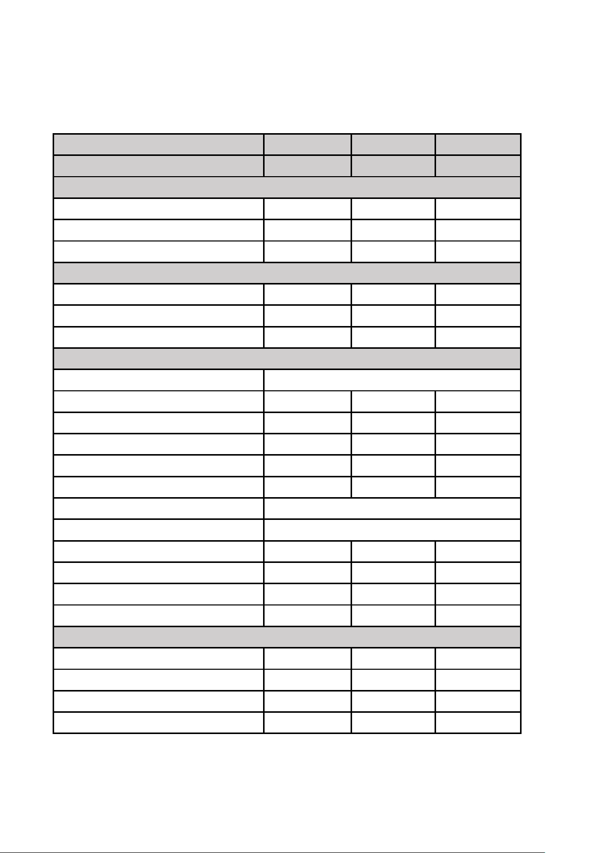
68
1. Technische Daten
1.1 Technische Daten zu Pool-Wärmepumpen
CE Standard, Gas R32.
Modell
HPM20
HPM30
HPM40
Code
71245
71258
71606
* Leistung bei Luft 28℃, Wasser 28℃, Luftfeuchtigkeit 80%
Heizkapazität (kW)
2.5
4.2
5.5
Leistungsaufnahme (kW)
0.59
1
1.31
COP
4.2
4.2
4.2
* Leistung bei Luft 15℃, Wasser 27℃, Luftfeuchtigkeit 70%
Heizkapazität (kW)
1.9
3.2
4.2
Leistungsaufnahme (kW)
0.56
0.91
1.2
COP
3.4
3.5
3.5
* Stromversorgung
Stromversorgung (V)
220-240V~50Hz/1PH
Betriebsstrom (A)
2.6
4.4
5.8
Mini- Sicherung (A)
7.51316
Empfohlenes Poolvolumen(m3)
0-10
5-16
10-20
Empfohlene Wasserströmung (m3/h)
222.5-3.2
Maximaler Druckverlust (Kpa)
151515
Kondensator
Titanium-Wärmetauscher
Wasserverbindung (mm)
38/32
Lüftergeschwindigkeit (rpm)
2500
1100
1100
Geräuschpegel at 10m dB(A)
484646
Geräuschpegel at 1m dB(A)
575555
Kältemitteltyp R32 (g)
150
290
450
*Abmessungen und Gewicht
Nettogewicht (kg)
182626
Verpackungsgewicht (kg)
19
28.5
28.5
Gesamtabmessungen (mm)
310*363.5*37
434*432.5*460
434*432.5*460
Verpackungsabmessungen (mm)
365*440*440
485*510*530
485*510*530
* Die obigen Daten können ohne vorherige Ankündigung geändert werden
Page 72
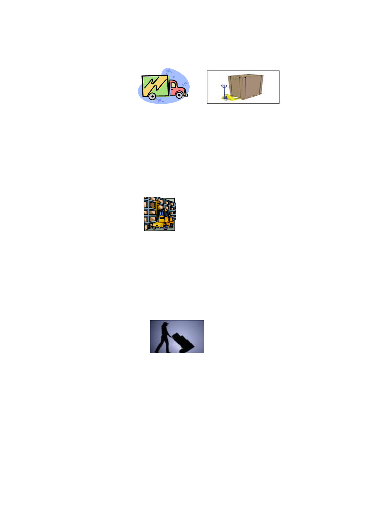
69
2. Transport
2.1 Produktlieferung und Verpackung
Für den Transport werden die Wärmepumpen auf der Palette fixiert und in einem Karton eingepackt.
Um diese vor Beschädigungen zu schützen, muss die Wärmepumpe in dieser Verpackung transportiert
werden.
Es liegt in der Verantwortung des Empfängers, Schäden, die während der Lieferung entstehen, innerhalb von
48 Stunden zu melden. Nach Übernahme des Geräts kann keine Verantwortung mehr übernommen werden.
2.2 Lagerung
* Das Lager sollte hell, geräumig, offen, gut belüftet, mit Lüftungsanlagen und ohne Brandquelle ausgestattet
sein.
* Wärmepumpen müssen in der Originalverpackung gelagert und vertikal transportiert werden. Ist dies nicht
der Fall, kann das Gerät erst nach Ablauf einer Mindestdauer von 24 Stunden betrieben werden, bevor es
eingeschaltet werden kann.
VERBOTEN
2.3 Transport zum endgültigen Aufstellungsort
* Beim Auspacken des Produkts und beim Transport von der Palette zum endgültigen Aufstellungsort ist es
notwendig, die Wärmepumpe in einer vertikalen Position zu halten.
* Rauchen und Flammen sind in der Nähe der R32-Maschine verboten.
Der Wasseranschluss darf nicht als Lastaufnahmemittel verwendet werden, der Hersteller übernimmt keine
Verantwortung.
Nachdem alle Verbindungen hergestellt und überprüft wurden, führen Sie die folgenden Schritte aus:
1.SSchalten Sie die Filterpumpe ein. Überprüfen Sie diese auf Undichtigkeiten und stellen Sie sicher, dass das
Wasser zum und vom Schwimmbad fließt.
Page 73
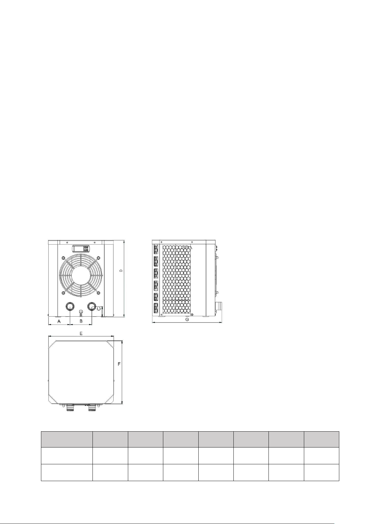
70
2.SSchließen Sie die Stromversorgung der Wärmepumpe an und drücken Sie die Ein-/Aus-Taste auf dem
3. Abmessungen
Modelle/ (mm)
ABCDEFG
HPM20
90.4
13050375
310
300
363.5
HPM30/HPM40
116.5
20050460
434
365
432.5
elektronischen Bedienfeld. Das Gerät startet nach Ablauf der Zeitverzögerung (siehe unten).
3.Überprüfen Sie nach einigen Minuten, ob die aus dem Gerät austretende Luft kühler ist.
4. Wenn die Filterpumpe ausgeschaltet ist, sollte sich das Gerät auch automatisch ausschalten.
5.Lassen Sie die Wärmepumpe und die Filterpumpe 24 Stunden am Tag laufen, bis die gewünschte
Wassertemperatur erreicht ist. Die Wärmepumpe stoppt bei +1°C. Danach wird sie automatisch neu gestartet
(solange die Filterpumpe läuft), wenn die Wassertemperatur im Schwimmbad um 1 Grad unter die eingestellte
Temperatur fällt (z.B. wenn Sie die Temperatur 28°C einstellen, stoppt die Wärmepumpe bei einer Temperatur
von 29°C. Sie läuft wieder an, wenn die Wassertemperatur auf 27°C sinkt.)
Abhängig von der anfänglichen Wassertemperatur im Pool und der Lufttemperatur kann es unter Umstände
einige Tage dauern, bis das Wasser die gewünschte Temperatur erreicht hat. Eine gute
Schwimmbadabdeckung kann die erforderliche Zeitspanne erheblich verkürzen.
* bei Schäden an den Wasserleitungen.
Page 74
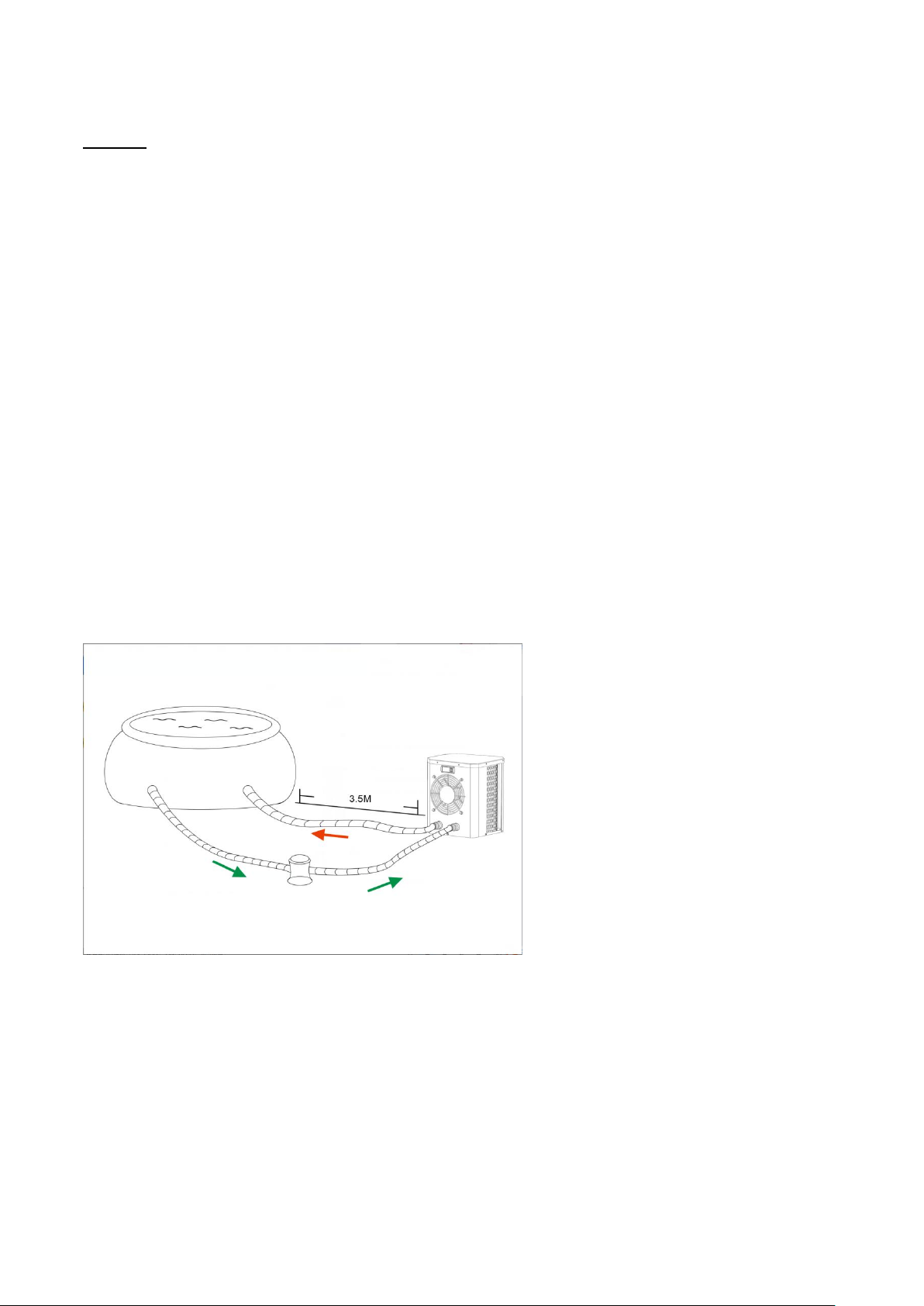
71
4. Einbau und Anschluss
Achtung:
Bitte beachten Sie bei der Installation der Wärmepumpe die folgenden Regeln:
1. Die Zugabe von Chemikalien muss in den der Wärmepumpe nachgeschalteten Rohrleitungen erfolgen.
2. Halten Sie die Wärmepumpe immer aufrecht. Wenn das Gerät in einem Winkel gehalten wurde, warten
Sie mindestens 24 Stunden, bevor Sie die Wärmepumpe mit Netzstrom versorgen.
4.1 Positionierung der Wärmepumpe
Das Gerät funktioniert an jeder gewünschten Stelle einwandfrei, solange die folgenden drei Punkte vorhanden
sind:
1. Frische Luft – 2. Elektrizität – 3. Schwimmbeckenfilter
Das Gerät kann an nahezu jedem Außenstandort installiert werden, solange die vorgeschriebenen
Mindestabstände zu anderen Objekten eingehalten werden (siehe Zeichnung unten). Für die Installation in
einem Hallenbad wenden Sie sich bitte an Ihren Installateur. Die Installation an einem windigen Ort stellt kein
Problem dar.
ACHTUNG: Installieren Sie das Gerät niemals in einem geschlossenen Raum mit einem begrenzten
Luftvolumen, in dem die aus dem Gerät austretende Luft wiederverwendet wird, oder in der Nähe von
Sträuchern, die den Lufteinlass blockieren könnten. Solche Stellen beeinträchtigen die kontinuierliche
Frischluftzufuhr, was zu einem verminderten Wirkungsgrad führt und möglicherweise eine ausreichende
Wärmeleistung verhindert.
Page 75
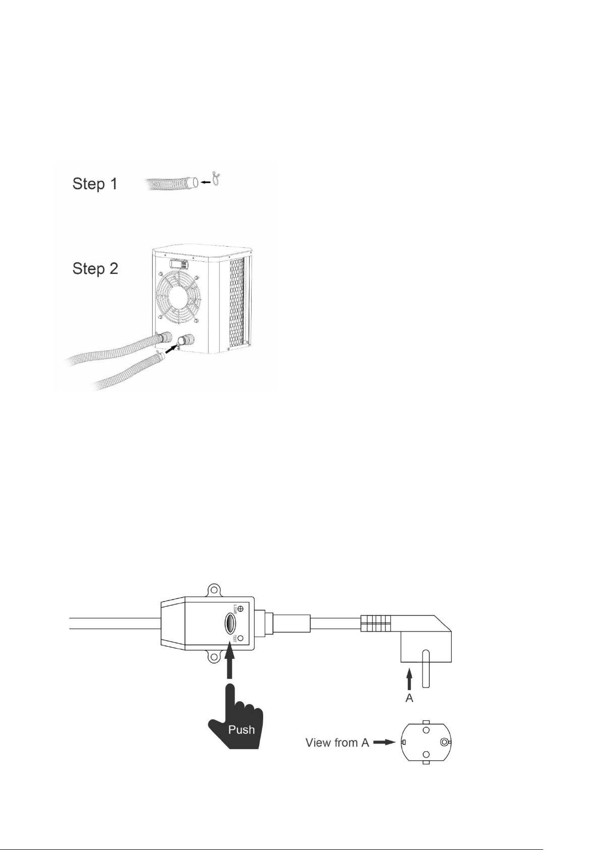
72
4.2 Erstinbetriebnahme
Hinweis: Um das Wasser im Pool (oder Whirlpool) zu erwärmen, muss die Pumpe so laufen, dass das
Wasser durch die Wärmepumpe zirkuliert. Die Wärmepumpe läuft nicht an, wenn das Wasser nicht
zirkuliert.
4.3 Schlauchverbindung
Anmerkung:
Das Werk liefert nur die Wärmepumpe. Alle anderen Komponenten, einschließlich zweier Schläuche, müssen
vom Benutzer oder vom Installateur bereitgestellt werden.
4.4 Stromanschluss
Vergewissern Sie sich vor dem Anschließen des Gerätes, dass die Versorgungsspannung mit der
Betriebsspannung der Wärmepumpe übereinstimmt. Der RCD-Stecker wurde mit dem Netzkabel mitgeliefert,
das einen elektrischen Schutz bieten kann.
Page 76
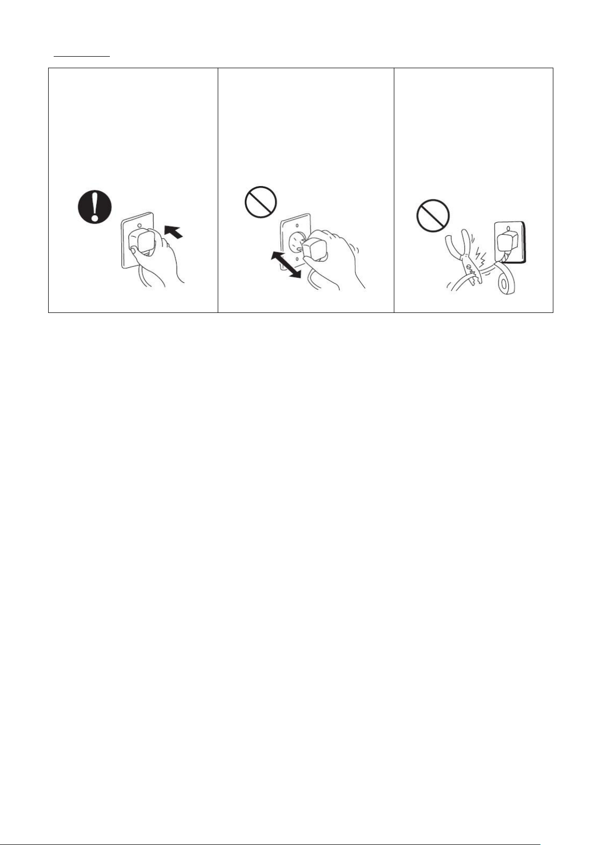
73
Anmerkung:
Stellen Sie sicher, dass der
Netzstecker fest sitzt
Wenn der Stecker nicht sicher ist,
kann dies einen elektrischen Schlag,
Überhitzung oder Feuer
verursachen
Ziehen Sie niemals den Netzstecker
während des Betriebs heraus
Andernfalls kann es aufgrund von
Überhitzung zu einem Stromschlag
oder Feuer
kommen.
Verwenden Sie niemals
beschädigte elektrische Kabel
oder nicht spezifizierte
elektrische Kabel.
Andernfalls kann es zu einem
Stromschlag oder einem Brand
kommen.
Nachdem alle Verbindungen hergestellt und überprüft wurden, führen Sie die folgenden Schritte aus:
6. Schalten Sie die Filterpumpe ein. Überprüfen Sie auf Undichtigkeiten und stellen Sie sicher, dass das
Wasser zum und vom Schwimmbad fließt.
7. Schließen Sie die Stromversorgung der Wärmepumpe an und drücken Sie die Ein-/Aus-Taste auf dem
elektronischen Bedienfeld. Das Gerät startet nach Ablauf der Zeitverzögerung (siehe unten).
8. Überprüfen Sie nach einigen Minuten, ob die aus dem Gerät austretende Luft kühler ist.
9. Wenn die Filterpumpe ausgeschaltet ist, sollte sich das Gerät auch automatisch ausschalten.
10. Lassen Sie die Wärmepumpe und die Filterpumpe 24 Stunden am Tag laufen, bis die gewünschte
Wassertemperatur erreicht ist. Die Wärmepumpe stoppt bei +1°C. Danach wird sie automatisch neu gestartet
(solange die Filterpumpe läuft), wenn die Wassertemperatur im Schwimmbad um 1 Grad unter die eingestellte
Temperatur fällt (z.B. wenn Sie die Temperatur 28°C einstellen, stoppt die Wärmepumpe bei einer Temperatur
von 29°C. Sie läuft wieder an, wenn die Temperatur des Wassers auf 27°C sinkt.)
Abhängig von der anfänglichen Wassertemperatur im Schwimmbad und der Lufttemperatur kann es mehrere
Tage dauern, bis das Wasser die gewünschte Temperatur erreicht ist. Eine gute Schwimmbadabdeckung kann
die erforderliche Zeitspanne erheblich verkürzen.
Page 77
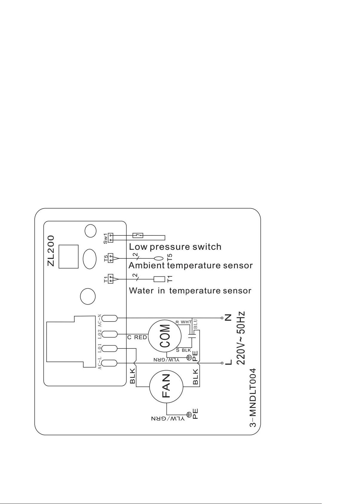
74
Zeitverzögerung - Die Wärmepumpe verfügt über eine eingebaute 3-minütige Anlaufverzögerung, um die
5. Verkabelung
Schaltung zu schützen und übermäßigen Verschleiß des elektrischen Schützes zu vermeiden. Nach Ablauf
dieser Zeitspanne startet das Gerät automatisch neu. Schon eine kurze Stromunterbrechung löst diese
Zeitverzögerung aus und verhindert einen sofortigen Neustart des Gerätes. Zusätzliche Stromunterbrechungen
während dieser Verzögerungszeit haben keinen Einfluss auf die 3-minütige Dauer der Verzögerung.
4.5 Kondensation
Die in die Wärmepumpe angesaugte Luft wird durch den Betrieb der Wärmepumpe zur Erwärmung des
Beckenwassers gekühlt, was zu Kondensation an den Lamellen des Verdampfers führen kann. Die
Kondensationsmenge kann bei hoher Luftfeuchtigkeit bis zu mehreren Würfen pro Stunde betragen. Das
Kondenswasser wird vom Boden der Wärmepumpe abfließen. Dies wird manchmal fälschlicherweise als
Wasserleck angesehen.
5.1 ELEKTROLEITPLAN DER POOL-WÄRMEPUMPE
HPM20
Page 78
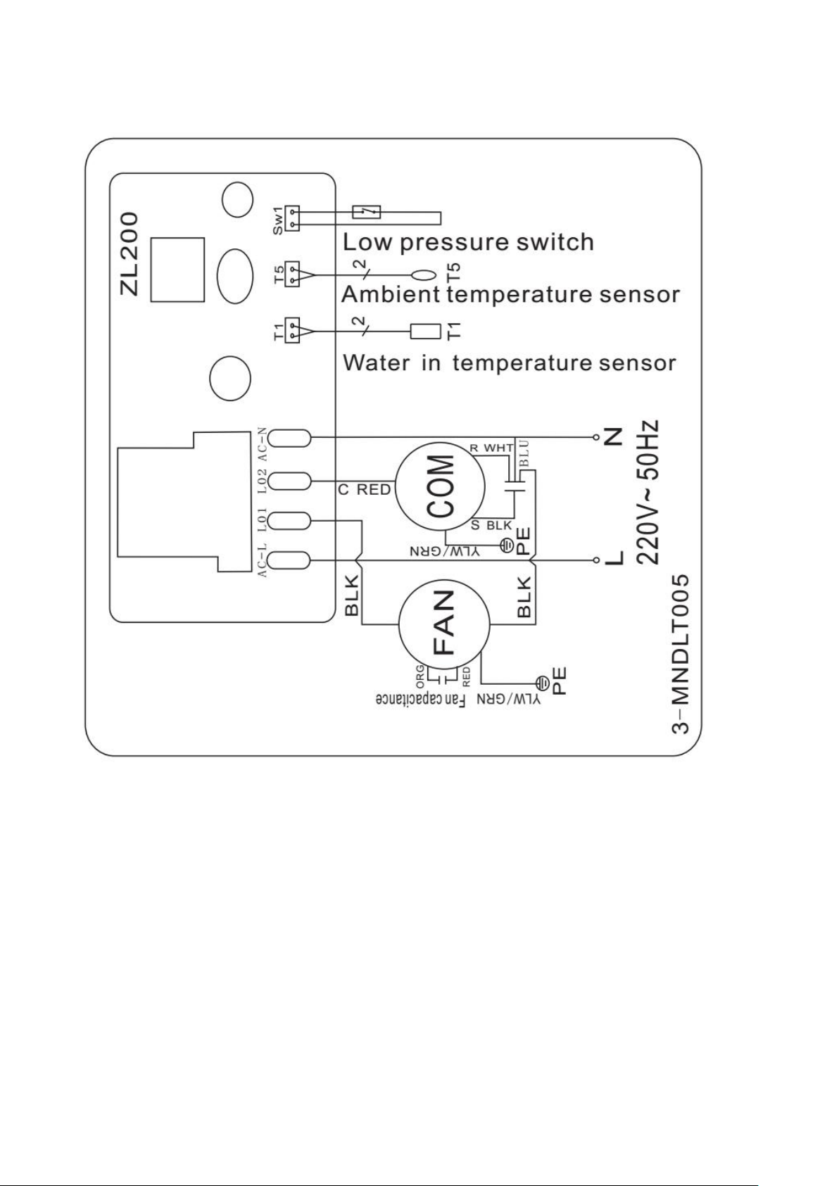
75
5.2 ELEKTROLEITPLAN DER POOL-WÄRMEPUMPE
HPM30/HPM40
ANMERKUNG:
(1) Oberhalb des elektrischen Schaltplans nur zu Ihrer Information, bitte beachten Sie das Maschinenschild für
den Schaltplan.
(2) Die Pool-Wärmepumpe muss an eine Erdleitung angeschlossen werden, obwohl der Wärmetauscher der
Einheit vom Rest der Einheit galvanisch getrennt ist. Die Erdung des Geräts ist weiterhin erforderlich, um Sie
vor Kurzschlüssen im Inneren des Geräts zu schützen. Außerdem ist eine Verklebung erforderlich.
Trennung: Ein Mittel zum Trennen sollte sich in Sichtweite des Geräts befinden und leicht zugänglich von
diesem aus zugänglich sein (Leistungsschalter, abgesicherter oder ungesicherter Schalter). Dies ist bei
gewerblichen und privaten Wärmepumpen üblich. Es verhindert die Fernaktivierung unbeaufsichtigter Geräte
und ermöglicht das Abschalten der Stromversorgung am Gerät während der Wartung des Geräts.
Page 79
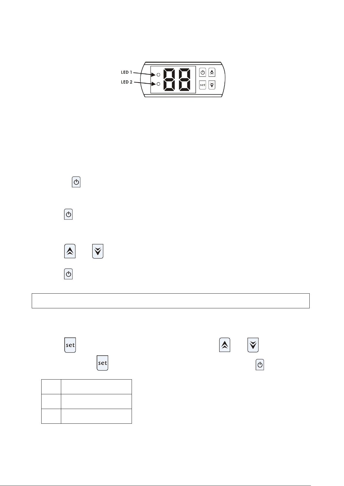
76
6. Bedienung des Display-Controllers
6.1 Die Tasten der LED-Kabelsteuerung
Achtung: Die Pumpe kann nur dann arbeiten, wenn das Wasserzirkulations- und Filtersystem arbeitet.
Code
Parameter
d0
Umgebungstemperatur
d1
Wassertemperatur
Wenn die Wärmepumpe läuft, dann zeigt der LED Bildschirm die Wassereintrittstemperatur.
LED 1 leuchtet, wenn der Kompressor läuft.
LED 2 leuchtet bei Problemen.
6.2 Starten oder Stoppen Sie die Wärmepumpe
Drücken Sie , um die Wärmepumpe zu starten. Der LED-Bildschirm zeigt die gewünschte
Wassertemperatur für 5 Sekunden, und dann die Wassereintrittstemperatur.
Drücken Sie , um die Wärmepumpe zu deaktivieren.
6.3 Wassertemperatureinstellung
Drücken Sie und , um die gewünschte Wassertemperatur einzustellen (10—42℃)
Drücken Sie erneut, um die neuen Einstellungen zu speichern.
6.4 Wie sie die Parameter überprüfen
Drücken Sie ,es wird die Parameterprüfung eingeben, drücken Sie und um den Code d0 / d1
zu wählen,Drücken Sie , es zeigt den gemessenen Wert an. Zuletzt drücken Sie zum Beenden.
Hinweis: Die Parameterdaten können nicht von Endbenutzern festgelegt werden.
Page 80

77
7. Fehlerbehebung
7.1 Fehlercodeanzeige auf einer LED-Kabelsteuerung
Zu niedriger oder zu hoher
Schutz der
Umgebungstemperatur
P0
1. Die Umgebungstemperatur
liegt außerhalb des
Betriebsbereichs: 12℃- 42℃.
2. Steuerungsfehler
1. Warten Sie, bis die
Umgebungstemperatur auf 13 ° C
ansteigt oder auf 40 ° C abkühlt, um
den Neustart zu starten.
2. Ersetzen Sie den Controller.
Wassertemperatursensor-F
ehler
P1
Wassertemperatursensor
Unterbrechung oder
Kurzschluss.
Ersetzen Sie den
Wassertemperatursensor.
Ausfall des
Umgebungstemperatursen
sors
P2
Umgebungstemperatursensor
Unterbrechung oder
Kurzschluss.
Ersetzen Sie den
Umgebungstemperatursensor.
Niederdruckschutz
EL
1. Niederdruckschalter nicht
angeschlossen oder defekt.
2. Ausströmen von Gas.
Es muss von den professionellen
Technikern repariert werden.
Page 81

78
7.2 Andere Fehlfunktionen und ihre Lösung (werden nicht auf der LED-Kabelsteuerung angezeigt)
Fehlfunktion
Anzeichen
Ursachen
Lösung
Wärmepumpe
läuft nicht
LED-Kabelsteuerung hat
keine Anzeige.
Keine Stromzufuhr
Check cable and circuit breaker if it
is connected.
LED-Kabelsteuerung
zeigt die aktuelle
Wassertemperatur an.
1. Wassertemperatur erreicht den
vorgesehenen Wert, HP ist auf
konstantem Temperaturniveau
2. Wärmepumpe hat erst zu
arbeiten angefangen
1. Überprüfen Sie die
Wassertemperatureinstellungen.
2. Starten Sie die Wärmepumpe
nach ein paar Minuten.
Kurze Laufzeiten
LED-Bildschirm zeigt
aktuelle
Wassertemperatur an,
kein Fehlercode wird
angezeigt.
1. Ventilator läuft nicht
2. Luftzirkulation ist nicht
ausreichend.
3. Unzureichende Kühlmittel.
1. Überprüfen Sie die
Kabelverbindungen zwischen dem
Motor und dem Ventilator. Wenn
nötig sollten Sie ersetzt werden.
2. Überprüfen Sie die Position der
Wärmepumpeneinheit, und
entfernen Sie alle Hindernisse um
eine optimale Luftzirkulation zu
erreichen.
3 Ersetzen oder reparieren Sie die
Wärmepumpeneinheit.
Wasserflecken
Wasserflecken auf der
Wärmepumpeneinheit
1. Beton.
2. Wasserlecke.
1. Nichts tun.
2. Überprüfen Sie den
Luft-Wärmewechsle auf Defekte.
Page 82
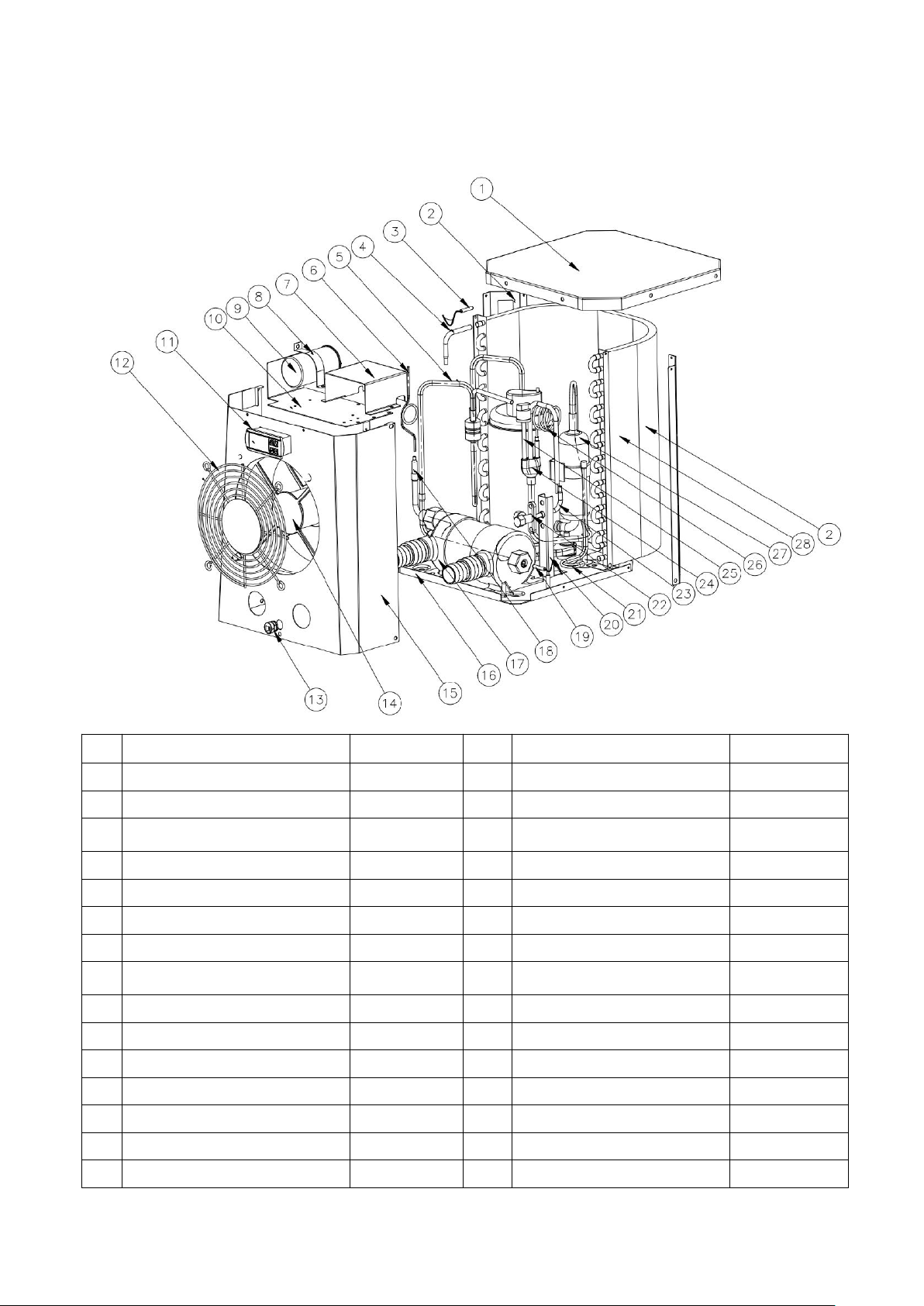
79
8. Explosionszeichnung
Gerät: HPM20
Nr.
Bezeichnung der Teile
HPM20
Nr.
Bezeichnung der Teile
HPM20
1
Obere Abdeckung
108680024
16
Base
108680029
2
Säule
108680018
17
Titanaustauscher
102040699
3
Umgebungstemparatur. Sensor
117110079
18
Kupferrohr
113100026
4
Kupferrohr
113100027
19
Wasser in Temp. Sensor
117110068
5
Abgasrohr
113010232
20
Kugelventilplatte
108680007
6
Kapillar
109000090
21
Gassammelrohr
113050123
7
Elektrische Box
108680016
22
Globales Ventil
120000091
8
Kompressor-Kapazitätsklemme
108010008
23
Kupferrohr
113100008
9
Verdichterkapazität
111000038
24
Gasrückführung
113020328
10
Lüftermotorplatte
108680015
25
Niederdruckschalter
116000017
11
Regler
117020165
26
Durchgangsventilkapillare
109000048
12
Kühlergrill
108680017
27
Kompressor
101000191
13
Netzkabelschnalle
142000126
28
Verdampfer
103000236
14
Lüftermotor-Baugruppe
112000071
29
Stromkabel
139000050
15
Frontblende
108680030
Page 83
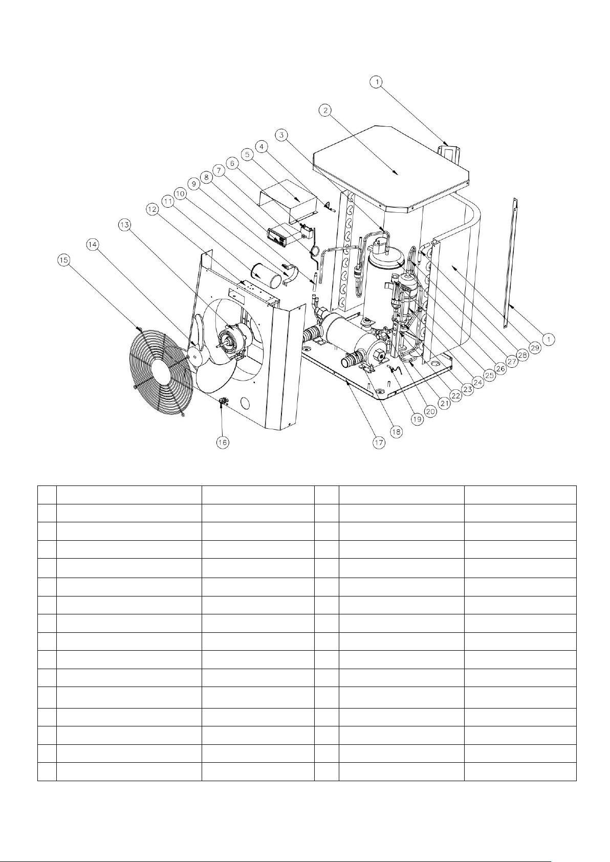
80
Gerät: HPM30/HPM40
Nr.
Ersatzteile
HPM30/40
Nr.
Ersatzteile
HPM30/40
1
Säule
108690009
16
Netzkabelschnalle
142000126
2
Obere Abdeckung
108690008
17
Base
108690020/108690022
3
Abgasrohr
113010225/113010304
18
Titanaustauscher
102040700/102040746
4
Umgebungstemparatur. Sensor
117110079
19
Wasser in Temp. Sensor
117110068
5
Elektrische Box
108690015
20
Globales Ventil
120000091
6
Lüfterkondensator
111000034
21
Gassammelrohr
113050125
7
Kapillar
109000038/109000012
22
Absperrventilplatte
108680007
8
Regler
117020165
23
Kupferrohr
113100008
9
Kupferrohr
113420129
24
Durchgangsventilkapillare
109000048/109000043
10
Kompressor-Kapazitätsklemme
108010006
25
Niederdruckschalter
116000017
11
Verdichterkapazität
111300013/111000011
26
Kompressor
101000183/101000210
12
Frontplatte montieren
108690021
27
Gasrückführung
113020316/113020412
13
Lüftermotor
112000054/112000079
28
Kupferrohr
113100027
14
Ventilatorflügel
132000024
29
Verdampfer
103000237
15
Kühlergrill
108690005
30
Stromkabel
139000050
Page 84

81
9.Wartung
(1) Sie sollten das Wasserversorgungssystem regelmäßig überprüfen, um zu verhindern, dass Luft in das
System eindringt und ein niedriger Wasserdurchfluss entsteht, da dies die Leistung und Zuverlässigkeit des
HD-Gerätes beeinträchtigen würde.
(2) Reinigen Sie Ihre Becken und Ihr Filtersystem regelmäßig, um Schäden am Gerät zu vermeiden.
(3) Sie sollten das Wasser aus der Wärmepumpe ablassen, wenn es für längere Zeit (insbesondere in der
Wintersaison) nicht mehr läuft.
(4) Überprüfen Sie den Wasserstand vor dem Start des Gerätes nach einer längeren Nutzungspause.
(5) Wenn das Gerät in Betrieb ist, tritt Kondensat aus dem Boden des Gerätes aus. Das ist normal.
Page 85
82
INDICE
1. Specifiche
2. Trasporto
3. Dimensioni
4. Installazione e collegamento
5. Cablaggio elettrico
6. Controller display di funzionamento
7. Risoluzione dei problemi
8. Esplosi
9. Manutenzione
ATTENTION: Il presente manuale comprende tutte le informazioni necessarie all’utilizzo e all’installazione
della vostra pompa di calore.
L’installatore deve leggere attentamente il manuale e seguire le istruzioni per la messa in funzione e la
manutenzione.
L’installatore è responsabile dell’installazione del prodotto e deve seguire tutte le istruzioni del produttore e
regolamenti in vigore. Un’errata installazione porterà alla nullità della garanzia.
Il produttore declina ogni responsabilità per danni causati a terzi, infiltrazioni di oggetti ed errori dovuti a un
mancato rispetto delle linee guida. Ogni uso che differisca da quello inteso dal produttore condurrà
all’invalidazione della garanzia.
MINI HEATER
Manuale di Uso e Manutenzione
Grazie per aver scelto Mini Heater per riscaldare la vostra piscina, riscalderà l’acqua e manterrà costante la
temperatura con una temperatura dell’aria superiore ai 12°C.
Page 86

83
WARNING
- Non operare saldature sui tubi se vi è ancora del gas refrigerante all’interno dell’apparecchiatura. Si prega
- Svuotare sempre l’acqua presente all’interno della pompa di calore nel periodo invernale o quando la
- Interrompere l’alimentazione elettrica quando si desidera aprire l’apparecchiature per raggiungere la
- Conservare il controller del display in un luogo asciutto per proteggerlo dai danni dell’umidità.
- Il riempimento di gas deve essere effettuato da un professionista con licenza per l’uso di gas R32.
- Tenere sempre la pompa in un luogo ben ventilato e lontano da ogni possibile causa di incendio.
di non effettuare una ricarica di gas in luoghi angusti o poco ventilati.
temperatura ambiente scende al di sotto degli 0℃, in caso contrario lo scambiatore in titanio potrà
risultare danneggiato a causa del congelamento, in tal caso, decadrà il diritto alla garanzia.
parte interna della pompa di calore.
Page 87
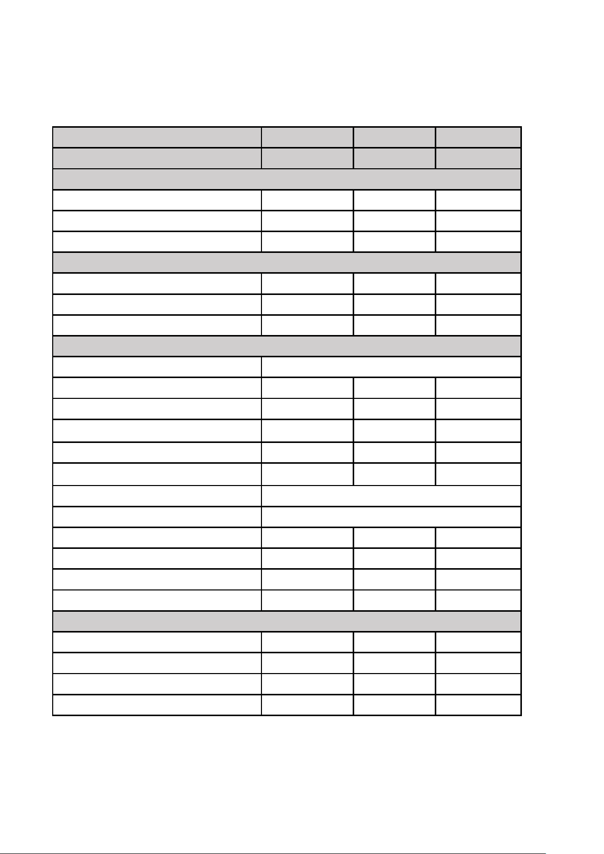
84
1. Specifiche
1.1 Dati tecnici per pompe di calore per piscine
Normativa CE, gas R32.
Articolo
HPM20
HPM30
HPM40
Codice
71245
71258
71606
* Capacità di riscaldamento con Aria a 28°C, Acqua a 28°C, Umidità all’80%
Produzione di calore (kW)
2.5
4.2
5.5
Consumo energetico (kW)
0.59
1
1.31
COP
4.2
4.2
4.2
* Capacità di riscaldamento con Aria a 15°C, Acqua a 26°C, Umidità al 70%
Produzione di calore (kW)
1.9
3.2
4.2
Consumo energetico (kW)
0.56
0.91
1.2
COP
3.4
3.5
3.5
* Dato generali
Voltaggio (V)
220-240V~50Hz/1PH
Corrente nominale (A)
2.6
4.4
5.8
Fusibile di protezione (A)
7.51316
Volume consigliato della piscina (m3)
0-10
5-16
10-20
Portata d’acqua consigliato (m3/h)
2
2
2.5-3.2
Caduta di pressione dell’acqua (Kpa)
151515
Condensatore
Scambiatore in titanio in PVC
Tubo di entrata-uscita dell’acqua (mm)
38/32
Velocità del ventilatore (rpm)
2500
1100
1100
Pressione sonora (10m) dB(A)
484646
Pressione sonora (1m) dB(A)
575555
Carica in g di gas refrigerante (R32)
150
290
450
* Dimensioni/Peso
Peso netto (kg)
182626
Peso lordo (kg)
19
28.5
28.5
Dimensioni nette (mm)
310*363.5*375
434*432.5*460
434*432.5*460
Dimensioni dell’imballo (mm)
365*440*440
485*510*530
485*510*530
* Le succitate specifiche possono essere soggette a modifica senza previa comunicazione.
Page 88
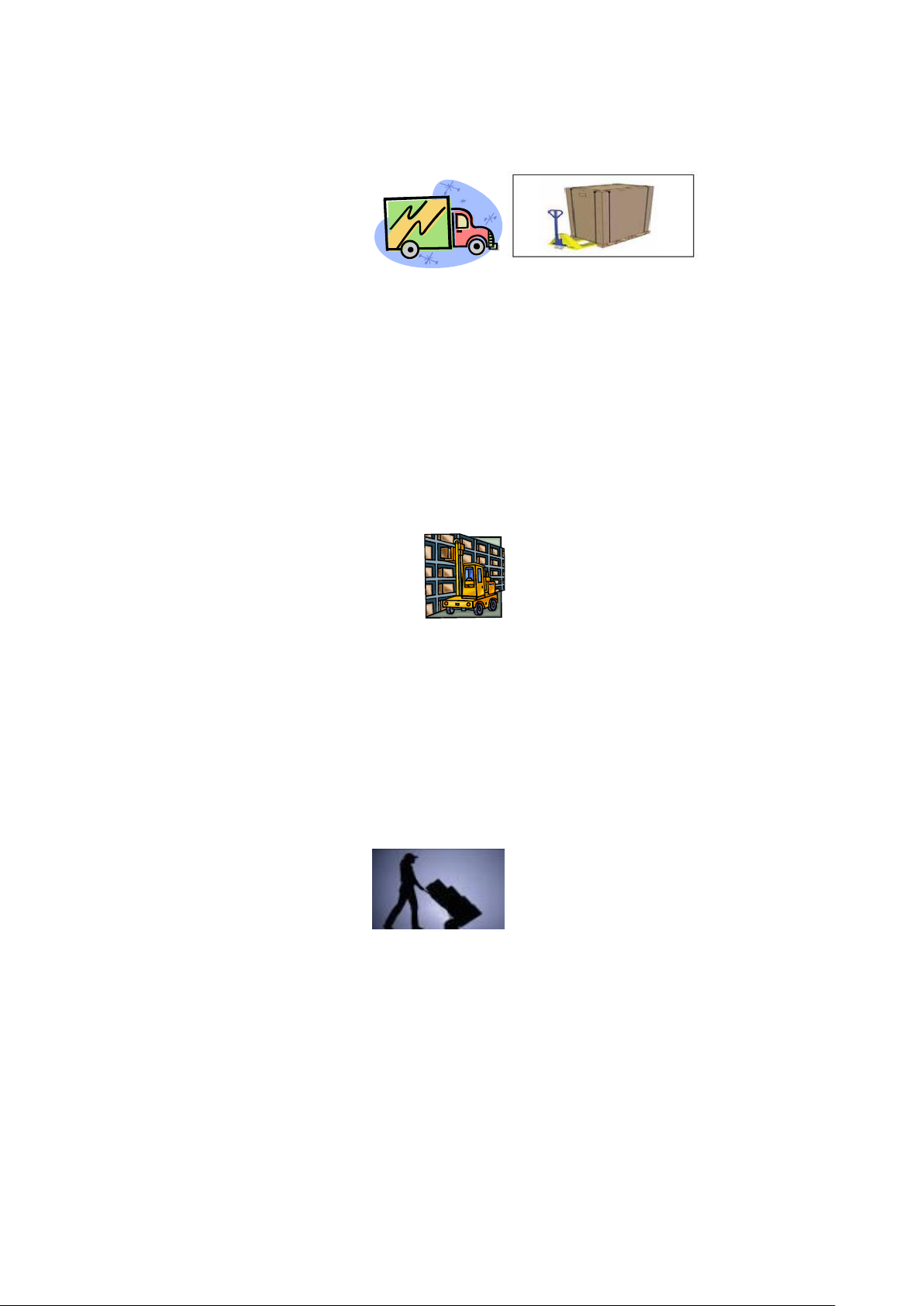
85
2. Trasporto
2.1 Consegna dell’imballo
Per essere trasportate, le pompe di calore vengono fissate su un pallet e imballate con una scatola di cartone.
2.2 Stoccaggio
* Il magazzino deve essere luminoso, spazioso, aperto, ben ventilato, deve disporre di sistema per la
* Le pompe di calore devono essere immagazzinate e movimentate in posizione verticale utilizzando il loro
* Durante le operazioni per disimballare il prodotto e durante il suo trasferimento dal pallet al luogo di
* È vietato fumare e utilizzare fiamme libere in prossimità di un’apparecchiatura che funzioni a R32.
Per proteggerle da qualsiasi tipo di danno, la pompa di calore deve essere movimentata unitamente al proprio
imballo.
È responsabilità in capo al destinatario notificare qualsiasi danno occorso durante la consegna. La notifica deve
essere apposta, sotto forma di riserva motivata, sul ddt di consegna. Per i danni occulti, da notificare entro 8
giorni dal ricevimento, fare riferimento al Codice Civile. Non verrà assunta alcuna responsabilità dopo che l’unità
è stata accettata.
ventilazione ed essere privo di fonti di ignizione.
imballo originale. Se ciò non avviene, è necessario che siano trascorse 24 ore prima che le unità possano
essere collegate all’alimentazione e accese.
VIETATO
2.3 Movimentazione alla posizionedefinitiva
definitiva installazione, è necessario mantenere la pompa di calore in posizione verticale.
Il collegamento idrico non deve essere utilizzato come maniglia di carico. ll produttore non si assumerà alcuna
responsabilità in caso di danni alle tubature dellacqu.
Page 89
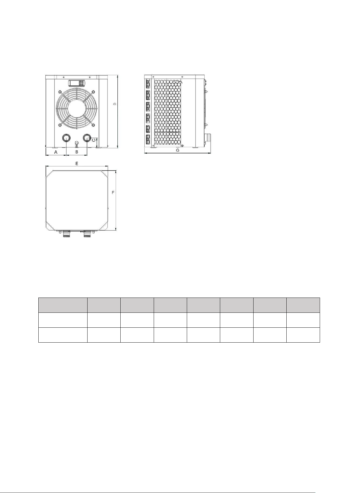
86
3. Dimensioni
Articolo / (mm)
ABCDEFG
HPM20
90.4
13050375
310
300
363.5
HPM30/HPM40
116.5
20050460
434
365
432.5
Page 90
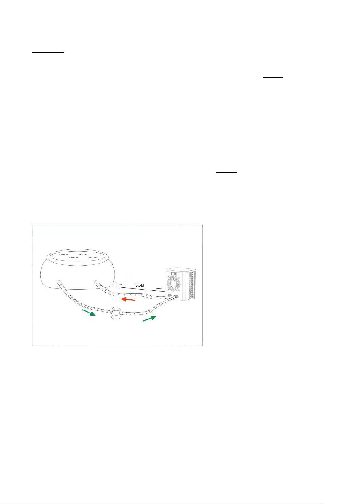
87
4. Installazione e collegamento
Attenzione:
1. Qualsiasi aggiunta di prodotti chimici deve avvenire nella tubatura che si trova a valle della pompa di
2. Tenete sempre la pompa di calore in posizione verticale. Se l’unità è stata inclinata, attendete almeno
4.1 Posizionamento della pompa di calore
4.2 Funzionamento iniziale
Quando si installa la pompa di calore, si prega di osservare le seguenti indicazioni:
calore .
24 ore prima di alimentare elettricamente la pompa di calore.
L’unità funzionerà adeguatamente in qualsiasi auspicata posizione laddove siano presenti i seguenti tre fattori:
1. Aria pulita – 2. Elettricità – 3. Filtri per piscina
In linea di principio, l’unità può essere installata in qualsiasi luogo all’esterno sempre e quando vengano
mantenute le distanze minime stabilite rispetto agli altri oggetti (cfr. disegno a seguire). Si prega di consultare
il proprio installatore per un’installazione in una piscina coperta. Eventuali installazioni in luoghi ventosi non
presentano alcun tipo di problema.
ATTENZIONE: Mai installare l’unità in una stanza chiusa con un volume d’aria limitato in cui l’aria espulsa
dall’unità venga riutilizzata, o in prossimità di siepi che potrebbero bloccare l’entrata dell’aria. Tali posizioni
compromettono la fornitura continuativa di aria pulita, avendo come risultanza una ridotta efficienza e
impedendo potenzialmente una sufficiente produzione di calore.
Per scaldare l’acqua presente nella piscina (o in una vasca idromassaggio), la pompa della piscina deve
essere in funzionamento di modo che l’acqua circoli nella pompa di calore. La pompa di calore non si avvierà
se l’acqua non sta circolando.
Page 91
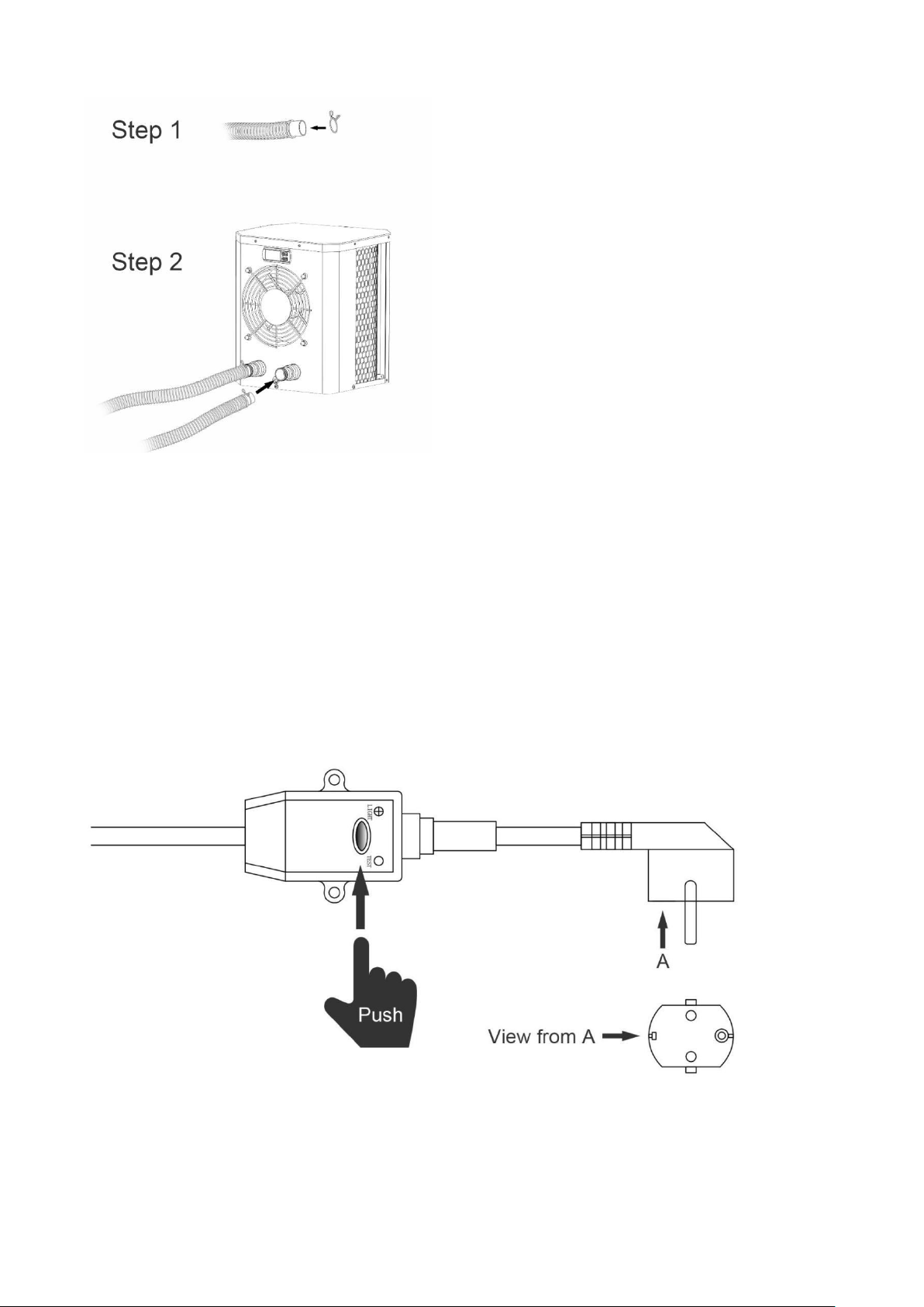
88
4.3 Collegamento del tubo
Nota:
4.4 Collegamento elettrico
La fabbrica fornisce solo la pompa di calore. Tutti gli altri componenti, compresi i due tubi, devono essere forniti
dall’utente o dall’installatore.
Prima di collegare l’unità, controllare che l’alimentazione sia corretta per il voltaggio per cui è progettata la
pompa di calore. La spina RCD è stata fornita con il suo cavo di alimentazione, il che può offrire una
protezione elettrica.
Page 92
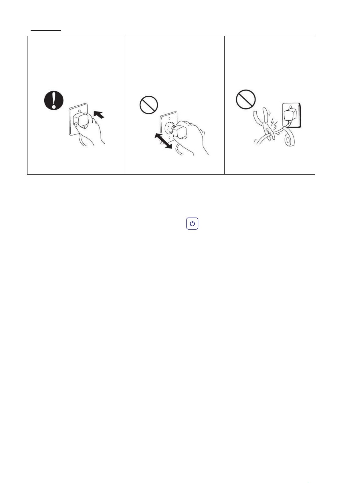
89
Attenzione:
Accertatevi che la spina sia sicura
Non togliere mai la spina in corso di
Non usare mai cavi elettrici
Se la spina non è sicura, può causare
funzionamento
danneggiati o non rispondenti
alle specifiche
folgorazione, surriscaldamento
Ciò potrebbe essere causa di
Ciò potrebbe essere causa di
o incendi
folgorazione o di un incendio da
surriscaldamento.
folgorazione o incendio.
1. Accendere la pompa a filtro. Controllare la presenza di eventuali perdite e verificare che l’acqua stia fluendo
2. Alimentare la pompa di calore e premete il tasto On/Off sul pannello di controllo. L’unità si avvierà
3. Dopo pochi minuti, verificare che l’aria emessa dall’unità sia più fredda.
4. Quando la pompa di filtrazione viene spenta, anche l’unità dovrebbe spegnersi automaticamente.
5. Consentire alla pompa di calore e alla pompa di filtrazione di funzionare 24 ore su 24 fino a che non sia
Una volta effettuati e verificati tutti i collegamenti, effettuare la seguente procedura:
da e per la piscina.
una volta conclusosi il tempo di ritardo programmato(vedi sotto).
raggiunta la temperatura dell’acqua desiderata(primo riscaldamento). La pompa di calore cesserà di
funzionare una volta raggiunta detta temperatura +1°C. Una volta avvenuto ciò, si riavvierà automaticamente
(sempre e quando la pompa di filtrazione stia funzionando) qualora la temperatura dell’acqua della piscina
dovesse scendere di 1 grado al di sotto della temperatura fissata (per esempio, se fissate la temperatura a
28°C, la pompa di calore si arresterà quando la temperatura sarà a 29°C.Mentre si riavvierà quando la
temperatura dell’acqua scenderà a 27°C)
Dipendendo dalla temperatura iniziale dell’acqua presente nella piscina e dalla temperatura dell’aria,
potrebbero occorrere diversi giorni per riscaldare l’acqua fino alla temperatura desiderata. Una buona
copertura della piscina può ridurre significativamente la lunghezza del periodo di tempo richiesto.
Ritardo di accesione – La pompa di calore ha un ritardo in avvio incorporato di 3 minuti per evitare una
eccessiva sollecitazione del contattore elettrico. L’unità si riavvierà automaticamente una volta trascorso
questo ritardo. Anche una breve interruzione di corrente attiverà questo ritardo di tempo ed evitare
l’immediato riavvio dell’unità. Ulteriori interruzioni dell’alimentazione durante questo periodo di ritardo di
tempo non influiranno sulla durata di 3 minuti del ritardo.
Page 93

90
4.5 Condensa
L’aria aspirata all’interno della pompa di calore è raffreddata dal funzionamento della pompa di calore che sta
riscaldando l’acqua della piscina, il che può generare condensa sulle alette dell’evaporatore.
In caso di elevata umidità, la quantità di condensa può essere anche di diversi litri all’ora. La condensa verrà
drenata dalla base della pompa di calore. Questo fatto viene talora erroneamente considerata una perdita
d’acqua.
Page 94
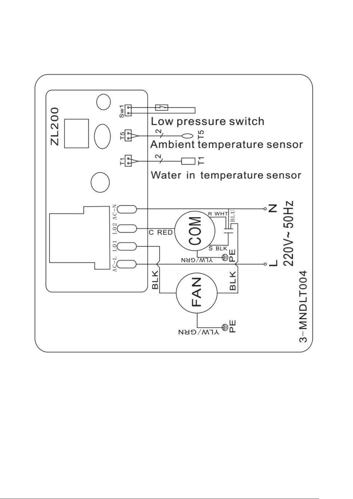
91
5. Cablaggio elettrico
5.1 Schema elettrico di una pompa di calore per piscine
Codice; HPM20
Page 95
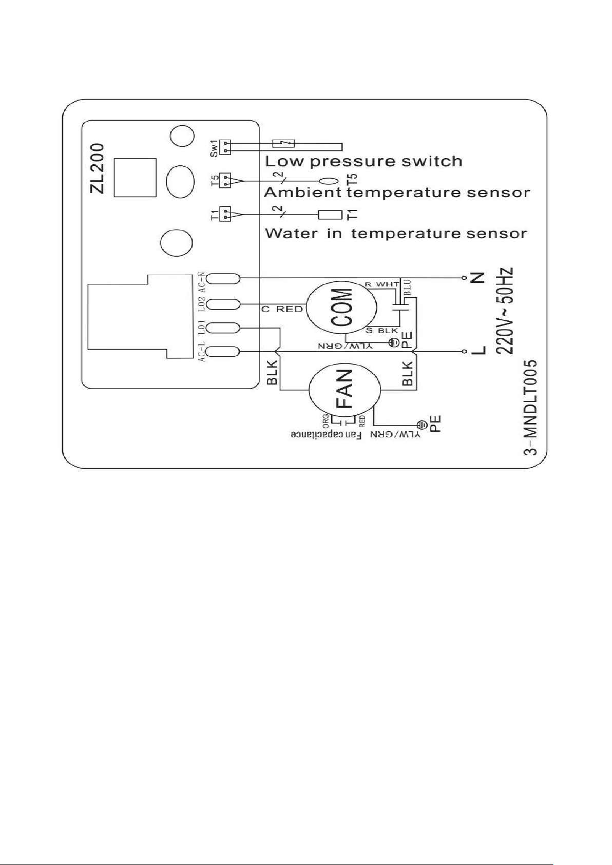
92
5.2 Schema elettrico di una pompa di calore per piscine
Codice; HPM30/HPM40
(1) Lo schema elettrico di cui sopra è solo per vostro riferimento, si prega di considerarlo in funzione
(2) La pompa di calore per piscine deve essere collegata al circuito di terra, anche se lo scambiatore dell’unità
NOTE:
dell’apparecchiatura cui si riferisce lo schema
è isolato elettricamente dal resto dell’unità. La messa a terra dell’unità è obbligo di Legge per proteggervi
da corto circuiti interni all’unità. È necessario, inoltre, fissare saldamente la pompa di calore.
Disconnessione: Un sistema di disconnessione elettrica deve essere disponibile a vista e facilmente accessibile
dall’unità (salvavita, interruttore fusibili). Si tratta di una pratica comune per pompe di calore per uso
domestico e commerciale. Evita l’inattesa accensione di apparecchiature non sorvegliate e consente di togliere
l’alimentazione mentre l’unità è sottoposta a manutenzione.
Page 96
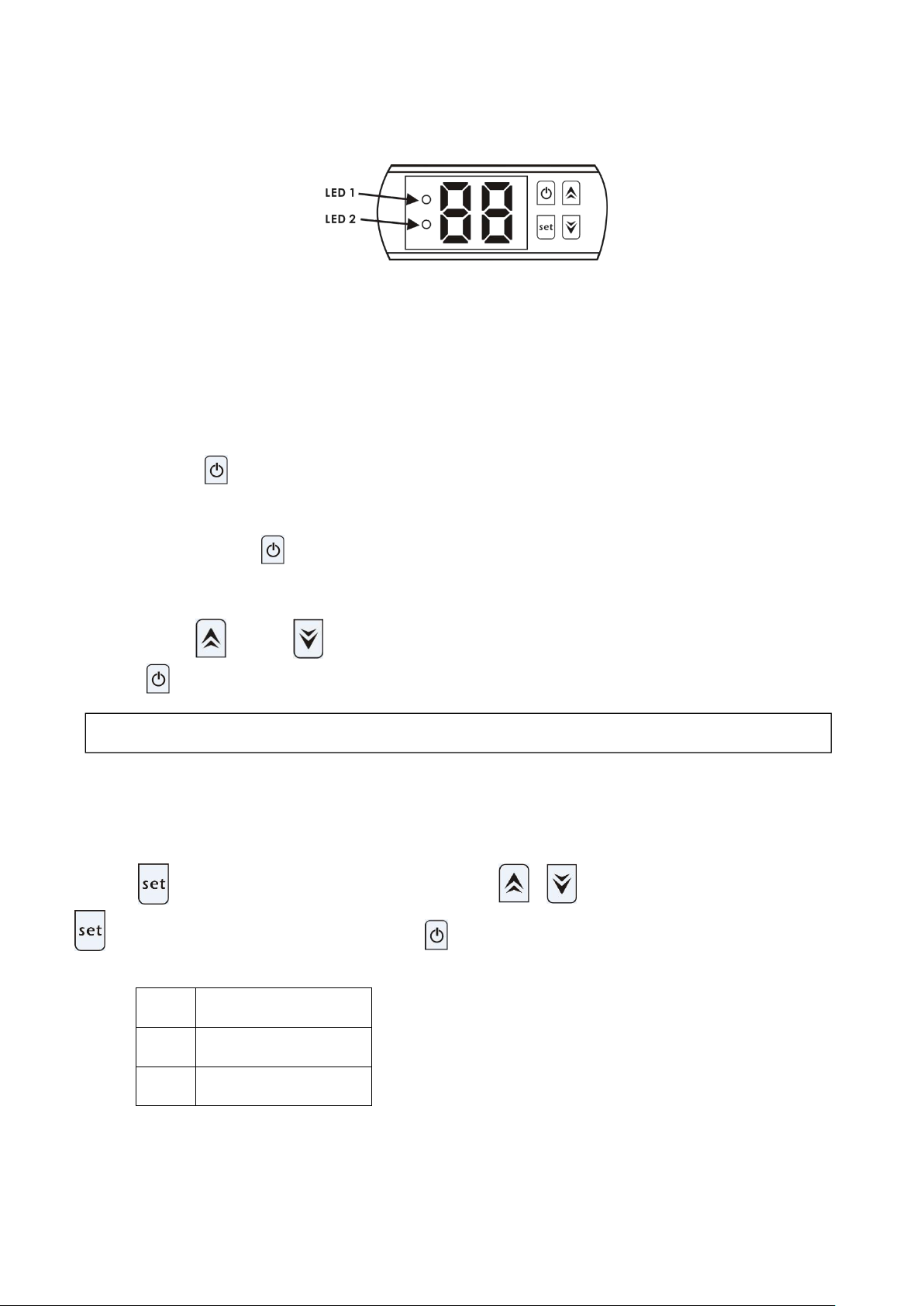
93
6. Funzionamento del controller display
6.1 I tasti del controller LED wire
Mentre la pompa è in funzionamento, il display a LED mostra la temperatura dell’acqua in entrata.
6.2 Accensione/spegnimento dellapompa di calore
6.3 Impostare la temperatura dell’acqua
Codice
Parametro
d0
Temperatura ambiente
d1
Temperatura dell’acqua
NOTA: la pompa di calore può funzionare solo se il sistema dell’acqua di filtrazione è in funzionamento.
LED 1 è acceso mentre il compressore è in funzionamento .
LED 2 è acceso se l’unità è in errore.
Premere il tasto per accendere la pompa di calore,ildisplay a LED mostra per 5 secondi la temperatura
dell’acqua impostata, poi mostra la temperatura dell’acqua in entrata.
Premere di nuovo il tasto per spegnere la pompa di calore.
Premere il tasto o il tasto per regolare il set point della temperatura dell’acqua(intervallo:.10—42°C)
Premere per salvare l’impostazione e quindi uscire.
6.4 Come controllare i parametri
Premere ,entrerà nel controllo dei parametri, Premere o scegliere il codice d0 / d1,Premere
, mostrerà il valore misurato. Infine, premere per uscire.
Avviso: I dati dei parametri non possono essere impostati dagli utenti finali.
Page 97

94
7. Risoluzione dei problemi
7.1 Codice di errore sul controller LED
Problema
Codice
Causa
Soluzione
Protezione temperatura
ambiente troppo alta o
troppo bassa
P0
1. La temperatura
ambiente è fuori
dall’intervallo operativo:
12°C- 42°C.
2. Errore del controller.
1. Attendere che la temperatura
ambiente raggiunga i 13°C o
scenda a 40°C e riavviare.
2. Sostituire il nuovo controller.
Errore della sonda di
temperatura dell’acqua
P1
Sonda di temperatura
dell’acqua circuito aperto o
corto circuito.
Sostituire la sonda di
temperatura dell’acqua
Errore della sonda di
temperatura ambiente
P2
Sonda di temperatura
ambiente circuito aperto o
corto circuito.
Sostituire la sonda di
temperatura ambiente
Protezione bassa pressione
EL
1. Interruttore di
bassa pressione non
funzionante o
disconnesso
2 Perdita di gas.
Deve essere riparato da un
tecnico specializzato
Page 98

95
7.2 Altri malfunzionamenti e soluzioni (non viene mostrato nulla sul controller LED wire)
Problema
Si Osserva
Causa
Soluzione
Pompa di
calore non
funzionante
Non viene
mostrato nulla sul
controller LED wire
Nessuna alimentazione
Verificare il cavo e l'interruttore
di circuito se collegato
Il controller LED
wire
mostra l’attuale
temperatura
dell’acqua.
1. La temperatura dell’acqua sta
raggiungendo la temperatura
impostata, pompa di calore in
modalità di temperatura
costa.
2. La pompa di calore ha appena
iniziato a funzionare.
1. Verificare l'impostazione della
temperatura dell'acqua.
2. Avvio della pompa di calore
dopo pochi minuti.
Breve
funzionamento
Il controller LED wire
mostra l’attuale
temperatura
dell’acqua e nessun
codice errore
1. Ventilatore NON funzionante.
2. La ventilazione dell’aria non è
sufficiente.
3. Il refrigerante non è
sufficiente.
1. Verificare le connessioni
dei cavi tra motore e
ventilatore, se necessario,
sostituire.
2. Verificare la posizione
dell’unità pompa di calore,
ed eliminare tutti gli ostacoli
che impediscono una buona
circolazione dell’aria.
3. Sostituire o riparare
l’unità pompa di calore.
Macchie di acqua
Ristagno d’acqua sulla
pompa di calore
1. Cementificazione.
2. Perdita d’acqua.
1.Nessuna azione.
2. Controllare lo scambiatore di
calore in titanio attentamente per
trovare eventuali difetti.
Page 99
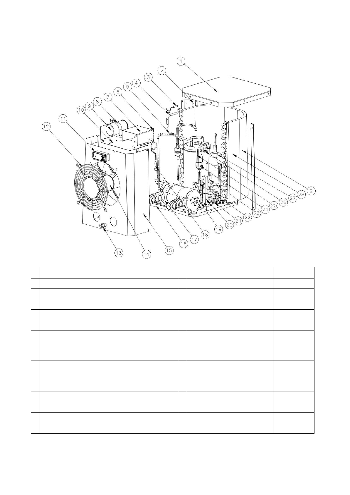
96
8. Esploso
Unità: HPM20
No
Parte di ricambio
HPM20
No
Parte di ricambio
HPM20
1
Copertura superiore
108680024
16
Base
108680029
2
Colonna
108680018
17
Scambiatore in titanio
102040699
3
Sonda temp. ambiente
117110079
18
Tubo in rame
113100026
4
Tubo in rame
113100027
19
Sonda temperatura acqua
117110068
5
Tubo esausto
113010232
20
Pannello valvola a globo
108680007
6
Capillare
109000090
21
Tubo di raccolta gas
113050123
7
Scatola elettrica
108680016
22
Valvola a globo
120000091
8
Clip capacitore del compressore
108010008
23
Tubo in rame
113100008
9
Capacitore del compressore
111000038
24
Tubo di ritorno gas
113020328
10
Placca superiore del motoventilatore
108680015
25
Interruttore di bassa pressione
116000017
11
Controller
117020165
26
Capillare valvola a globo
109000048
12
Griglia frontale
108680017
27
Compressore
101000191
13
Cavo di alimentazione
142000126
28
Evaporatore
103000236
14
Gruppo motoventilatore
112000071
29
Cavo elettrico
139000050
15
Pannello frontale
108680030
Page 100
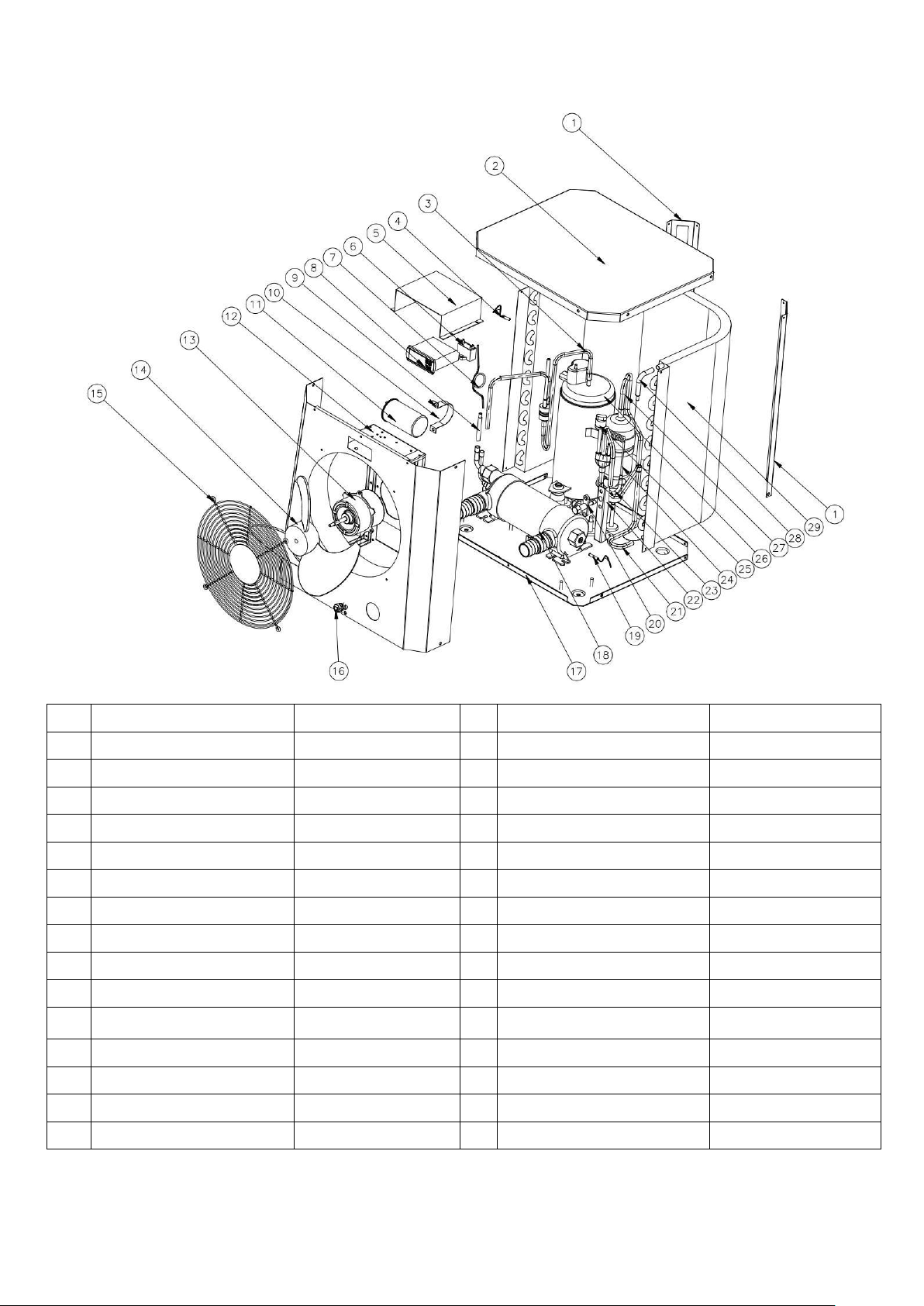
97
Unità: HPM30/HPM40
No.
Parte di ricambio
HPM30/40
No.
Parte di ricambio
HPM30/40
1
Colonna
108690009
16
Cavo di alimentazione
142000126
2
Copertura superiore
108690008
17
Base
108690020/108690022
3
Tubo esausto
113010225/113010304
18
Scambiatore in titanio
102040700/102040746
4
Sonda temp. ambiente
117110079
19
Sonda temperatura acqua
117110068
5
Scatola elettrica
108690015
20
Valvola a globo
120000091
6
Capacitore ventola
111000034
21
Tubo di raccolta gas
113050125
7
Capillare
109000038/109000012
22
Pannello valvola a globo
108680007
8
Controller
117020165
23
Tubo in rame
113100008
9
Tubo in rame
113420129
24
Capillare valvola a globo
109000048/109000043
10
Clip capacitore compressore
108010006
25
Interruttore bassa pressione
116000017
11
Capacitore compressore
111300013/111000011
26
Compressore
101000183/101000210
12
Gruppo pannello frontale
108690021
27
Tubatura ritorno gas
113020316/113020412
13
Motoventilatore
112000054/112000079
28
Tubo in rame
113100027
14
Pala ventola
132000024
29
Evaporatore
103000237
15
Griglia frontale
108690005
30
Cavo elettrico
139000050
 Loading...