

Page 1
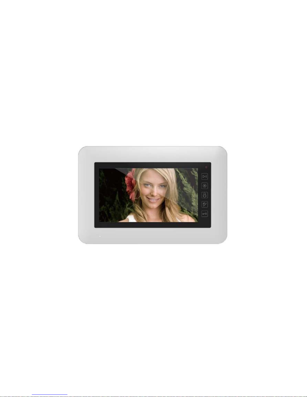
USER MANUAL
7” Touch Screen
Video Door Phone
Page 2

Table of Contents
1. Name and Functions of Each Part...................................................................................2
1.1 Front Part....................................................................................................................2
1.2 Rear Part.....................................................................................................................3
2. Features and Functions......................................................................................................4
2.1 Features......................................................................................................................4
2.2 Main Functions .........................................................................................................4
3. Packing Contents.................................................................................................................5
4. Connection Diagram............................................................................................................6
4.1 System Layout..........................................................................................................6
4.2 Wiring Diagram.........................................................................................................7
5. Installation..............................................................................................................................9
5.1 Installation location.................................................................................................9
5.2 Wire & Monitor Installation....................................................................................9
6. Operation Description.......................................................................................................10
6.1 Main Screen.............................................................................................................10
6.2 Visitor Call................................................................................................................11
6.3 Monitor Function....................................................................................................13
6.4 Multimedia................................................................................................................13
6.4.1. Image & Video Storage.....................................................................................13
6.4.2. Image & Video Review ......................................................................................13
6.4.3.
Voicemail Function ............................................................................................14
6.4.4. Photo Frame Function ......................................................................................16
6.5 Intercom Function..................................................................................................16
6.6 Telephone.................................................................................................................17
6.6.1. Call Forwarding Function.................................................................................18
6.6.2. Control the Door Station by Telephone........................................................19
6.7 Setting page.............................................................................................................19
7. Specifications......................................................................................................................24
Appendix I: Converting image for photo frame..................................................................25
Page 3
1
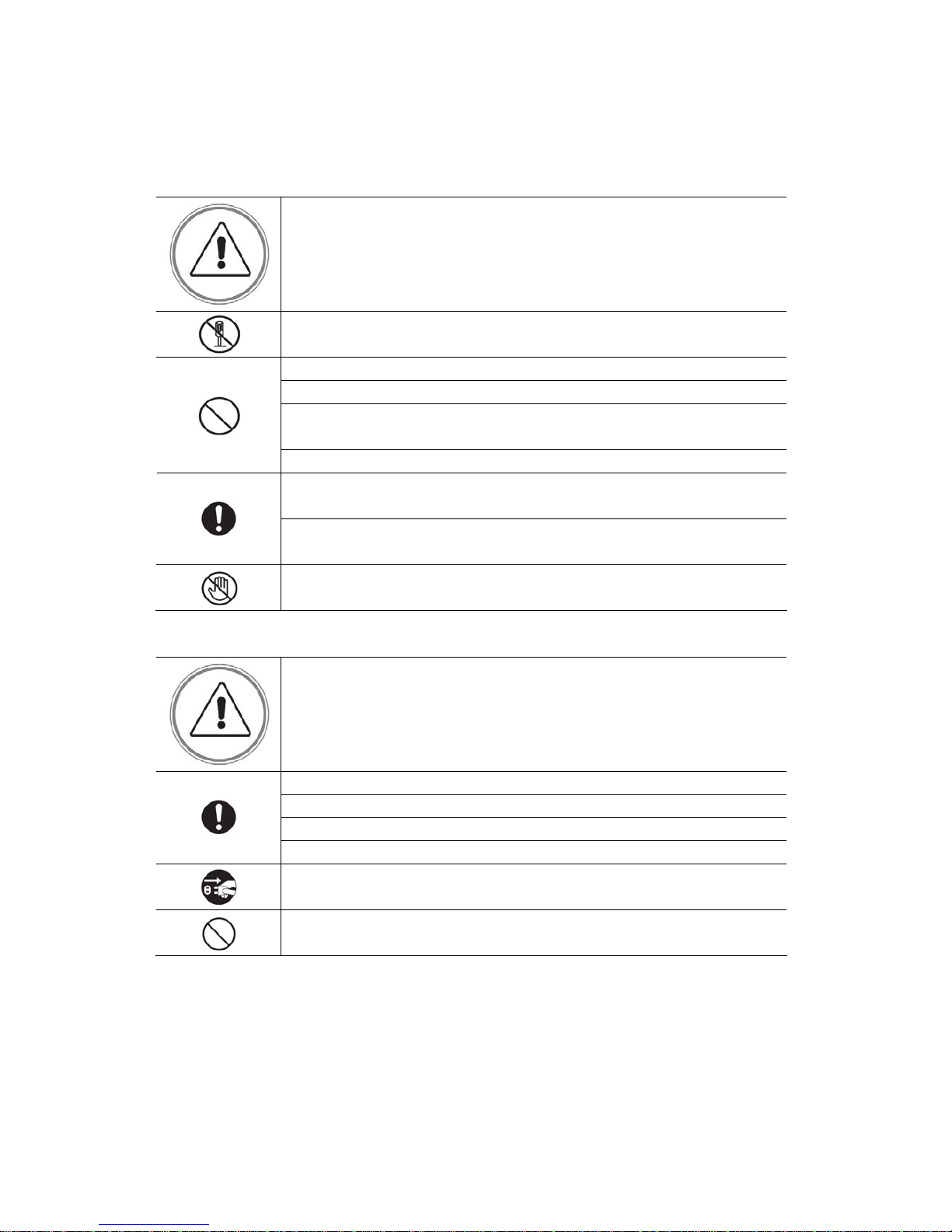
W ARNING AND CAUTION
Please make sure to follow the instructions to prevent any danger or property losses
Warning: Death or serious injury are expected
Do not disassemble, install, or repair this product on your own accord
Do not place the product near a hot or humid place
Do not forcibly bend the cord or put a heavy object on the product
Do not use water, thinner or a detergent used to wash oil products when you
wash the exterior
Do not connect to other products while in use
Make sure to clean it by using a dry cloth to prevent any breakdown or
electric shock
If the product emits a peculiar noise, odor or smoke, immediately cut off the
power, and then contact the service center
Do not put the plug in the socket with a wet hand
Caution: An injury or property losses are expected
Make sure that dust or foreign substances are not gathered on the product
Make sure to prevent foreign substances from entering the product
Avoid direct rays of the sun or heating devices at a time of installation
Install the product in a flat and stable place
Pull the plug if the product is not used for a long time
Do not unplug the TF card when recording, this generally will cause loss of
data
Page 4
2
1. Name and Functions of Each Part
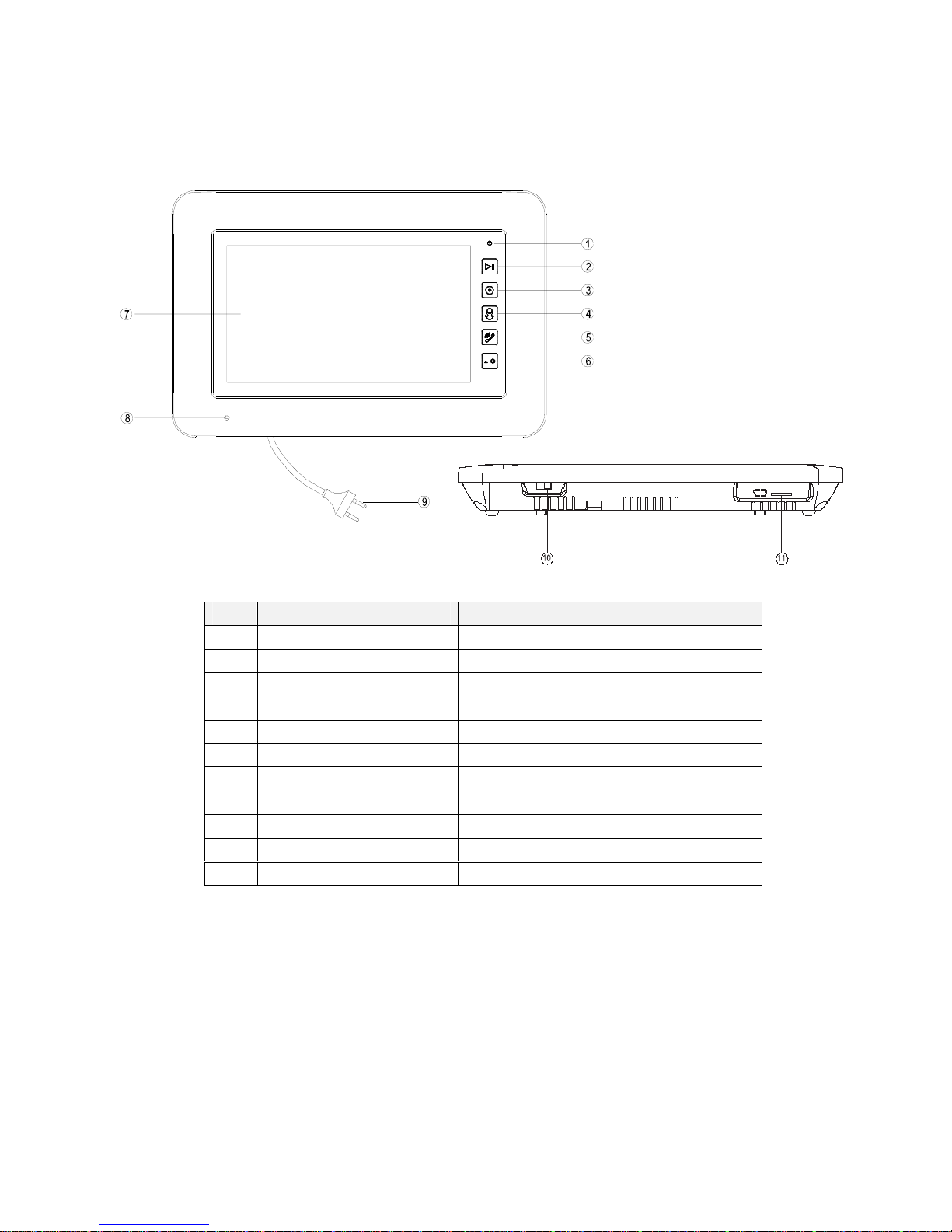
1.1 Front Part
NO. Part Name Description
1
Power Indicator
2
Review Button Touch button for reviewing picture or video
3
Intercom Button Touch button for intercom
4
Monitor Button Touch button for monitoring
5
Talk Button Touch button for talking with visitor
6
Door Release Button Touch button for releasing door
7
Touch Screen 7 inch touch screen
8
MIC Microphone
9
Power Cable AC power cable
10
Power Switch
11
TF Card Slot Socket for TF card
Page 5
3
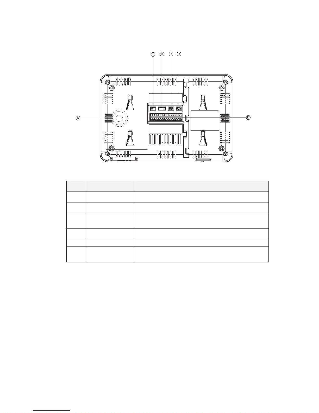
1.2 Rear Part
NO. Part name Function
12
Speaker Loud speaker
13
75Ω Switcher
Impedance matching for video signal
14
Video Input /Output
CCTV1 / CCTV2 / CCTV3 / CCTV4 / video out (2 wire in
polarity)
15
DC Power 14.5V DC supply
16
Telephone Interface for the telephone line
17
Connection
Interface
Interface for door station 1/door station 2 /extensions /audio
phone
Page 6

4
2. Features and Functions
2.1 Features
7” TFT-touch screen, 800*480 Resolution
Support 2 door stations, 4 CCTV cameras, 1 master monitor + 3 extension monitors,
1 audio phone and 1 CCTV output
Built-in flash memory:100 pictures
Support telephone function and call forwarding
TF card: 1024 images and 128 videos
16 melodies for different door stations
Support motion detection
Leaving voice messages to family & visitors
Point-to-point intercom and broadcast
Support digital photo frame
2.2 Main Functions
Monitoring and talking with a visitor
Door lock release
Support AC/DC power input
Support multi-language
Do-not-disturb function
Date and time display
Surface mount
Page 7
5
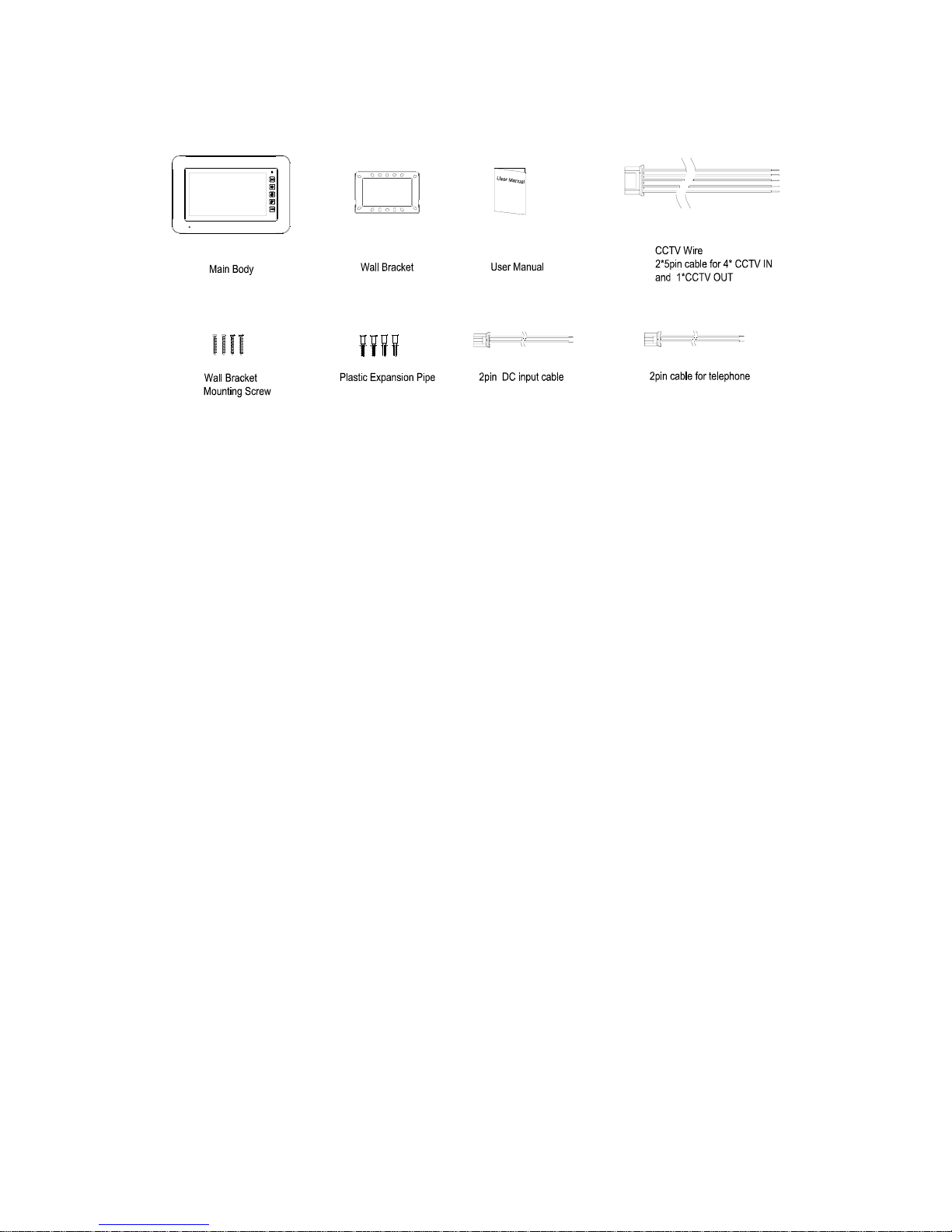
3. Packing Contents
Page 8
6
4. Connection Diagram
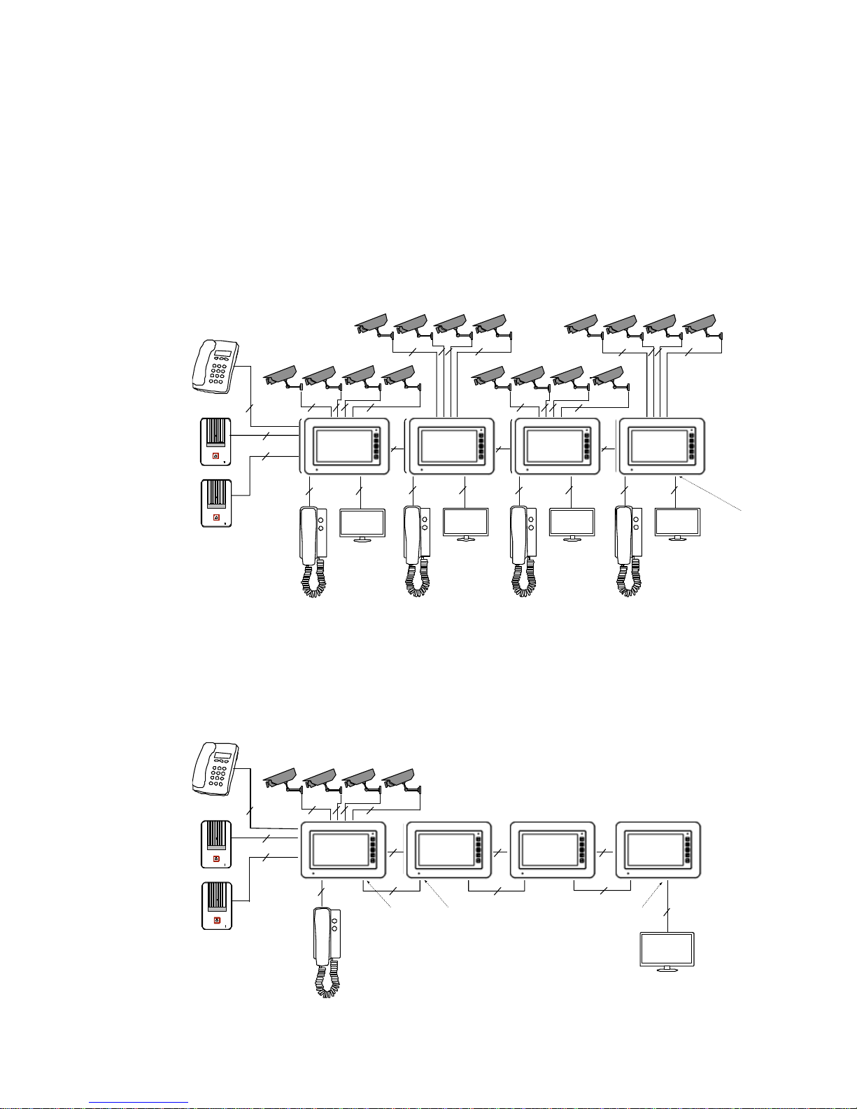
4.1 System Layout
There are two CCTV connection modes.
CCTV connection mode 1
Each monitor can connect to different CCTV, and can only monitor the directly
connected CCTV (Extensions ≤ 3).
2
4
2
4 24
2
4
2 2 2
2
2
2 2 2
2 2 2 2
2 2 2 2
4 4 4
CCTV_OUT
4
4
2
Master
Ext1 Ext2
Ext3
CCTV connection mode 2
Only master monitor can connect to CCTV, extensions get CCTV video from the master.
The extensions monitor CCTV by sending requests to the master. Only one monitor can
monitor CCTV at a time.
4
4
2 2
2
2
4 4 4
2 2 2
CCTV_OUT
CCTV_IN
4
2
Master
Ext1
Ext2
Ext3
2
CCTV_OUT
Master Ext.3 Ext.2 Ext.1
Master
Ext.1 Ext.2
Ext.3
Page 9
7
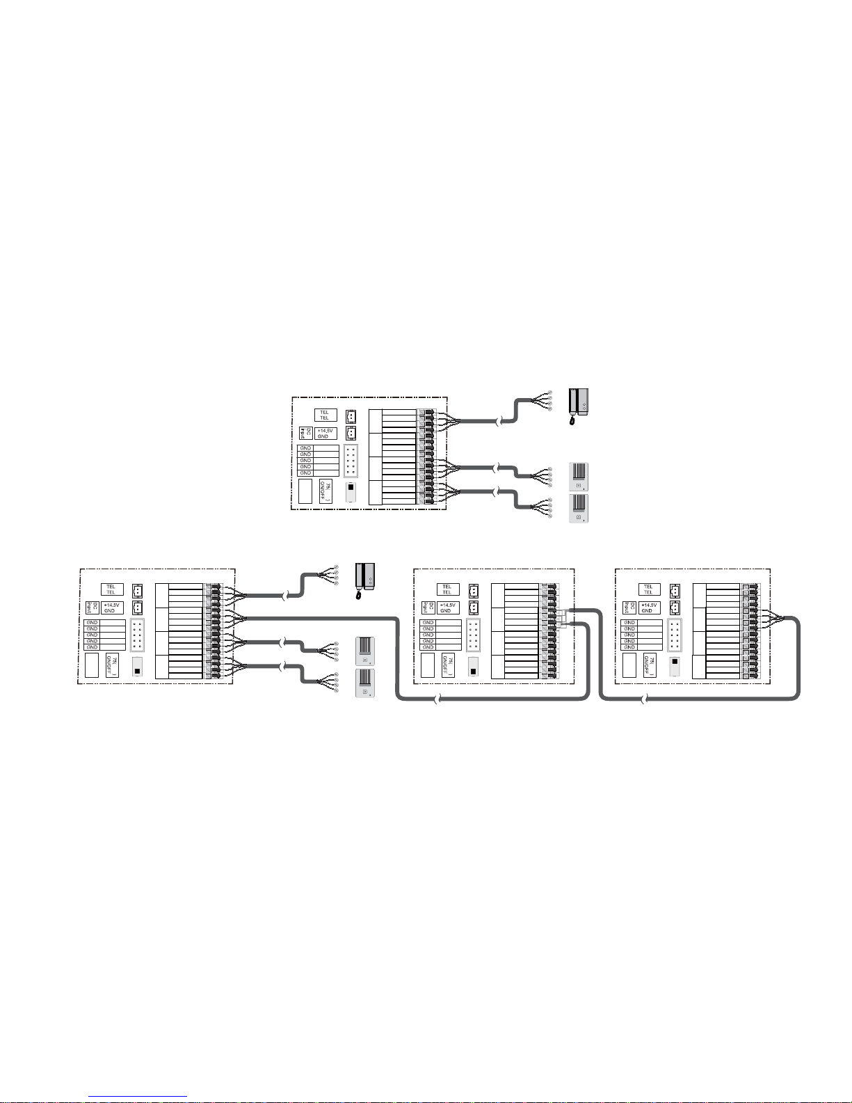
4.2 Wiring Diagram
Please be careful to wiring on polarity.
Intercom wiring diagram with one monitor
intercom
inter power
audio
phone
door 1door 2extension
inter audio
video I/O
ohm
impedance
matching
audio I/O
audio 2
audio 1
data I/O
video 2
video 1
VCC 2
VCC 1
GND
GND
GND
GND
video out
CCTV 4
CCTV 3
CCTV 2
CCTV 1
1
2
Intercom
VCC
GND
Audio
Video
VCC
GND
Audio
Video
VCC
GND
Audio
Intercom wiring diagram with master monitor and extensions (pay attention to the impedance matching switch)
intercom
inter power
audio
phone
door 1door 2extension
inter audio
video I/O
ohm
impedance
matching
audio I/O
audio 2
audio 1
data I/O
video 2
video 1
VCC 2
VCC 1
GND
GND
GND
GND
video out
CCTV 4
CCTV 3
CCTV 2
CCTV 1
intercom
inter power
audio
phone
door 1door 2extension
inter audio
video I/O
ohm
impedance
matching
audio I/O
audio 2
audio 1
data I/O
video 2
video 1
VCC 2
VCC 1
GND
GND
GND
GND
video out
CCTV 4
CCTV 3
CCTV 2
CCTV 1
intercom
inter power
audio
phone
door 1door 2extension
inter audio
video I/O
ohm
impedance
matching
audio I/O
audio 2
audio 1
data I/O
video 2
video 1
VCC 2
VCC 1
GND
GND
GND
GND
video out
CCTV 4
CCTV 3
CCTV 2
CCTV 1
(Master monitor) (Extension 1) (Extension N N≤3)
...
Intercom
VCC
GND
Audio
Video
VCC
GND
Audio
Video
VCC
GND
Audio
1
2
1
2
1
2
Page 10
8
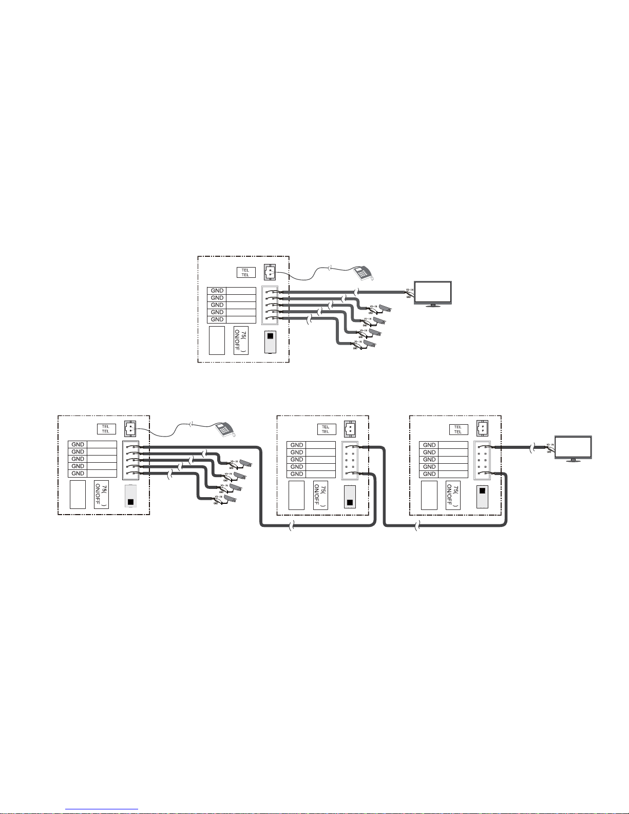
CCTV connection mode 1
Each monitor can connect to different CCTV, can and can only monitor the connected CCTV.
ohm
impedance
matching
video out
CCTV 4
CCTV 3
CCTV 2
CCTV 1
1
2
CCTV connection mode 2
Only the master can connect to CCTV, extensions get CCTV video from the master. The extensions monitor CCTV by sending requests to the master.
Only one monitor can monitor CCTV at a time (pay attention to the impedance matching switch).
...
(Extension N N≤3)(Extension 1)(Master monitor)
ohm
impedance
matching
video out
CCTV 4
CCTV 3
CCTV 2
CCTV 1
ohm
impedance
matching
video out
CCTV 4
CCTV 3
CCTV 2
CCTV 1
ohm
impedance
matching
video out
CCTV 4
CCTV 3
CCTV 2
CCTV 1
1
2
1
2
1
2
Page 11
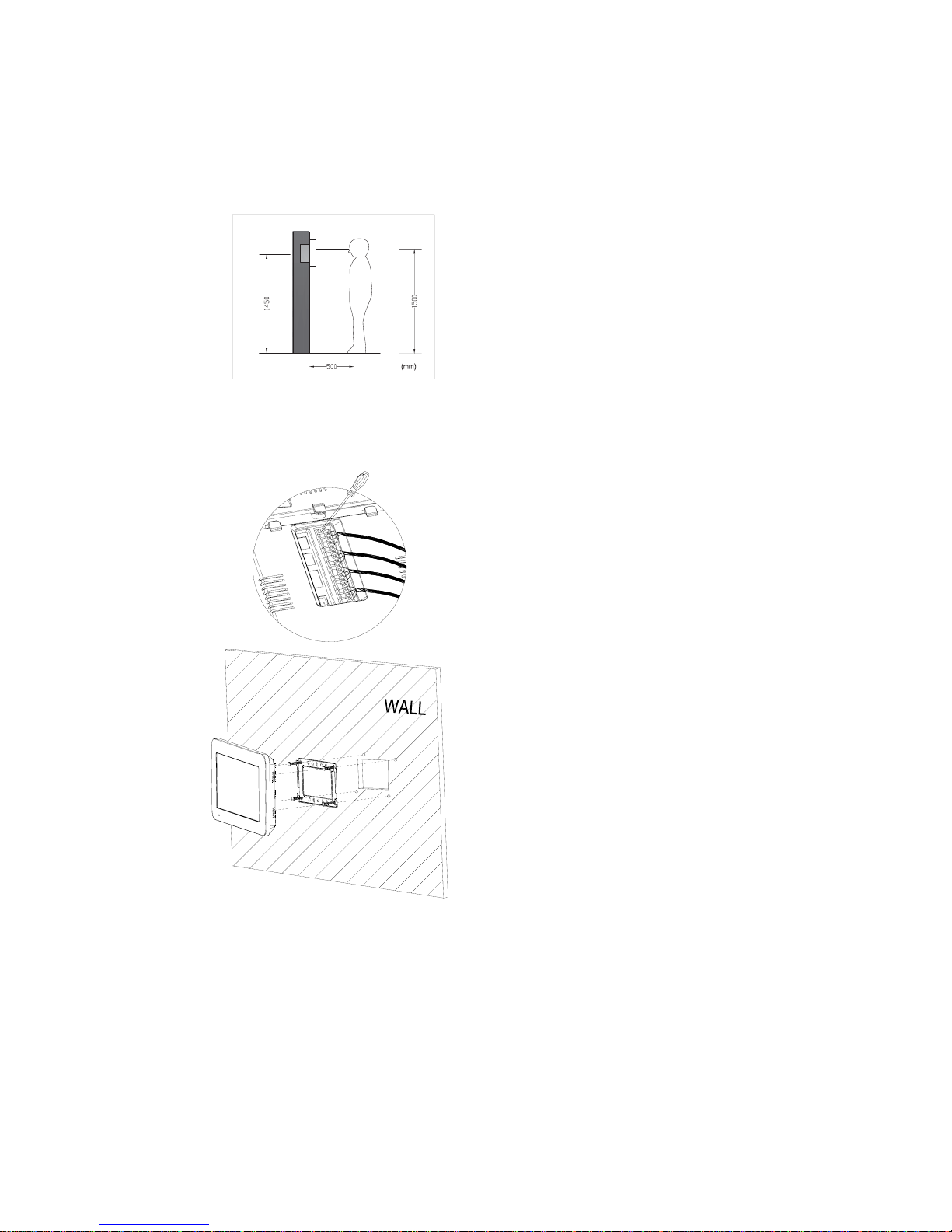
9
5. Installation
5.1 Installation location
Monitor installation location
Standard monitor installation height is about
1,500mm where screen center is at eye level; in
this case, wall-hanging metal center is 1,450mm
above ground level.
5.2 Wire & Monitor Installation
1) Push down the button with screwdriver
2) Put the wire into the hole from the bottom
3) Release the screwdriver
4) Check the fastness of the wire
5) Remove wall-hanger bracket behind monitor
6) Install wall-hanger bracket
7) Connect wires to back terminal of monitor,
referring to connection diagram
8) Hang monitor on wall-hanging, and fix
monitor on wall-hanger bracket
9) Plug monitor’s power plug into power socket
Page 12
10
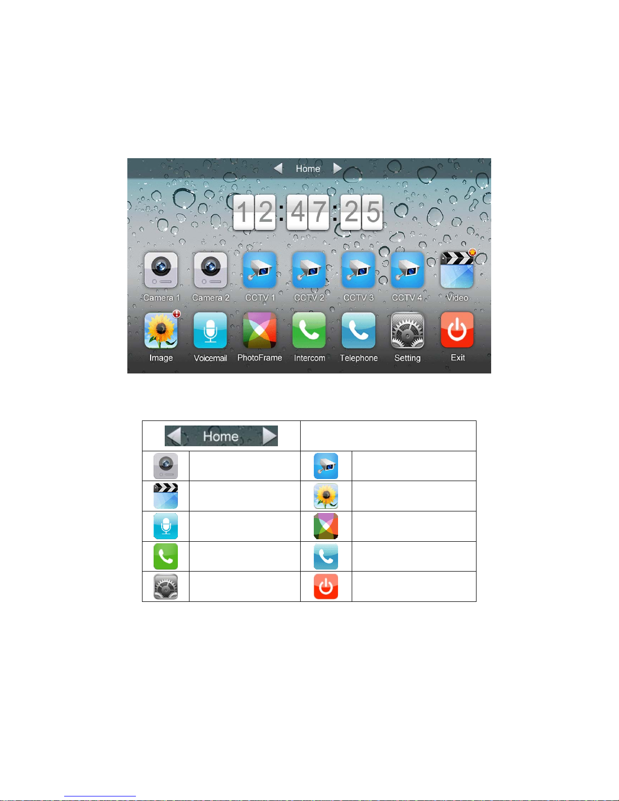
6. Operation Description
6.1 Main Screen
It will show corresponding functions when pressing each icon on main screen.
Icon Definition:
Home/Leaving/Do Not Disturb
enter [Camera]
enter [CCTV] page
enter [Video] page
enter [Image] page
enter [Voicemail] page
enter [Photo Frame] page
enter [Intercom] page
enter [Telephone] page
enter [Setting] page
turn off screen
In [Leaving] mode, when door station calls in, the monitor will play the voicemail to
visitor, if the voice message is recorded and been set in the [Setting] page. In [Do not
Disturb] mode, when door station calls in, the monitor will be mute.
Remark: To set the voicemail, please see 6.7
Page 13
11
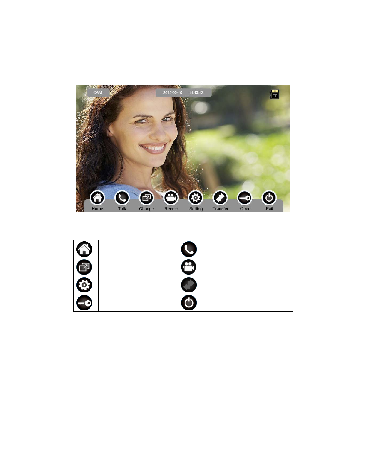
6.2 Visitor Call
When door station calls in, the visitor’s image will be shown on the monitor screen
(on-screen duration 90 seconds).
Icon Definition:
back to [Main Screen]
talk
switch between door stations
and CCTVs
record video
adjust display parameters
call transfer manually
open the door
turn off screen
When a door station calls in, press [Talk] to start to talk; press [Talk] again to terminate
the talk.
Page 14
12
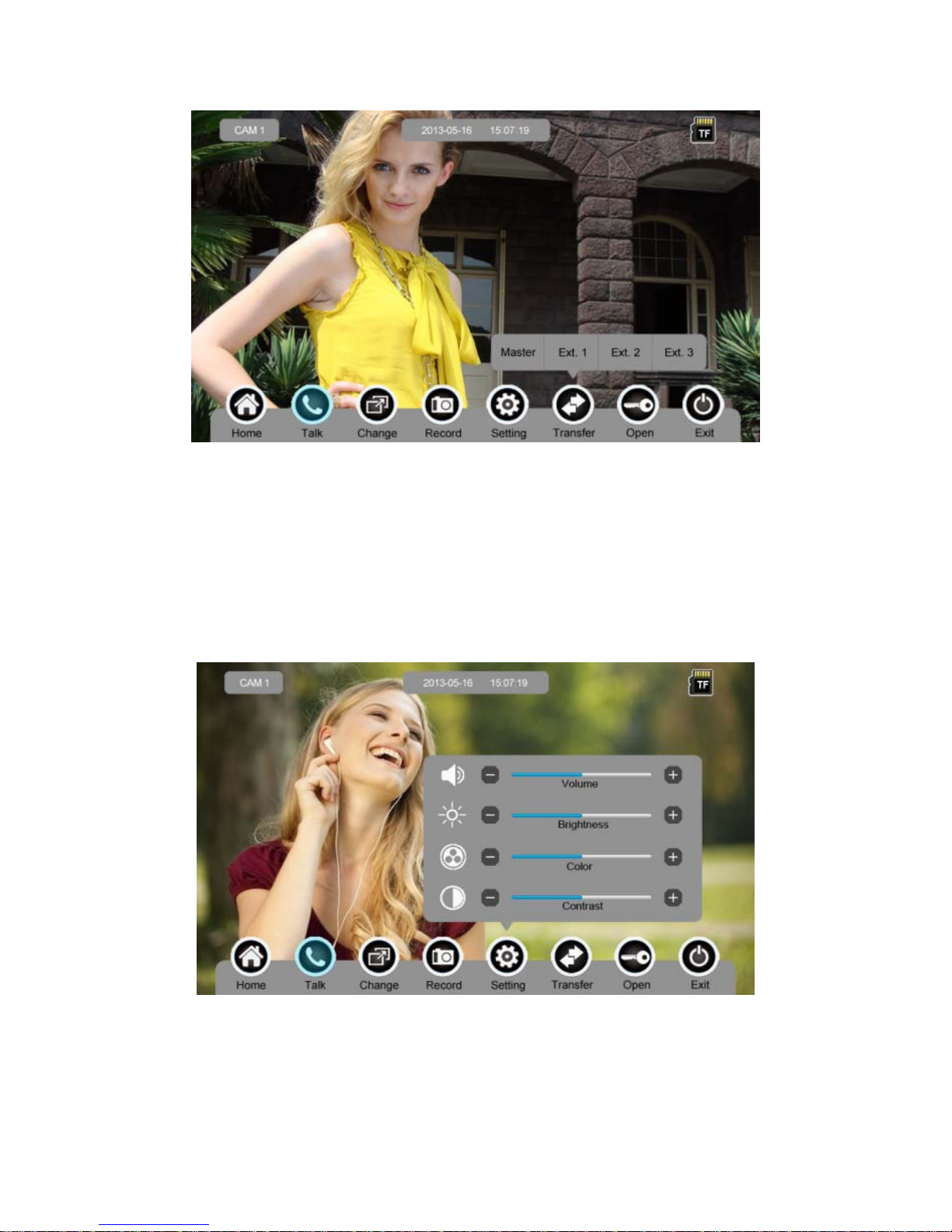
During the talk:
¾ press [Change] to switch to other door station or CCTV, and the current talk will
be terminated.
¾ press [Record] to record a video clip or capture a picture from the calling door
station, depending on the system setting (see 6.7).
¾ press [Setting] to adjust the sound volume, brightness, color and contrast.
¾ press [Transfer] to transfer the current call to other extension monitors.
¾ press [Open] to release door.
¾ press [Exit] or [Home] to end the talk.
Page 15
13
6.3 Monitor Function
When you press the [Camera1]/[Camera2] or [CCTV1]/[CCTV2]/[CCTV3]/[CCTV4]
icon on main screen, the system will enter monitor mode, and will show image from the
corresponding door station/CCTV.
Remark: The [Transfer] buttons will be in disable status under monitor mode.
6.4 Multimedia
6.4.1. Image & Video Storage
If you insert TF card, monitor can record image and video, if you do not insert TF card,
monitor can only record image.
Maximum Capacity: TF card: 1024 images and 128 videos
Built-in flash memory: 100 images
When full, the newest image/video will automatically overwrite the oldest image/video.
6.4.2. Image & Video Review
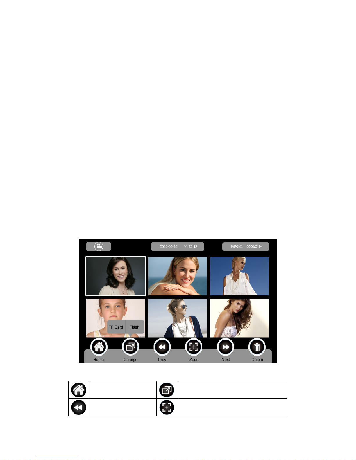
Press [Image] or [Video] on main screen, you can review the image/video. There are 6
Images/Videos in one page. The image/video with white borderlines means that the
image is selected.
Icon Definition:
return to [Main Screen]
switch between TF card and flash memory
show previous page zoom in/out image and video
Page 16
14
show next page delete the selected image/video
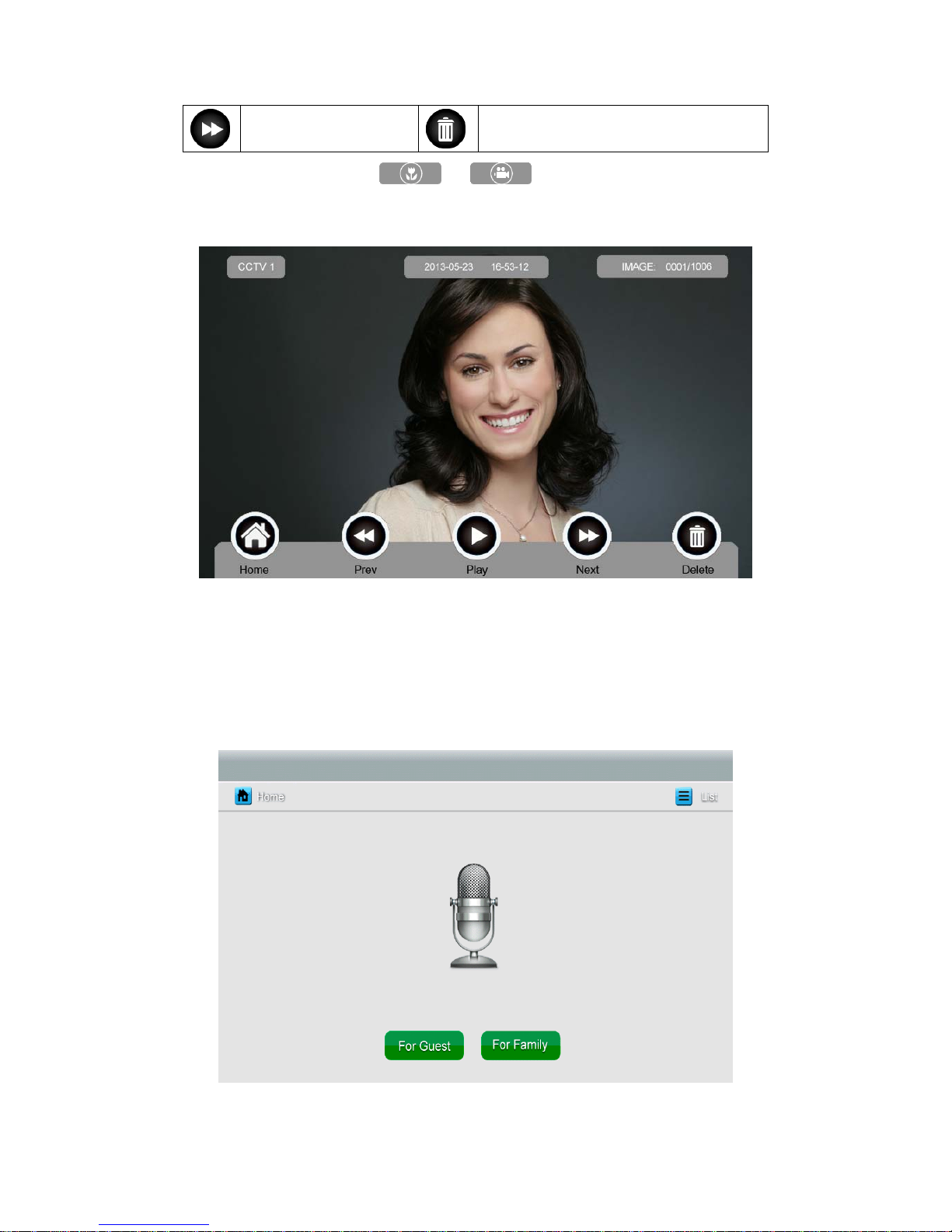
You can press the icon or on the top left corner to switch
[Image]/[Video] review mode.
6.4.3. Voicemail Function
Audio Message Record
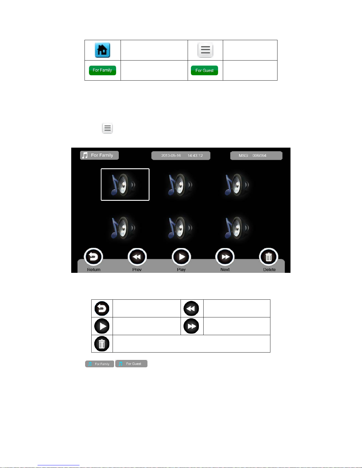
Press [
Voicemail] on main screen to record an audio message.
Icon Definition:
Page 17
15
return to [Main Screen]
List: view audio
message
leave a voice message
for family
leave a voice
message for guest
Press [For Guest] / [For Family], enter the recording page to record voice message.
Monitor support up to 30s for each message.
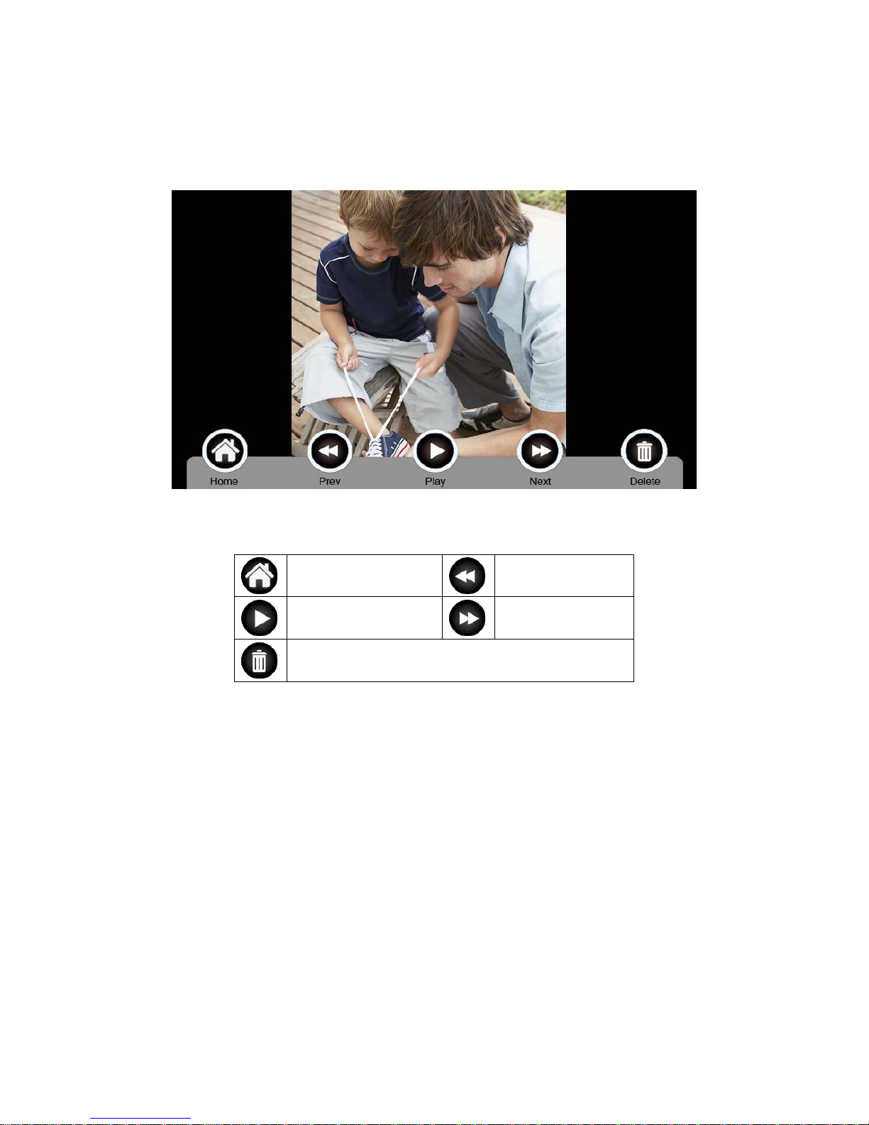
Review Audio Record
Press
to review records.
Icon Definition:
return to [Main Screen]
play previous clip
play
play next clip
delete
/ : Switch between family message list and guest message
list.
Remarks:
Up to 32 messages for family and 2 messages for guest. When full, the
newest message will automatically overwrite the oldest message
This function can be supported with TF card only.
Page 18
16
6.4.4. Photo Frame Function
Press [Photo Frame] on main screen, monitor will play the image one by one
automatically.
Icon Definition:
return to [Main Screen]
show previous image
display image show next image
delete
Remark: Only photos with specific format can be shown in the photo frame.
To convert the photo, please see Appendix I.
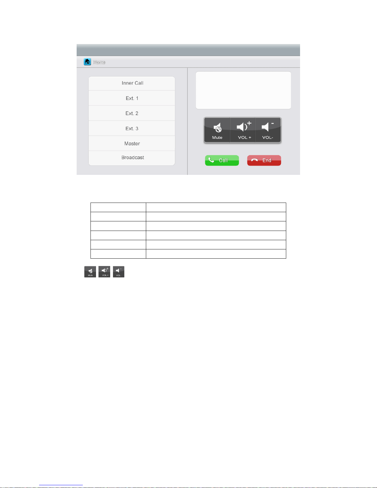
6.5 Intercom Function
Press the [Intercom] icon on main screen, choose the monitor you want to call, and
then press [Call], and then you can talk with the corresponding monitor.
Page 19
17
Icon Definition:
[Inner Call]
call the audio phone
[Ext. 1]
call extension monitor 1
[Ext. 2]
call extension monitor 2
[Ext. 3]
call extension monitor 3
[Master]
call master monitor
[Broadcast]
call all monitors
: In the [Intercom] page, you can enable/disable [Mute] function, and
adjust the volume.
To set intercom address: please see [Setting] Æ [Intercom].
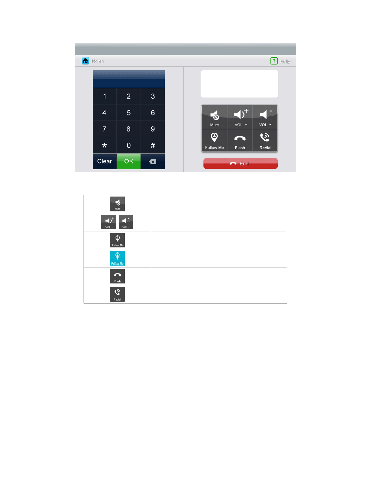
6.6 Telephone
The Monitor can support telephone function:
Make and receive a telephone call
Transfer the call from door station to a specific mobile phone or fixed phone and
control the door station via telephone.
Page 20
18
Icon Definition:
enable/disable [Mute] function
adjust volume
enable/disable call forwarding function
[Call Forwarding] function is enable
reset phone
redial
6.6.1. Call Forwarding Function
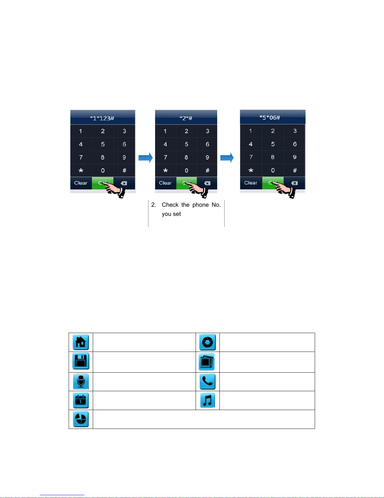
To use call forwarding function, you need set a forwarding telephone number, please
take the following steps:
1. Press [Telephone] icon on main screen, enter [Telephone] page
2. Set a telephone number you want to forward:
*1* Æ Phone Number Æ # Æ OK
Remark: The tel. number should be within 20 numbers.
3. Check the telephone number:
*2* Æ # ÆOK
Page 21
19
4. Set ring time before call forwarding,
*5* Æ Ring Time Æ # Æ OK
Remark: The ring time range = [1s ~ 30s], and you must input 2 figures.
For example:
1. Set "
123" as forwarding
phone number
2. Check the phone No.
you set
3. Set the waiting time: "0
6s"
6.6.2. Control the Door Station by Telephone
When no one answers the call from door station, the call will be transferred to your
telephone. During the talk, input 2 + ‘#’ to open the door.
6.7 Setting page
Press [Setting] icon to set up the system.
Icon Definition:
return to [Main Screen]
enter [Camera] setting page
enter [Monitor Record] setting page
enter [Photo Frame] setting page
enter [Voicemail] setting page
enter [Intercom] setting page
enter [General] setting page
enter [Melody] setting page
restore factory setting
Remarks: The [Photo Frame] setting is not available in this version.
Page 22
20
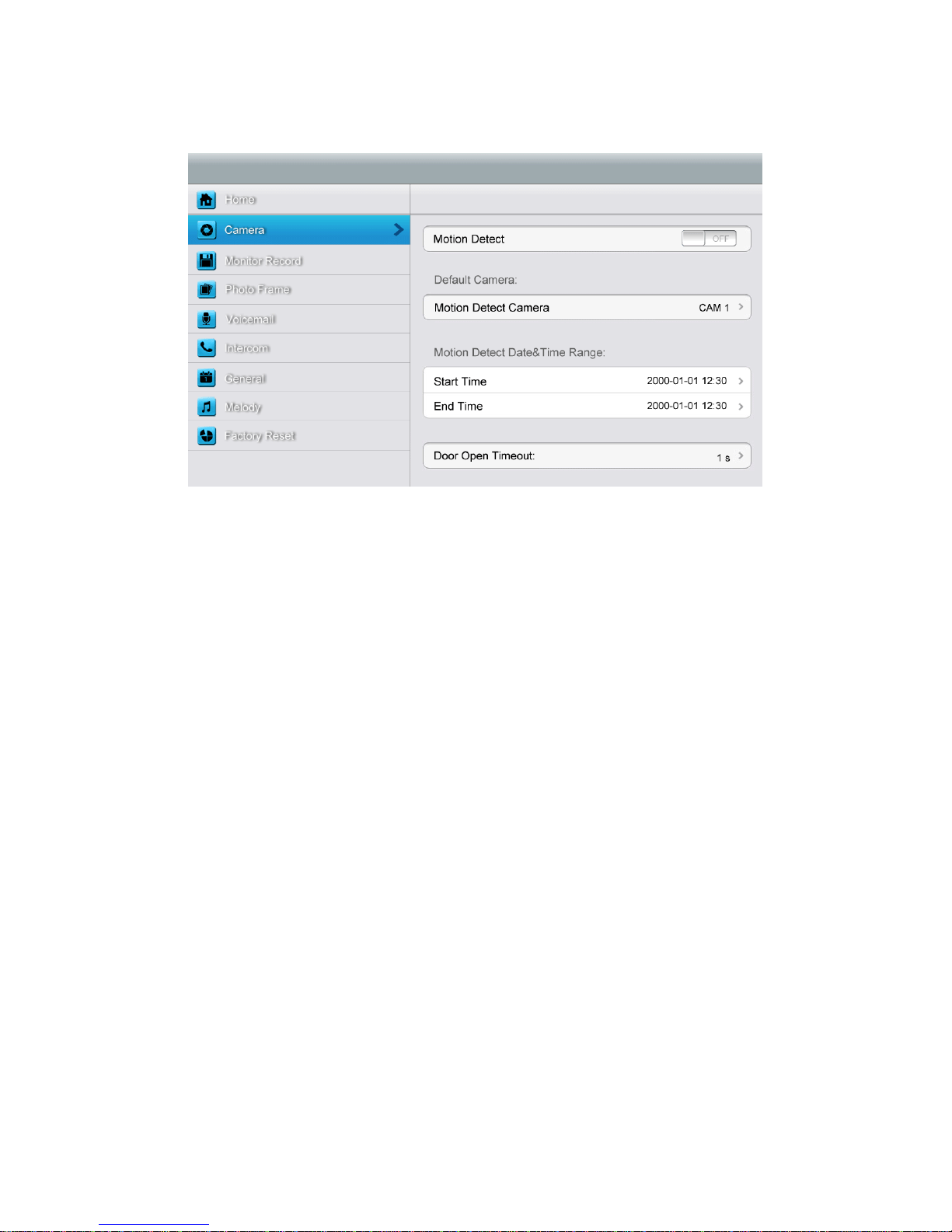
[Camera] setting page
In this page, you can turn [Motion Detect] on or off, set one camera as default for
monitoring, set default camera for motion detection, set detection start & end time and
set door open timeout.
¾ To set a default camera for motion detection, enter into option list:
CAM1/CAM2/CCTV1/CCTV2/CCTV3/CCTV4
Choose one option → Press [Return] button.
¾ To set time range for motion detection, you can set the start time and the end time.
¾ To set door open timeout, enter into option list:
1 s/2 s/3 s/Open While Pressing
Choose one option 错误!未找到引用源。 Press [Return] button.
Remark: Once a moving object is detected, camera will automatically capture a video of
15s. When monitoring door station or CCTV, motion detection will pause until the
monitoring ends.
Page 23
21
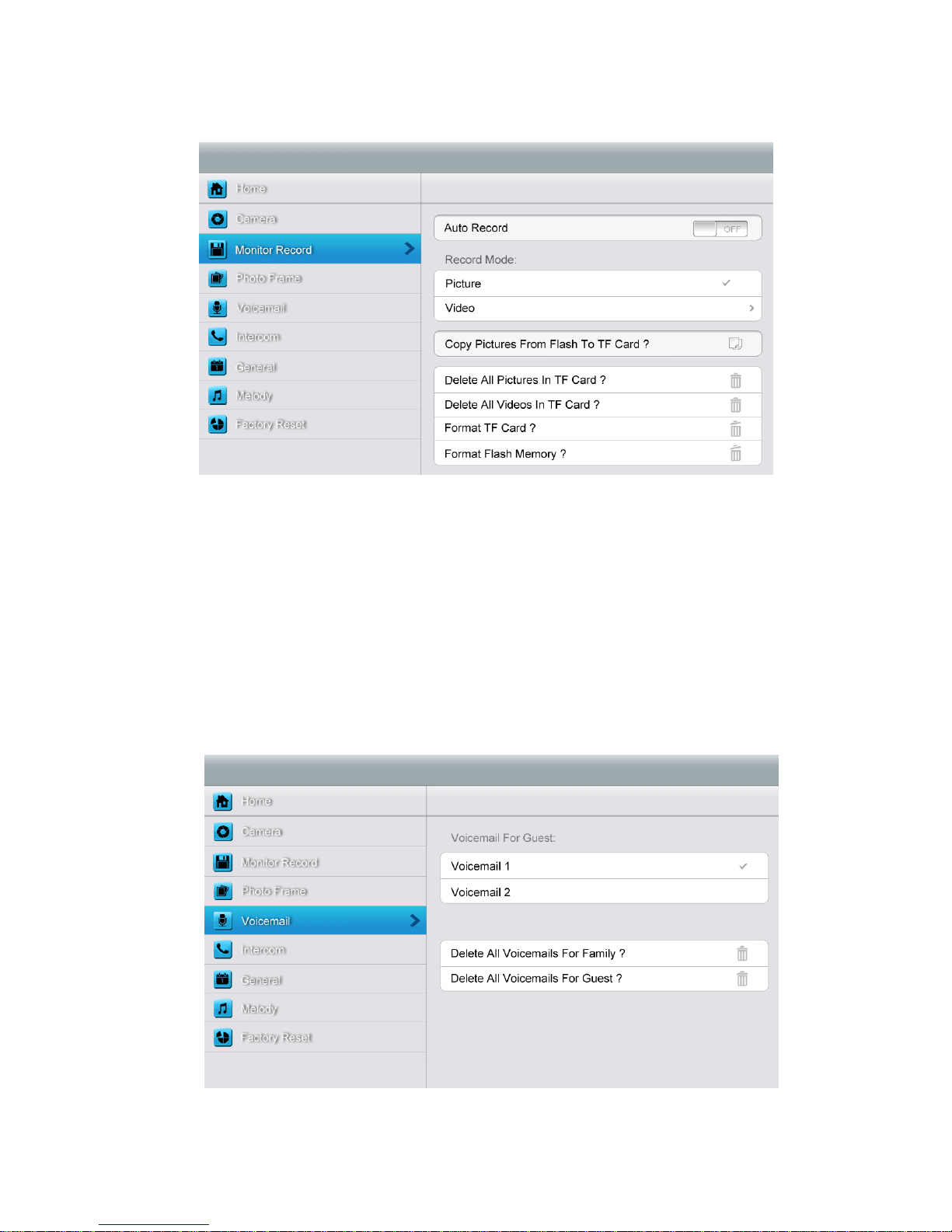
[Monitor Record] setting page
In this page, you can
¾ Turn [Auto Record] on or off. If [Auto Record] is on, the monitor will capture
pictures or videos automatically, when door station calls in.
¾ Select picture or video record mode. To set video recording timeout, enter into
drop-down option list: 15 s/30 s/60 s.
¾ Copy/delete pictures and videos.
¾ Format TF card and flash memory.
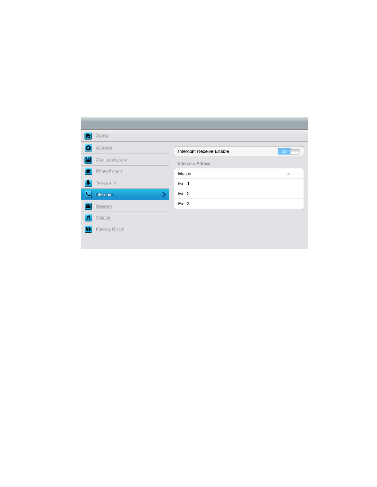
[Voicemail] setting page
Page 24
22
In this page, you can select one voicemail for guest as the message to play under
[Leaving] mode.
Remark: The Voicemail message is stored on the TF card. This configuration will be
invalid if there is no valid TF card inserted. To record message for guest, please see
6.4.3.
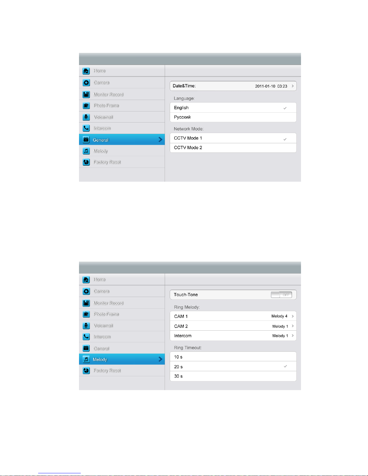
[Intercom] setting page
In this page, you can
¾ Turn [Intercom Receive Enable] on or off.
¾ Set up intercom address. Main monitor should be set up as “Master”, extension
monitors should be set up as “Ext.1”,”Ext.2”,”Ext.3” successively.
Page 25
23
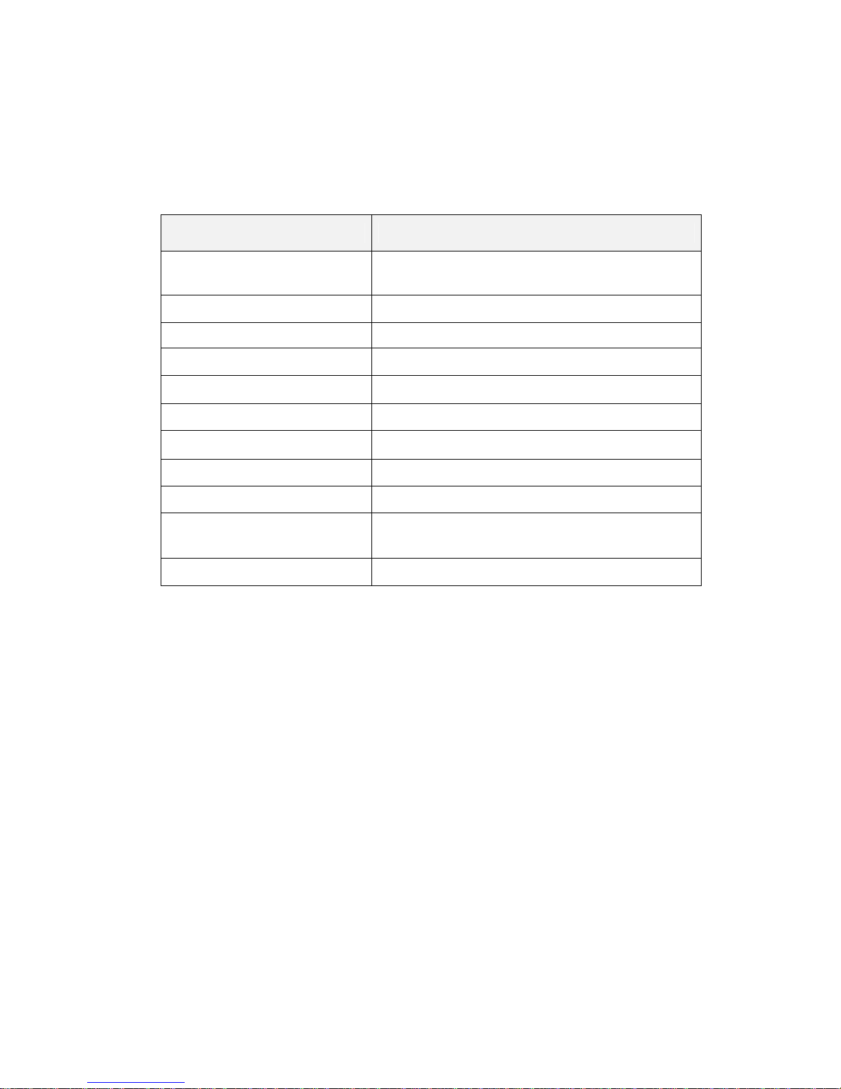
[General] setting page
In this page, you can set up date & time; select a language and CCTV mode. Default
option - CCTV mode 1.
Remark: The CCTV mode of every monitor should keep the same. With the CCTV
mode of master monitor changing, the extensions’ CCTV mode will change
automatically. Note that you should set the master and extension properly.
[Melody] setting page
In this page you can:
¾ Turn [Touch Tone] on or off.
¾ Select ring melody for door station 1, door station 2 and intercom.16 melodies for you
to choose.
Page 26
24
¾ Set ring timeout:10 s/20 s/30 s.
In [Factory Reset] setting page you can restore system to factory settings (except date
& time, intercom address).
7. Specifications
Category Specification
Input power
AC: 100V ~ 240V, 50Hz/60Hz
DC: 14.5V
Power Consumption Max: 12W, standby: 5W
TFT LCD 7 inch digital TFT LCD
LCD resolution 800(RGB) x 480
Connection with door station Support two 4-wire door stations
Connection with CCTV Support four 2-wire CCTV input
Connection with extension monitor Support three extension monitors
Connection with audio phone Support one 4-wire audio phone
Connection with video out Support one 2-wire video out
Memory capacity
TF card: 1024 pictures, 128 videos
Flash: 100 pictures
Dimensions (mm) 238mm (W) * 157mm(H) * 28.5mm(D)
Page 27
25
Appendix I: Converting image for photo frame
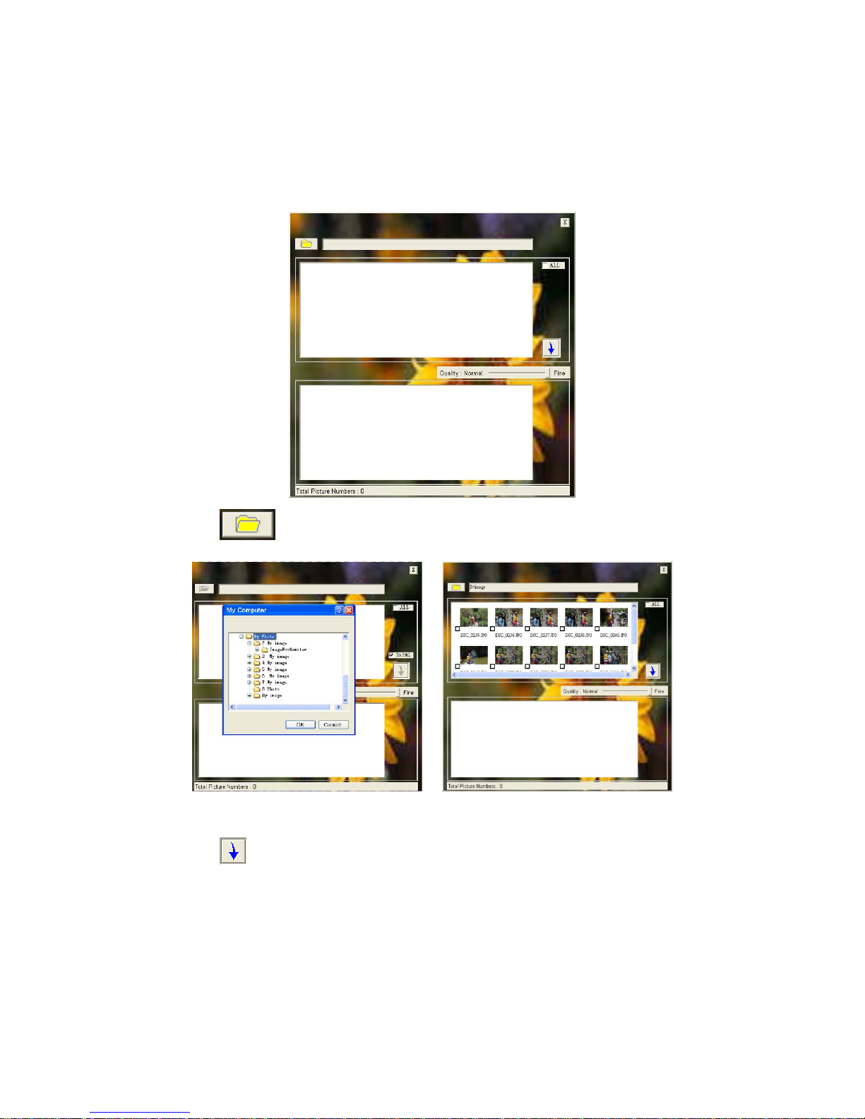
To use photo frame function, the video door phone needs specific formatted JPG image.
We provide the program PhotoManager to convert the image.
1. Start the program and you will see the bellow interface.
2. Click
on the left top corner to import a target image folder.
3. Click and select the images you want to convert (support BMP, JPG and GIF).
4. Click
to convert. It will generate the “MarsJPG” folder under the source image
folder.
5. Change the folder name to "PHOTO" and copy to the root directory of your TF card and
insert the TF card to the monitor, and then you can use the photo frame function.
 Loading...