

Page 1
Graymills
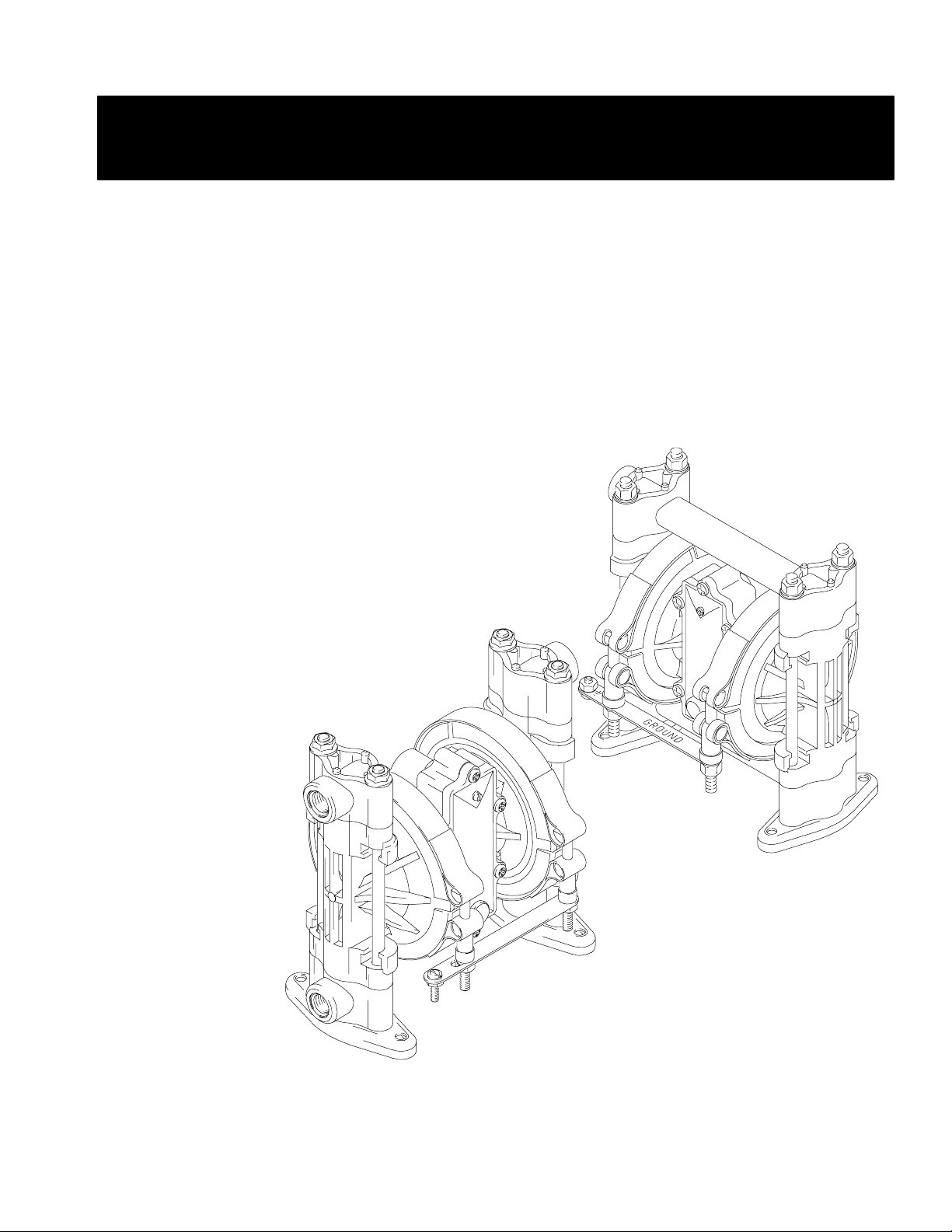
POLYPROPYLENE
Air Operated
Double Diaphragm Pumps
3/8" Model
Air Valve Service Instructions
100 psi (0.7 MPa, 7 bar) Maximum Fluid Working Pressure
100 psi (0.7 MPa, 7 bar) Maximum Air Input Pressure
795–90923
GM 3-07
Polypropylene Pumps, Series E
US and Foreign Patents Pending
WARNING/CAUTIONS
Read all these SAFETY INSTRUCTIONS
BEFORE installing or using this equipment. Keep this manual handy for reference/training.
01428B
TI2194A
Graymills Corporation 3705 N. Lincoln Avenue Chicago, Illinois 60613
773/248–6825 FAX 773/477–8673 www.graymills.com
Page 2
WARNING
EQUIPMENT MISUSE HAZARD
Any misuse of the equipment or accessories, such as overpressurizing, modifying parts, using incompatible
chemicals and fluids, or using worn or damaged parts, can cause them to rupture and result in splashing in
the eyes or on the skin, other serious injury, or fire, explosion or property damage.
D This equipment is for professional use only. Observe all warnings. Read and understand all instruction
manuals, warning labels, and tags before you operate this equipment. If you are not sure, or if you have
questions about installation or operation, call Graymills Corporation.
D Never alter or modify any part of this equipment; doing so could cause it to malfunction.
D Check all equipment regularly and repair or replace worn or damaged parts immediately.
D Never exceed the recommended working pressure or the maximum air inlet pressure stated on your pump
or in the Technical Data on page 4.
D Do not exceed the maximum working pressure of the lowest rated component in your system. This
equipment has a 100 psi (0.7 MPa, 7 bar) maximum working pressure at 100 psi (0.7 MPa, 7 bar, )
maximum incoming air pressure.
D Be sure that all fluids and solvents used are chemically compatible with the wetted parts shown in the
Technical Data on page 4. Always read the manufacturer’s literature before you use fluid or solvent in
the pump.
D Never move or lift a pump under pressure. If dropped, the fluid section may rupture. Always follow the
Pressure Relief Procedure on page 11 before you move or lift the pump.
FIRE AND EXPLOSION HAZARD
Static electricity is created by the flow of fluid through the pump and hose. If the equipment is not properly
grounded, sparking may occur. Sparks can ignite fumes from solvents and the fluid being pumped, dust
particles, and other flammable substances, whether you are pumping indoors or outdoors, and can cause a
fire or explosion and serious injury and property damage.
D To reduce the risk of static sparking, ground the pump and all other equipment used or located in the
work area. Check your local electrical code for detailed grounding instructions for your area and type of
equipment. See Grounding on page 6.
D If you experience any static sparking or even a slight shock while using this equipment, stop pumping
immediately. Check the entire system for proper grounding. Do not use the system again until you have
identified and corrected the problem.
D Pipe and dispose of the exhaust air safely, away from all sources of ignition. If the diaphragm fails, the
fluid is exhausted along with the air. See Air Exhaust Ventilation on page 10.
D Do not smoke in the work area. Do not operate the equipment near a source of ignition or an open flame,
such as a pilot light.
3
Page 3
SAFETY PRECAUTIONS
CAUTION
D Verify the chemical compatibility of the pump wetted parts and the substance being pumped, flushed or
recirculated. Chemical compatibility may change with temperature and concentration of the chemical(s)
within the substance being pumped, flushed or recirculated.
D The pump should not be used for the structural support of the piping system. Be certain system compo-
nents are properly supported to prevent stress on the pump parts.
D Do not allow pump to operate dry for long periods of time; this may cause unnecessary wear or damage
to the pump.
D Maximum temperature limits are based upon mechanical stress only. Certain chemicals will significantly
reduce maximum safe operating temperatures. Consult Graymills for chemical compatibility and temperature limits.
United States Government safety standards have been adopted under the Occupational Safety and Health Act. You should
consult these standards—particularly the General Standards, Part 1910, and the Construction Standards, Part 1926.
Technical Data For Pumps with Teflonr Diaphragms
Maximum fluid working pressure 100 psi (0.7 MPa, 7 bar). . . . . .
Air pressure operating range . . . 20 to 100 psi (0.14 to 0.7 MPa, .
1.4 to 7 bar ). . . . . . . . . . . . . . . . . . . . . . . . . . . . . . . . . . . . . . . . . .
Maximum air consumption 5.5 scfm (see chart). . . . . . . . . . . . . .
Maximum free flow delivery 6.5 gpm (24.6 lpm). . . . . . . . . . . . .
Maximum pump speed 330 cpm. . . . . . . . . . . . . . . . . . . . . . . . . .
Maximum suction lift 7 ft (2.1 m) dry, 12 ft (3.7 m) wet. . . . . . . .
Maximum size pumpable solids 1/16 in. (1.6 mm). . . . . . . . . . . .
Sound power level,
at full flow at 100 psi (0.7 MPa, 7 bar) 85 dBa. . . . . . . . . . . . .
Sound power level,
at 70 psi (0.48 MPa, 4.8 bar) and 1 gpm (3.8 lpm) 78 dBa. . .
Operating temperature range 40 to 150_ F (4.4 to 65.5_ C). . . . . . . .
Air inlet size . . . . . . . . . . . . . . . . . . . . . . . . . . . . . . 1/4 npt(f)
Fluid inlet and outlet size . . . . . . . . . . . . . . . . . . . 3/8” npt(f)
Wetted parts vary by models See pages 28 and 30. . . . . . .
Non-wetted external parts polyester (labels) glass–filled. .
polypropylene with conductive SST fibers
Weight (approximate) . . . . . . . . . . . . . 4.75 lb (2.2 kg). . . . .
Sound power level measured per ISO standard 9614–2.
VitonR, Teflon
DuPont Co.
Loctite
r is a registered trademark of the Loctite Corporation.
Santoprener is a registered trademark of the Monsanto Company.
Technical Data For Pumps with Hytrelr Diaphragms
Maximum fluid working pressure . . . . 100 psi (0.7 MPa, 7 bar)
Air pressure operating range . . . . 20 to 100 psi(0.14 to 0.7 MPa,
. . . . . . . . . . . . . . . . . . 1.4 to 7 bar). . . . . . . . . . . . . . . . . . . . . . .
Maximum air consumption . . . . . . . . . . . . 5.5 SCFM (see chart)
Maximum free flow delivery . . . . . . . . . . . . . 7 gpm (26.5 lpm)
Maximum pump speed . . . . . . . . . . . . . . . . . . . . . 330 cpm. . . .
Maximum suction lift 12 ft (3.7 m) dry; 21 ft (6.4 m) wet. . . . .
Maximum size pumpable solids . . . . . . . . . . . .1/16 in. (1.6 mm)
Sound power level,
at full flow at 100 psi (0.7 MPa, 7 bar) . . . . . . . . . . . . . 85
dBa
Sound power level,
at 70 psi (0.48 MPa, 4.8 bar) and 1 gpm (3.8 lpm) . . 78 dBa
Operating temperature range. 40 to 150_ F (4.4 to 65.5_ C)
Air inlet size . . . . . . . . . . . . . . . . . . . . . . . . . . . . . . 1/4 npt(f)
Fluid inlet and outlet size. . . . . . . . . . . . . . . . . . . . .3/8 npt(f)
Wetted Parts vary by model. . . . . . . . . See pages 27 and NO TAG.
Non-wetted external parts polyester (labels) glass–filled. .
polypropylene with conductive SST fibers
Weight (approximate) . . . . . . . . 4.75 lb (2.2 kg). . . . . . . . . . . . .
Sound power level measured per ISO standard 9614–2.
VitonR, Teflon
DuPont Co.
Loctiter is a registered trademark of the Loctite Corporation.
Santoprene
pany.
r, and Hytrelr are registered trademarks of the
r, and Hytrelr are registered trademarks of the
r is a registered trademark of the Monsanto Com-
4
Page 4
Maintenance
Lubrication
The air valve is designed to operate unlubricated, however
if lubrication is desired, every 500 hours of operation (or
monthly) remove the hose from the pump air inlet and add
two drops of machine oil to the air inlet.
CAUTION
Do not over-lubricate the pump. Oil is exhausted
through the muffler, which could contaminate your
fluid supply or other equipment. Excessive lubrication
can also cause the pump to malfunction.
Flushing and Storage
WARNING
To reduce the risk of serious injury whenever you are
instructed to relieve pressure, always follow the Pres-
sure Relief Procedure on page 11.
Flush the pump when necessary to prevent the fluid you are
pumping from drying or freezing in the pump and damaging it. Use a compatible solvent.
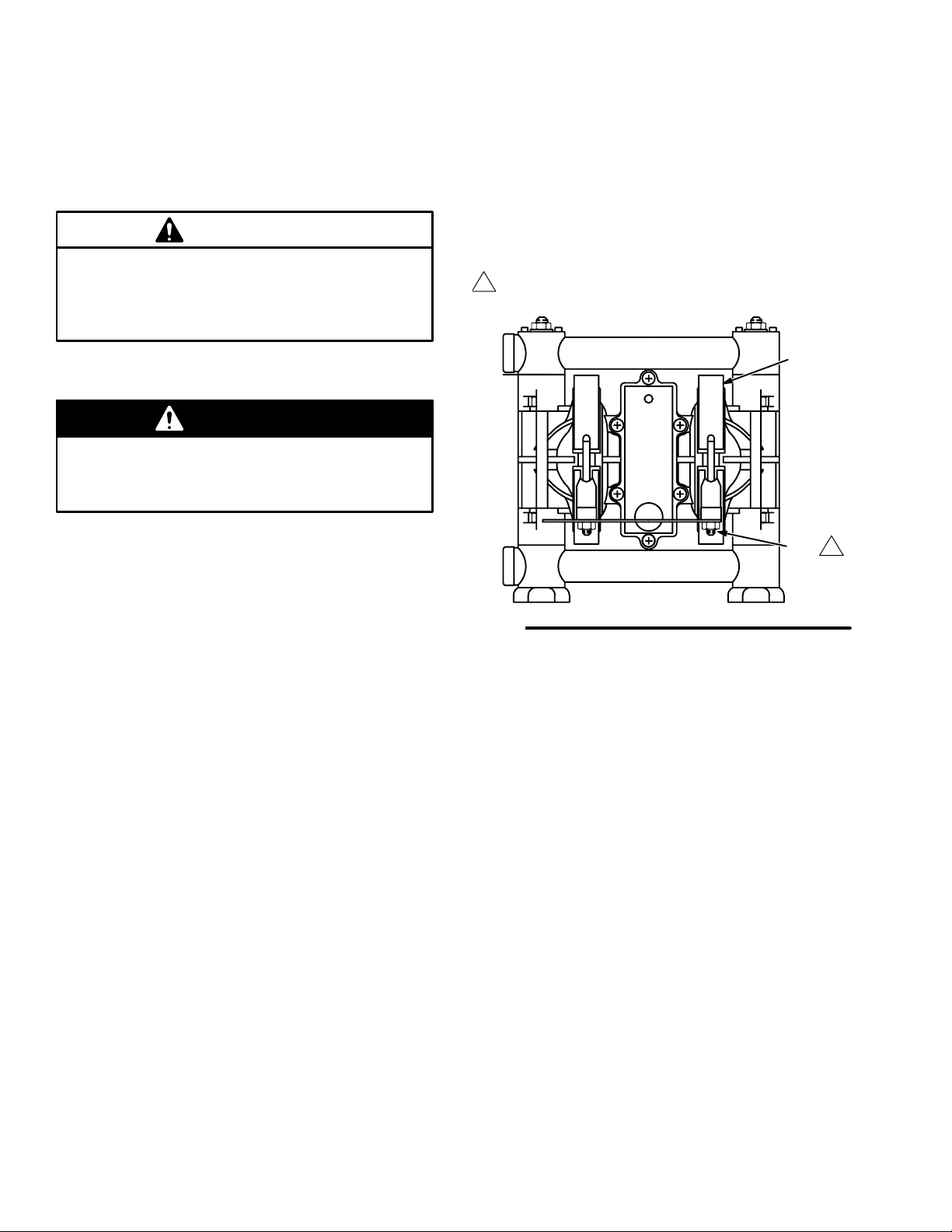
Tightening the Clamps
When tightening the clamps (111), apply thread lubricant to
the bolts and be sure to torque the nuts (113) to 50 to 60
in-lb (5.6 to 6.8 N-m). See Fig. 9.
Apply thread lube and torque nuts to 50 to 60
1
In-lb (5.6 to 6.8 N.m)
111
1113
Before storing the pump, always flush the pump and
relieve the pressure.
Tightening Threaded Connections
Before each use, check all hoses for wear or damage, and
replace as necessary. Check to be sure all threaded connections are tight and leak-free.
The recommended frequency for retorquing of fasteners
varies with pump usage; a general guideline is to retorque
every two months.
Fig. 9
01446B
Preventive Maintenance Schedule
Establish a preventive maintenance schedule, based on the
pump’s service history. This is especially important for
prevention of spills or leakage due to diaphragm failure.
14
Page 5
Operation
Pressure Relief Procedure
WARNING
PRESSURIZED EQUIPMENT HAZARD
The system pressure must be manually relieved to prevent the system from starting or spraying accidentally.
To reduce the risk of an injury from accidental spray
from the gun, splashing fluid, or moving parts, follow
the Pressure Relief Procedure whenever you
D Are instructed to relieve the pressure
D Stop spraying
D Check or service any of the system equipment
D Install or clean the spray tips
1. Shut off the air to the pump.
2. Open the dispensing valve, if used.
3. Open the fluid drain valve to relieve all fluid pressure,
having a container ready to catch the drainage.
Flush the Pump Before First Use
1. Be sure the pump is properly grounded. Read FIRE
OR EXPLOSION HAZARD on page 3.
2. Check all fittings to be sure they are tight. Be sure to
use a compatible liquid thread sealant or Teflonr tape
on all male threads. Tighten the fluid inlet and outlet
fittings snugly. Do not overtighten the fittings into the
pump.
3. Place the suction tube (if used) in the fluid to be
pumped.
4. Place the end of the fluid hose (N) into an appropriate
container. Close the fluid drain valve (J).
5. With the pump air regulator (H) closed, open all
bleed-type master air valves (B, E).
6. If the fluid hose has a dispensing device, hold it open
while continuing with the following step. Slowly open
the air regulator (H) until the pump starts to cycle.
Allow the pump to cycle slowly until all air is pushed
out of the lines and the pump is primed.
The pump was tested in water. If the water could contaminate the fluid you are pumping, flush the pump thoroughly
with a compatible solvent. Follow the steps under Starting
and Adjusting the Pump.
Starting and Adjusting the Pump
WARNING
TOXIC FLUID HAZARD
Hazardous fluid or toxic fumes can cause
serious injury or death if splashed in the
eyes or on the skin, inhaled, or swallowed.
Do not lift a pump under pressure. If dropped, the fluid
section may rupture. Always follow the Pressure Relief
Procedure above before lifting the pump.
If you are flushing, run the pump long enough to
thoroughly clean the pump and hoses. Close the air
regulator. Remove the suction tube from the solvent
and place it in the fluid to be pumped.
Pump Shutdown
WARNING
To reduce the risk of serious injury whenever you are
instructed to relieve pressure, always follow the Pres-
sure Relief Procedure at left.
At the end of the work shift, relieve the pressure.
11
Page 6
Service
Replacing the Air Valve
Tools Required
D Torque wrench
D Phillips screwdriver
D O-ring pick
NOTE: Air Valve Kit 239952 is available. Parts included
in the kit are marked with a dagger, for example (2{). A
tube of general purpose grease (26{) is supplied in the kit.
Install the kit as follows.
WARNING
To reduce the risk of serious injury whenever you are
instructed to relieve pressure, always follow the Pres-
sure Relief Procedure on page 11.
1. Relieve the pressure.
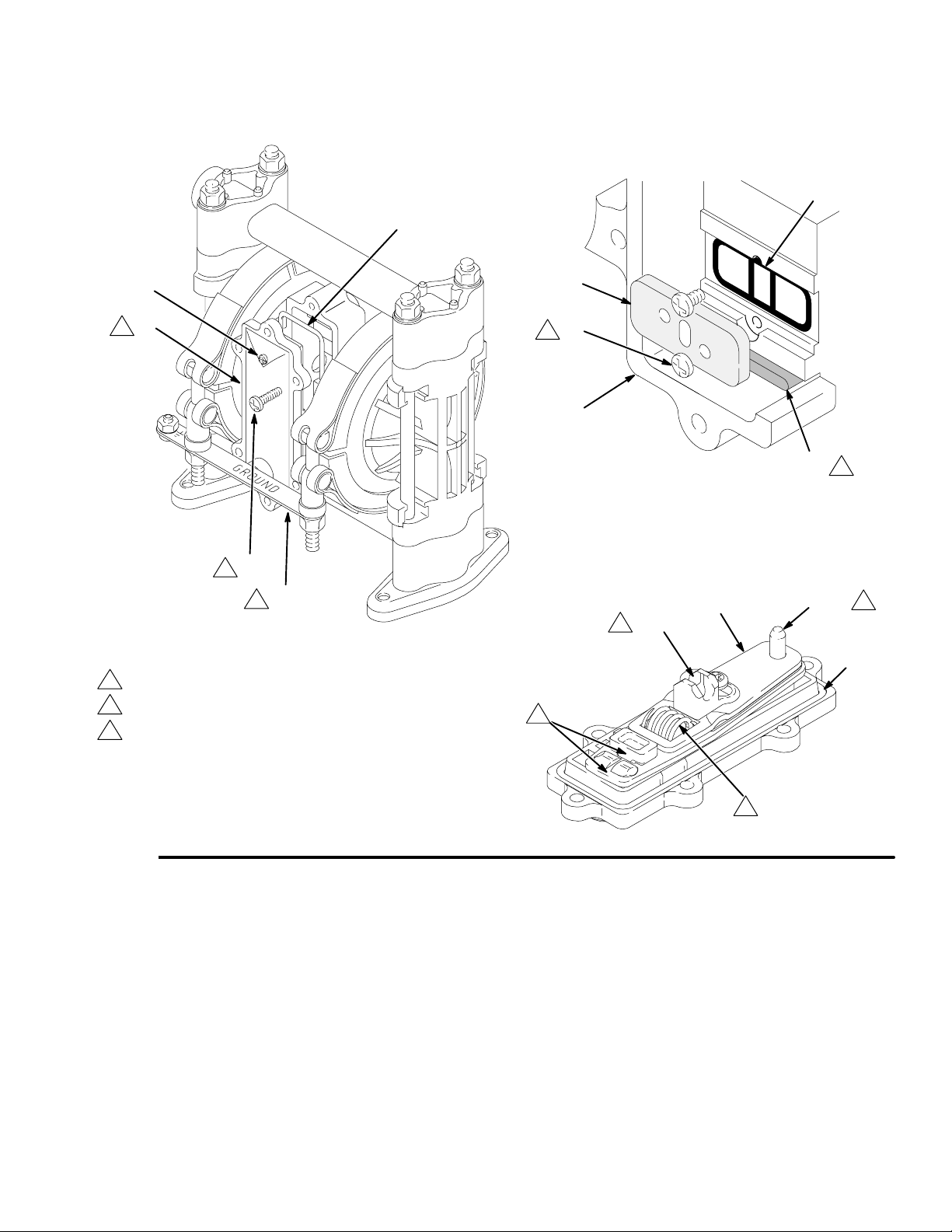
2. Unscrew the six mounting screws (15) and remove the
air valve (A) from the pump. See Fig. 10.
3. Refer to the Valve Plate Detail in Fig. 10. Remove the
two screws (10) holding the valve plate (13) to the
pump. Use an o-ring pick to remove the valve plate,
seal (12), and bearing (9).
4. Apply grease (26{) to the bearing (9{). Install the
bearing and the seal (12) in the pump housing (1).
Install the valve plate (13) and secure with the two
screws (10{), as shown. Torque the screws to 5 to 7
in-lb (0.6 to 0.8 N-m).
5. Make certain the o-ring (19{) is in place on the air
valve cover (2{).
6. Apply grease (26{) where shown in Fig. 10.
7. Align the new air valve assembly so the reset shaft
(21{) is at the top. Install the valve on the pump,
making sure the valve saddle (14{) engages the
recessed area on the diaphragm shaft (23). Install the
six screws (15) and torque oppositely and evenly, to 8
to 14 in-lb (0.9 to 1.6 N-m).
16
Page 7
Service
19{
VALVE PLATE DETAIL
12
{21
4
A
15
1
112
4
1
Torque oppositely and evenly to 8 to 14 in-lb (0.9 to 1.6 N-m).
2
Torque to 5 to 7 in-lb (0.6 to 0.8 N-m).
3
Apply grease (26{).
01436B
13
10
2
1
3
9{
01458
GREASE APPLICATION
3
{16
3
{14
21{
19{
3
Fig. 10
3
03412A
17
Page 8
Service
Repairing the Air Valve
Tools Required
D Torque wrench
D Phillips screwdriver
D O-ring pick
D Rubber mallet
Disassembly
WARNING
To reduce the risk of serious injury whenever you are
instructed to relieve pressure, always follow the Pres-
sure Relief Procedure on page 11.
1. Relieve the pressure.
NOTE: ALL PARTS SHOWN ARE INCLUDED
IN AIR VALVE KIT 239952.
2. Remove the air valve from the pump (see page 16).
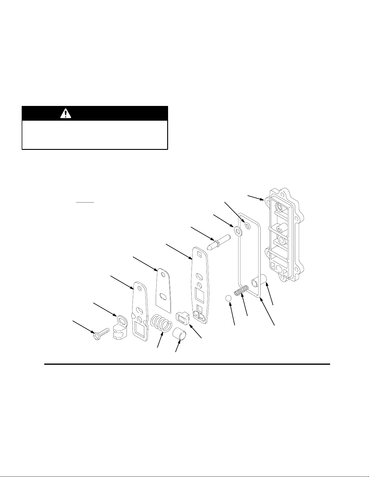
3. Remove the screw (15) and shift saddle (14). See Fig.
11.
4. Disassemble the link assembly, consisting of the
actuator link (16), spacer (17), detent link (22), spring
(3), stop (4), and valve cup (5).
5. Remove the detent ball (8) and spring (6). The detent
collar (7) is a press-fit and should not need removal; if
it does require replacement, you should also replace
the cover (2).
6. Remove the reset shaft (21), o-ring (20) and washer
(18).
7. Clean all parts and inspect for wear or damage.
Replace as needed. See Reassembly, page 19.
{2
{20
Fig. 11
{15
{14
{16
{17
{22
{3
{4
{21
{18
5{
8{
7{
6{
19{
01431A
18
Page 9
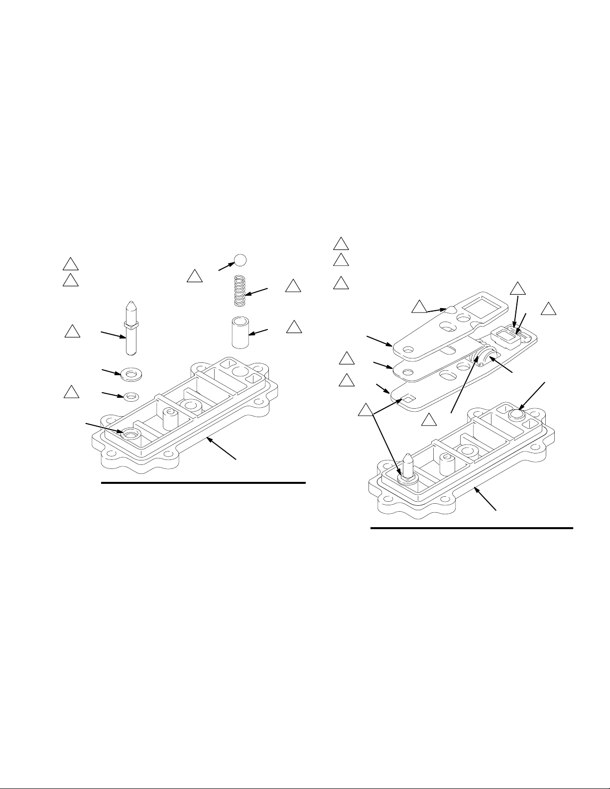
Reassembly
Service
1. If the detent collar (7) was removed, carefully install a
new collar in a new cover (2), using a rubber mallet.
See Fig. 12.
2. Grease the spring (6) and place it in the collar (7).
Grease the ball (8) and set it on the spring.
3. Grease the o-ring (20) and install it in the hole (H) in
the cover (2). See Fig. 12. Slide the washer (18) onto
the blunt end of the reset shaft (21). Insert the shaft
through the cover (2) until it seats.
4. Grease the spring (3). Place the link stop (4) inside the
spring.
1
Apply grease (26{).
2
Press fit with rubber
mallet.
{21
1
{8
1
6{
7{
1
2
{18
{20
1
6. Squeeze the spring (3) and install it and the stop (4) in
the link assembly. The spring tension will hold all
these parts together. Grease the valve cup (5) and
install it in the link assembly as shown.
7. Install the link assembly on the cover (2) so the
pointed end of the reset shaft (21) fits through the holes
in the links and the square part of the shaft engages the
square hole. Make certain the bumps on the detent link
(22) engage the ball (8).
1
Apply grease (26{).
2
Bumps face up.
Reset shaft square must engage with
3
square hole.
2
2
1
5{
{16
1
{17
1
{22
4{
8{
H
2{
Fig. 12
5. Grease the detent link (22) and link spacer (17).
Assemble the detent link, link spacer, and actuator link
(16) as shown in Fig. 13. The raised bumps on the links
(22 and 16) must face up.
01437
Fig. 13
3
1
{3
2{
7505A
19
Page 10
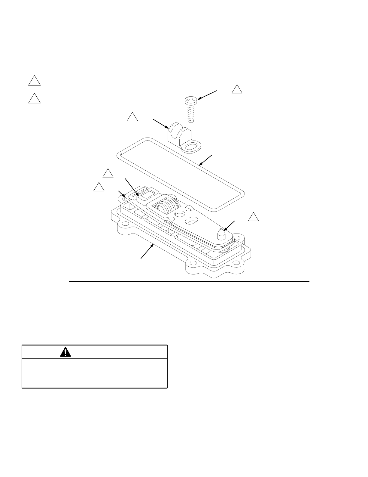
Service
8. Grease the inside surfaces of the shift saddle (14) and
install it as shown in Fig. 14. Hold the link assembly
firmly in place and install the screw (15). Torque to 7
to 9 in-lb (0.8 to 1.0 N-m). Install the o-ring (19) on
the cover (2).
1
Apply grease (26{).
Torque to 7 to 9 in-lb (0.8 to 1.0 N-m).
2
{14
1
1
{5
{22
1
9. Reinstall the air valve as explained on page 16.
15{
2
19{
{2
Fig. 14
CAUTION
Do not over-torque the manifold bolts (104). Doing so
may cause the nuts (106) to spin in the housings,
damaging the cover (101).
21{
1
7506A
20
Page 11
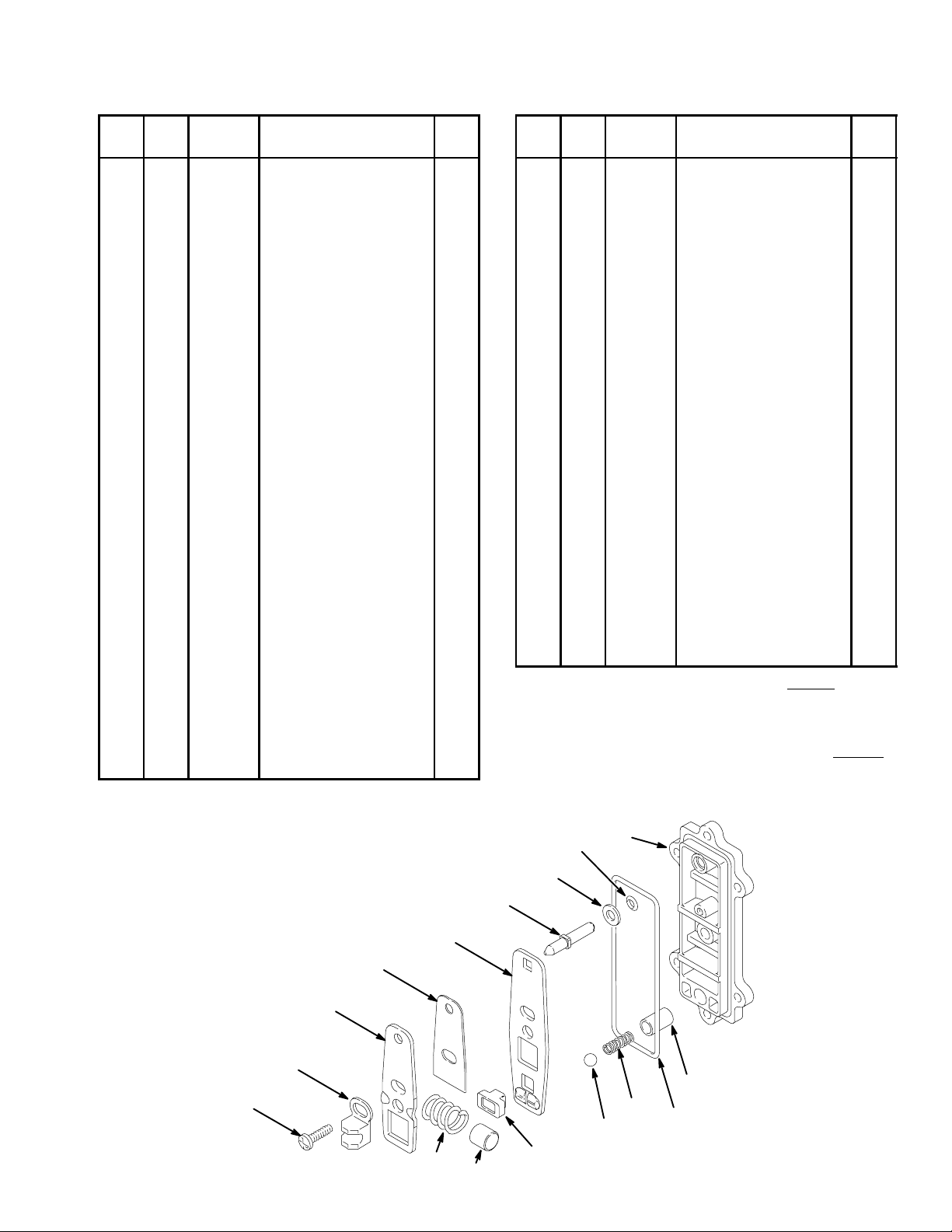
Air Motor Parts List (Matrix Column 2)
Parts
Ref.
No.
Digit
3 1 HOUSING, center;
Part No. Description Qty
polypropylene;
see page 28
2{ COVER, air valve;
polypropylene
3{ SPRING, compression;
sst
4{ STOP, link; 1
5{ CUP, valve; 1
6{ SPRING, compression;
sst
7{ COLLAR, detent; sst 1
8{ BALL, detent; carbide 1
9{ BEARING, link;
see page 28
10 SCREW, thread-forming;
1/4–20; 0.375 in. (9.5
mm) long; see page 28
11 MUFFLER; see page 28 1
12 SEAL, plate, valve;
buna-N; see page 28
13 PLATE, valve; sst;
see page 28
14{ SADDLE, shift; 1
15{ SCREW, thread-forming;
10–14 size; 0.75 in.
(19 mm) long; see below
and page 28
Ref.
No.
Digit
1
1
1
1
1
2
1
1
{ These parts are included in Air Valve Kit 239952, which
7
may be purchased separately. The kit includes only one
screw (15), shown below, and a tube of grease (26).
} These parts are included in Diaphragm Shaft Kit 239014,
which may be purchased separately.
Part No. Description Qty
16{ LINK, actuator; sst 1
17{ SPACER, link; 1
18{ WASHER, plain; sst 1
19{ O-RING; buna-N 1
20{ O-RING; buna-N 1
21{ SHAFT, reset; sst 1
22{ LINK, detent; sst 1
23} SHAFT, diaphragm; sst;
see page 28
26{ GREASE, general pur-
pose; 0.375 oz. (10.5 g);
not shown
27 NUT, hex; 10–24;
see page 28
28 SCREW; 10–24;
0.75 in. (19 mm) long;
see page 28
29 LOCKWASHER, int.
tooth; no. 10; see page
28
30} PACKING, u-cup; VitonR 2
31} BEARING; 2
1
1
1
1
1
{15
{14
{16
{17
{22
{3
{4
{21
{18
5{
{20
{2
8{
6{
7{
19{
01431A
27
Page 12
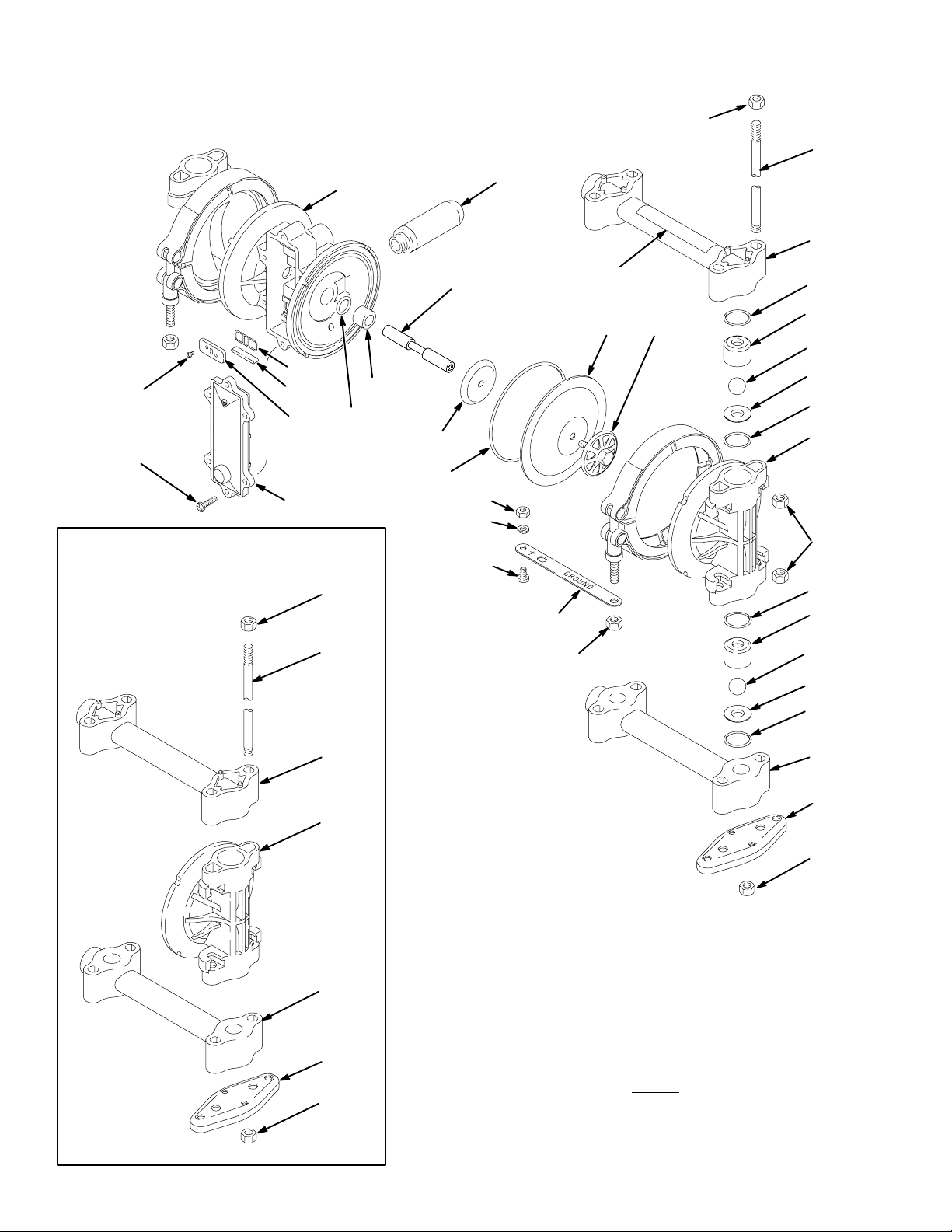
Parts
106
104
10
15
Detail of Polypropylene Models
12
9{
13
{
106
104
1
30}
31}
118
*404
23}
27[
29[
28[
11
112[
113
Y109
401*
102
108*
202*
103
301*
201*
108*
101
106
108*
202*
301*
201*
102
101
102
107
106
* Included in Pump Repair Kit, which may be purchased
separately.
{ Included in Air Valve Kit 239952, which may be pur-
chased separately. See parts list on page 27.
Y Replacement Danger and Warning labels, tags and
cards are available at no cost.
} Included in Diaphragm Shaft Kit 239014
purchased separately.
[ Not supplied with Polypropylene pump.
, which may be
108*
102
107
106
01429E
28
Page 13
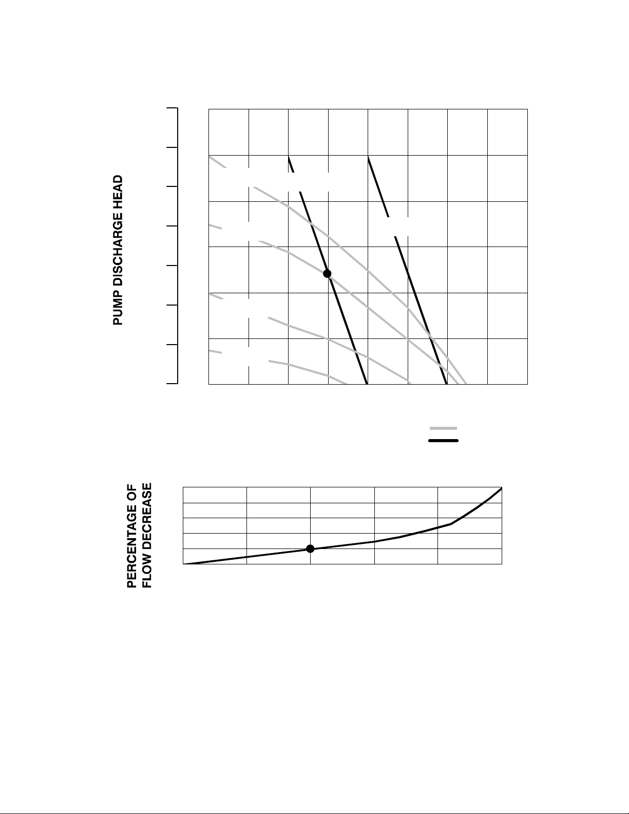
Performance Chart – pumps with Teflon Diaphragms
Example of Finding Pump Air Consumption and Air Pressure at a Specific Fluid Deliv-
feet
(meters)
280
(85.3)
psi
(bar)
120
(8.4)
ery and Discharge Head: To supply 3 gpm (11.4 liters) fluid flow (horizontal scale) at 50 psi
(3.5 bar) discharge head pressure (vertical scale) requires 3 scfm (.084 m
sumption at 70 psi (4.9 bar) inlet air pressure.
#/min) air con-
240
(73.2)
200
(61.0)
160
(48.8)
120
100
(7.0)
80
(5.6)
60
(4.2)
100 psi air
(7 bar)
70 psi air
(4.9 bar)
(36.6)
40
80
(24.4)
40
(12.2)
0
TEST CONDITIONS
Pump tested in water with inlet submerged.
(2.8)
40 psi air
(2.8 bar)
20
(1.4)
20 psi air
(1.4 bar)
0
012345678
(3.8) (11.4) (19.0) (26.5)
3 scfm
(.084 m
#/min)
5 scfm
(0.14 m
(7.6) (15.2) (22.7) (30.3)
#/min)
FLUID FLOW GPM (lpm)
KEY FLUID PRESSURE AND FLOW
SCFM AIR CONSUMPTION
PUMPING RATE DECREASE AT DIFFERENT SUCTION LIFTS
EXAMPLE: At a suction lift of 10 ft (3.05 m), the pump flow rate will be decreased by 20 percent.
100
80
60
40
20
0
0 5 10 15 20 25
(1.52) (3.05) (4.57) (6.1) (7.62)
SUCTION LIFT IN FEET (METERS)
29
Page 14
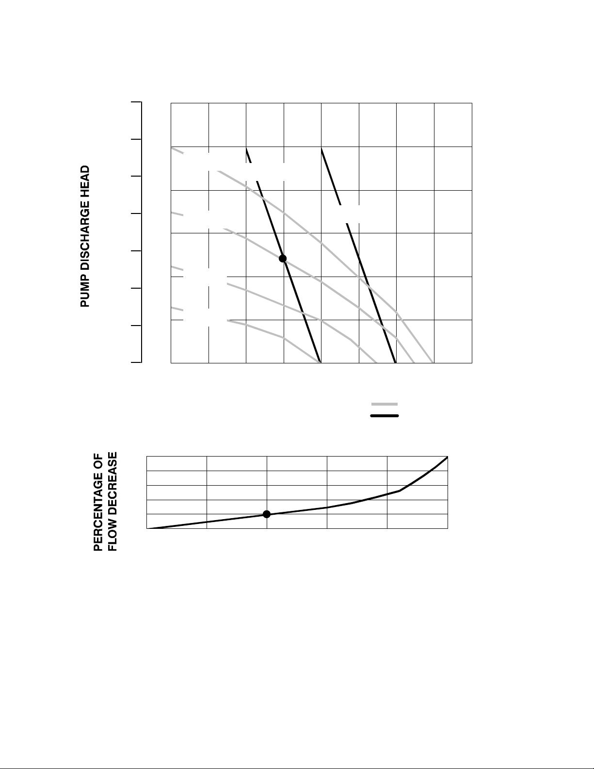
Performance Charts – pumps with Hytrel Diaphragms
Example of Finding Pump Air Consumption and Air Pressure at a Specific Fluid Deliv-
feet
(meters)
280
(85.3)
psi
(bar)
(8.4)
ery and Discharge Head: To supply 3 gpm (11.4 liters) fluid flow (horizontal scale) at 50 psi
(3.5 bar) discharge head pressure (vertical scale) requires 3 scfm (.084 m
tion at 70 psi (4.9 bar) inlet air pressure.
120
#/min) air consump-
240
(73.2)
200
(61.0)
160
(48.8)
120
100
(7.0)
80
(5.6)
60
(4.2)
100 psi air
(7 bar)
70 psi air
(4.9 bar)
3 scfm
(.084 m
#/min)
5 scfm
(0.14 m
#/min)
(36.6)
40 psi air
40
80
(2.8)
(2.8 bar)
(24.4)
20 psi air
20
40
(12.2)
0
(1.4)
(1.4 bar)
0
012345678
(3.8) (11.4) (19.0) (26.5)
(7.6) (15.2) (22.7) (30.3)
FLUID FLOW GPM (lpm)
TEST CONDITIONS
Pump tested in water with inlet submerged.
KEY FLUID PRESSURE AND FLOW
SCFM AIR CONSUMPTION
PUMPING RATE DECREASE AT DIFFERENT SUCTION LIFTS
EXAMPLE: At a suction lift of 10 ft (3.05 m), the pump flow rate will be decreased by 20 percent.
100
80
60
40
20
0
0 5 10 15 20 25
(1.52) (3.05) (4.57) (6.1) (7.62)
SUCTION LIFT IN FEET (METERS)
30
Page 15

WARRANTY
Graymills Corporation warrants that the equipment manufactured and
delivered, when properly installed and maintained , shall be free from
defects in workmanship and will function as quoted in the published specification. Graymills does not warrant process performance, nor assume any
liability for equipment selection, adaptation, or installation.
Warranty does not apply to damages or defects caused by shipping, operator carelessness, mis–use, improper application or installation, abnormal
use, use of add–on parts or equipment which damages or impairs the proper function of the unit and modifications made to the unit. Warranty does
not apply to expendable parts needing replacement periodically due to
normal wear and tear.
A new Warranty period shall not be established for repaired or replaced
materials or products. Such items shall remain under Warranty for only the
remainder of the Warranty period of the original materials or product.
THE FOREGOING WARRANTIES ARE IN LIEU OF ALL OTHER
WARRANTIES, WHETHER ORAL, WRITTEN, EXPRESSED, IMPLIED
OR STATUTORY. GRAYMILLS CORPORATION MAKES NO OTH-
ER WARRANTY OF ANY KIND EXPRESS OR IMPLIED. ALL IMPLIED WARRANTIES OF MERCHANTABILITY AND
Graymills Corporation 3705 N. Lincoln Avenue Chicago, Illinois 60613 773/248–6825 FAX 773/477–8673 www.graymills.com
FITNESS FOR A PARTICULAR PURPOSE WHICH EXCEED THE A
FORESTATED OBLIGATION ARE HEREBY DISCLAIMED BY GRAY-
MILLS CORPORATION AND EXCLUDED FROM THIS SALE.
Graymills warranty obligations and Buyer remedies (except to title) are
solely and exclusively stated herein. In no case will Graymills be liable
for consequential damages, loss of production, or any other loss incurred
due to interruption of service.
Graymills’ obligation under this Warranty shall be limited to:
a) Repairing or replacing (at Graymills sole discretion) any non–conforming or defective component within one year from the date of
shipment from Graymills.
b) Repairing or replacing (at Graymills sole discretion), components
supplied by, but not manufactured by Graymills, to the extent of the
warranty given by the original manufacturer.
Buyer must give Graymills prompt notice of any defect or failure.
If you believe that you have a Warranty claim, contact Graymills at
(773)248–6825. Any return material must have an RMA number on the
outside of the package and must be shipped prepaid or shipment will be
refused. Graymills will promptly examine the material and determine if it
is defective and within the Warranty period.
32
 Loading...