

Thunderbird Radio
Product Guide v0.70 (Preliminary)
Bulletin #1033
For Grayhill Part Numbers:
OEM RF Unit - WM09STDB-0001
CF Card – WM09STDB-0002
561 Hillgrove Avenue
LaGrange, IL 60525
Phone: (708) 354-1040
Fax: (708) 354-2820
E-mail: ezcom@grayhill.com
On the Internet: http://www.grayhilloem.com

EZCom Thunderbird Radio – Product Guide v0.68
Copyright © 2004 Grayhill, Inc. All rights reserved.
The information supplied in this manual is believed to be reliable and accurate at the time of its publication. Grayhill, Inc. assumes no
responsibility for any errors, omissions, or suitability of its products for a particular application.
Warranty
EZCom Thunderbird radios from Grayhill, Inc., (the “Product”) are warranted against defects in materials and workmanship under normal
use, for a period of 1 year from the date of purchase. This warranty does not apply to units that have been abused or stressed beyond the
published environmental and electrical specifications. In the event of a product failure due to materials or workmanship, Grayhill will repair
or replace the defective product. This warranty is limited to the original purchase price of the unit and does not cover installation, labor or
any other contingent costs. For warranty service, return the defective product to Grayhill, shipping prepaid, for prompt repair or replacement.
The foregoing sets forth the full extent of Grayhill’s warranties regard the Product. Repair or replacement at Grayhill’s option is the
exclusive remedy.
THIS WARRANTY IS GIVEN IN LIEU OF ALL OTHER WARRANTIES, EXPRESS OR IMPLIED, AND GRAYHILL SPECIFICALLY
DISCLAIMS ALL WARRANTIES OF MERCHANTABILITY OR FITNESS FOR A PARTICULAR PURPOSE. IN NO EVENT SHALL
GRAYHILL, ITS SUPPLIERS OR LICENSORS BE LIABLE FOR DAMAGES IN EXCESS OF THE PURCHASE PRICE OF THE
PRODUCT, FOR ANY LOSS OF USE, LOSS OF TIME, INCONVENIENCE, COMMERCIAL LOSS, LOST PROFITS OR SAVINGS,
OR OTHER INCIDENTAL, SPECIAL OR CONSEQUENTIAL DAMAGES ARISING OUT OF THE USE OR INABILITY TO USE THE
PRODUCT, TO THE FULL EXTENT SUCH MAY BE DISCLAIMED BY LAW. SOME STATES DO NOT ALLOW THE EXCLUSION
OR LIMITATION OF INCIDENTAL OR CONSEQUENTIAL DAMAGES. THEREFORE, THE FOREGOING EXCLUSIONS MAY
NOT APPLY IN ALL CASES.
This warranty provides specific legal rights. Other rights which vary from state to state may also apply.
Ordering Guide
All programs and files on the CD included with this Product are protected by copyright. Grayhill, Inc. authorizes duplication of the contained
programs and files as necessary for use by the licensee; however, general distribution of these programs and/or files is strictly forbidden
without prior written consent from Grayhill, Inc.
Grayhill
Grayhill Product Part Number
EZCom Thunderbird OEM RF Module WM09STDB-0001
EZCom Thunderbird CF Card WM09STDB-0002
Standard Interface Board WLYY4097-1
AC Power Supply for Interface Board WL-PWR-9V
Product CD (contains Test File and Product Guide PDF) WL-WRD
Evaluation Kit - 2 RF Modules, 2 Standard Interface Boards, 2 DB-9 Cables, 2 AC Adapters, 2 Whip Antennas, 1 CD WLYY4098-1
For antenna options other than a whip antenna, contact Grayhill for the currently available antenna/coax choices.
Audience
This manual provides a source for information about the Grayhill Thunderbird Radio Module. The information it provides is intended for
qualified electrical personnel familiar with embedded device integration.
© 2004 Grayhill, Inc., Confidential and Proprietary Page
2

EZCom Thunderbird Radio – Product Guide v0.68
Contents
EZCom Thunderbird Introduction............................................................................................5
Application Use .......................................................................................................................................5
RF Module Features................................................................................................................................. 5
Electrical and Mechanical Interfaces.........................................................................................6
Connectors and Pinouts............................................................................................................................ 6
Antennas ..................................................................................................................................................9
Mechanical Interface.............................................................................................................................. 10
RF Module Mechanical Drawings .........................................................................................................10
RF Module 3-D Models .........................................................................................................................11
Standard Interface Board.........................................................................................................11
Setting the J5 Jumper .............................................................................................................................11
Connectors and Pinouts.......................................................................................................................... 12
Interface Board Mechanical Drawings................................................................................................... 12
Interface Board 3-D Models...................................................................................................................13
Serial Interface ....................................................................................................................................... 13
Configuration.............................................................................................................................14
AT Commands ....................................................................................................................................... 14
Binary Commands..................................................................................................................................15
Operation....................................................................................................................................17
Standby Mode ........................................................................................................................................ 17
Transmit Mode....................................................................................................................................... 17
Receive Mode ........................................................................................................................................18
Low-Power Modes.................................................................................................................................18
Networking.................................................................................................................................20
Vendor Identification Numbers.............................................................................................................. 20
Subnet IDs..............................................................................................................................................20
Radio Group Numbers ...........................................................................................................................20
Radio Addresses.....................................................................................................................................21
Radio Address Masks.............................................................................................................................22
Using the EZCom Thunderbird Evaluation Kit.....................................................................22
Evaluation Kit Contents.........................................................................................................................22
Evaluation Test Requirements ...............................................................................................................22
Assembly Instructions............................................................................................................................22
Appendix A. EZCom Thunderbird CF....................................................................................26
CF Interface ...........................................................................................................................................26
RF Connector and Antennas ..................................................................................................................26
PDA Support..........................................................................................................................................26
Configuring a Terminal Connection.......................................................................................................26
Opening a Terminal Connection ............................................................................................................27
Configuring the Thunderbird CF............................................................................................................27
Testing Thunderbird CF Data Transfer..................................................................................................27
Appendix B. Specifications........................................................................................................28
Appendix C. Data Packet Timing Diagrams...........................................................................29
Appendix D. Mechanical Drawings..........................................................................................30
Appendix E. Agency Certification............................................................................................32
FCC Notices........................................................................................................................................... 32
OEM Labeling Requirements.................................................................................................................33
© 2004 Grayhill, Inc., Confidential and Proprietary Page
3

EZCom Thunderbird Radio – Product Guide v0.68
© 2004 Grayhill, Inc., Confidential and Proprietary Page
4

EZCom Thunderbird Introduction
EZCom Thunderbird Radio – Product Guide v0.68
Grayhill’s EZCom Thunderbird radio is a frequency-hopping wireless module that transfers
standard asynchronous
1
serial data streams over-the-air between host devices. The data radio is
available in two formats:
• The Thunderbird – for host devices that have an available serial port
• The Thunderbird CF – for Windows CE handheld devices
Small in size and easily integrated into existing hardware, both Thunderbirds operate in the 900
MHz ISM frequency band and offer data rates up to 19200 bps, and ranges up to 24 miles
outdoors and 1800 feet indoors. The Thunderbird’s Frequency Hopping Spread Spectrum
(FHSS) technology achieves exceptionally secure data communication, resistant to noise and
interference.
Application Use
Wireless communications solve many otherwise impossible industrial and commercial
communications problems. Radio waves can transport data over long distances, through the heat
of blast furnaces and the cold temperatures that often prevail at outdoor installations. The
standard Thunderbird provides RF communications for fixed needs, such as manufacturing
control and security, business, and environmental monitoring. The Thunderbird CF allows
mobile personnel and portable equipment to communicate wirelessly.
Note: The standard Thunderbird’s functionality is covered in the first part of this manual.
Appendix A presents a brief description of the Thunderbird CF, and refers the reader to prior
sections when functionality is shared with the standard Thunderbird.
RF Module Features
Receiver Sensitivity: 10
Transmit Power: 160 mW (22 ± 2 dBm)
Frequency: 902-928 MHz for the standard module; 902-921 MHz for the anti-pager module
RF Range: Indoor/Urban – up to 1800 feet; Outdoor Line-Of-Sight – up to 24 miles
Serial Port: The module incorporates a 3.3V CMOS serial port for easy CPU interfacing.
Selectable Serial Data Rates: 2400, 4800, 9600, 19200, 38400, and 57600 bps
Signal Levels: 8 digital I/O with 5V-tolerant 3.3V CMOS signal levels; 3 additional digital I/O
that double as 12-bit A/D inputs
The module communicates directly with any UART interfaced host device through its serial
port, or with any RS-232 interfaced host device via the optional Grayhill standard interface
board.
Note: The RF module can provide simple, built-in I/O functions via its standard 100 mil. pitch
interface header, with no separate controller needed. Contact Grayhill for more information.
1
If a synchronous serial interface is required, please contact the EZCom Thunderbird project manager.
2
Upon request, Grayhill can supply an anti-pager RF module with a custom SAW filter designed to suppress the impact of pager and cell phone systems when
the Thunderbird is deployed very close to pager or cell transmitters.
-6
BER, –105 dBm
2
© 2004 Grayhill, Inc., Confidential and Proprietary Page
5
EZCom Thunderbird Radio – Product Guide v0.68
Electrical and Mechanical Interfaces
The EZCom Thunderbird uses commonly available connectors and fasteners, and has been
otherwise optimized for easy integration into other systems.
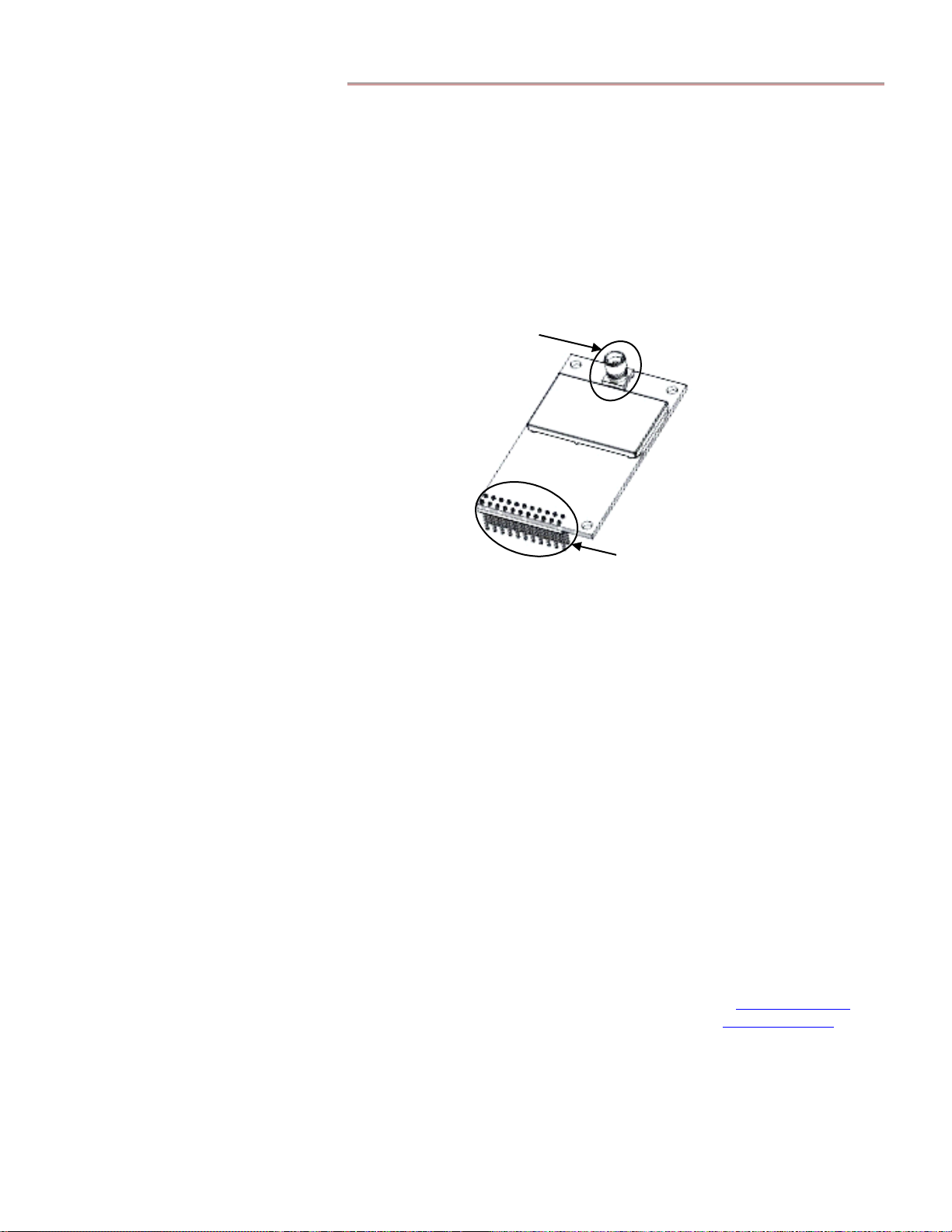
Connectors and Pinouts
The Thunderbird RF module incorporates two connectors: the RF connector and the main
interface connector, as shown in Figure 1 below.
RF
Connector
Main
Interface
Connector
Figure 1. Thunderbird Connectors
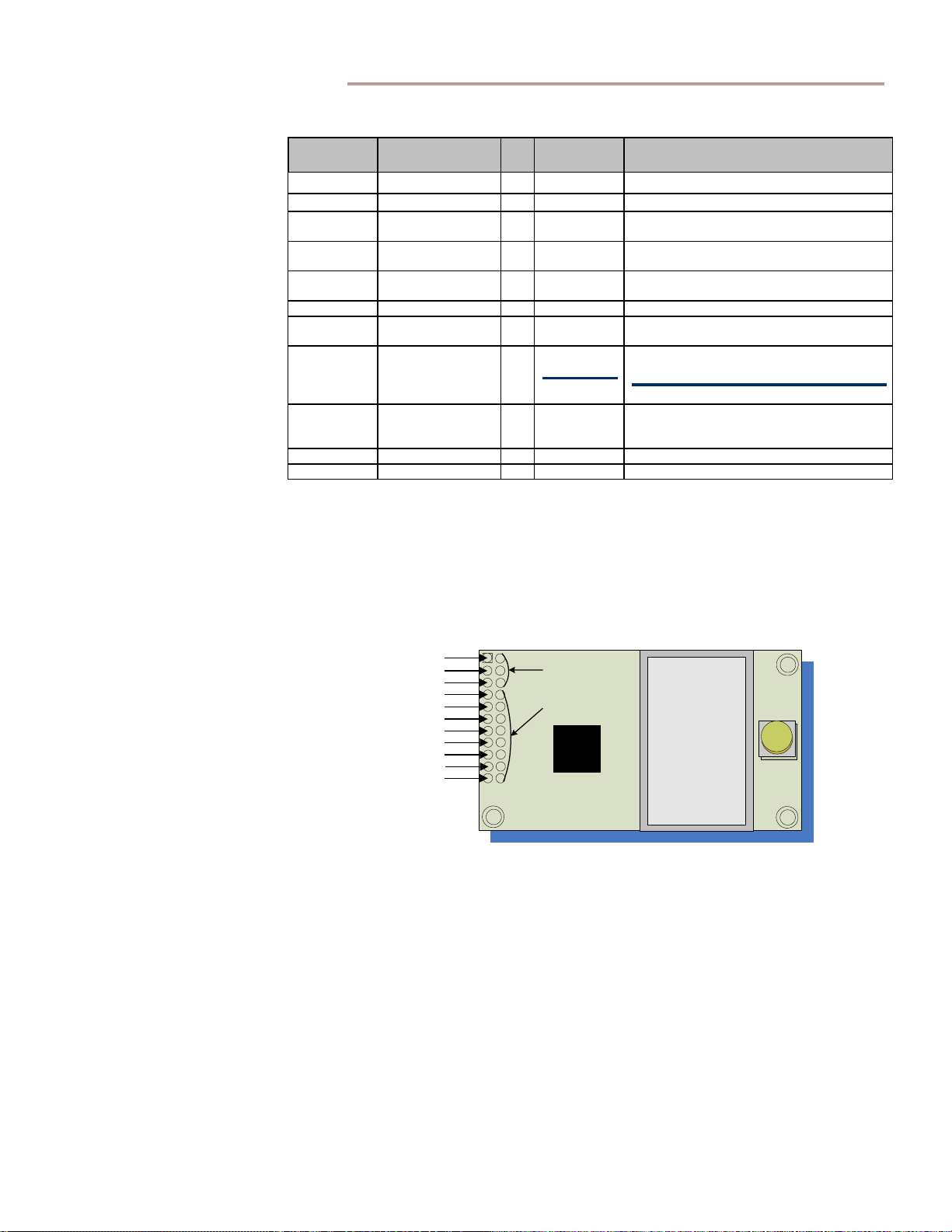
Main Interface Connector
The RF module connects to a host device via a 2 x 11, 0.100" pitch male header with 0.025"
square pins. The connector supplies power and I/O, and also is the means whereby a UARTinterfaced device can connect directly to the module. The header is gold-flashed for lower
contact resistance.
The outer row of pins (A1 – A11) on the main interface connector performs basic radio
functionality. The inner row of pins (B1 – B11) provides RS-485/422 support; customized
versions can provide analog inputs and digital I/O. See Table 1 and Figure 2 on page 7 for more
information.
Mating Connectors
For the host device, a female 22-pin connector that uses at least two points of contact per pin is
recommended. In high vibration and shock applications, consider using one of the more
expensive 22-pin connectors with 4 points of contact, or else solder the header into your PCB.
Example female 22-pin connectors with 2 points of contact per pin are listed here:
Female 22-Pin Connectors with 2 Points of Contact
Digi-Key PN 15-44-4111-ND Available at Digi-Key, 800-344-4539 or www.digikey.com
Samtec PN CES-111-01-G-D Available at Samtec, 800-726-8329 or www.samtec.com
© 2004 Grayhill, Inc., Confidential and Proprietary Page
6
EZCom Thunderbird Radio – Product Guide v0.68
Module
Pin
Table 1.
Signal Name
J2 Pin Signal Descriptions
I/
O
When
Active
Description
A1 FOUT O* Low Flow Control Out
A2 Power Down I* High When driven high, module powers down.
A3 DO (Data Out) O* N/A
A4 DI (Data In) I N/A
A5 FIN I** Low
Serial data leaving Thunderbird module
(to host, from over-the-air)
Serial data entering Thunderbird module
(from host, to over-the-air)
Flow Control In /
Binary Command Mode Control
A6 RESET I* Low Resets module parameters to defaults
A7 RX O High
Low
A8 TX / PWR O
High
A9 CONFIG
I**
*
Low
Receive LED pulses high during RF
reception.
Transmit LED pulses low during
transmission.
At power-up, PWR driven high; remains high
Hold low during reboot to enter AT Command
Mode (backup method for command
sequence)
A10 VCC I - 4.5-15 VDC ± 5% V regulated
A11 GND - - Ground
* Pin uses a 10K Ω Pull-Up resistor (already installed in the module).
** Pin uses a 10K Ω Pull-Down resistor (already installed in the module).
*** Pin uses a 100K Ω Pull-Up resistor (already installed in the module).
Note: When integrating the Thunderbird with a host PC board, ensure all unused lines are left
disconnected (floating).
A
1
F
-
U
O
2
A
W
P
-
A
3
-
D
A
4
-
A
6
A
8
A
9
A
A
T
R
D
O
W
N
A
A
T
O
U
T
D
A
T
A
I
N
A
-
5
I
N
F
-
E
S
R
T
E
A
7
R
X
-
-
T
/
X
W
P
R
-
O
C
N
F
I
G
1
0
V
-
C
C
1
1
G
-
D
N
B
1
-
3
-
6
P
0
-
B4-11 - I/O 0-7
2
Figure 2. Main Interface Connector Pinouts
© 2004 Grayhill, Inc., Confidential and Proprietary Page
7
EZCom Thunderbird Radio – Product Guide v0.68
RF Connector
Three types of RF connectors are available:
• Soldered ¼ wave wire antenna
• Reverse Polarity SMA (RP-SMA)
• MMCX
Note: Though usually installed topside, the RF connector can be installed on the underside of
the module. Contact Grayhill to request this installation variation.
Soldered Wire Antenna
If your application is mainly short-range, a soldered wire antenna should be more than sufficient.
The integrated antenna will have poorer range performance than larger antennas or antennas
with better placement, but it is by far the least expensive antenna solution.
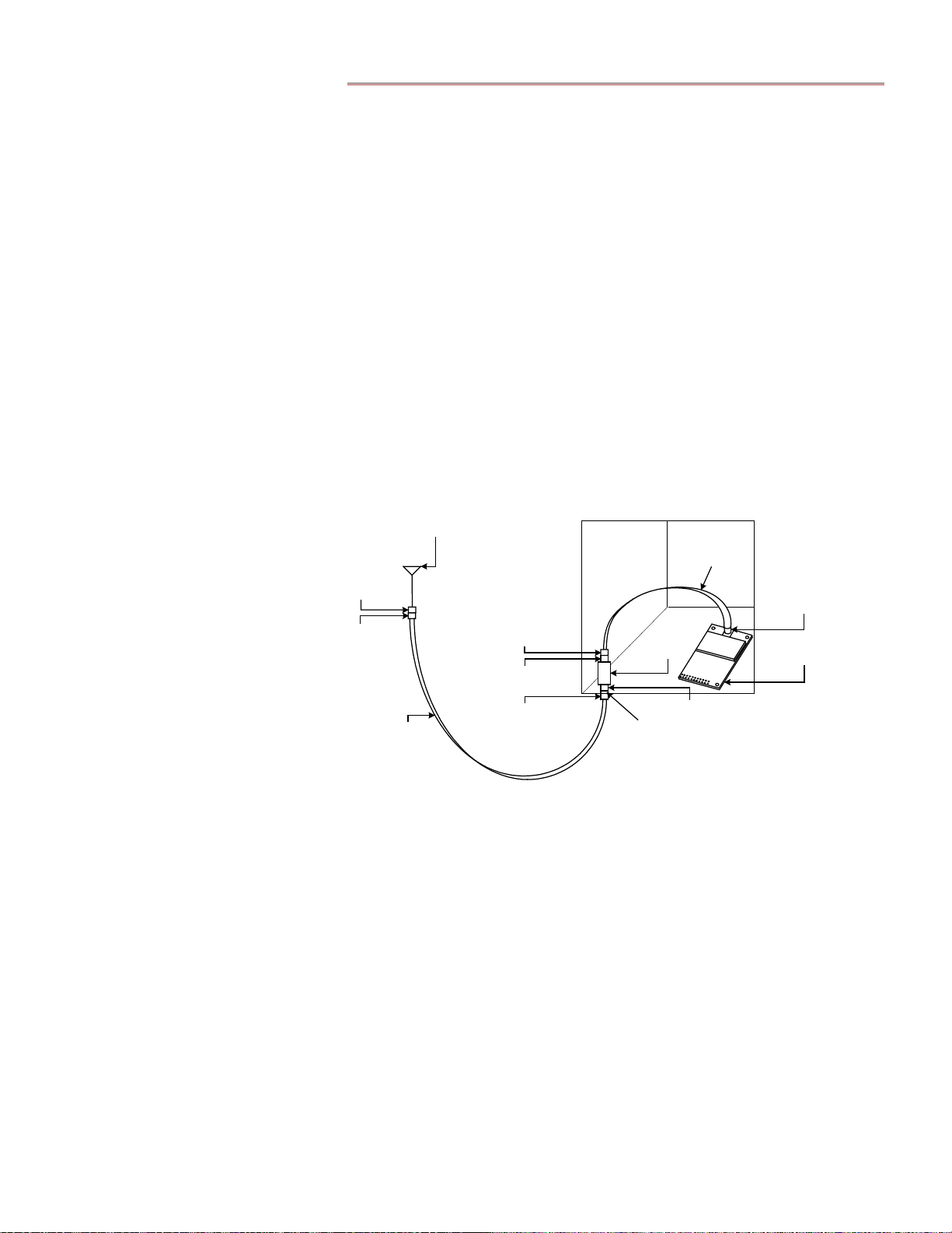
Reverse Polarity SMA Connector
The Reverse Polarity SMA connector is the best choice for remotely mounted antennas such as
those placed on equipment boxes. An example of an RP-SMA connection is a Thunderbird
radio mounted inside a NEMA enclosure for protection from the elements (see Figure 3 below),
with a lightning arrestor used as a bulkhead feed-through connecting to an external coax, which
in turn connects to an antenna mounted on a tower.
Antenna
Female
N-Connector
Male
N-Connector
Good
Low-Loss
Coax
NEMA Box
Male N-Connector
Female N-Connector
Male N-Connector
Gasket
¼" Coax Cable
Lightning
Arrestor
Female N-Connector
RP-SMA
Connector
Thunderbird
Figure 3. NEMA Box Connection
The connection inside the box is usually accomplished via a high-quality ¼" diameter coaxial
cable, like the Times LMR-195 or similar, as these coax choices are easier to route inside a box
than the 0.400" or 0.600" diameter coax products commonly used to run up the side of a tower.
For tighter mounting restrictions, an RP-SMA connection can be extended off the PCB with a
soldered coax pig-tail. This kind of connection would use an RG-316, 0.140" diameter coaxial
cable. The RG-316 has a large attenuation factor, so it should not be more than 12" long.
MMCX Connector
The MMCX connector provides a push-on, snap-action connection designed for a very limited
number of insertions. The MMCX connector is best for miniature coaxes most often seen where
very tight spaces and short runs are involved. Example uses for MMCX connections are mobile
and portable applications. An RP-SMA connector can also be used for those applications where
a screw-on connector is required.
© 2004 Grayhill, Inc., Confidential and Proprietary Page
8

EZCom Thunderbird Radio – Product Guide v0.68
Antennas
Several common antennas have been pre-qualified for use with the Thunderbird RF module,
including high-gain patch antennas for directional links and high-gain, omni-directional antennas
for wide-area coverage.
Only Grayhill-approved antennas and cables may be used with this radio. If none of the
antennas listed in the RF Module Approved Antenna Lists (below) meet your needs, Grayhill
can provide or suggest an antenna solution that will be optimal for your application and will
meet FCC requirements.
For optimal antenna operation, it is important that an antenna have an unobstructed line-of-sight.
Radios with ¼ wave wire antennas soldered to their PCBs and no obstructions in their lines-ofsight work much better than radios with more expensive antennas that have obstructions in their
lines-of-sight. An unobstructed line-of-sight means there is no non-gaseous matter with particles
larger than 0.020" diameter between the antennas. Fog and smoke should not pose a problem.
Note: Plastic generally does not cause line-of-sight problems unless the carbon content of the
plastic is high (carbon is usually added for EMC shielding). Some colorants used in plasticmaking can also pose line-of-sight problems. Metal, stone and anything that absorbs water is
considered an obstruction.
RF Module Approved Antenna Lists
FCC regulations limit the exposure of the human body to RF energy emitted by this transmitter.
The antennas listed below have a defined separation distance from any human body during
normal usage. These limits are very conservative; however, these separation distances are
required to conform to FCC regulations. Smaller separations distances can be achieved, but this
can only be done on a case-by-case basis and are likely to require FCC approval. Contact
Grayhill Engineering for more information.
Table 2.
Note: Especially with high-gain antennas, the antennas need to be positioned at least three feet (one
meter) apart for any two radios to communicate reliably.
When integrated into OEM products, fixed antennas require installation that prevents end users
from replacing them with non-approved antennas. Antennas not listed in Tables 2 and 3 must
be tested to comply with FCC Section 15.247 (emissions) and RF exposure limits.
Antennas with 20 cm. Minimum Separation Distances
Antenn a Type
Yagi Maxrad BMOY8905 9 WL-ANT-Y9A
Yagi LM BYSS-090-09-01 9 WL-ANT-Y9LA
Patch LM
Patch Maxrad MP8068 8 WLHH1434-1
Omni Maxrad MFB9157 7
Omni Maxrad MFB9153 3 WLHH1230-1
PCB Dipole Centurion Revie PRO 0 01HH5222-2
Whip Maxrad MEXE902 -0.5
¼ Wave Integrated
Wire Antenna
!
WARNING: This device has been tested with the antennas listed in Tables 2 and 3 above.
Manufactur
er
Grayhill
Manufacturer
Part Number
BPAS85-090-08-
11SW
Permanent
Antenna Wire
Gain
(dB
d)
8 WL-ANT-P9LA
-3
Grayhill
Part Number
WL-ANT-
MN7A
WL-ANT-
W9MA
WM09STDB-
0003
© 2004 Grayhill, Inc., Confidential and Proprietary Page
9
EZCom Thunderbird Radio – Product Guide v0.68
Mechanical Interface
The Thunderbird was designed to be bolted to a host PCB and has mounting holes for #4 socket
head cap screws for this purpose. You can bolt the radio board itself to a panel or fixture. If you
decide to mount the RF module away from the electrical device to which it connects, plug a
ribbon cable into the main interface connector to bring the signals out. With the right length of
screw standoff, it is possible to capture the ribbon cable connector in such a way that it will not
come off unless the screws holding the PCB to the surface on which it is mounted are removed.
This method secures the cable against vibration.
3.3V CMOS Logic
FOUT
DI (Data In)
Microcontroller
FIN
DI (Data Out)
Thunderbird
Radio
Figure 4. Communications with UART Interfaced Host Devices
Another way to mount the Thunderbird on a host is to connect the module to the Grayhill
interface board via the main interface connector, and then bolt the interface board to the host.
The interface board’s screw holes are larger than those on the Thunderbird PCB, and will
accommodate any standard #4 screw. Use of the interface board also allows for I/O signals to be
brought out on a separate connector from the serial interface. See the Standard Interface Board
section below for more information.
Your RF cabling should be kept as short as practical and secured in such a way that it will not
vibrate and wear the insulation off. To have the cabling pass through the side of a box or case,
use a bulkhead fitting. For fixed systems, the bulkhead fitting should be a lighting arrestor.
Grayhill can provide suitable lightning arrestor kits (Grayhill Part Number WL-ARST-1). The
coax connection to any outside enclosure should be in the bottom of the enclosure to allow for a
drip-loop on the coax.
Note: For proper operation, Thunderbird radios should be placed at a minimum of three feet
(one meter) apart.
RF Module Mechanical Drawings
DXF files supplying mechanical drawings of the EZCom Thunderbird RF module are available
at www.grayhilloem.com. See Figure 15 on page 30 for large-scale mechanical drawings of the
standard Thunderbird radio.
© 2004 Grayhill, Inc., Confidential and Proprietary Page
10
EZCom Thunderbird Radio – Product Guide v0.68
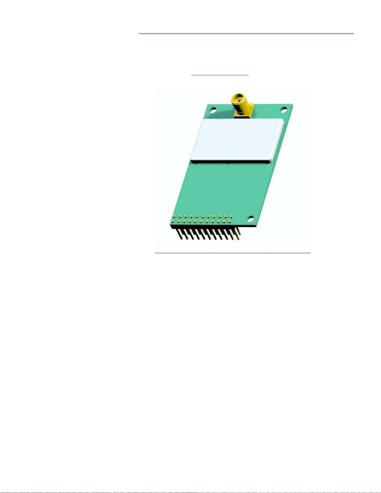
RF Module 3-D Models
To more easily integrate the data radio into other systems, 3-D images of the Thunderbird radio
are provided in STEP format at www.grayhilloem.com. A sample 3-D image of the Thunderbird
radio appears in Figure 5 below.
Standard Interface Board
Grayhill offers an optional interface board (Grayhill Part Number WLYY4097-1) that can
simplify integration of the Thunderbird radio module with RS-232 level equipment and higher
voltage systems. The Grayhill standard interface board provides:
• RS-232 compatible signal levels on a standard female DB-9 connector
• Jumper-selectable DCE or DTE on the serial interface to avoid special cables
• Convenient breakout of the I/O pins to a separate connector for easy I/O usage
• Local voltage regulator capable of up to 19 volt DC input
• TX and RX LEDs for traffic detection
• Hardware reset and command buttons for development use
Setting the J5 Jumper
The jumper at J5 on the standard interface board is factory-set to a DCE configuration (shown on
the left in Figure 6 on page 12) to provide a DCE interface for the usual case where a host PC in
DTE mode exchanges data with the Thunderbird radio.
Figure 5. Thunderbird Radio in 3-D
© 2004 Grayhill, Inc., Confidential and Proprietary Page
11

EZCom Thunderbird Radio – Product Guide v0.68
Under some circumstances, the standard interface board may need to present a DTE interface –
for instance, when the board will be connected to a phone line modem. To have jumper J5 select
a DTE interface, shift its 2-pin shunts into vertical positions, as shown on the right in Figure 6.
J5
1
J5
1
Figure 6. J5 Configured for DCE – J5 Configured for DTE
Connectors and Pinouts
Power Connector
Each Grayhill interface board has a 2.1 mm wide by 3 mm long female barrel connector for
power input. For safety reasons, the polarity of the power connector is positive at the center and
the polarity of its outer shell is negative. Power supplied to the board must be greater than 5V at
300 mA with no more than 100 mVp-p noise.
Mating power connectors can be found at Radio Shack or ordered from Digi-Key (Digi-Key Part
Number 24857-ND). Grayhill offers an AC switching wall-wart power supply (Grayhill Part
Number WL-PWR-9V) to conveniently provide power for this board. Note that the board’s
1 amp, 5 volt regulator can be used to power additional small amounts of 5V equipment.
Serial Connector
Each Grayhill standard interface board provides a standard female DB-9 connector, suitable for
an RS-232 connection to a computer via a standard male/female 9-pin serial cable.
GND
NC
NC
RDSD
12345
7896
NCRTSCTSNC
Figure 7. Female DB-9 Connector with RS-232 Signals
I/O Connector
The I/O connector (see the bottom right corner in Figure 8 below) breaks out the 11 available
I/O pins, each with a matching ground pin. This allows the I/O to be connectorized with a ribbon
or insulation displacement cable.
Interface Board Mechanical Drawings
DXF files containing mechanical drawings of the WLYY4097-1 interface board are available at
www.grayhilloem.com. See Figure 16 on page 31 for large-scale mechanical drawings of the
Grayhill standard interface board.
© 2004 Grayhill, Inc., Confidential and Proprietary Page
12

EZCom Thunderbird Radio – Product Guide v0.68
Interface Board 3-D Models
To make it easier to integrate Grayhill WLYY4097-1 interface boards into other systems, 3-D
images of the board are provided in STEP format at www.grayhilloem.com. A sample 3-D
image of the standard interface board appears in Figure 8 below.
Figure 8. Standard Interface Board in 3-D
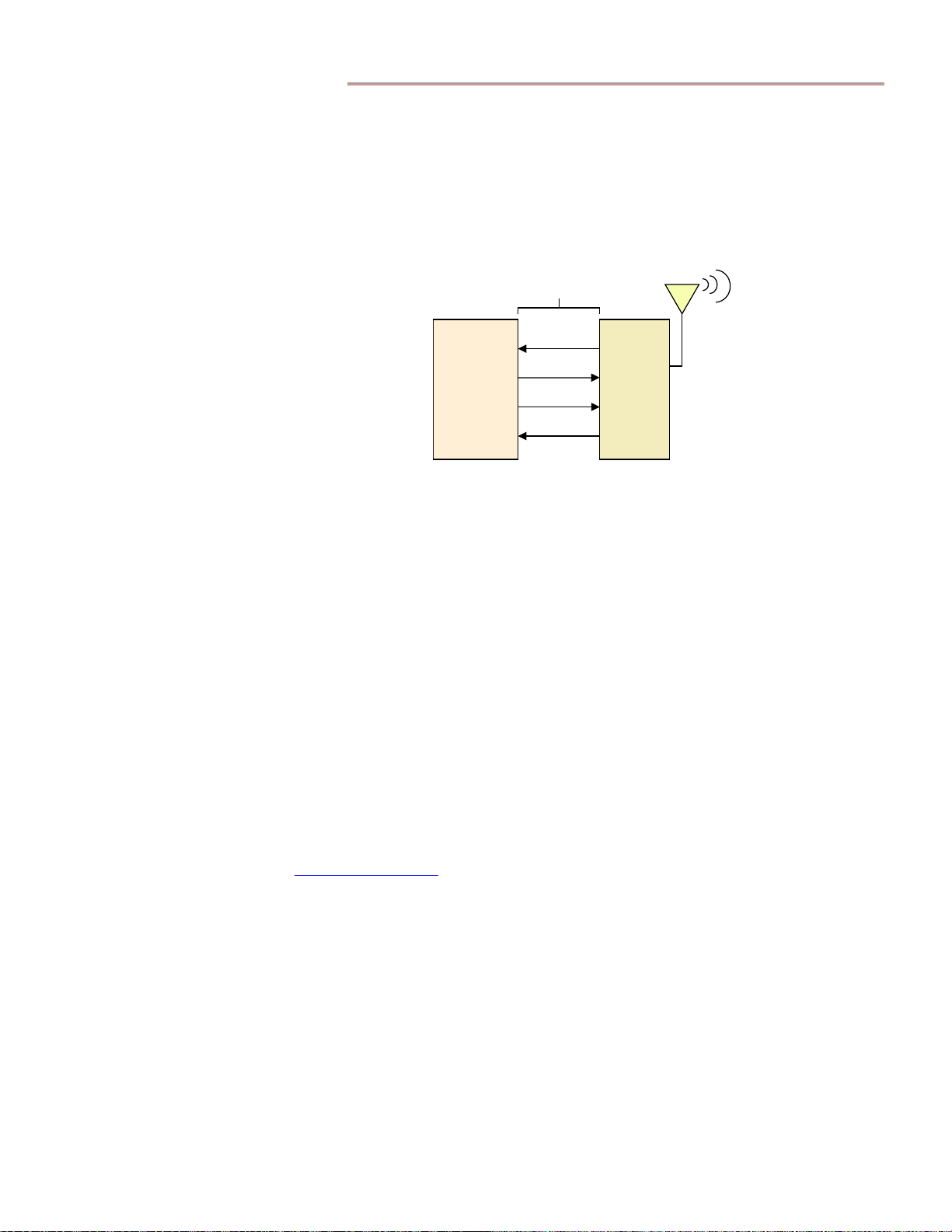
Serial Interface
RS-232 is a single-ended, point-to-point interface, which remains the most common serial
interface outside the industrial market. Since RS-232 data can only traverse distances of up to
50 feet, RS-232 is used less often in industrial applications than RS-485/422 interfaces.
RS-232 Logic
CTS
TX
Standard
PC
Interface
RTS
RX
Figure 9. Communications with RS-232 Interfaced Host Devices
The Grayhill standard interface board provides serial interfacing to the standard Thunderbird
using the RS-232 protocol. While a default serial data rate of 57600 bps is set at the factory,
data rates of 2400, 4800, 9600, 19200, 38400, and 57600 bps are software-selectable.
Configuration section below for more on how to select data rates for the serial interface.
Board
3.3V CMOS Logic
FOUT
DI (Data In)
FIN
DI (Data Out)
Thunderbird
Radio
3
See the
3
On the Thunderbird side, hardware flow control is always enabled. If a host application such as HyperTerminal is set to no flow control, the host application
will simply ignore the Thunderbird’s flow control signals, possibly causing Thunderbird buffers to overflow and drop data. To prevent buffer overflow and
lost data in such a situation, set the serial port to 4800 baud.
© 2004 Grayhill, Inc., Confidential and Proprietary Page
13

Configuration
EZCom Thunderbird Radio – Product Guide v0.68
The advanced addressing and communications settings offered by Thunderbird data radios are
configurable using either AT command mode or binary command mode. By default, all data
received on the Data In pin (Pin A4) is transmitted on the RF channel. Command modes
provide ways to alert a radio that commands – instead of data intended for RF transmission – are
incoming, thus allowing the user to modify various operating parameters. Parameter values
must be saved to the radio’s non-volatile memory (using the ATWR command) or they will be
reset to stored values when the radio is next powered on or reset.
AT Commands
AT command mode can be entered by sending a sequence of three identical break characters to
the unit via the serial connection. By default, the break character is set to 0x2B (“+”), but it can
be changed to a different ASCII character using the ATCC command. All characters that follow
the command sequence are interpreted as AT commands and are not sent as data.
In order for the radio to differentiate AT commands from actual data, a number of timeout
conditions must be met to enter and remain in AT command mode. Timeout conditions are
changed via the commands ATBT, ATAT, and ATCT (or their binary command equivalents).
ATBT and ATAT define “silent” times during which no characters can be sent before and after
(respectively) sending the AT command sequence, and have initial values of 1 second. ATCT
specifies the AT command mode timeout, whose initial value is 20 seconds. For more on these
AT commands, see the Configuration Command Table on page 16.
AT commands are sent in the following format:
AT + 2-character command + space (optional) + parameter (optional) + carriage return
AT command characters are ASCII characters, whose alphabetic characters are case-insensitive.
Parameters are up to four characters long, and are specified as hexadecimal values. A space is
an ASCII character of value 32 decimal (0x20). A carriage return is a character of value 13
decimal (0x0D).
Current parameter settings can be retrieved by sending an AT command without the parameter.
The RF module responds to a valid AT command with “OK,” but responds with “ERROR” if an
AT command is not recognized or if the AT command string format is incorrect.
Example – to send an AT command to change the radio address to 1A0D (hex), enter:
+++
ATDT 1A0D<CR>
ATCN<CR>
where <CR> represents a carriage return.
The ATCN command allows an immediate exit from AT command mode. Otherwise, the radio
automatically returns to data mode when no further valid AT commands have been received
within the AT command timeout period (set by ATCT or its equivalent binary command).
© 2004 Grayhill, Inc., Confidential and Proprietary Page
14

EZCom Thunderbird Radio – Product Guide v0.68
Binary Commands
To send a binary command, “flow control in” (FIN), i.e., Pin A5, needs to be set high by the host
while the command byte is sent to the module. FIN can be set low while parameter values are
sent. If all parameters are received within 0.5 seconds, the command is executed; otherwise, the
radio returns to data mode, ignoring the command.
Binary commands have the following format:
Single-byte command (BIN) + two-byte parameter (optional)
Note: If a parameter is two bytes long, the least significant byte needs to be sent first. If the
parameter is one byte long, a 0x00 byte needs to be sent after the command byte and before the
parameter byte.
Example – to set Sleep Mode to 8 seconds:
Assert FIN to enter binary command mode
Send bytes: 0x01, 0x00, 0x07, 0x08 (ATSM 7 and ATWR as binary commands)
Deassert FIN to exit binary command mode
In binary command mode, the RF module does not respond with a confirmation message unless
it receives a query for the current parameter setting. To send a query for a parameter value, FIN
is asserted while sending a byte containing the value of the corresponding command number
XORed with 0x80. The number of bytes returned to the host is specified in the Configuration
Command Table on page 16.
© 2004 Grayhill, Inc., Confidential and Proprietary Page
15

EZCom Thunderbird Radio – Product Guide v0.68
Table 3.
Configuration Command Table
Thunderbird data radios expect numerical values in hexadecimal.
Description Parameter Values
Binary
CommandATCommand
00 DT Radio Address 0000 to FFFF (0 to 65535) 2 0000
00 – no sleep mode
02 – wake from serial RX
03 – cyclic 0.5 second sleep
01 SM Sleep Mode
02 ST Time before sleep (valid only in RX and Cyclic Modes) 0001 to FFFF (1 to 65535) in 1/10s of seconds 2 0064
03 HT
04 BT Time before AT command sequence 0001 to FFFF (1 to 65535) in 1/10s of seconds 2 000A
05 AT Time after AT command sequence 0001 to FFFF (1 to 65535) in 1/10s of seconds 2 000A
06 CT Timeout from AT command mode 0001 to FFFF (1 to 65535) in 1/10s of seconds 2 00C8
07 FL
08 WR Write all configurable parameters to non-volatile memory None N/A N/A
09 CN Exit from AT command mode immediately None N/A N/A
0A E0 AT command mode character echo off (default) None N/A N/A
0B E1 AT command mode character echo on None N/A N/A
0C LH Beacon duration 00 to FF (0 to 255) in 1/10s of seconds 1 00
0D FH Force beacon on next transmit None N/A N/A
0E RE Restore default configuration values None N/A N/A
0F ER Receive error count
10 GD Receive good count
11 HP Hop Set/Radio Group number 00 to 06 1 00
12 MK Radio Address Mask 0000 to FFFF (0 to 65535) 2 FFFF
13 CC AT command sequence character 20 to 7F (32 to 127) 1 2B
14 VR Firmware version 0000 to FFFF (0.0 to 255.255) 2 N/A
15 BD
16 RT Enable/disable binary command mode access
17 SY Synchronization timer 00 to FF (0 to 255) 1 14
18 SN Subnet ID 00 (default) to 1E 1 00
Time before beacon (time of inactivity on RX pin before a
beacon is used)
Enable/disable serial software flow control. Hardware
flow control (FOUT) is always enabled.
UART baud rate (AT command mode: Issue ATCN
command for new baud rate to take effect; Binary
command mode: Issue 08 command and reboot.)
04 – cyclic 1.0 second sleep
05 – cyclic 2.0 second sleep
06 – cyclic 4.0 second sleep
07 – cyclic 8.0 second sleep
0000 to FFFF (0 to 65535) in 1/10s of seconds
A value of 65535 means no beacon.
0 – Serial software flow control disabled
1 – Serial software flow control enabled
Number of receive packet errors. Value is
reset to 0 on power-up.
Number of good receive packets. Value is
reset to 0 on power-up.
01 – 2400 04 – 19200
02 – 4800 05 - 38400
03 – 9600 06 - 57600
0 – binary command mode access disabled
1 – binary command mode access enabled
# of bytes
Factory
1 00
2 FFFF
1 00
2 0000
2 0000
1 06
1 00
Default
© 2004 Grayhill, Inc., Confidential and Proprietary Page
16

Operation
EZCom Thunderbird Radio – Product Guide v0.68
The EZCom Thunderbird radio operates in half-duplex mode – either transmitting or receiving
data over the air, but not both at the same time. After transmitting RF data, the unit transitions
to a standby operation before it can receive any data presented over the air waves; likewise, after
receiving RF data, the radio moves to standby before it can transmit any data arriving at its serial
port. Table 4 presents radio power mode definitions and current usages.
4
Table 4.
Power Mode Description Current
Standby Mode
Transmit Mode The radio is fully operational and is currently transmitting data. 168 mA
Receive Mode The radio is fully operational and is currently receiving data. 40 mA
Serial Receive
Low-Power
Mode
(Standard
Thunderbird
Only)
Cyclic
Low-Power
Mode
(Standard
Thunderbird
Only)
Pin Sleep Mode
(Standard
Thunderbird
Only)
The radio is fully operational and is currently scanning channels for valid
data.
The radio configured for this Sleep Mode automatically enters this mode
after a user-defined inactivity timeout occurs on both the serial and the RF
channel. When the radio is in this mode, any character received on the
serial channel causes the radio to transition into Transmit Mode.
The radio configured for this Sleep Mode automatically enters this mode
after a user-defined inactivity timeout occurs on both the serial and the RF
channel. The radio remains in this mode for the period of time set for
Cyclic sleep, after which it awakes and starts scanning the hop channels
for data. If no data is detected in one pass through a hop set, the radio
goes back to Cyclic sleep.
When Pin 2 is asserted (high), the radio powers down. 13 mA
Thunderbird Power Modes
Standby Mode
36 mA
18 mA
18 mA,
but 36
mA
for 160
ms
every
cycle
During times of radio activity when the radio is neither transmitting nor receiving, the EZCom
Thunderbird radio goes into Standby Mode. From Standby, the unit can move into:
• Transmit Mode, if data is presented on the serial port
• Receive Mode, if data is presented over the air
• Serial Receive Low-Power Mode
• Cyclic Low-Power Mode
The radio moves from Transmit or Receive Mode into Standby Mode when no data comes in on
the serial or the RF channel (respectively), or when a receive error is detected. Further inactivity
on both channels can result in a move from Standby to the assigned low-power mode.
Transmit Mode
When the first byte of data is received on the UART and moved into the unit’s RF transmit
buffer, the Thunderbird unit moves from Standby to Transmit Mode, taking 2 ms to do so. The
radio can buffer up to 254 characters, but deasserts FOUT flow control when approximately 200
characters occupy the transmit buffer, signaling to the host device to stop sending data.
Note: Although software flow control is available for data incoming on the serial line (using the
ATFL command), hardware flow control is the preferred flow control method. Software flow
control relies on the host’s transmission of the control characters 0x11 and 0x13 (the decimal
numbers 17 and 19) over the data lines. When serial software flow control is on, if the radio
4
The current usages shown in Table 4 are based on tests using a standard Thunderbird mounted on a standard interface board.
© 2004 Grayhill, Inc., Confidential and Proprietary Page
17

EZCom Thunderbird Radio – Product Guide v0.68
receives any legitimate data byte with the same value as one of the software flow control
characters during the course of regular data transmission from the host to the radio, the radio will
assume these are flow control characters, not data bytes, and transmission will stall. When the
host is transmitting strictly text to the radio, however, software flow control may work just as
well as hardware flow control.
The Thunderbird radio does not use a framed protocol to transmit data, but rather relies on a
more transparent-mode functionality. The radio makes decisions to transmit data based on one
of two factors – whether its buffer is full, or if it is not full, if there is some data in the buffer and
no new data has arrived for a set timeout period.
In Transmit Mode, the radio packetizes the data in its transmit buffer into 35-byte packets. For
each packet, the unit computes a 16-bit CRC and attaches it to the end of the packet before
transmitting it over the air. Once all packetized data has been transmitted and the RF transmit
buffer is empty, the radio returns to Standby Mode.
Receive Mode
When a Thunderbird radio detects data incoming over the RF channel, it transitions to Receive
Mode. Once in Receive Mode, the radio processes the received data packets and sends data out
its serial port. The radio then stays in Receive Mode and does not return to Standby Mode until
it detects no more incoming RF data or it encounters an error in a packet’s CRC – in the latter
case, it discards the packet and does not transmit data out its serial port. If serial data was stored
in the radio’s RF transmit buffer during the time it was in Receive Mode, once the Thunderbird
returns to Standby Mode it processes the data and transmits it.
In order for Thunderbird radios to communicate properly with other Thunderbird units, they
need to synchronize with each other on a regular basis to ensure that all units traverse the hop
sequence at the same time. Synchronization is achieved during transmission by using a
synchronization header that precedes the packet payload.
The synchronization header, which takes 180 ms (milliseconds) to send, is considerably longer
than the regular Thunderbird header, which only takes 3 ms. After synchronization, Thunderbird
radios use the shorter header until synchronization times out. The next unit that transmits data
will transmit a synchronization header again to resynchronize with the other units. Note that the
synchronization header may cause individual data bytes to be received as much as 200 ms apart.
See Figure 14 in Appendix C for more information.
To reduce average latency time – the time that elapses between the transmitter’s reception of
data in its serial port and the receiver’s transmission of data out its serial port – the integrator can
vary the synchronization timeout setting (via the ATSY command or its binary equivalent).
Depending on network settings, any Thunderbird radio within range of any other Thunderbird
radio may receive any transmission that is valid, but may or may not send the received data out
its serial port, depending on packet address field values. See the Networking section below for a
description of the built-in support for point-to-point and point-to-multipoint networking.
Note: Delivery of data packets is not guaranteed, no notification is sent when packets are
dropped, and no retransmission of dropped packets is attempted. It is assumed that retries are
handled outside of the Thunderbird radio as in a multi-drop, parallel-wired network.
Low-Power Modes
The Thunderbird radio functions as a transceiver only when it is completely powered up; when it
is in one of its low-power modes, it will neither transmit nor receive data until first returning to
Standby Mode. The low-power (or sleep) modes
radio in low-power or battery-operating environments. The Thunderbird initially has no sleep
5
described here make it possible to use the
5
All low-power modes are applicable only for the standard Thunderbird module.
© 2004 Grayhill, Inc., Confidential and Proprietary Page
18

EZCom Thunderbird Radio – Product Guide v0.68
mode enabled, but the system integrator can assign it a Sleep Mode setting by specifying either
Serial Receive or Cyclic Low-Power Mode using the ATSM command or its binary equivalent.
When a low-power mode is configured for a radio, the time interval of inactivity before the radio
moves into the assigned low-power mode can also be modified using the ATST command or its
binary equivalent. The timeout setting specifies a period of time during which the radio receives
no data either over the air or at its serial port.
Serial Receive Low-Power Mode
A Thunderbird radio with Serial Receive Low-Power Mode configured as its Sleep Mode goes
to sleep when no data has come in either over the air or over the serial line from its host for the
timeout period specified by the ATST command. When a radio so configured sleeps, it will
wake up whenever data from its host arrives at its serial port, but not when RF data is incoming
over the air waves. Thus, the integrator should assign this low-power mode only to a radio
whose primary function is to initiate RF communication. In the following section, such a unit is
referred to as the RF initiator.
Cyclic Low-Power Mode
When a radio is in Cyclic sleep, it will not listen for data arriving at its serial port. Instead, each
time its assigned sleep period ends, the radio wakes up and scans all RF channels for incoming
data packets. If no RF data is found, it returns to Cyclic sleep. If RF data is detected, however,
the radio stays powered up, transitions into Receive Mode, and operates normally until inactivity
causes a transition back to Cyclic sleep.
While a unit is in a Cyclic low-power mode, its FIN pin is deasserted so it cannot receive data
over the serial line until it is woken up by a beacon arriving over the air. Thus, the integrator
should assign this low-power mode only to a radio whose primary function is to respond to RF
communication. This kind of unit is referred to here as the RF responder.
An RF initiator with a beacon timeout set to the same value as the ATST value of its responder
will go to Beacon Mode at about the same time that the RF responder moves to Cyclic sleep.
The next time the initiator sends a packet, it transmits a beacon which must be long enough for it
to be detected when the responder next monitors the channel, thus enabling the responder to
power up and receive the data packets that follow the beacon.
If an RF initiator is forced to send a beacon – either because an ATFH command was issued or
because of an inactivity timeout (set by ATHT or its binary equivalent) – it will do so
immediately prior to the data portion. The beacon duration needs to be long enough to
successfully wake up the radio(s) in Cyclic sleep. For example, if an RF responder is set to
wake up every four seconds and check for a beacon, the initiator must send a beacon at least four
seconds long in order to provide enough time for the responder to detect the beacon. To ensure
reception of all packets, packet beacon length must be set via ATLH or its binary equivalent to
match the Cyclic power-up time (which is the time spent in Cyclic sleep).
Pin Sleep Mode
Pin A2 (Power Down) on the Thunderbird’s 22-pin connector is high by default due to a 10K Ω
pull-up resistor on the Thunderbird PCB. Pin A2 must be tied to ground for the radio to power
on. The standard interface board has a fixed pull-down to ensure the radio is powered on when
connected to the interface board. When Pin A2 is asserted (high), the onboard voltage regulator
turns off, and the radio powers down. Pin Sleep Mode, where the entire radio is powered off,
provides the lowest power consumption of all low-power modes. The radio takes 20 ms to move
from Pin Sleep Mode to Standby Mode.
Note: In the Cyclic and Pin Sleep Modes, the FOUT pin (Pin A1) is deasserted (high), signaling
that the radio is in a low-power mode and that data should not be sent to the radio. The
TX/PWR pin (Pin A8) is also deasserted (low) while the radio is in Pin Sleep Mode.
© 2004 Grayhill, Inc., Confidential and Proprietary Page
19

Networking
EZCom Thunderbird Radio – Product Guide v0.68
In its initial, factory-set state, the EZCom Thunderbird radio transmits data that can be received
over the air and output on serial channels by other Thunderbird radios in their default states.
This default broadcast mode of operation, in which every in-range radio node can successfully
receive and process every transmission, allows the design of a system that provides for all
networking tasks – addressing, error checking, acknowledgements and retries – behind the radio
link, as if the nodes were attached to a wired, multi-drop bus.
However, the default networking settings do not provide network security. They do not prevent
reception of wireless network communications by radios on nearby networks owned by other
businesses also using Thunderbird RF technology. Further, using the default settings can result
in interference and cross talk, and does not provide the isolation needed for data exchanges by
radio pairs or radios in subnetworks operating within close proximity of each other.
To ensure security and isolation, system integrators can use the radio’s multiple types of network
addresses to establish radio networks, subnetworks, radio groups and point-to-point links.
Thunderbird radios use the following network parameters:
• Vendor Identification (VID) Numbers
• Subnet IDs
• Radio Group Numbers
• Radio Addresses (RADs) and Radio Address (RAD) Masks
Vendor Identification Numbers
In the interests of network security, a system integrator can request a Vendor Identification
(VID) number to be programmed into multiple EZCom Thunderbird radios at the factory.
Essentially an identifier for the entire network domain of a business, the VID number is stored in
permanent memory and can only be modified at the factory. Contact Grayhill sales for a special
part number with which to order Thunderbird radios programmed with a unique Vendor ID.
Since only radios with matching VID numbers can intercommunicate, VIDs ensure that radios in
one domain will be unable to exchange data with those in another. Note, however, that the
assignment of unique VIDs to different radio networks does not guarantee a total absence of
interference if other radio networks are operating in the same vicinity.
Subnet IDs
The system integrator can facilitate networking within a VID domain by establishing multiple
subdomains using the Subnet ID configuration command. All radios may possess the same VID,
but radios assigned one Subnet ID cannot transmit or receive data to or from radios assigned
other Subnet IDs. Even though the creation of radio subnetworks
between radios to those radios on a subnet, it may only somewhat minimize interference.
To create a subnetwork within a VID domain, the integrator configures the same Subnet ID
parameter value for all radios connected to host computers that belong to a subdomain. Up to
31 subnetworks can be established using the ATSN configuration command or its binary
command equivalent.
6
limits communication
Radio Group Numbers
A radio network or subnetwork can be further broken down into radio groups by assigning the
same Radio Group parameter value to all radios in a functional group of data radios. Using the
ATHP command or its binary equivalent to set a parameter value for a radio’s Radio Group, one
of seven possible pseudo-random frequency-hopping sequences is configured for a radio.
6
Establishment of subnetworks is optional.
7
All Thunderbird radios initially operate using the factory-set, default hop sequence.
© 2004 Grayhill, Inc., Confidential and Proprietary Page
7
20

EZCom Thunderbird Radio – Product Guide v0.68
Only radios in the same VID, subnet, and radio group can intercommunicate. Thus, when radios
share the same VID and subnet but belong to different radio groups, multiple radio pairs can
operate in close proximity, causing each other minimal interference in doing so.
However, even with radios assigned different hop sequences (that is, different Radio Group
parameter values), there is still the possibility that channels will overlap. In the event that
transmissions from radios in different groups collide on a channel, the collision is resolved by
the next hop, since transmissions from radios belonging to different groups follow different
hopping sequences and will jump to separate channels.
While it is possible, by establishing 31 subnets and 7 radio groups in each subnet, to subdivide a
Thunderbird radio network into 217 different “networks,” this does not mean there are 217
possible hop sequences. A fully specified network (see Figure 10 below) would instead be
composed of 31 separate subnetworks, each of which uses the same seven hop sequences.
8
Radio Addresses
To achieve point-to-point communication, each radio is assigned a 16-bit Radio Address (RAD).
When a transmitting radio sends a packet out over the air waves, the transmitting radio’s RAD is
encoded into that packet. Every Thunderbird radio comes with a default RAD of zero. Using
the ATDT command or its binary equivalent, the system integrator can configure one of 65535
possible hexadecimal RAD values for a radio. Note that, unlike wired networking, Thunderbird
network nodes do not require unique network addresses; indeed, the system integrator must
think in terms of assigning duplicate addresses to provide for communication between radios.
To provide an example of RAD use in a Thunderbird wireless network, say that a Radio Group
contains, among others, three RF modules that we shall call Radios A, B, and C. Radios A and
B are assigned the same RAD, but Radio C is assigned a different RAD. When Radio A
transmits data over the air waves, both Radios B and C receive the data, but only Radio B sends
data out its serial port. Radio C discards the packets it receives from Radio A, since the RAD
specified in the packets does not match its own RAD. Radio C listens to the entire transmission,
however, in order to avoid sending a transmission of its own during a transmission of data with a
different RAD, and thus helps to maintain overall network synchronization.
RADIO GROUP 1
RADIO GROUP 3
RADIO GROUP 5
RADIO GROUP 7
RADIO GROUP 6
VID
RADIO GROUP 1
RADIO GROUP 3
RADIO GROUP 5
RADIO GROUP 2
RADIO GROUP 4
SUBNET 4
SUBNET 5
SUBNET 6 ...
RADIO GROUP 7
RADIO GROUP 6
RADIO SUBGROUP –
SAME ADDRESS
RADIO SUBGROUP –
SAME ADDRESS
RADIO SUBGROUP –
SAME ADDRESS
RADIO SUBGROUP –
SAME ADDRESS
RADIO SUBGROUP –
SAME ADDRESS
RADIO SUBGROUP –
SAME ADDRESS
RADIO GROUP 2
RADIO GROUP 4
SUBNET 1
SUBNET 2
SUBNET 3
Figure 10. Thunderbird Radio Network Structure
With the addition of the radio address, a system integrator can implement a complete networking
hierarchy, enabling communications ranging from broadcasts to all radios in the same VID,
subnet and radio group, to highly specific transmissions between the only two radios on the
network that share the same VID, subnet ID, radio group number, and radio address.
8
Network designers may opt to forego establishing subnets for small networks, and only use radio groups/hop sequences to differentiate between network
node functions. In even smaller networks, all radios may exchange data using just one hop sequence, and radio intercommunication may be limited by the use
of different radio addresses.
© 2004 Grayhill, Inc., Confidential and Proprietary Page
21

EZCom Thunderbird Radio – Product Guide v0.68
Radio Address Masks
The Radio Address Mask (RAD mask), set using ATMK or its equivalent binary command, also
facilitates networking within a radio group. The RAD mask, which is the same length as the
RAD (16 bits), is set to the value 0xFFFF at the factory.
During packet reception, any bits set in the RAD mask of the receiver are logically ANDed with
the transmitting radio’s RAD, which was sent as part of the packet. The result is compared to
the receiving radio’s RAD, and only when there is a match is the packet received. Modification
of the value of the RAD mask to such variations as 0x000F, 0x00F0, 0x0F00, and 0xF000
allows broadcasts to subsets of radios in the same VID, subnet, and radio group.
Using the EZCom Thunderbird Evaluation Kit
The RF communications that can be accomplished using the Evaluation Kit demonstrate how
easy it is to operate Thunderbird radios. Simply follow the instructions below to assemble
evaluation kit contents, configure two radio connections, and perform over-the-air data transfer
tests between the two radios.
Evaluation Kit Contents
2 EZCom Thunderbird OEM RF Modules
2 Standard Interface Boards
2 DB-9 Cables
2 AC Adapters
2 Whip Antennas
1 Product CD containing the TRC.TXT test file and the product guide PDF
Evaluation Test Requirements
To use the evaluation kit to test the data radio using an RS-232 serial interface, you’ll need two
computers – each with an available comm port, and each running any operating system.
Assembly Instructions
For a finished assembly, refer to the picture in Figure 11 on page 23.
1. Connect each RF module to one of the interface boards by fitting each module’s 22-pin
connector into each interface board’s female headers.
2. Install a whip antenna on each RF module’s antenna connector.
For best results, position the radios at least three feet (one meter) apart during testing.
3. Insert the male connector on each DB-9 cable into the female DB-9 connector on each of
the interface boards.
4. Attach each DB-9 cable’s female connector to an available comm port on each computer.
5. Plug an AC power supply into each of the interface boards, then into a power outlet.
The green LED on each interface board illuminates, indicating the boards are receiving
power.
© 2004 Grayhill, Inc., Confidential and Proprietary Page
22

EZCom Thunderbird Radio – Product Guide v0.68
Figure 11. Assembled Evaluation Kit
Configuring the Data Connections
Note: When using a telnet program other than HyperTerminal, the instructions below can still be used as a
general guide.
1. Start up HyperTerminal on each computer by selecting Start | Programs | Accessories |
Communications | HyperTerminal.
2. In each computer’s Connection Description dialog box, choose a name and an icon for the
test connection.
3. In each computer’s Connect To dialog (see Figure 12), select the comm port to which the
radio is connected in the Connect using field. (The other fields in the box dim.) Click OK.
Figure 12. Connect To Dialog Box
4. In the COM Properties dialog (see Figure 13), set the following:
• Bits per second – 57600
• Data bits – 8
• Parity – None
• Stop bits – 1
• Flow Control – Hardware
Click OK.
© 2004 Grayhill, Inc., Confidential and Proprietary Page
23

EZCom Thunderbird Radio – Product Guide v0.68
Figure 13. Com Properties Dialog Box
Radio-computer connections are now configured and ready for the data communications test.
Testing RF Data Communications
1. Select one of the HyperTerminal windows and type a message.
The text you type is immediately transferred over the air and appears only in the remote
HyperTerminal window.
2. Select the other HyperTerminal window and type a message.
The text you type appears only in the remote HyperTerminal window.
3. Insert the evaluation kit CD into one computer’s CD drive (called D: for our purposes) and
initiate a file transfer over the air by doing the following:
a) Select Send File on the HyperTerminal Transfer menu (or right-click in the
HyperTerminal window and select Send File) to display the Send File dialog box.
b) In the Send File box, select Filename: D:\TRC.TXT and Protocol: Ymodem.
c) Click Send.
4. Set up the other computer to receive the file transfer by doing the following:
a) Select Receive File from the Transfer menu (or right-click in the HyperTerminal
window and select Receive File) to display the Receive File dialog box.
b) In the Receive File box, select a folder in which to place the received file and
select Protocol: Ymodem.
c) Click Receive.
The file transfer begins. The text of the TRC.TXT file appears in the other computer’s
HyperTerminal window.
5. After the completion of this and subsequent file transfers, examine the transferred
TRC.TXT text to see if any characters were lost or corrupted.
6. Transfer the file more times. Reverse the direction of the file transfer. Try data transfers
with Xmodem selected on each computer.
7. Perform range testing by placing the two computers at increasing distances from each other.
© 2004 Grayhill, Inc., Confidential and Proprietary Page
24

EZCom Thunderbird Radio – Product Guide v0.68
Troubleshooting the Evaluation Test
1. Can’t find the HyperTerminal program (or other telnet program) on your computer?
• Search your hard drive for HyperTrm.exe (or the other telnet program you will use).
• Go to www.hilgraeve.com for a free version of HyperTerminal. For TELIX, see
www.mcc.com.au/web/telixdos.htm. For Kermit, see www.columbia.edu/kermit/.
2. Power LED doesn’t illuminate when the Thunderbird powers on?
• Remove and reconnect the AC adapter to the interface board.
3. Can’t connect to the comm port, or data communications not working?
• Try choosing another comm port by selecting Properties under the File menu.
• If necessary, validate the operation of the two computers’ comm ports by using a null
modem cable (cross RX and TX).
4. Characters transmitted over the air getting scrambled or lost?
• Verify that both host computers’ comm ports are set to the Thunderbird’s serial data
transfer rate.
© 2004 Grayhill, Inc., Confidential and Proprietary Page
25

EZCom Thunderbird Radio – Product Guide v0.68
Appendix A. EZCom Thunderbird CF
EZCom Thunderbird data radio functionality is also available in a Compact Flash (CF) card to
facilitate networking with handheld personal digital assistants (PDAs).
CF Interface
The Thunderbird CF’s Compact Flash interface replaces the standard Thunderbird’s 100 mil
interface header and is designed to fit standard Compact Flash I/O ports.
RF Connector and Antennas
The MMCX antenna connector at the top of the Thunderbird CF card allows installation of an
antenna approved by Grayhill (see Table 5 below). The MMCX connector provides a push-on,
snap-action connection designed for a limited number of antenna insertions.
Table 5.
Thunderbird CF Approved Antenna List
Antenna Type Manufacturer
Whip Maxrad MEXE902 -0.5
Note: To obtain approval of other antennas for use with the Thunderbird CF, contact Grayhill. This radio
device may only be used with antennas provided by Grayhill or verified by Grayhill Engineering to comply
with FCC regulations.
Manufacturer
Part Number
Gain
(dBd)
Grayhill
Part Number
WL-ANT-
W9MA
Min. Separation
Distance
5 cm
PDA Support
The Thunderbird CF’s driver supports Windows CE 3.0 for the Pocket PC. The CF card permits
data exchange between its host PDA and other PDAs equipped with Thunderbird CF cards, as
well as desktops, laptops, and any other host devices connected to standard Thunderbird radios.
Note that receiving host devices may be running any operating system.
The Thunderbird CF is set at the factory to run exclusively at a serial baud rate of 57600 bps.
The CF card is configurable for ports COM1-COM4, but its serial port is factory-set to COM2
on the handheld device. Should changes to the serial baud rate or COM port assignment be
needed, contact Grayhill. The Thunderbird CF has no low-power modes, but powers down
when the COM port on the CE device closes. If software is needed to support integration of the
Thunderbird CF into a handheld device, contact Grayhill.
Configuring a Terminal Connection
Note: The handheld device’s CE driver must be installed before you insert the CF card into the device.
To set up a terminal connection for the EZCom Thunderbird CF:
1. Insert the Thunderbird CF into the PDA’s Compact Flash slot.
2. On the PDA, select the Start menu and then Settings.
3. Click the Connections tab on the bottom of the Settings dialog box.
4. In the Connections dialog, select Modem and then New Connection.
5. In the Enter a name for the connection field, enter the connection name, e.g., Thunderbird.
6. Choose Grayhill-TBird on the Select a modem drop-down menu.
7. Select 57600 for the Baud Rate. (Or select the custom baud rate you have requested.)
© 2004 Grayhill, Inc., Confidential and Proprietary Page
26

EZCom Thunderbird Radio – Product Guide v0.68
8. Click the Advanced… button.
9. Verify that the following Connection preferences are set:
• Data Bits – 8
• Parity – None
• Stop Bits – 1
• Flow Control – Hardware
10. On the bottom of the Advanced dialog under Terminal settings, select the Use terminal
before connecting and the Enter dialing commands manually checkboxes.
11. Click OK.
12. In the Make New Connection dialog, select Next.
13. In the dialog box that follows, deselect the Cancel call if not connected within and the Wait
for dial tone checkboxes.
14. Click Finish.
The Thunderbird CF card is now configured for a terminal connection.
Opening a Terminal Connection
To open a terminal connection:
1. On the PDA, select the Start menu and then Programs.
2. Click Connections.
3. In the Connections dialog, select the configured connection, e.g., Thunderbird.
4. In the next dialog box, click Connect.
If the Thunderbird CF card was properly installed, the Manual Dial Terminal window appears.
The Manual Dial Terminal window provides the same functionality that HyperTerminal or
another telnet program provides to the standard Thunderbird unit.
Configuring the Thunderbird CF
Use the Manual Dial Terminal window to configure the Thunderbird CF. Consult the
Configuration section on pages 14-16 for details on using AT or binary command mode to send
configuration commands to the Thunderbird CF.
Testing Thunderbird CF Data Transfer
Once the configuration of the Thunderbird CF and its connection is complete, the user can verify
its operation and test over-the-air data transfer by inputting a message in the data-mode Manual
Dial Terminal window on the PDA. The text you enter should appear in the window connected
to another Thunderbird or Thunderbird CF unit.
© 2004 Grayhill, Inc., Confidential and Proprietary Page
27

Appendix B. Specifications
Table 6.
Specification Thunderbird RF Module Thunderbird CF Card
Performance
Indoor/Urban Range Up to 1800 feet Up to 1800 feet
Outdoor LOS Range
RF Data Rate Up to 19200 bps Up to 19200 bps
Transmit Power Output 160 mW (22 ± 2 dBm) 160 mW (22 ± 2 dBm)
Receiver Sensitivity 10-6 BER, -105 dBm 10-6 BER, -105 dBm
General
Frequency
Spread Spectrum
Channel Capacity
Network Topology
Subnetwork Capacity Up to 31 Subnetworks Up to 31 Subnetworks
Serial Data Interface RS-232 CF Type 2 Extension
I/O Data Rate
Power Requirements
Supply Voltage 4.5-15 VDC ± 5% V regulated 3.3 VDC ± 5% V regulated
Transmit Current 160 mA N/A
Receive Current 30 mA N/A
Low-Power Current ≤ 10 mA N/A
Physical Properties
Dimensions
Weight 0.75 oz. 0.70 oz.
Connector
Operating Temperature -40° to 70° -40° to 70°
Storage Temperature -40° to 85° -40° to 85°
Antenna
Integrated Wire (optional)
Connector (optional) Reverse Polarity SMA or MMCX MMCX
Impedance 50 ohms unbalanced 50 ohms unbalanced
Certification
FCC Part 15.247 NMAWM09STDB0001 NMAWM09STDB0002
Industry Canada (IC) Pending Pending
EZCom Thunderbird Radio Specifications
Up to 8 miles with dipole antenna
Up to 24 miles w/high-gain antenna
902-928 MHz, standard
902-921 MHz, anti-pager model
Frequency Hopping,
Wideband FM Modulator
7 hop sequences share 20-27
frequencies.
Peer-to-Peer, Point-to-Multipoint, Pointto-Point, Multi-Drop
Software selectable from 2400 bps –
57600 bps
1.5" x 2.5" x 0.17" (module only)
Height depends on antenna
connection method.
2 x 11, 0.1" pitch male Berg-type
header with 0.025" square pins
¼ wave monopole, 3" length,
-3 dBd gain
EZCom Thunderbird Radio – Product Guide v0.68
Up to 8 miles with dipole antenna
902-928 MHz
Frequency Hopping,
Wideband FM Modulator
7 hop sequences share 20-27
frequencies.
Peer-to-Peer, Point-to-Multipoint,
Point-to-Point, Multi-Drop
Factory-set to 57600 bps. Custom
baud rate can be requested.
N/A
Compact Flash
N/A
© 2004 Grayhill, Inc., Confidential and Proprietary Page
28

EZCom Thunderbird Radio – Product Guide v0.68
Appendix C. Data Packet Timing Diagrams
Transmission
s
1
m
Delay
Unit hops to
transmission
channel
Synchronization Hop Slot - 202 ms
18 ms
packet size)
(depending on
Between 1 and
Between 3 and 20 ms
(depending on packet size)
180 ms
Transmits payload header &
Transmitter Idle
data
each other)
Transmission
complete
First byte is
transmitted via
RF channel
Between 1 and
1
Between 1 and
18 ms
(depending on
Between 3 and 20 ms
(depending on packet size)
3 ms
s
m
18 ms
(depending on
packet size)
Transmits payload header &
Short TX
Transmission
Delay
packet size)
Transmitter Idle
data
Header
Transmitter Idle
Transmission
First byte is
Unit hops to
Transmission
complete
transmitted via
transmission
complete
RF channel
channel
data
Figure 14. Data Packets with Synchronization and Regular Headers
Between 3 and 20 ms
(depending on packet size)
Regular Hop Slot - 25 ms
Transmit cycle (synchronization header)
Synchronization Header (necessary for Thunderbird radios to resynchronize with
Transmission
s
1
m
Delay
s
1
m
Unit hops to
transmission channel
First data byte enters
Thunderbird UART
Transmit cycle (regular header)
3 ms
1
m
Transmission
s
Transmits payload header &
Short TX
Delay
First byte is
transmitted via
RF channel
Header
Unit hops to
transmission
channel
© 2004 Grayhill, Inc., Confidential and Proprietary Page
29

Appendix D. Mechanical Drawings
EZCom Thunderbird Radio – Product Guide v0.68
Figure 15. Thunderbird RF Module Mechanical Drawings
© 2004 Grayhill, Inc., Confidential and Proprietary Page
30

EZCom Thunderbird Radio – Product Guide v0.68
Figure 16. Standard Interface Board Mechanical Drawings
© 2004 Grayhill, Inc., Confidential and Proprietary Page
31

Appendix E. Agency Certification
The EZCom Thunderbird radio complies with Title 47, Part 15, Section 247 of the FCC Rules
for radio communication devices.
FCC Approved (USA)
FCC IDs: Standard Thunderbird – NMAWM09STDB0001
Thunderbird CF – NMAWM09STDB0002
Devices that embed EZCom Thunderbird radios can inherit Grayhill’s FCC certification,
provided that 1) the FCC label shown in Figure 17 below is reproduced and placed on the
outside of the final product and 2) only approved antennas are used in the final product.
Industry Canada Certified #: (Pending)
FCC Notices
EZCom Thunderbird Radio – Product Guide v0.68
This radio equipment has been tested and found to comply with the limits for a Class B digital
device, pursuant to Part 15 of the FCC Rules. These limits are designed to provide reasonable
protection against harmful interference in a residential installation. This equipment generates,
uses, and can radiate radio frequency energy and, if not installed and used in accordance with the
instructions, may cause harmful interference to radio communications.
However, there is no guarantee that interference will not occur in a particular installation. If this
equipment does cause harmful interference to radio or television reception, which can be
determined by turning the equipment off and on, the user is encouraged to try to correct the
interference by one or more of the following measures:
• Reorient or relocate the receiving antenna.
• Increase the separation between the transmitter and the receiver.
• Connect the transmitter into an outlet on a circuit different from that to which the
receiver is connected.
• Consult the dealer or ask an experienced radio/TV technician for help.
FCC RF Exposure Certification
The Thunderbird radio is approved by the FCC for fixed and mobile (not portable) applications.
If a minimum separation distance of 2 meters is maintained during operation between an antenna
with a gain ≥ 6 dBi and nearby persons, the application is considered a fixed base station
application. If a minimum separation distance of 20 cm (8") is maintained between an antenna
with a gain < 6 dBi from nearby persons, the application is considered a mobile application.
To comply with the FCC’s RF exposure requirements, the Thunderbird radio may be used only
with approved antennas that have been tested with the radio. A minimum separation distance of
20 cm from the antenna to any nearby person must be maintained. The system integrator must
also include a CAUTION statement in the final product manual, informing users of the
requirement to maintain a minimum 20 cm separation distance between the antenna and any
nearby person.
If the Thunderbird is installed into a final product that is classified as a portable device per FCC
Section 2.1093 (where less than a 20 cm separation distance exists between the antenna and any
nearby person), the system integrator can use one of the limited number of lower gain antennas
© 2004 Grayhill, Inc., Confidential and Proprietary Page
32

EZCom Thunderbird Radio – Product Guide v0.68
that have been tested with and approved for the Thunderbird, and that have a 5 cm separation
distance. Thunderbird can be used, as is, in portable applications, but only with these lower gain
antennas and only if the 5 cm distance can be maintained. Other antennas and smaller separation
distances are possible, but will likely require testing to meet FCC rules.
FCC Qualifications
The EZCom Thunderbird radio has been certified by the FCC for integration into products
without any further certification (as per FCC section 2.1091). Changes or modifications not
expressly approved by Grayhill could void the user’s authority to operate the OEM equipment as
well as the warranty.
OEM system integrators must verify that their final product complies with unintentional radiator
limits (FCC section 15.107 and 15.109) before declaring final product compliance to Part 15 of
the FCC Rules.
OEM Labeling Requirements
It is an FCC requirement that the FCC ID of this OEM radio device be clearly visible on the
outside of any final product in which it is installed. System integrators using the OEM
Thunderbird radio must place the label shown in Figure 17 below on the outside of the final
product. A high resolution PDF of this label is available at www.grayhilloem.com.
Figure 17. Required FCC Label for OEM Products
© 2004 Grayhill, Inc., Confidential and Proprietary Page
33

EZCom Thunderbird Radio – Product Guide v0.68
© 2004 Grayhill, Inc., Confidential and Proprietary Page
34
 Loading...