

Page 1
Special Function Rotary Switches
DIM. A
500
015
DIM. A
046 (1,17)
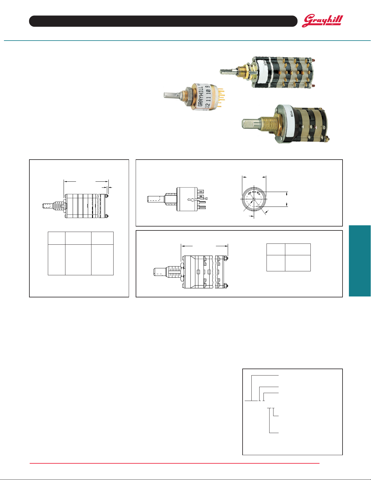
SERIES 08,09,42,44,50
Spring Return
FEATURES
• Hold-To-Test, Hold-To-Calibrate,
And Other Momentary Applications
• Choice of Configurations, Ratings,
Styles and Circuitry
• 10,000 Cycles of Operation
DESCRIPTION
A spring return rotary switch has 1 or more momentary positions. Maintaining contact at momentary
positions requires rotational force. Releasing the force allows the mechanism to return the contact
to a normal, or detent, position.
DIMENSIONS
Series 08 & 09
+ .046 (1,17)
–.020 (0,51)
DIM. B REF.
STUD PROJECTION
Series 50
Equivalent to Series 50 Standard Switches
COMMON
.
± .
(12,7 ± 0,38)
DIA.
36°
± 3°
.320 ± .015 (8,13 ± 0,38)
CIRCLE OF CENTERS
For all other dimensions and
specifications, see Standard
Switch pages.
No. of Dim Dim
Decks A B
1 .960 (24,38) .062 (1,57)
2 1.228 (31,19) .062 (1,57)
3 1.496 (38,0) .062 (1,57)
4 1.764 (44,81) .062 (1,57)
5 2.032 (51,61) .062 (1,57)
6 2.550 (64,77) .312 (7,92)
For all other dimensions and
specifications, see Standard
Switch pages.
CONFIGURATIONS
This configuration indicates a counterclockwise
force is required to hold the switch at position
#1. “M” indicates a momentary position
counterclockwise of “D” and "D", detented ones.
Positions 1 2 3
Releasing this force breaks contact with position
#1 and returns the switch to #2. Normal rotary
switch detent action occurs when the switch is
rotated between position #2 and #3.
All of the configurations (except
basic 2 position arrangement which is shown in
italics. Example: MDDDDD or DDDDDM. Several
positions can be added during the switch
construction at the factory; but, any configuration
must always contain the 2 basic positions.
MDD
MDM
) list a
Series 42 & 44
+ .
–.020 (0,51)
SELECTING A SWITCH
1. Select a Configuration: The total number of
positions always includes the 2 basic positions.
A (4) position switch of DDDDM configuration
would have 3 detent positions counterclockwise
of the momentary position.
2. Select Series, Angle of Throw, and Style:
See the Choices Chart. The basic switch
description, series, and throw are as follows:
1
/2", 1/4 Amp, multi-deck 08 = 36° 09 = 30°
1", 1 Amp, multi-deck 42 = 36° 44 = 30°
1
/2", 200 mA, single deck 50 = 36°
Electrical ratings are the same as those of the
conventional switches with the exception of life.
Life is limited to 10,000 cycles of operation
(25,000 cycles for Series 50) due to the spring
arrangement. Dimensions are the same as for
No. of Dim.
Decks A
1 1.025 (26,04)
2 1.371 (34,82)
3 1.717 (43,61)
For all other dimensions and
specifications, see Standard
Switch pages.
OPTIONS
Watertight panel seal; Multi-pole switches that
exceed the limits noted in the Selector Chart;
Series 50 MD or DM configurations in Military
styles; Series 08, 09, & 44 in MM
in MMDDMM, and in MMM
MMD
MDM
.
Not available through Distributors
ORDERING INFORMATION
Create the part number using this example.
Stem number from chart
(4 or 5 digits)
Number of Decks
Number of Poles/Deck
093103-2-045
conventional types except for the shaft flat
orientation of the 3, 4, 5, and 6 pole, Series 09
and 44 in the DDDDDM configuration (see
chart).
3. Select Poles & Positions Per Pole: If you
do not find the poles and positions per pole you
need in one series, try another or contact the
factory. If the behind panel length is a problem,
Exception: Numbers beginning with 5 are
already complete part numbers.
Type of Contacts:
S=Shorting
N=Non-Shorting
Number of Positions/Pole
select a multi-pole type instead of a single deck.
Grayhill, Inc. • 561 Hillgrove Avenue • LaGrange, Illinois 60525-5997 • USA • Phone: 708-354-1040 • Fax: 708-354-2820 • www.grayhill.com
Rotary Switches
MM, and
Page 2
Special Function Rotary Switches
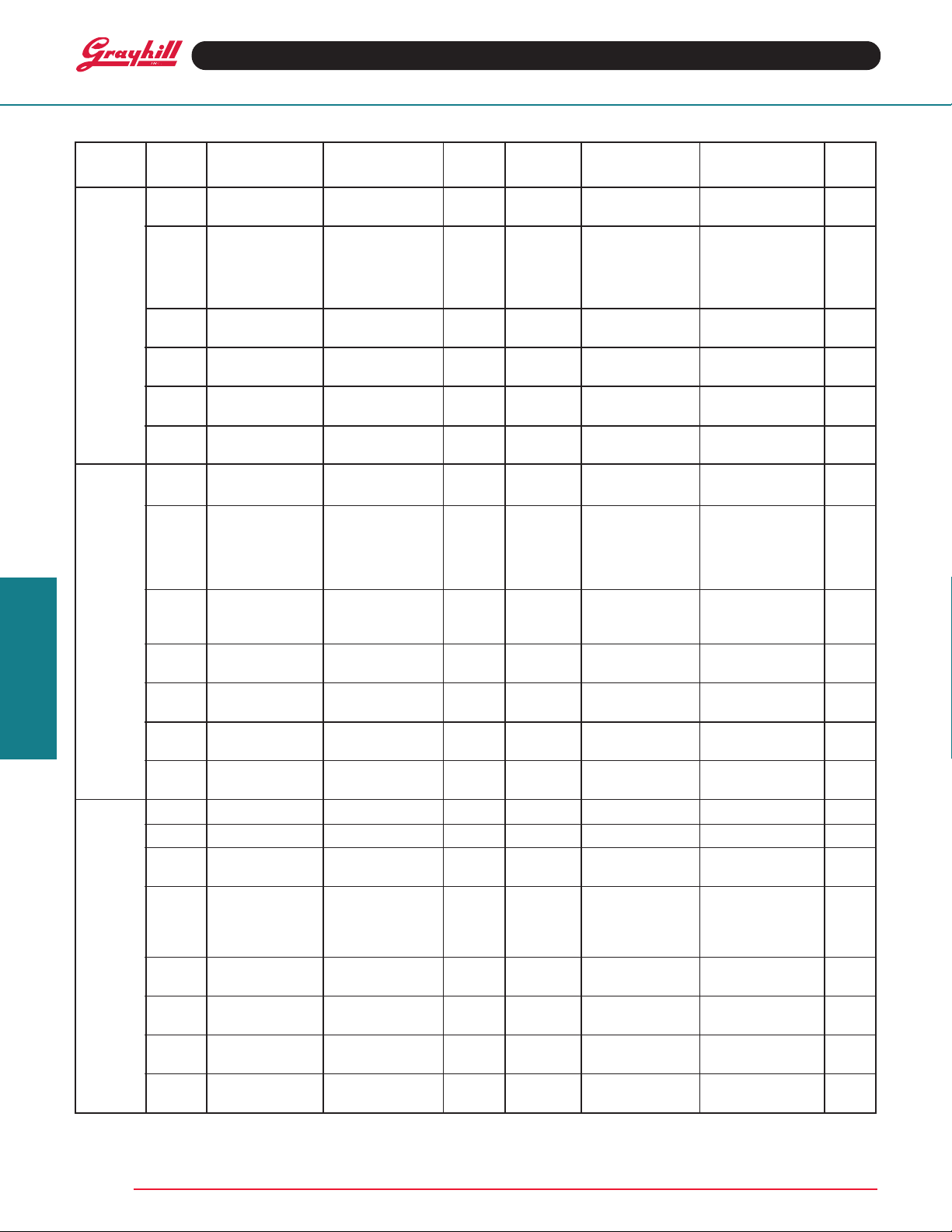
CHOICES AND LIMITATIONS
Con- Conven- Description Spring Return No. Poles Positions Per Location Of Term.
figur- tional Of Stem Number Of Per Pole & Contact Unique Position, Opp.
ation Switch Style (See Ordering Info.) Decks Deck Type Detent or Momentary Flat**
08A36 Standard 08317 1 to 6 1 02 to 05 (N or S) M 5 5
09A30 Standard 09310 1 or 2 3 02 to 04 (N or S) M 4, 8, 12 4
DDDD
DM
42A36 Standard 42349 1 to 3 1 02 to 05 (N or S) M 5 5
42M36 Military 42352 1 to 3 1 02 to 05 (N or S) M 5 5
44A30 Standard 44346 1 to 3 1 02 to 06 (N or S) M 6 6
44M30 Military 44350 1 to 3 1 02 to 06 (N or S) M 6 6
08A36 Standard 08319 1 to 6 1 02 to 05 (N or S) M 1 1
09A30 Standard 09312 1 or 2 3 02 to 04 (N or S) M 1, 5, 9 1
MD
DDDD 1 to 3 1 02 to 06 (N or S) M 1 1
Rotary Switches
MDM
*This is a complete (not stem) part number.
**Terminal opposite shaft flat when switch
is in its unique (detent or momentary)
position.
09M30 Military 09356 1 2 02 to 06 (N or S) M 1, 7 1
42A36 Standard 42350 1 to 3 1 02 to 05 (N or S) M 1 1
42M36 Military 42353 1 to 3 1 02 to 05 (N or S) M 1 1
44A30 Standard 44312 1 to 3 1 02 to 06 (N or S) M 1 1
44M30 Military 44351 1 to 3 1 02 to 06 (N or S) M 1 1
50A36 Std., Solder Lug 503265-1-03N* 1 1 03N D 2 2
50P36 Std., PC Mount 503267-1-03N* 1 1 03N D 2 2
8A36 Standard 08316 1 to 6 1 03 (N or S) D 2 2
9A30 Standard 09311 1 to 3 2 03 (N or S) D 2, 8 2
42A36 Standard 42348 1 to 3 1 03 (N or S) D 2 2
42M36 Military 42351 1 to 3 1 03 (N or S) D 2 2
44A30 Standard 44345 1 to 3 1 03 (N or S) D 2 2
44M30 Military 44349 1 to 3 1 03 (N or S) D 2 2
1 to 3 2 02 to 05 (N or S) M 5, 10 5
1 to 6 1 02 to 06 (N or S) M 6 6
1 to 3 2 02 to 06 (N or S) M 6, 12 6
1 4 02 or 03 (N or S) M 3, 6, 9, 12 3
1 5 or 6 02 (N or S) M 2, 4, 6, 8, 10, 12 2
1 2 02 to 05 (N or S) M 5, 10 5
1 2 02 to 05 (N or S) M 5, 10 5
1 2 02 to 06 (N or S) M 6, 12 6
1 2 02 to 06 (N or S) M 6, 12 6
1 to 3 2 02 to 05 (N or S) M 1, 6 1
1 to 6 1 02 to 06 (N or S) M 1 1
1 to 3 2 02 to 06 (N or S) M 1, 7 1
1 4 02 or 03 (N or S M 1, 4, 7, 10 1
1 5 or 6 02 (N or S) M 1, 3, 5, 7, 9, 11 1
1 3 02 to 04 (N or S) M 1, 5, 9 1
1 2 02 to 05 (N or S) M 1, 6 1
1 2 02 to 05 (N or S) M 1, 6 1
1 2 02 to 06 (N or S) M 1, 7 1
1 2 02 to 06 (N or S) M 1, 7 1
1 to 3 2 03 (N or S) D 2, 7 2
1 to 6 1 03 (N or S) D 2 2
1 or 2 3 03 (N or S) D 2, 6, 10 2
1 4 03 (N or S) D 2, 5, 8, 11 2
1 2 03 (N or S) D 2, 7 2
1 2 03 (N or S) D 2, 7 2
1 2 03 (N or S) D 2, 8 2
1 2 03 (N or S) D 2, 8 2
Available from your local Grayhill Distributor
For prices and discounts, contact a local Sales
Office, an authorized local Distributor, or Grayhill.
Grayhill, Inc. • 561 Hillgrove Avenue • LaGrange, Illinois 60525-5997 • USA • Phone: 708-354-1040 • Fax: 708-354-2820 • www.grayhill.com
Page 3

Special Function Rotary Switches
DIM.A
046 (1,17)
DIM. A + .046 –.020
(+ 0,05 –0,51)
SERIES 09, 42, 44, 50, 51
Isolated Position
FEATURES
• Protected Switch Positions For
Safety, Calibration, or Stand-by
• Choice of Push- or Pull-To-Turn
•1/2" Diameter, 200 mA and
1" Diameter, 1 Amp Switch
• 10,000 Cycles of Operation
DESCRIPTION
An isolated position is one which cannot be reached by the normal rotation. An additional action is
required by the operator. It could be either Push-To-Turn, or Pull-To-Turn. After the switch is rotated
to the isolated position, releasing the shaft locks the switch in that position. Push or pull again to
rotate the switch again.
Use isolated positions to protect a switch position from indiscriminate rotation. Such safety positions
might include “calibrate”, “off” and/or “stand-by”.
DIMENSIONS
Series 09 Series 42 & 44
+ .
–.020 (0,51)
.062 (1,57)
Series 50 & 51
DIM. A
SOLDER
LUGS
Rotary Switches
PC
TERMINALS
Materials and Finishes
Materials and finishes for the isolation
mechanism are listed here.
Housing: Zinc casting, tin/zinc-plated
Shaft: 303 stainless steel
Stop Pin and Stop Post: 303 stainless steel
Spring: Tinned music wire
Housing: Phenolic for style A; Diallyl, for M
Shaft: 303 stainless steel, electro-polished
Stop Pin and Stop Post: 303 stainless steel
Spring: Tinned music wire
Housing: Diallyl per MIL-M-14
Shaft: 303 stainless steel
Lock Plate: 302 stainless steel
Lock Arm: 316 stainless steel
Lock Post: Brass, tin/zinc-plated
Compression Spring: Tinned music wire
Dimension A
1 Deck 1.228 (31,19)
2 Decks 1.496 (38,0)
3 Decks 1.764 (44,81)
4 Decks 2.032 (51,61)
EXTERNAL DIFFERENCES
The isolated position mechanism increases the
depth of the Series 50 and 51 by 0.217" (5,51
mm). All other dimensions remain unchanged.
In Series 9, 42 and 44, it has the appearance of
an additional deck section without terminals,
located directly behind the detent system.
DIM. A
Dimension A
Solder Lug .893 ± .025 (22,68 ± 0,64)
PC Style .897 ± .025 (22,78 ± 0,64)
SPECIFICATIONS
Electrical Ratings
The switching elements, and therefore ratings,
are the same in an isolated position switch as in
a conventional rotary switch. Mechanical life is
also the same.
Additional Characteristics
Shaft Movement or Vertical Travel:
Series 09 .062 ± .020 (1,57 ± 0,51)
Series 42 & 44 .070 ± .020 (1,78 ± 0,51)
Series 50 & 51 .080 ± .020 (2,03 ± 0,51)
Push or Pull Force Required:
Series 09 1.75 ± .5 lbs
Series 42 & 44 2 ± .5 lbs
Series 50 & 51 2 ± .5 lbs
Stops: Single pole per deck switches with the
maximum number of positions are supplied with
stops only on request: 12 positions in 30° throw,
10 in 36°, and 8 in 45°.
Stop Strength: Approximately 7.5 pound-inches
for the isolated position stop.
Dimension A
1 Deck 1.371 (34,82)
2 Decks 1.717 (43,61)
3 Decks 2.063 (52,40)
4 Decks 2.409 (61,19)
Grayhill part number and date code marked on label.
Customer number marked on request.
Series 50 and 51
Series 09
Series 42 and 44
Grayhill, Inc. • 561 Hillgrove Avenue • LaGrange, Illinois 60525-5997 • USA • Phone: 708-354-1040 • Fax: 708-354-2820 • www.grayhill.com
Page 4

Special Function Rotary Switches
CHOICES AND LIMITATIONS
Standard Military Style Angle Of No. Of Poles Per Positions Shorting Or
Style Style** Description Throw Decks Deck Per Pole Non-Shorting
01 to 04 1 02 to 12 N or S
09A 09M Solder Lug 30° 01 to 04 3 02 to 04 N or S
42A 42M Solder Lug
42S — Sealed 36° 01 to 04 1 02 to 10 N or S
— 42H 125° Temperature Rating 01 to 04 2 02 to 05 N or S
— 42HS 125° Temp Rating, Sealed
30° 01 to 04 3 02 to 04 N or S
44A 44M Solder Lug 01 to 04 4 02 or 03 N or S
44S — Sealed 01 to 04 5 02 N or S
— 44H 125° Temperature Rating 01 to 04 6 02 N or S
— 44HS 125° Temp Rating, Sealed
45° 01 to 04 1 02 to 08 N or S
01 to 04 2 02 to 06 N or S
01 to 04 4 02 or 03 N or S
01 to 04 5 02 N or S
01 to 03 6 02 N or S
01 to 04 1 02 to 12 N or S
01 to 04 2 02 to 06 N or S
01 to 03 2 02 to 04 N or S
01 or 02 3 02 N or S
01 or 02 4 02 N
-- 50C Solder Lug
-- 50CP PC Mount 36° 01 1 02 to 10 N or S
-- 50M* Solder Lug, Sealed 2 02 to 05 N or S
-- 50MP* Sealed, PC
-- 51C Solder Lug 1 02 to 12 N or S
-- 51CP PC Mount 30° 01 2 02 to 06 N or S
-- 51M* Solder Lug, Sealed 3 02 or 03 N or S
-- 51MP* PC Mount, Sealed 4 02 or 03 N or S
*(Pull-to-Turn only) **For specifics on military qualified products, see Standard Switch Pages.
CONVENTIONAL NUMBERS
Start by creating a conventional switch number
in the manner which follows:
Series & Style
Angle of Throw
Number of Decks
09A30-01-1-12N
Type of Contacts
Shorting = S
Non-Shorting = N
Positions Per Pole
Poles Per Deck
Note: No stop arrangement suffix is needed.
See Describing Stops.
DESCRIBING POSITIONS
The Grayhill system for isolating positions lets
you choose the positions to be isolated. Grayhill
inserts isolation posts next to the positions to be
isolated. Consider a continuous rotation switch
of the Series 09A with a 30° angle of throw. The
terminals are listed here from 1 through 12 with
a space between each to indicate where isolation
posts might be inserted.
12123456789101112
Let's isolate position 1 and position 2 from all
other positions and from each other. We indicate
isolation posts as shown here:
12P1P2P3 4 5 6 7 8 9 10 11 12
To isolate just position 1, describe like this:
12P1P2 3 4 5 6 7 8 9 10 11 12
To isolate positions 1 and 2 from all other
positions, but not from each other, do this:
12P1 2P3 4 5 6 7 8 9 10 11 12
DESCRIBING STOPS
When a 1-pole switch has less than the maximum
number of positions, consider also the stop
system. Following is the arrangement for a 6
position switch with the position 1 isolated.
STOP 1P2 3 4 5 6 STOP
The word “STOP” indicates the conventional
switch stops, which limit rotation to positions 1
through 6. To isolate position 1 we insert only
one isolation post–between terminals 1 and 2.
The stop system already prevents rotation
beyond terminal 1.
In multi-pole switches, the stop system and
isolation system described for the first pole,
automatically affects the other poles. In the
example above, isolating position #1 on the first
pole isolates the first position (terminal #7) of
the second pole. See Standard Switch Pages
for a 2 pole circuit diagram for a 30° throw
switch.
ORDERING INFORMATION
Indicate this as a SPECIAL switch to ensure
that no error is made when the order is entered.
Sample part number:
SPECIAL
09A30-04-1-12N
PULL 12P1P2P3 4 5 6 7 8 9 10 11 12
This sample part number orders a Series 9
standard style, four deck, one pole per deck,
twelve positions per pole rotary switch with nonshorting contacts and isolation posts between
positions 12 and 1, between 1 and 2, and
between 2 and 3.
This lengthy order number is required to prevent
any possible confusion in ordering the switch.
When we receive your order, we will assign a
special “short form” part number to facilitate
future identification of this special switch. This
number is sequentially assigned as the need
arises, and is non-descriptive. A typical “short
form” special part number might be 09YY12345.
Contact Grayhill for price.
Not available through Distributors.
Rotary Switches
Grayhill, Inc. • 561 Hillgrove Avenue • LaGrange, Illinois 60525-5997 • USA • Phone: 708-354-1040 • Fax: 708-354-2820 • www.grayhill.com
 Loading...