

Grayhill Single Deck Rotary Switches 75 User Manual
Single Deck Rotary Switches
.298 ± .010
(7,57 ± 0,25)
DIA.
SCREWDRIVER SLOT
.032 ± .010
(0,81 ± 0,25) DEEP
.125 ± .005
(3,18 ± 0,13)
.020 ± .005
(0,51 ± 0,13)
0
1
2
3
4
5
6
7
8
9
.489 ± .020
(12,42 ± 0,51)
.109 ± .010
(2,77 ± 0,25)
.032 (0,81)
REF.
SHOULDER
DIAMETER
Ø .031 ± .002
(0,79 ± 0,05)
TERMINAL
DIAMETER
Ø .015 ± .002
(0,38 ± 0,05)
2 1 10 9
2 1 10 9
.539 ± .020
(13,69 ± 0,51)
.109 ± .010
(2,77 ± 0,25)
2 1 10 9
.550 ± .020
(13,97 ± 0,51)
.109 ± .010
(2,77 ± 0,25)
.298 ± .010
(7,57 ± 0,25)
DIA.
.203 ± .003
(5,16 ± 0,08)
ACROSS FLATS
OF BUSHING
.094 ± .015
(2,39 ± 0,38)
108°
C
L
OF
POSITION 1
2 1 10 9
.500 ± .020
(12,7 ± 0,51)
.250
± .015
(6,35
± 0,38)
.109 ± .010
(2,77 ± 0,25)
.032 (0,81)
REF.
1/4-32 UNF-2A
THREAD
.375 ± .015
(9,53 ± 0,38)
.250
± .015
(6,35
± 0,38)
Ø .125 + .001/ - .002
(3,18 + 0,03/ - 0,51)
SHOULDER
DIAMETER
Ø .031 ± .002
(0,76 ± 0,05)
TERMINAL
DIAMETER
Ø .015 ± .002
(0,38 ± 0,05)
.489 ± .020
(12,42 ± 0,51)
.109 ± .010
(2,77 ± 0,25)
.032 (0,81)
REF.
2 1 10 9
.115 ± .010
(2,92 ± 0,25)
.539 ± .020
(13,69 ± 0,51)
2 1 10 9
.109 ± .010
(2,77 ± 0,25)
.298 ± .010
(7,57 ± 0,25)
DIA.
C
L
OF
POSITION 1
SHOULDER
DIAMETER
Ø .031 ± .002
(0,76 ± 0,05)
TERMINAL
DIAMETER
Ø .015 ± .002
(0,38 ± 0,05)
SERIES 75
0.3" Diameter, 200 mA
FEATURES
•SmallSize
•Flush,Shafted,orKnobbedShaft
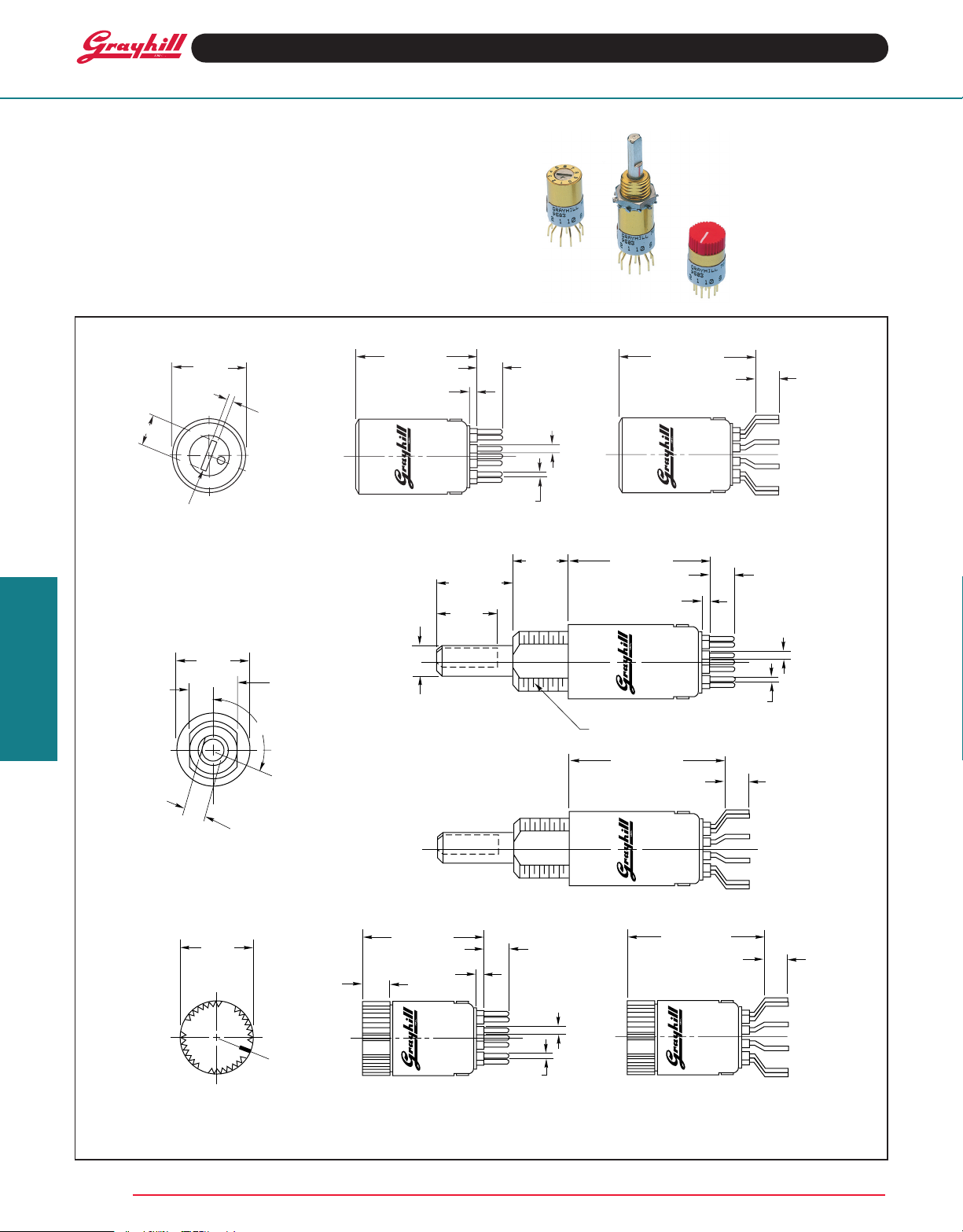
DIMENSIONS in inches (and millimeters)
Screwdriver Actuated
Rear view shown
on next page.
Rotary Switches
Shaft Actuated
Integral Knob Actuated
Grayhill, Inc. • 561 Hillgrove Avenue • LaGrange, Illinois 60525-5997 • USA • Phone: 708-354-1040 • Fax: 708-354-2820 • www.grayhill.com
Style AP Style AF
All dimensions not shown and
front views same as style BP.
Style CP Style CF
Grayhill part number and date code marked on label.
Customer part number marked on request.
All dimensions not shown and
front views same as style AP.
Style BP
Style BF
All dimensions not shown and
front views same as style CP.
Rear view shown
on next page.
Rear view shown
on next page.
Rear view shown
on next page.

CIRCUIT DIAGRAMS AND REAR VIEWS
.298 ± .010
(7,57 ± 0,25)
COMMON LOCATION
FOR A TWO POLE
SWITCH LOCATED ON
.064 ± .010 (1,63 ± 0,25)
DIA. CIRCLE OF CENTERS
36° ± 3°
TYP.
COMMON LOCATION
FOR A SINGLE POLE
SWITCH
36° ± 3°
TYP.
1
2
3
4
5
6
7
8
9
10
1
2
3
4
5
6
7
8
9
10
1
2
3
4
5
6
7
8
9
10
1
2
3
4
5
6
7
8
9
10
1
2
3
4
5
6
7
8
9
10
1
2
3
4
5
6
7
8
9
10
300
200
100
0
0510 15
CYCLES x 1,000
CURRENT
(MILLIAMPS)
CURVE B: 115 Vac or 30 Vdc
CURVE A: 220 Vac
A
B
Style P
Circle of terminal centers is
Ø .187 ± .010 (4,75 ± 0,25).
Screwdriver Actuated Integral Knob Actuated Shaft Actuated
Dot on actuator is next to contacting position of pole 1.
36° ANGLE
OF THROW
Switch is viewed
from actuator
end and shown in
Position 1.
ONE POLE TWO POLE
Single Deck Rotary Switches
Line on knob points to contacting position of pole 1.
ONE POLE TWO POLE
Style F
Circle of terminal centers is
Ø .300 ± .010 (7,62 ± 0,25).
Shaft flat opposite point of contact of pole 1.
ONE POLE TWO POLE
SPECIFICATIONS
Electrical Ratings
Chart shown for non-shorting (break before
make) contacts, resistive load.
minimum between mutually insulated parts.
Voltage Breakdown: 500 Vac between mutually
insulated parts.
Life Expectancy: 10,000 cycles at 200 milliamps.
One cycle is 360° rotation and a return through
all switch positions to the starting position.
Low Level Rating: Make and break a 50 mV, 1
milliamp, resistive load for 10,000 cycles with a
maximum contact resistance of 50 milliohms.
Bushing:Brass,tinzincplating
Stop Pin: Stainless steel, passivated
Detent Balls: Steel, nickel-plated
Detent and Contact Springs: Tinned music
wire
Rotor Contact: Silver cad-oxide, gold-plated
Terminals and Common: Brass, gold plate
.00002" minimum thickness over silver plate
.0003" minimum.
Shaft in Style BF or BP: Zinc
One cycle is 360° rotation and a return through
all switch positions to the starting position. The
data for the curve was measured at sea level,
25°C and 68% relative humidity with the following
limiting criteria:
Contact Resistance: 50 milliohms maximum
(15 milliohms initially).
Insulation Resistance: 10 ,000 Mo hms
Contact Grayhill for information if the life limiting
criteria is more critical than those listed, if the
required cycles of operation are greater than
those listed, if a larger make and break current
is required than the one listed for the desired
number of cycles, or if elevated temperatures
or reduced pressures are part of the operating
environment.
Materials and Finishes
Switch Base: Diallyl per MIL-M-14
Detent Cover and Detent Rotor in Styles AP,
AF, BP, and BF: Phenolic per MIL-M-14
Integral Knob and Detent Rotor in Style CF
or CP: Red Thermoplastic
Mounting Hardware for Style BF or BP: One
mounting nut .062" thick by .312" across flats
and one external tooth lockwasher supplied with
eachswitch.Mountingnutisbrass,zincplated
and lockwasher is spring steel.
Additional Characteristics
Contact Type: Non-shorting, wiping contacts
Terminals: Switches are provided with the full
circle of terminals regardless of the number of
active positions.
Stop Strength: 8 ounce-inches minimum
CHOICES AND LIMITATIONS
Style and Designation Number of Decks
Ø 0.187 (4,75) Ø 0.300 (7,62) Angle Poles Non- Number of
Circle of Term. Circle of Term. Of Throw Per Deck Shorting Positions/Pole
AP = Screwdriver AF = Screwdriver
Actuated Actuated 36° Fixed Printed 1 Not 1 2 thru 10
BP = Shaft Operated BF = Shaft Operated 2 Available 1 2 thru 5
CP=IntegralKnob CF=IntegralKnob
Stops Terminal Shorting
Rotary Switches
ORDERING INFORMATION
Grayhill, Inc. • 561 Hillgrove Avenue • LaGrange, Illinois 60525-5997 • USA • Phone: 708-354-1040 • Fax: 708-354-2820 • www.grayhill.com
Series
Style: Letters from Choices and Limitations Chart
Angle of Throw: 36° only
75AP36–01–1–10N–C
Stop Arrangement: The suffix C or F must be added to a
one pole per deck switch to indicate continuous rotation (C) or fixed
stop (F) between position 1 and position 10.
Type of Contacts: N=Non-shorting only
Positions per Pole: requires 02 positions as a minimum to
maximum allowable dependent on the poles per deck
Poles per Deck: 1 or 2 poles available
Number of Decks: 1 deck only
Available from your local
Grayhill Distributor.
For prices and discounts, contact a local
SalesOfce,anauthorizedlocalDistributor,
or Grayhill.
 Loading...